EP4244079B1 - Fahrzeugluftreifen - Google Patents
Fahrzeugluftreifen Download PDFInfo
- Publication number
- EP4244079B1 EP4244079B1 EP21806983.9A EP21806983A EP4244079B1 EP 4244079 B1 EP4244079 B1 EP 4244079B1 EP 21806983 A EP21806983 A EP 21806983A EP 4244079 B1 EP4244079 B1 EP 4244079B1
- Authority
- EP
- European Patent Office
- Prior art keywords
- channel
- groove
- transverse
- blind
- pneumatic vehicle
- Prior art date
- Legal status (The legal status is an assumption and is not a legal conclusion. Google has not performed a legal analysis and makes no representation as to the accuracy of the status listed.)
- Active
Links
Images


Classifications
-
- B—PERFORMING OPERATIONS; TRANSPORTING
- B60—VEHICLES IN GENERAL
- B60C—VEHICLE TYRES; TYRE INFLATION; TYRE CHANGING; CONNECTING VALVES TO INFLATABLE ELASTIC BODIES IN GENERAL; DEVICES OR ARRANGEMENTS RELATED TO TYRES
- B60C11/00—Tyre tread bands; Tread patterns; Anti-skid inserts
- B60C11/03—Tread patterns
- B60C11/0306—Patterns comprising block rows or discontinuous ribs
- B60C11/0309—Patterns comprising block rows or discontinuous ribs further characterised by the groove cross-section
-
- B—PERFORMING OPERATIONS; TRANSPORTING
- B60—VEHICLES IN GENERAL
- B60C—VEHICLE TYRES; TYRE INFLATION; TYRE CHANGING; CONNECTING VALVES TO INFLATABLE ELASTIC BODIES IN GENERAL; DEVICES OR ARRANGEMENTS RELATED TO TYRES
- B60C11/00—Tyre tread bands; Tread patterns; Anti-skid inserts
- B60C11/03—Tread patterns
- B60C11/0306—Patterns comprising block rows or discontinuous ribs
-
- B—PERFORMING OPERATIONS; TRANSPORTING
- B60—VEHICLES IN GENERAL
- B60C—VEHICLE TYRES; TYRE INFLATION; TYRE CHANGING; CONNECTING VALVES TO INFLATABLE ELASTIC BODIES IN GENERAL; DEVICES OR ARRANGEMENTS RELATED TO TYRES
- B60C11/00—Tyre tread bands; Tread patterns; Anti-skid inserts
- B60C11/03—Tread patterns
- B60C2011/0337—Tread patterns characterised by particular design features of the pattern
- B60C2011/0339—Grooves
- B60C2011/0358—Lateral grooves, i.e. having an angle of 45 to 90 degees to the equatorial plane
- B60C2011/0365—Lateral grooves, i.e. having an angle of 45 to 90 degees to the equatorial plane characterised by width
-
- B—PERFORMING OPERATIONS; TRANSPORTING
- B60—VEHICLES IN GENERAL
- B60C—VEHICLE TYRES; TYRE INFLATION; TYRE CHANGING; CONNECTING VALVES TO INFLATABLE ELASTIC BODIES IN GENERAL; DEVICES OR ARRANGEMENTS RELATED TO TYRES
- B60C11/00—Tyre tread bands; Tread patterns; Anti-skid inserts
- B60C11/03—Tread patterns
- B60C2011/0337—Tread patterns characterised by particular design features of the pattern
- B60C2011/0339—Grooves
- B60C2011/0358—Lateral grooves, i.e. having an angle of 45 to 90 degees to the equatorial plane
- B60C2011/0367—Lateral grooves, i.e. having an angle of 45 to 90 degees to the equatorial plane characterised by depth
- B60C2011/0369—Lateral grooves, i.e. having an angle of 45 to 90 degees to the equatorial plane characterised by depth with varying depth of the groove
-
- B—PERFORMING OPERATIONS; TRANSPORTING
- B60—VEHICLES IN GENERAL
- B60C—VEHICLE TYRES; TYRE INFLATION; TYRE CHANGING; CONNECTING VALVES TO INFLATABLE ELASTIC BODIES IN GENERAL; DEVICES OR ARRANGEMENTS RELATED TO TYRES
- B60C11/00—Tyre tread bands; Tread patterns; Anti-skid inserts
- B60C11/03—Tread patterns
- B60C2011/0337—Tread patterns characterised by particular design features of the pattern
- B60C2011/0339—Grooves
- B60C2011/0358—Lateral grooves, i.e. having an angle of 45 to 90 degees to the equatorial plane
- B60C2011/0372—Lateral grooves, i.e. having an angle of 45 to 90 degees to the equatorial plane with particular inclination angles
-
- B—PERFORMING OPERATIONS; TRANSPORTING
- B60—VEHICLES IN GENERAL
- B60C—VEHICLE TYRES; TYRE INFLATION; TYRE CHANGING; CONNECTING VALVES TO INFLATABLE ELASTIC BODIES IN GENERAL; DEVICES OR ARRANGEMENTS RELATED TO TYRES
- B60C11/00—Tyre tread bands; Tread patterns; Anti-skid inserts
- B60C11/03—Tread patterns
- B60C2011/0337—Tread patterns characterised by particular design features of the pattern
- B60C2011/0339—Grooves
- B60C2011/0381—Blind or isolated grooves
-
- B—PERFORMING OPERATIONS; TRANSPORTING
- B60—VEHICLES IN GENERAL
- B60C—VEHICLE TYRES; TYRE INFLATION; TYRE CHANGING; CONNECTING VALVES TO INFLATABLE ELASTIC BODIES IN GENERAL; DEVICES OR ARRANGEMENTS RELATED TO TYRES
- B60C11/00—Tyre tread bands; Tread patterns; Anti-skid inserts
- B60C11/03—Tread patterns
- B60C2011/0337—Tread patterns characterised by particular design features of the pattern
- B60C2011/0386—Continuous ribs
- B60C2011/0388—Continuous ribs provided at the equatorial plane
Definitions
- the invention relates to a pneumatic vehicle tire with a tread having at least one row of profile blocks delimited on each side by a circumferential groove, which is divided into profile blocks by a plurality of transverse grooves which open into both circumferential grooves and run parallel to one another in plan view, wherein each transverse groove, viewed in plan view, is composed of two groove sections which adjoin one another at an obtuse angle of 100° to 160°, wherein in each profile block there is formed a blind groove which opens into both groove sections of a transverse groove and is elongated in plan view, which forms a groove combination with the transverse groove which runs in a Y-like manner in plan view and runs at an angle of 0° to 60° to the circumferential direction.
- Such a pneumatic vehicle tire is known, for example, from US 2004/0134580 A1 known.
- the pneumatic vehicle tire has a tread with a central row of tread blocks located in the central tread area, bordered on each side by a circumferential groove, which is structured into tread blocks by transverse grooves that open into the circumferential grooves.
- each tread block there is a elongated, funnel-shaped blind groove that opens into both groove sections of a transverse groove, runs at an angle of 0° to the circumferential direction and has a minimum width of 7.0 mm to 15.0 mm in the axial direction.
- the tire should have good snow performance.
- the EP 2 748 017 B1 discloses a pneumatic vehicle tire with a tread having a central tread block row forming the central tread area and two shoulder-side tread block rows.
- the central tread block row is separated on each side by a circumferential groove, takes up at least 30% of the width of the ground contact area of the tread and is provided with V-shaped first transverse grooves which open into the circumferential grooves and are each composed of two groove sections.
- the middle row of tread blocks is provided with second transverse grooves, which each run in the area between two circumferentially successive, parallel groove sections of the first transverse grooves and open into a groove section of a first transverse groove which is inclined in the opposite direction to the circumferential direction.
- the groove sections each run at an angle of 60° to 85° to the circumferential direction, so that the groove sections enclose an angle of, for example, 120°.
- blind grooves which run in the circumferential direction in plan view are formed, each opening into a groove section of a transverse groove.
- the tire should have good driving characteristics on snow and ice.
- the DE 43 00 695 A1 discloses a pneumatic vehicle tire with a tread having a central tread block row forming the central tread region and two shoulder-side tread block rows.
- the central tread block row is bordered on each side by a circumferential groove that runs zigzag in plan view and is provided with V-shaped transverse grooves that open into the circumferential grooves, each of which is composed of two groove sections that adjoin one another in the region of the tire's equatorial plane.
- the groove sections enclose an angle of preferably 100°.
- blind grooves are also provided, each of which runs as an extension of one groove section of a transverse groove.
- the tire is said to have good aquaplaning behavior and good winter performance.
- the US 2019/0283506 A1 discloses a pneumatic vehicle tire with a tread having five rows of tread blocks.
- the semi-central rows of tread blocks have tread blocks separated from one another by transverse grooves, which, in plan view, consist of two groove sections extending in a V-shape relative to one another.
- a blind groove is formed, which extends as an extension of one groove section of the respective transverse groove.
- a pneumatic vehicle tire with a tread which has a central row of tread blocks in each tread half, which is divided into tread blocks by transverse grooves which are V-shaped in plan view and grooves which open into these.
- the EP 3 300 926 A1 A tire with a tread which is divided into two shoulder-side tread block rows and two middle tread block rows by a central circumferential groove and two shoulder-side circumferential grooves.
- the middle tread block rows are divided into tread blocks by transverse grooves opening into the circumferential grooves, with the transverse grooves each consisting of two groove sections adjoining one another at an obtuse angle of 130° to 150°, with the groove section opening into the shoulder-side circumferential groove being shorter than the groove section opening into the central circumferential groove.
- an additional groove is formed between adjacent transverse grooves in the circumferential direction, which is straight in plan view and runs at an angle of 5° to 15° to the circumferential direction.
- This additional groove divides the respective tread block into essentially equal-sized block parts and widens in a funnel shape towards the shoulder-side circumferential groove. At the wider ends of the additional grooves, a base elevation is also formed in the transverse grooves.
- the tire exhibits a high balance of the desired properties for good all-season suitability, particularly with regard to tread stiffness, which is responsible for handling characteristics, water drainage capacity, which ensures aquaplaning resistance, and driving characteristics on snow.
- the tread pattern with transverse grooves merging into circumferential grooves is, on the one hand, particularly beneficial with regard to tread drainage (shorter water displacement paths) and, on the other hand, due to the provided transverse groove edges, for wet and snow grip properties. Intersecting grooves also contribute to tread drainage and improve wet and snow grip properties. However, with existing tread patterns, these properties are not optimally matched to the tire's dry performance. In particular, there is a risk that tread modifications intended to improve snow grip properties could be accompanied by a deterioration in dry performance and/or drainage properties.
- the invention is therefore based on the object of improving the snow grip properties when cornering forces occur in a pneumatic vehicle tire of the type mentioned at the outset, while maintaining good dry performance and good drainage properties.
- the blind groove has a width of 1.0 mm to 6.0 mm determined on the tread periphery and is curved in plan view such that the angle at which it runs to the circumferential direction increases by 15° to 40°, in particular by 20° to 30°, from its groove end located on the transverse groove to its groove end located in the interior of the tread block.
- the blind grooves do not traverse the tread blocks, the high rigidity of the tread rib is maintained, which is beneficial for dry performance.
- the Y-shaped groove combination effectively drains water absorbed by the blind grooves via the groove sections of the transverse grooves in both "axial directions"—i.e., both circumferential grooves bordering the central tread rib—thus maintaining good drainage properties.
- the curved shape of the blind groove contributes particularly to effective snow compaction in the blind groove when driving on snow, further improving snow grip when cornering forces occur.
- the angle at which the blind groove extends to the circumferential direction is 10° to 60°, in particular 20° to 50°.
- Such an inclination of the blind groove is favorable for the effect of the groove edges of the blind groove under loads that have a force component acting in the circumferential direction, so that this measure contributes to an improvement in snow grip properties.
- an inclined blind groove under loads acting in the circumferential direction, especially during braking, increased support effects occur compared to a blind groove running exactly in the circumferential direction, which are favorable for block stiffness and therefore for dry performance.
- the profile block row runs in one of the tread halves, wherein the blind groove runs from the transverse groove in the direction of that of the two circumferential grooves which is the shoulder-side circumferential groove.
- the blind groove has a distance of at least 3.0 mm and preferably no more than 15.0 mm, measured in the circumferential direction at the tread periphery, from its groove end located inside the tread block—relative to its groove centerline—to the transverse groove adjacent to the tread block, from which the blind groove does not originate. This measure contributes to maintaining a high level of rigidity, which is beneficial for dry performance.
- the blind groove has a distance of at least 3.0 mm and preferably of at most 15.0 mm from its groove end located inside the profile block - based on its groove center line - to the nearest circumferential groove, determined in the axial direction on the tread periphery.
- the width of the blind groove decreases continuously from the transverse groove over the entire extent of the blind groove, wherein the width of the blind groove at its groove end located inside the profile block is 30% to 80%, in particular 50% to 70%, of the width of the blind groove at the transverse groove.
- Blind grooves with such a decreasing width contribute to maintaining a high This increases the stiffness of the tread blocks and thus contributes to maintaining dry performance.
- such a blind groove allows snow to compact particularly well when driving on snowy roads, which is beneficial for snow grip.
- the blind groove has a depth in the radial direction that decreases from the transverse groove toward its groove end located inside the tread block. This contributes to faster compaction of snow in the blind groove when driving on a snowy road surface. Furthermore, this measure is advantageous with regard to rigidity and dry performance.
- the depth of the blind groove on the transverse groove matches the depth of the transverse groove. This allows water absorbed by the blind groove to flow into the transverse groove with minimal turbulence.
- the depth of the blind groove at its groove end located inside the profile block is 2.0 mm to 3.0 mm.
- the blind groove is delimited in the radial direction by a groove base which, viewed in a longitudinal section aligned along the groove centerline of the blind groove, is composed of a first base section adjoining the groove base of the transverse groove and running at the depth of the transverse groove, a middle, second base section, and a third base section, wherein the second base section runs at an angle of 40° to 50° to the radial direction and the third base section runs at an angle of 65° to 75° to the radial direction, and wherein the third base section adjoins the second base section at a depth, determined in the radial direction, of 50% to 85%, in particular 65% to 75%, of the depth of the transverse groove.
- the base sections contribute to stabilizing the tread block in the area of the blind groove and are therefore beneficial for the rigidity of the tread block and thus for dry performance. Furthermore, the base sections promote snow compaction in the sack groove and thus contribute to a further improvement of the snow grip properties when lateral forces occur.
- a further preferred embodiment is characterized in that the groove sections of the transverse groove, viewed in plan view and relative to the groove centerline, each extend at an angle of 10° to 40°, in particular 20° to 35°, to the axial direction. This is particularly advantageous for the drainage properties.
- the groove sections of the transverse groove are curved in plan view such that their angle to the axial direction—starting from a kink point present at the mutual connection of the groove sections on the groove centerline—increases by 5° to 25°, in particular by 10° to 20°, toward the circumferential grooves. This promotes rapid water drainage into the circumferential grooves.
- a further preferred embodiment is characterized in that the angles of the groove sections to the axial direction - determined at a kink point present at the mutual connection of the groove sections on the groove center line - are the same or differ from each other by at most 10°.
- the obtuse angle at which the groove sections of the transverse groove adjoin one another is 110° to 140°, preferably 115° to 135°.
- the groove sections of the transverse groove have a kink point on the groove centerline at their mutual connection, which is located within a distance, measured in the axial direction from the tread block row centerline, of up to 10%, preferably up to 5%, of the width of the central tread block row measured in the axial direction at the tread periphery. This contributes to uniform drainage of the tread block.
- Pneumatic vehicle tires designed according to the invention are tires for motor vehicles, in particular for multi-track motor vehicles, and preferably tires of radial design for passenger cars, vans or light trucks, the tires being intended for use under winter driving conditions.
- Fig. 1 shows a plan view of a circumferential section of a tread of a pneumatic vehicle tire.
- the tire equatorial plane is indicated by a dashed line AA.
- the tread has a tread width TW45 in the axial direction, which is determined between two lines l running in the circumferential direction.
- Each line l appears, viewed in the cross-section of the tire, as a point on the outer contour line (the envelope) of the tire, at which point a tangent to the outer contour line forms an angle of 45° with the radial direction (vertical line).
- the width TW45 is determined with the pneumatic vehicle tire mounted on a standard rim according to ETRTO standards, at a tire pressure of 0.1 bar and without load.
- the tread has two shoulder-side tread block rows 1, a central tread rib 2 running in the area of the tire equatorial plane (line AA), and two central tread block rows 3 running in the different tread halves.
- the shoulder-side tread block rows 1 are separated from the central tread block rows 3 by shoulder-side circumferential grooves 4, which are straight in plan view.
- the circumferential grooves 4, 5 are designed in the radial direction to the respectively intended tread depth, which for the preferred tire type is usually 6.5 mm to 10.0 mm.
- the shoulder-side profile block rows 1 and the central profile rib 2 are shown in a simplified manner and can be designed in a manner known per se.
- Each central tread block row 3 has a maximum width b PR of 15% to 23%, in particular 17% to 21%, of the tread width TW45 on the tread periphery in the axial direction, as well as a tread block row centerline m PR running in the circumferential direction in plan view and bisecting the central tread block row 3 in relation to its width b PR .
- each central tread block row 3 is provided with a plurality of transverse grooves 6 which, when viewed from above, are parallel to one another and each have a shallow V-shape, opening into the corresponding shoulder-side circumferential groove 4 and the corresponding central circumferential groove 5, which structure the respective tread block row 3 into tread blocks 3a. From each transverse groove 6, in the region of its V-tip, a blind groove 7 extends into the respective tread block 3a and ends therein, which blind groove 7 forms a Y-shaped groove combination with the transverse groove 6 in plan view.
- the Y-shaped groove combinations of the middle tread block row 3 located in one tread half are rotated by 180° in plan view relative to the Y-shaped groove combinations of the middle tread block row 3 located in the other tread half.
- the further design of the transverse grooves 6 and the blind grooves 7 is explained below using a single Y-shaped groove combination.
- Fig. 2 shows an enlarged top view of a Y-shaped groove combination from the Fig. 1 right middle tread block row 3.
- the groove center line m QR following the groove course and extending to the circumferential grooves 4, 5 is shown in dashed lines, which - corresponding to the V-shaped course of the transverse groove 6 - has a kink point k l in the area of the V-tip of the transverse groove 6, which in the illustrated embodiment lies on the tread block row center line m PR .
- the kink point k l can be located within a distance from the tread block row center line m PR in the axial direction of up to 10%, preferably up to 5%, of the width b PR of the tread block row 3, so that the kink point k l is aligned with the tread block row center line m PR both in the axial direction direction (towards the shoulder-side circumferential groove 4) as well as the other axial direction (towards the central circumferential groove 5).
- the transverse groove 6, viewed in plan view, is composed of a groove section 6a opening into the shoulder-side circumferential groove 4 and a groove section 6b opening into the central circumferential groove 5, wherein the groove sections 6a, 6b adjoin one another at the kink point k l with respect to the groove center line m QR and are inclined in opposite directions to one another in accordance with the V-shaped course of the transverse groove 6 with respect to the axial direction.
- the groove section 6a runs slightly curved in plan view and, with respect to the axial direction with respect to the groove center line m QR , at an angle ⁇ of 10° to 40°, in particular of 20° to 35°, wherein the angle ⁇ increases by 5° to 25°, in particular by 10° to 20°, starting from the kink point k l in the direction of the shoulder-side circumferential groove 4.
- the groove section 6b also runs slightly curved in plan view and, relative to the groove center line m QR , at an angle ⁇ of 10° to 40°, in particular 20° to 35°, to the axial direction, with respect to the groove center line m QR , wherein the angle ⁇ increases by 5° to 25°, in particular 10° to 20°, starting from the bending point k l in the direction of the central circumferential groove 5.
- the angles ⁇ and ⁇ coincide at the bending point k l or differ from each other by a maximum of 10°.
- the sizes of the angles ⁇ and ⁇ are selected such that the groove section 6a and the groove section 6b - relative to the groove center line m QR - enclose an angle ⁇ which adds up the angles ⁇ and ⁇ to 180° and is 100° to 160°, in particular 110° to 140°, and preferably 115° to 135°.
- the transverse groove 6 is delimited by a groove base 6c, a groove flank 6d on the inside of the bend and a groove flank 6e on the outside of the bend, whereby the groove flank 6d on the inside of the bend is closer to a line l 1 running straight between the ends of the groove center line m QR in plan view than the groove flank 6e on the outside of the bend.
- the transverse groove 6 has a preferably constant depth t QR ( Fig. 3 ) of 75% to 100%, in particular of 85% to 95%, of the tread depth and an at least substantially constant width b QR of 2.0 mm to 6.0 mm, in particular of a maximum of 5.0 mm, determined perpendicular to the groove centre line m QR .
- the blind groove 7 adjoins both groove sections 6a, 6b of the transverse groove 6 and extends - with respect to the kink point k 1 of the center line m QR of the transverse groove 6 - in the opposite circumferential direction to the groove sections 6a, 6b.
- the blind groove 7 therefore adjoins the groove sections 6a, 6b via the groove flank 6e on the outside of the kink.
- the blind groove 7, viewed in plan view, is elongated along its groove center line m R following the groove course, whereby the groove center line m R continued into the transverse groove 6 coincides with the kink point k l of the center line m QR of the transverse groove 6 in the embodiment shown.
- the groove center line m R continuing into the transverse groove 6 can meet the center line m QR of the transverse groove 6 at a distance of up to 2.0 mm, in particular up to 1.0 mm, determined in the axial direction from the bending point k l.
- the blind groove 7 runs slightly curved in plan view and - based on the groove center line m R - to the circumferential direction at an angle ⁇ of 10° to 60°, in particular of 20° to 50°, wherein the angle ⁇ increases by 15° to 40°, in particular by 20° to 30°, starting from the groove end of the blind groove 7 located on the transverse groove 6 to the groove end of the blind groove 7 located inside the profile block 3a, and wherein the blind groove 7 runs from the transverse groove 6 in the direction of the shoulder-side circumferential groove 4.
- the blind groove 7 has a distance a 1 determined in the circumferential direction on the tread periphery from its end located inside the tread block 3a - in each case relative to the groove center line m R - to the transverse groove 6 delimiting the tread block 3a, from which the blind groove 7 does not originate, and a distance a 2 determined in the axial direction on the tread periphery from the shoulder-side circumferential groove 4, wherein the distances a 1 , a 2 are each at least 3.0 mm and preferably a maximum of 15.0 mm.
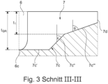
- the blind groove 7 is formed by a groove flank 7a adjoining the groove section 6a of the transverse groove 6, a groove flank 7b adjoining the groove section 6b of the transverse groove 6, a groove base 7c (cf. Fig. 3 ) and an end flank 7d running between the groove flanks 7a, 7b.
- the groove flanks 7a, 7b and the end flank 7d run, viewed in cross-section, in the radial direction or at an angle to it of up to 5°.
- the Groove base 7c viewed in the longitudinal section aligned along the groove center line m R , consists of a base section 7c' adjoining the groove base 6c of the transverse groove 6 and extending at a depth t QR , a middle base section 7c" and a base section 7c′′′.
- the middle base section 7c" extends, viewed in the aforementioned longitudinal section, to the radial direction at an angle ⁇ of 40° to 50°.
- the base section 7c′′′ adjoins the central base section 7c" at a depth t 1 determined in the radial direction of 50% to 85%, in particular of 65% to 75%, of the depth t QR and runs, viewed in the aforementioned longitudinal section, at an angle ⁇ of 65° to 75° to the radial direction.
- the blind groove 7 has a depth in the radial direction which decreases from the transverse groove 6 towards the end of the blind groove 7 located inside the profile block 3a to in particular 2.0 mm to 3.0 mm. According to Fig.
- the blind groove 7 has a width b R of 1.0 mm to 6.0 mm, in particular 2.0 mm to 4.5 mm, determined perpendicular to the groove center line m R on the tread periphery, wherein the width b R in the illustrated embodiment decreases continuously from the transverse groove 6 over the extent of the blind groove 7.
- the width b R of the blind groove 7 at its end flank 7d is 30% to 80%, in particular 50% to 70%, of the width b R of the blind groove 7 at the transverse groove 6.
- angles ⁇ , ⁇ , ⁇ , ⁇ mentioned, which describe the course of the transverse groove 6 and the blind groove 7, respectively, are determined relative to a tangent applied to the groove center line m QR and to the groove center line m R , respectively.
- a tangent t a running through the break point k 1 and applied to the groove center line m QR is drawn for the angle ⁇
- a tangent t b running through the break point k 1 and applied to the groove center line m QR is drawn for the angle ⁇ .
- the angle ⁇ is determined between the tangent t a and the tangent t b .
- the profile blocks 3a are each provided with a number of cuts 8 running parallel to one another in plan view, with a width of 0.4 mm to 0.8 mm and a maximum depth of 50% to 100% of the profile depth. Furthermore, in the exemplary embodiment shown, the profile blocks 3a have, at the junctions of the transverse grooves 6 in the region of the gap between the transverse grooves 6 and the The acute inclusion angles present in the circumferential grooves 4, 5 have bevelled corner regions, which can be designed in a known manner.
- the tread has at least one central tread block row 3, wherein the central tread block row 3 can also be formed in the region of the tire equatorial plane.
- the groove sections 6a, 6b of the transverse grooves 6 can each run straight in plan view.
- the angle ⁇ at which the blind grooves 7 run to the circumferential direction in plan view is 0° to 60°.
- the width b R and the depth of the blind groove 7 can each be constant.
- the circumferential grooves do not have to run straight in plan view, but can, for example, run in a zigzag shape in plan view.
Landscapes
- Engineering & Computer Science (AREA)
- Mechanical Engineering (AREA)
- Tires In General (AREA)
Description
- Die Erfindung betrifft einen Fahrzeugluftreifen mit einem Laufstreifen mit zumindest einer, an jeder Seite von je einer Umfangsrille begrenzten Profilblockreihe, welche durch eine Vielzahl von in beide Umfangsrillen einmündenden, in Draufsicht parallel zueinander verlaufenden Querrillen in Profilblöcke gegliedert ist, wobei sich jede Querrille, in Draufsicht betrachtet, aus zwei Rillenabschnitten zusammensetzt, die unter einem stumpfen Winkel von 100° bis 160° aneinander anschließen, wobei in jedem Profilblock eine in beide Rillenabschnitte einer Querrille einmündende, in Draufsicht langgestreckte Sackrille ausgebildet ist, welche mit der Querrille eine in Draufsicht Y-artig verlaufende Rillenkombination bildet und zur Umfangsrichtung unter einem Winkel von 0° bis 60° verläuft.
- Ein derartiger Fahrzeugluftreifen ist beispielsweise aus der
US 2004/0134580 A1 bekannt. Der Fahrzeugluftreifen weist einen Laufstreifen mit einer im zentralen Laufstreifenbereich befindlichen, an jeder Seite von je einer Umfangsrille begrenzten, mittleren Profilblockreihe auf, welche durch in die Umfangsrillen einmündende Querrillen in Profilblöcke strukturiert ist. Jede Querrille setzt sich, in Draufsicht betrachtet, aus zwei Rillenabschnitten zusammen, welche zur axialen Richtung unter einem Winkel von zirka 20° bis 35° verlaufen. Bei einem Winkel von 20° schließen die Rillenabschnitte miteinander einen Winkel von 140° (180° - 2 x 20° = 140°) ein. In jedem Profilblock ist eine in beide Rillenabschnitte einer Querrille einmündende, in Draufsicht langgestreckte, trichterförmige Sackrille ausgebildet, welche zur Umfangsrichtung unter einem Winkel von 0° verläuft und in axialer Richtung eine Mindestbreite von 7,0 mm bis 15,0 mm aufweist. Der Reifen soll eine gute Schneeperformance aufweisen. - Die
EP 2 748 017 B1 offenbart einen Fahrzeugluftreifen mit einem Laufstreifen mit einer den zentralen Laufstreifenbereich bildenden, mittleren Profilblockreihe und zwei schulterseitigen Profilblockreihen. Die mittlere Profilblockreihe ist an jeder Seite durch eine Umfangsrille begrenzt, nimmt zumindest 30% der Breite der Bodenaufstandsfläche des Laufstreifens ein und ist mit in die Umfangsrillen einmündenden, V-förmig verlaufenden ersten Querrillen versehen, welche sich jeweils aus zwei Rillenabschnitten zusammensetzen. Ferner ist die mittlere Profilblockreihe mit zweiten Querrillen versehen, welche jeweils im Bereich zwischen zwei in Umfangsrichtung aufeinanderfolgenden, parallel zueinander verlaufenden Rillenabschnitten der ersten Querrillen verlaufen und in einen bezüglich der Umfangsrichtung gegensinnig geneigten Rillenabschnitt einer ersten Querrille einmünden. Die Rillenabschnitte verlaufen, in Draufsicht betrachtet, zur Umfangsrichtung jeweils unter einem Winkel von 60° bis 85°, sodass die Rillenabschnitte einen Winkel von beispielsweise 120° einschließen. In jedem Profilblock sind in Draufsicht in Umfangsrichtung verlaufende Sackrillen ausgebildet, welche jeweils in einen Rillenabschnitt einer Querrille einmünden. Der Reifen soll gute Fahreigenschaften auf Schnee und Eis aufweisen. - Die
DE 43 00 695 A1 offenbart einen Fahrzeugluftreifen mit einem Laufstreifen mit einer den zentralen Laufstreifenbereich bildenden, mittleren Profilblockreihe und zwei schulterseitigen Profilblockreihen. Die mittlere Profilblockreihe ist an jeder Seite durch eine in Draufsicht zick-zack-förmig verlaufende Umfangsrille begrenzt und mit in die Umfangsrillen einmündenden, V-förmig verlaufenden Querrillen versehen, welche sich jeweils aus zwei im Bereich der Reifenäquatorialebene aneinander anschließenden Rillenabschnitten zusammensetzen. Die Rillenabschnitte schließen einen Winkel von vorzugsweise 100° ein. Beim beschriebenen Ausführungsbeispiel sind ferner Sackrillen vorgesehen, welche jeweils in Verlängerung des einen Rillenanschnitts einer Querrille verlaufen. Der Reifen soll ein gutes Aquaplaningverhalten und eine gute Winterperformance aufweisen. - Die
US 2019/0283506 A1 offenbart einen Fahrzeugluftreifen mit einem Laufstreifen mit fünf Profilblockreihen. Die halbmittigen Profilblockreihen weisen Profilblöcke auf, welche durch Querrillen voneinander getrennt sind, die sich in Draufsicht aus zwei V-förmig zueinander verlaufenden Rillenabschnitten zusammensetzen. In jedem zweiten halbmittigen Profilblock ist eine Sackrille ausgebildet, welche in Verlängerung des einen Rillenabschnitts der jeweiligen Querrille verläuft. In den halbmittigen Profilblöcken sind ferner durchquerende Einschnitte und einseitig innerhalb der Profilblöcke geschlossen endende Einschnitte vorhanden, wodurch der Reifen eine gute Eis- und Schneeperformance aufweisen soll. - Aus der
JP 2011 068 324 A - Ferner ist aus der
EP 3 300 926 A1 ein Reifen mit einem Laufstreifen bekannt, welcher durch eine zentrale Umfangsrille und zwei schulterseitige Umfangsrillen in zwei schulterseitige Profilblockreihen und zwei mittlere Profilblockreihen gegliedert ist. Die mittleren Profilblockreihen sind durch in die Umfangsrillen einmündende Querrillen in Profilblöcke gegliedert, wobei sich die Querrillen jeweils aus zwei unter einem stumpfen Winkel von 130° bis 150° aneinander anschließenden Rillenabschnitten zusammensetzen, wobei der in die schulterseitige Umfangsrille einmündende Rillenabschnitt kürzer ausgeführt ist als der in die zentreale Umfangsrille einmündende Rillenabschnitt. In jedem Profilblock ist eine zwischen in Umfangsrichtung benachbarten Querrillen in Draufsicht gerade sowie zur Umfangsrichtung unter einem Winkel von 5° bis 15° verlaufend Zusatzrille ausgebildet, welche den jeweiligen Profilblock in im Wesentlichen gleichgroße Blockteile gliedert und sich in Richtung zur schulterseitigen Umfangsrille trichterförmig verbreitert. An den breiteren Enden der Zusatzrillen ist in den Querrillen ferner eine Grundanhebung ausgebildet. Der Reifen weist eine hohe Ausgewogenheit der für eine gute Ganzjahreseignung erwünschten Eigenschaften auf, insbesondere hinsichtlich der Laufstreifensteifigkeit, die für die Handlingeigenschaften verantwortlich ist, des Wasserdrainagevermögens, welches für die Aquaplaningeigenschaften sorgt, sowie die Fahreigenschaften auf Schnee. - Die Profilierung von Laufstreifen mit in Umfangsrillen einmündenden Querrillen ist einerseits vor allem im Hinblick auf die Entwässrung des Laufstreifens (kürzere Wasserverdrängungswege) und andererseits, bedingt durch die zur Verfügung gestellten Querrillenkanten, für die Nass- und Schneegriffeigenschaften günstig. In die Querrille einmündende Rillen tragen ebenfalls zur Entwässrung des Laufstreifens und zu Verbesserung der Nass- und Schneegriffeigenschaften bei. Bei den bisher bekannten Laufstreifenprofilierungen sind diese Eigenschaften jedoch nicht optimal auf die Trockenperformance des Reifens abgestimmt. Insbesondere besteht die Gefahr, dass zu einer Verbesserung der Schneegriffeigenschaften vorgenommene Profilmodifizierungen mit einer Verschlechterung der Trockenperformance und/oder der Entwässerungseigenschaften einhergehen.
- Der Erfindung liegt daher die Aufgabe zugrunde, bei einem Fahrzeugluftreifen der eingangs genannten Art unter Aufrechterhaltung einer guten Trockenperformance und guter Entwässerungseigenschaften die Schneegriffeigenschaften beim Auftreten von Seitenführungskräften zu verbessern.
- Gelöst wird die gestellte Aufgabe erfindungsgemäß dadurch, dass die Sackrille eine an der Laufstreifenperipherie ermittelte Breite von 1,0 mm bis 6,0 mm aufweist und in Draufsicht derart gebogen verläuft, dass ihr Winkel, unter welchem sie zur Umfangsrichtung verläuft, von ihrem an der Querrille liegenden Rillenende zu ihrem im Innern des Profilblockes liegenden Rillenende um 15° bis 40°, insbesondere um 20° bis 30°, zunimmt.
- Beim Fahren auf Schnee wird in den Sackrillen auf besonders effektive Weise Schnee angesammelt und verdichtet, wodurch der Effekt der Schnee-Schnee-Reibung - gegenüber durchgehenden Zusatzrillen - verstärkt und derart die Schneegriffeigenschaften beim Auftreten von Seitenführungskräften verbessert sind. Da die Sackrillen die Profilblöcke nicht durchqueren, bleibt eine für die Trockenperformance vorteilhaft hohe Steifigkeit der Profilrippe erhalten. Durch die Y-artig gestaltete Rillenkombination wird von den Sackrillen aufgenommenes Wasser über die Rillenabschnitte der Querrillen wirkungsvoll in beide "axiale Richtungen", also beide die mittlere Profilrippe begrenzenden Umfangsrillen, abgeleitet, sodass ferner gute Entwässerungseigenschaften beibehalten werden. Der gebogene Verlauf der Sackrille trägt insbesondere zu einer effektiven Schneeverdichtung in der Sackrille beim Fahren auf Schnee bei, wodurch die Schneegriffeigenschaften beim Auftreten von Seitenführungskräften weiter verbessert sind.
- Gemäß einer bevorzugten Ausführung beträgt der Winkel, unter welchem die Sackrille zur Umfangsrichtung verläuft, 10° bis 60°, insbesondere 20° bis 50°. Eine derartige Schrägstellung der Sackrille ist günstig für die Wirkung der Rillenkanten der Sackrille bei Belastungen, welche einen in Umfangsrichtung wirkenden Kraftanteil aufweisen, sodass diese Maßnahme zu einer Verbesserung der Schneegriffeigenschaften beiträgt. Ferner treten bei schräggestellter Sackrille unter in Umfangsrichtung wirkender Belastung, insbesondere beim Bremsen, im Vergleich zu einer exakt in Umfangsrichtung verlaufenden Sackrille verstärkt Abstützungseffekte auf, welche für die Blocksteifigkeit und daher für die Trockenperformance günstig sind.
- Gemäß einer weiteren bevorzugten Ausführung verläuft die Profilblockreihe in einer der Laufstreifenhälften, wobei die Sackrille ausgehend von der Querrille in Richtung jener der beiden Umfangsrillen verläuft, welche die schulterseitige Umfangsrille ist.
- Für die Steifigkeit des Profilblockes ist es von Vorteil, wenn die Sackrille von ihrem im Inneren des Profilblockes liegenden Rillenende - bezogen auf ihre Rillenmittlinie - zur an den Profilbock angrenzenden Querrille, von welcher die Sackrille nicht ausgeht, einen in Umfangsrichtung an der Laufstreifenperipherie ermittelten Abstand von mindestens 3,0 mm und vorzugsweise von höchstens 15,0 mm aufweist. Diese Maßnahme trägt dazu bei, eine für die Trockenperformance vorteilhaft hohe Steifigkeit aufrechtzuerhalten.
- In diesem Zusammenhang es ist ferner vorteilhaft, wenn die Sackrille von ihrem im Inneren des Profilblockes liegenden Rillenende - bezogen auf ihre Rillenmittlinie - zur jeweils nächstliegenden Umfangsrille einen in axialer Richtung an der Laufstreifenperipherie ermittelten Abstand von mindestens 3,0 mm und vorzugsweise von höchstens 15,0 mm aufweist.
- Gemäß einer weiteren bevorzugten Ausführung nimmt die Breite der Sackrille ausgehend von der Querrille über die gesamte Erstreckung der Sackrille kontinuierlich ab, wobei die Breite der Sackrille an ihrem im Inneren des Profilblockes liegenden Rillenende 30% bis 80%, insbesondere 50% bis 70%, der Breite der Sackrille an der Querrille beträgt. Sackrillen mit einer derart abnehmenden Breite tragen zur Aufrechterhaltung einer hohen Steifigkeit der Profilblöcke und derart zur Aufrechterhaltung der Trockenperformance bei. Gleichzeitig kann sich in einer solchen Sackrille beim Fahren auf einer Schneefahrbahn Schnee besonders gut verdichten, was für die Schneegriffeigenschaften günstig ist.
- Gemäß einer weiteren bevorzugten Ausführung weist die Sackrille in radialer Richtung eine Tiefe auf, welche von der Querrille in Richtung zu ihrem im Inneren des Profilblockes liegenden Rillenende abnimmt. Dies trägt zu schnelleren Verdichtung von Schnee in der Sackrille beim Fahren auf einer Schneefahrbahn bei. Ferner ist diese Maßnahme im Hinblick auf die Steifigkeit und die Trockenperformance von Vorteil.
- Für die Entwässerungseigenschaften ist es von zusätzlichem Vorteil, wenn die Tiefe der Sackrille an der Querrille mit der Tiefe der Querrille übereinstimmt. Dadurch kann von der Sackrille aufgenommenes Wasser verwirbelungsarm in die Querrille abfließen.
- Bevorzugter Weise beträgt die Tiefe der Sackrille an ihrem im Inneren des Profilblockes liegenden Rillenende 2,0 mm bis 3,0 mm.
- Gemäß einer weiteren bevorzugten Ausführung ist die Sackrille in radialer Richtung durch einen Rillengrund begrenzt, welcher sich, im entlang der Rillenmittlinie der Sackrille ausgerichteten Längsschnitt betrachtet, aus einem an den Rillengrund der Querrille anschließenden, in der Tiefe der Querrille verlaufenden ersten Grundabschnitt, einem mittleren, zweiten Grundabschnitt und einem dritten Grundabschnitt zusammensetzt, wobei der zweite Grundabschnitt zur radialen Richtung unter einem Winkel von 40° bis 50° und der dritte Grundabschnitt zur radialen Richtung unter einem Winkel von 65° bis 75° verläuft und wobei der dritte Grundabschnitt an den zweiten Grundabschnitt in einer in radialer Richtung ermittelten Tiefe von 50% bis 85%, insbesondere von 65% bis 75%, der Tiefe der Querrille anschließt. Die Grundabschnitte tragen zu einer Stabilisierung des Profilblockes im Bereich der Sackrille bei, sind daher für die Steifigkeit des Profilblockes und somit für die Trockenperformance günstig. Ferner begünstigen die Grundabschnitte die Schneeverdichtung in der Sackrille und tragen derart zu einer weiteren Verbesserung der Schneegriffeigenschaften beim Auftreten von Seitenführungskräften bei.
- Eine weitere bevorzugte Ausführung ist dadurch gekennzeichnet, dass die Rillenabschnitte der Querrille, in Draufsicht betrachtet und bezogen auf die Rillenmittellinie, zur axialen Richtung jeweils unter einem Winkel von 10° bis 40°, insbesondere von 20° bis 35°, verlaufen. Dies ist vor allem für die Entwässerungseigenschaften von Vorteil.
- Ferner ist es bevorzugt, wenn die Rillenabschnitte der Querrille in Draufsicht derart gebogen verlaufen, dass ihr Winkel zur axialen Richtung - ausgehend von einem am gegenseitigen Anschluss der Rillenabschnitte auf der Rillenmittellinie vorliegenden Knickpunkt - in Richtung zu den Umfangsrillen um 5° bis 25°, insbesondere um 10° bis 20°, zunimmt. Dies begünstigt eine schnelle Wasserableitung in die Umfangsrillen.
- Eine weitere bevorzugte Ausführung ist dadurch gekennzeichnet, dass die Winkel der Rillenabschnitte zur axialen Richtung - ermittelt an einem am gegenseitigen Anschluss der Rillenabschnitte auf der Rillenmittellinie vorliegenden Knickpunkt - übereinstimmen oder um höchstens 10° voneinander abweichen.
- Bevorzugter Weise beträgt der stumpfe Winkel, unter welchem die Rillenabschnitte der Querrille aneinander anschließen, 110° bis 140°, vorzugsweise 115° bis 135°.
- Gemäß einer weiteren bevorzugten Ausführung weisen die Rillenabschnitte der Querrille an ihrem gegenseitigen Anschluss einen Knickpunkt auf der Rillenmittellinie auf, welcher sich innerhalb eines in axialer Richtung von der Profilblockreihenmittellinie ermittelten Abstandes von bis zu 10%, vorzugsweise von bis zu 5%, der an der Laufstreifenperipherie in axialer Richtung ermittelten Breite der mittleren Profilblockreihe befindet. Dies trägt zu einer gleichmäßigen Entwässerung des Profilblockes bei.
- Weitere Merkmale, Vorteile und Einzelheiten der Erfindung werden nun anhand der Zeichnung, die schematisch ein Ausführungsbeispiel der Erfindung zeigt, näher beschrieben. Dabei zeigen
-
Fig. 1 eine Draufsicht auf einen Umfangsabschnitt eines Laufstreifens eines Fahrzeugluftreifens mit einer Ausführungsvariante der Erfindung, -
Fig. 2 eine vergrößerte Draufsicht auf den Laufstreifen im Bereich eines Profilblockes und -
Fig. 3 einen weiter vergrößerten Schnitt entlang der Linie III-III derFig. 2 . - Gemäß der Erfindung ausgeführte Fahrzeugluftreifen sind Reifen für Kraftfahrzeuge, insbesondere für mehrspurige Kraftfahrzeuge, sowie vorzugsweise Reifen in Radialbauart für Personenkraftwagen, Vans oder Light-Trucks, wobei die Reifen für den Einsatz unter winterlichen Fahrbedingungen vorgesehen sind.
-
Fig. 1 zeigt eine Draufsicht auf einen Umfangsabschnitt eines Laufstreifens eines Fahrzeugluftreifens. Die Reifenäquatorialebene ist durch eine gestrichelte Linie A-A gekennzeichnet. Der Laufstreifen weist in axialer Richtung eine Laufstreifenbreite TW45 auf, welche zwischen zwei in Umfangsrichtung verlaufenden Linien l ermittelt ist. Jede Linie l erscheint, im Querschnitt des Reifens betrachtet, als auf der Außenkonturlinie (der Einhüllenden) des Reifens liegender Punkt, an welchem eine an die Außenkonturlinie angelegte Tangente mit der radialen Richtung (vertikal Linie) einen Winkel von 45° einschließt. Die Ermittlung der Breite TW 45 erfolgt bei auf einer Normfelge gemäß den E.T.R.T.O.-Standards montiertem Fahrzeugluftreifen bei einem Reifendruck von 0,1 bar und ohne Last. - Der Laufstreifen weist zwei schulterseitige Profilblockreihen 1, eine im Bereich der Reifenäquatorialebene (Linie A-A) verlaufende mittlere Profilrippe 2 und zwei in den unterschiedlichen Laufstreifenhälften verlaufende mittlere Profilblockreihen 3 auf. Die schulterseitigen Profilblockreihen 1 sind durch in Draufsicht gerade verlaufende schulterseitige Umfangsrillen 4 von den mittleren Profilblockreihen 3 getrennt. In Draufsicht gerade verlaufende mittlere Umfangsrillen 5 trennen die mittlere Profilrippe 2 von den mittleren Profilblockreihen 3. Die Umfangsrillen 4, 5 sind in radialer Richtung auf die jeweils vorgesehene Profiltiefe ausgeführt, welche für den bevorzugten Reifentyp üblicherweise 6,5 mm bis 10,0 mm beträgt.
- Die schulterseitigen Profilblockreihen 1 und die mittlere Profilrippe 2 sind vereinfacht dargestellt und können in an sich bekannter Weise ausgeführt sein.
- Jede mittlere Profilblockreihe 3 weist an der Laufstreifenperipherie in axialer Richtung eine maximale Breite bPR von 15% bis 23%, insbesondere von 17% bis 21%, der Laufstreifenbreite TW45 sowie eine in Draufsicht in Umfangsrichtung verlaufende, die mittlere Profilblockreihe 3 bezogen auf ihre Breite bPR halbierende Profilblockreihenmittellinie mPR auf. Ferner ist jede mittlere Profilblockreihe 3 mit einer Vielzahl von in Draufsicht parallel zueinander und jeweils flach V-förmig verlaufenden, in die entsprechende schulterseitige Umfangsrille 4 und die entsprechende mittlere Umfangsrille 5 einmündenden Querrillen 6 versehen, welche die jeweilige Profilblockreihe 3 in Profilblöcke 3a strukturieren. Von jeder Querrille 6 geht im Bereich ihrer V-Spitze eine in den jeweiligen Profilblock 3a hineinverlaufende und diesem endende Sackrille 7 aus, welche mit der Querrille 6 in Draufsicht eine Y-artig verlaufende Rillenkombination bildet.
- Die Y-artigen Rillenkombinationen der in der einen Laufstreifenhälfte befindlichen mittleren Profilblockreihe 3 sind zu den Y-artig verlaufende Rillenkombinationen der in der anderen Laufstreifenhälfte befindlichen mittleren Profilblockreihe 3 in Draufsicht um 180° verdreht. Die weitere Ausgestaltung der Querrillen 6 und der Sackrillen 7 wird nachfolgend anhand einer einzelnen Y-artig ausgestalteten Rillenkombination erläutert.
-
Fig. 2 zeigt eine vergrößerte Draufsicht im Bereich einer Y-artig verlaufenden Rillenkombination aus der inFig. 1 rechten mittleren Profilblockreihe 3. Bei der Querrille 6 ist die dem Rillenverlauf folgende, bis zu den Umfangsrillen 4, 5 reichende Rillenmittellinie mQR strichliert eingezeichnet, welche - entsprechend des V-förmigen Verlaufs der Querrille 6 - im Bereich der V-Spitze der Querrille 6 einen Knickpunkt kl aufweist, der beim gezeigten Ausführungsbeispiel auf der Profilblockreihenmittellinie mPR liegt. Alternativ kann sich der Knickpunkt kl innerhalb eines von der Profilblockreihenmittellinie mPR in axialer Richtung ermittelten Abstandes von bis zu 10%, vorzugsweise von bis zu 5%, der Breite bPR der Profilblockreihe 3 befinden, sodass der Knickpunkt kl gegenüber der Profilblockreihenmittellinie mPR sowohl in die eine axiale Richtung (in Richtung zur schulterseitigen Umfangsrille 4) als auch die andere axiale Richtung (in Richtung zur mittleren Umfangsrille 5) versetzt sein kann. - Die Querrille 6 setzt sich, in Draufsicht betrachtet, aus einem in die schulterseitige Umfangsrille 4 einmündenden Rillenabschnitt 6a und einem in die mittlere Umfangsrille 5 einmündenden Rillenabschnitt 6b zusammen, wobei die Rillenabschnitte 6a, 6b - bezogen auf die Rillenmittellinie mQR - am Knickpunkt kl aneinander anschließen und entsprechend des V-förmigen Verlaufs der Querrille 6 - bezogen auf die axiale Richtung - gegensinnig zueinander geneigt sind. Der Rillenabschnitt 6a verläuft in Draufsicht leicht gebogen sowie zur axialen Richtung - bezogen auf die Rillenmittellinie mQR - unter einem Winkel α von 10° bis 40°, insbesondere von 20° bis 35°, wobei der Winkel α ausgehend vom Knickpunkt kl in Richtung zur schulterseitigen Umfangsrille 4 um 5° bis 25°, insbesondere um 10° bis 20°, zunimmt. Der Rillenabschnitt 6b verläuft in Draufsicht ebenfalls leicht gebogen sowie zur axialen Richtung - bezogen auf die Rillenmittellinie mQR - unter einem Winkel β von 10° bis 40°, insbesondere von 20° bis 35°, wobei der Winkel β ausgehend von Knickpunkt kl in Richtung zur mittleren Umfangsrille 5 um 5° bis 25°, insbesondere um 10° bis 20°, zunimmt. Bevorzugter Weise stimmen die Winkel α und β am Knickpunkt kl überein oder weichen an diesem um höchstens 10° voneinander ab. Die Größen der Winkel α und β sind derart gewählt, dass der Rillenabschnitt 6a und der Rillenabschnitt 6b - bezogen auf die Rillenmittellinie mQR - einen Winkel γ einschließen, welcher die Winkel α und β in Summe auf 180° ergänzt und 100° bis 160°, insbesondere 110° bis 140°, und vorzugsweise 115° bis 135° beträgt.
- Die Querrille 6 ist durch einen Rillengrund 6c, eine knickinnenseitige Rillenflanke 6d und eine knickaußenseitige Rillenflanke 6e begrenzt, wobei sich die knickinnenseitige Rillenflanke 6d - gegenüber der knickaußenseitigen Rillenflanke 6e - näher zu einer zwischen den Enden der Rillenmittellinie mQR in Draufsicht gerade verlaufenden Linie l1 befindet. Die Querrille 6 weist in radialer Richtung eine vorzugsweise konstante Tiefe tQR (
Fig. 3 ) von 75% bis 100%, insbesondere von 85% bis 95%, der Profiltiefe sowie eine senkrecht zur Rillenmittellinie mQR ermittelte zumindest im Wesentlichen konstante Breite bQR von 2,0 mm bis 6,0 mm, insbesondere von höchstens 5,0 mm, auf. - Die Sackrille 7 schließt an beide Rillenabschnitte 6a, 6b der Querrille 6 an und erstreckt sich - bezogen auf den Knickpunkt k1 der Mittellinie mQR der Querrille 6 - in entgegengesetzter Umfangsrichtung zu den Rillenabschnitten 6a, 6b. Die Sackrille 7 schließt daher über die knickaußenseitige Rillenflanke 6e an die Rillenabschnitte 6a, 6b an. Die Sackrille 7 ist, in Draufsicht betrachtet, entlang ihrer dem Rillenverlauf folgenden Rillenmittelinie mR langgestreckt, wobei die in die Querrille 6 fortgeführte Rillenmittelinie mR beim gezeigten Ausführungsbeispiel mit dem Knickpunkt kl der Mittellinie mQR der Querrille 6 zusammentrifft. Alternativ kann die in die Querrille 6 fortgeführte Rillenmittelinie mR in einem in axialer Richtung vom Knickpunkt kl ermittelten Abstand von bis zu 2,0 mm, insbesondere von bis zu 1,0 mm, auf die Mittellinie mQR der Querrille 6 treffen.
- Die Sackrille 7 verläuft beim gezeigten Ausführungsbeispiel in Draufsicht leicht gebogen sowie - bezogen auf die Rillenmittelinie mR - zur Umfangsrichtung unter einem Winkel δ von 10° bis 60°, insbesondere von 20° bis 50°, wobei der Winkel δ ausgehend vom an der Querrille 6 liegenden Rillenende der Sackrille 7 zum im Innern des Profilblockes 3a liegenden Rillenende der Sackrille 7 um 15° bis 40°, insbesondere um 20° bis 30°, zunimmt und wobei die Sackrille 7 ausgehend von der Querrille 6 in Richtung zur schulterseitigen Umfangsrille 4 verläuft. Die Sackrille 7 weist von ihrem im Inneren des Profilblockes 3a liegenden Ende - jeweils bezogen auf die Rillenmittelinie mR - zur den Profilblock 3a begrenzenden Querrille 6, von welcher die Sackrille 7 nicht ausgeht, einen in Umfangsrichtung an der Laufstreifenperipherie ermittelten Abstand a1 und zur schulterseitigen Umfangsrille 4 einen in axialer Richtung an der Laufstreifenperipherie ermittelten Abstand a2 auf, wobei die Abstände a1, a2 jeweils mindestens 3,0 mm und vorzugsweise maximal 15,0 mm betragen.
- Die Sackrille 7 ist durch eine an den Rillenabschnitt 6a der Querrille 6 anschließende Rillenflanke 7a, eine an den Rillenabschnitt 6b der Querrille 6 anschließende Rillenflanke 7b, einen Rillengrund 7c (vergl.
Fig. 3 ) und eine zwischen den Rillenflanken 7a, 7b verlaufende Endflanke 7d begrenzt. Die Rillenflanken 7a, 7b und die Endflanke 7d (vergl.Fig. 3 ) verlaufen, im Querschnitt betrachtet, in radialer Richtung oder zu dieser unter einem Winkel von insbesondere bis zu 5°. WieFig. 3 zeigt, setzt sich der Rillengrund 7c, im entlang der Rillenmittelinie mR ausgerichteten Längsschnitt betrachtet, aus einem an den Rillengrund 6c der Querrille 6 anschließenden, in der Tiefe tQR verlaufenden Grundabschnitt 7c', einem mittleren Grundabschnitt 7c" und einem Grundabschnitt 7c‴ zusammen. Der mittlere Grundabschnitt 7c" verläuft, im erwähnten Längsschnitt betrachtet, zur radialen Richtung unter einem Winkel ε von 40° bis 50°. Der Grundabschnitt 7c‴ schließt in einer in radialer Richtung ermittelten Tiefe t1 von 50% bis 85%, insbesondere von 65% bis 75%, der Tiefe tQR an den mittleren Grundabschnitt 7c" an und verläuft, im erwähnten Längsschnitt betrachtet, zur radialen Richtung unter einem Winkel θ von 65° bis 75°. Die Sackrille 7 weist in radialer Richtung eine Tiefe auf, welche von der Querrille 6 in Richtung zum im Inneren des Profilblockes 3a liegenden Ende der Sackrille 7 auf insbesondere 2,0 mm bis 3,0 mm abnimmt. GemäßFig. 2 weist die Sackrille 7 an der Laufstreifenperipherie eine senkrecht zur Rillenmittellinie mR ermittelte Breite bR von 1,0 mm bis 6,0 mm, insbesondere von 2,0 mm bis 4,5 mm, auf, wobei die Breite bR beim gezeigten Ausführungsbeispiel ausgehend von der Querrille 6 über die Erstreckung der Sackrille 7 kontinuierlich abnimmt. Die Breite bR der Sackrille 7 an ihrer Endflanke 7d beträgt 30% bis 80%, insbesondere 50% bis 70%, der Breite bR der Sackrille 7 an der Querrille 6. - Die erwähnten Winkel α, β, γ, δ, welche den Verlauf der Querrille 6 bzw. der Sackrille 7 beschreiben, sind jeweils relativ zu einer an die Rillenmittellinie mQR bzw. an die Rillenmittellinie mR angelegten Tangente ermittelt. In
Fig. 2 ist exemplarisch eine durch den Knickpunkt k1 verlaufende, an die Rillenmittellinie mQR angelegte Tangente ta für den Winkel α und eine durch den Knickpunkt k1 verlaufende an die Rillenmittellinie mQR angelegte Tangente tb für den Winkel β eingezeichnet. Der Winkel γ ist zwischen der Tangente ta und der Tangente tb ermittelt. - Gemäß
Fig. 1 sind die Profilblöcke 3a beim gezeigten Ausführungsbeispiel jeweils mit einer Anzahl von in Draufsicht parallel zueinander verlaufenden Einschnitten 8 mit einer Breite von 0,4 mm bis 0,8 mm und einer maximalen Tiefe von 50% bis 100% der Profiltiefe versehen. Ferner weisen die Profilblöcke 3a beim gezeigten Ausführungsbeispiel an den Einmündungen der Querrillen 6 im Bereich der zwischen den Querrillen 6 und den Umfangsrillen 4, 5 vorliegenden spitzen Einschlusswinkel abgeschrägte Eckbereiche auf, welche in bekannter Weise ausgeführt sein können. - Die Erfindung ist auf das beschriebene Ausführungsbeispiel nicht beschränkt.
- Insbesondere weist der Laufstreifen zumindest eine mittlere Profilblockreihe 3 auf, wobei die mittlere Profilblockreihe 3 auch im Bereich der Reifenäquatorialebene ausgebildet sein kann. Die Rillenabschnitte 6a, 6b der Querrillen 6 können in Draufsicht jeweils gerade verlaufen. Der Winkel δ, unter welchem die Sackrillen 7 in Draufsicht zur Umfangsrichtung verlaufen, beträgt 0° bis 60°. Die Breite bR und die Tiefe der Sackrille 7 können jeweils konstant ausgeführt sein. Die Umfangsrillen müssen in Draufsicht nicht gerade verlaufen, sondern können in Draufsicht beispielsweise zick-zack-förmig verlaufen.
-
- 1
- schulterseitige Profilblockreihe
- 2
- mittlere Profilrippe
- 3
- mittlere Profilblockreihe
- 3a
- Profilblock
- 4
- schulterseitige Umfangsrille
- 5
- mittlere Umfangsrille
- 6
- Querrille
- 6a
- Rillenabschnitt
- 6b
- Rillenabschnitt
- 6c
- Rillengrund
- 6d
- knickinnenseitige Rillenflanke
- 6e
- knickaußenseitige Rillenflanke
- 7
- Sackrille
- 7a, 7b
- Rillenflanke
- 7c
- Rillengrund
- 7c', 7c", 7c‴
- Grundabschnitt
- 7d
- Endflanke
- 8
- Einschnitt
- A-A
- Linie (Reifenäquatorialebene)
- a1, a2
- Abstand
- bR, bPR, bQR
- Breite
- k1
- Knickpunkt
- l, l1
- Linie
- mR
- Rillenmittellinie
- mPR
- Profilblockreihenmittellinie
- mQR
- Rillenmittellinie
- ta, tb
- Tangente
- tQR, t1
- Tiefe
- TW45
- Laufstreifenbreite
- α, β, γ, δ, ε, θ
- Winkel
Claims (15)
- Fahrzeugluftreifen mit einem Laufstreifen mit zumindest einer, an jeder Seite von je einer Umfangsrille (4, 5) begrenzten Profilblockreihe (3), welche durch eine Vielzahl von in beide Umfangsrillen (4, 5) einmündenden, in Draufsicht parallel zueinander verlaufenden Querrillen (6) in Profilblöcke (3a) gegliedert ist, wobei sich jede Querrille (6), in Draufsicht betrachtet, aus zwei Rillenabschnitten (6a, 6b) zusammensetzt, die unter einem stumpfen Winkel (y) von 100° bis 160° aneinander anschließen,wobei in jedem Profilblock (3a) eine in beide Rillenabschnitte (6a, 6b) einer Querrille (6) einmündende, in Draufsicht langgestreckte Sackrille (7) ausgebildet ist, welche mit der Querrille (6) eine in Draufsicht Y-artig verlaufende Rillenkombination bildet und zur Umfangsrichtung unter einem Winkel (δ) von 0° bis 60° verläuft,dadurch gekennzeichnet,dass die Sackrille (7) eine an der Laufstreifenperipherie ermittelte Breite (bR) von 1,0 mm bis 6,0 mm aufweist und in Draufsicht derart gebogen verläuft, dass ihr Winkel (δ), unter welchem sie zur Umfangsrichtung verläuft, von ihrem an der Querrille (6) liegenden Rillenende zu ihrem im Innern des Profilblockes (3a) liegenden Rillenende um 15° bis 40°, insbesondere um 20° bis 30°, zunimmt.
- Fahrzeugluftreifen nach Anspruch 1, dadurch gekennzeichnet, dass der Winkel (δ), unter welchem die Sackrille (7) zur Umfangsrichtung verläuft, 10° bis 60°, insbesondere 20° bis 50°, beträgt.
- Fahrzeugluftreifen nach Anspruch 1 oder 2, dadurch gekennzeichnet, dass die Profilblockreihe (3) in einer der Laufstreifenhälften verläuft, wobei die Sackrille (7) ausgehend von der Querrille (6) in Richtung jener der beiden Umfangsrillen (4, 5) verläuft, welche die schulterseitige Umfangsrille (4) ist.
- Fahrzeugluftreifen nach einem der Ansprüche 1 bis 3, dadurch gekennzeichnet, dass die Sackrille (7) von ihrem im Inneren des Profilblockes (3a) liegenden Rillenende - bezogen auf ihre Rillenmittlinie (mR) - zur an den Profilbock (3a) angrenzenden Querrille (6), von welcher die Sackrille (7) nicht ausgeht, einen in Umfangsrichtung an der Laufstreifenperipherie ermittelten Abstand (a1) von mindestens 3,0 mm und vorzugsweise von höchstens 15,0 mm aufweist.
- Fahrzeugluftreifen nach einem der Ansprüche 1 bis 4, dadurch gekennzeichnet, dass die Sackrille (7) von ihrem im Inneren des Profilblockes (3a) liegenden Rillenende - bezogen auf ihre Rillenmittlinie (mR) - zur jeweils nächstliegenden Umfangsrille (4) einen in axialer Richtung an der Laufstreifenperipherie ermittelten Abstand (a2) von mindestens 3,0 mm und vorzugsweise von höchstens 15,0 mm aufweist.
- Fahrzeugluftreifen nach einem der Ansprüche 1 bis 5, dadurch gekennzeichnet, dass die Breite (bR) der Sackrille (7) ausgehend von der Querrille (6) über die gesamte Erstreckung der Sackrille (7) kontinuierlich abnimmt, wobei die Breite (bR) der Sackrille (7) an ihrem im Inneren des Profilblockes (3a) liegenden Rillenende 30% bis 80%, insbesondere 50% bis 70%, der Breite (bR) der Sackrille (7) an der Querrille (6) beträgt.
- Fahrzeugluftreifen nach einem der Ansprüche 1 bis 6, dadurch gekennzeichnet, dass die Sackrille (7) in radialer Richtung eine Tiefe aufweist, welche von der Querrille (6) in Richtung zu ihrem im Inneren des Profilblockes (3a) liegenden Rillenende abnimmt.
- Fahrzeugluftreifen nach Anspruch 7, dadurch gekennzeichnet, dass die Tiefe der Sackrille (7) an der Querrille (6) mit der Tiefe (tQR) der Querrille (6) übereinstimmt.
- Fahrzeugluftreifen nach Anspruch 7 oder 8, dadurch gekennzeichnet, dass die Tiefe der Sackrille (7) an ihrem im Inneren des Profilblockes (3a) liegenden Rillenende 2,0 mm bis 3,0 mm beträgt.
- Fahrzeugluftreifen nach einem der Ansprüche 1 bis 9, dadurch gekennzeichnet, dass die Sackrille (7) in radialer Richtung durch einen Rillengrund (7c) begrenzt ist, welcher sich, im entlang der Rillenmittlinie (mR) der Sackrille (7) ausgerichteten Längsschnitt betrachtet, aus einem an den Rillengrund (6c) der Querrille (6) anschließenden, in der Tiefe (tQR) der Querrille (6) verlaufenden ersten Grundabschnitt (7c'), einem mittleren, zweiten Grundabschnitt (7c") und einem dritten Grundabschnitt (7c‴) zusammensetzt, wobei der zweite Grundabschnitt (7c") zur radialen Richtung unter einem Winkel (ε) von 40° bis 50° und der dritten Grundabschnitt (7c‴) zur radialen Richtung unter einem Winkel (θ) von 65° bis 75° verläuft und wobei der dritte Grundabschnitt (7c‴) an den zweiten Grundabschnitt (7c") in einer in radialer Richtung ermittelten Tiefe (t1) von 50% bis 85%, insbesondere von 65% bis 75%, der Tiefe (tQR) der Querrille (6) anschließt.
- Fahrzeugluftreifen nach einem der Ansprüche 1 bis 10, dadurch gekennzeichnet, dass die Rillenabschnitte (6a, 6b) der Querrille (6), in Draufsicht betrachtet und bezogen auf die Rillenmittellinie (mQR), zur axialen Richtung jeweils unter einem Winkel (α, β) von 10° bis 40°, insbesondere von 20° bis 35°, verlaufen.
- Fahrzeugluftreifen nach Anspruch 11, dadurch gekennzeichnet, dass die Rillenabschnitte (6a, 6b) der Querrille (6) in Draufsicht derart gebogen verlaufen, dass ihr Winkel (α, β) zur axialen Richtung - ausgehend von einem am gegenseitigen Anschluss der Rillenabschnitte (6a, 6b) auf der Rillenmittellinie (mQR) vorliegenden Knickpunkt (k1) - in Richtung zu den Umfangsrillen (4, 5) um 5° bis 25°, insbesondere um 10° bis 20°, zunimmt.
- Fahrzeugluftreifen nach Anspruch 11 oder 12, dadurch gekennzeichnet, dass die Winkel (α, β) der Rillenabschnitte (6a, 6b) zur axialen Richtung - ermittelt an einem am gegenseitigen Anschluss der Rillenabschnitte (6a, 6b) auf der Rillenmittellinie (mQR) vorliegenden Knickpunkt (k1) - übereinstimmen oder um höchstens 10° voneinander abweichen.
- Fahrzeugluftreifen nach einem der Ansprüche 1 bis 13, dadurch gekennzeichnet, dass der stumpfe Winkel (γ), unter welchem die Rillenabschnitte (6a, 6b) der Querrille (6) aneinander anschließen, 110° bis 140°, vorzugsweise 115° bis 135°, beträgt.
- Fahrzeugluftreifen nach einem der Ansprüche 1 bis 14, dadurch gekennzeichnet, dass die Rillenabschnitte (6a, 6b) der Querrille (6) an ihrem gegenseitigen Anschluss einen Knickpunkt (k1) auf der Rillenmittellinie (mQR) aufweisen, welcher sich innerhalb eines in axialer Richtung von der Profilblockreihenmittellinie (mPR) ermittelten Abstandes von bis zu 10%, vorzugsweise von bis zu 5%, der an der Laufstreifenperipherie in axialer Richtung ermittelten Breite (bPR) der mittleren Profilblockreihe (3) befindet.
Applications Claiming Priority (3)
| Application Number | Priority Date | Filing Date | Title |
|---|---|---|---|
| US202063111678P | 2020-11-10 | 2020-11-10 | |
| DE102020214762.0A DE102020214762A1 (de) | 2020-11-10 | 2020-11-25 | Fahrzeugluftreifen |
| PCT/DE2021/200166 WO2022100797A1 (de) | 2020-11-10 | 2021-11-01 | Fahrzeugluftreifen |
Publications (2)
| Publication Number | Publication Date |
|---|---|
| EP4244079A1 EP4244079A1 (de) | 2023-09-20 |
| EP4244079B1 true EP4244079B1 (de) | 2025-04-23 |
Family
ID=81256398
Family Applications (1)
| Application Number | Title | Priority Date | Filing Date |
|---|---|---|---|
| EP21806983.9A Active EP4244079B1 (de) | 2020-11-10 | 2021-11-01 | Fahrzeugluftreifen |
Country Status (4)
| Country | Link |
|---|---|
| US (1) | US12220945B2 (de) |
| EP (1) | EP4244079B1 (de) |
| DE (1) | DE102020214762A1 (de) |
| WO (1) | WO2022100797A1 (de) |
Families Citing this family (1)
| Publication number | Priority date | Publication date | Assignee | Title |
|---|---|---|---|---|
| USD1095378S1 (en) * | 2023-09-25 | 2025-09-30 | Wonderland Switzerland Ag | Wheel hub |
Family Cites Families (9)
| Publication number | Priority date | Publication date | Assignee | Title |
|---|---|---|---|---|
| DE4300695A1 (de) * | 1993-01-13 | 1994-07-14 | Sp Reifenwerke Gmbh | Lauffläche für Fahrzeugluftreifen |
| US7270163B2 (en) * | 2001-02-28 | 2007-09-18 | Pirelli Pneumatici S.P.A. | Tyre for a vehicle wheel including specific tread patterns |
| JP5458778B2 (ja) * | 2009-09-28 | 2014-04-02 | 横浜ゴム株式会社 | 空気入りタイヤ |
| JP5266307B2 (ja) * | 2010-12-27 | 2013-08-21 | 住友ゴム工業株式会社 | 空気入りタイヤ |
| EP2748017B1 (de) * | 2011-09-21 | 2018-03-07 | Pirelli Tyre S.p.A. | Luftreifen |
| CN203974427U (zh) * | 2014-06-19 | 2014-12-03 | 南港(张家港保税区)橡胶工业有限公司 | 一种载重车辆用免钉雪地车胎 |
| DE102016218980A1 (de) | 2016-09-30 | 2018-04-05 | Continental Reifen Deutschland Gmbh | Fahrzeugluftreifen |
| JP7081229B2 (ja) * | 2018-03-13 | 2022-06-07 | 住友ゴム工業株式会社 | タイヤ |
| JP7035740B2 (ja) * | 2018-04-06 | 2022-03-15 | 住友ゴム工業株式会社 | タイヤ |
-
2020
- 2020-11-25 DE DE102020214762.0A patent/DE102020214762A1/de active Pending
-
2021
- 2021-11-01 US US18/252,369 patent/US12220945B2/en active Active
- 2021-11-01 EP EP21806983.9A patent/EP4244079B1/de active Active
- 2021-11-01 WO PCT/DE2021/200166 patent/WO2022100797A1/de not_active Ceased
Also Published As
| Publication number | Publication date |
|---|---|
| DE102020214762A1 (de) | 2022-05-12 |
| US20240001716A1 (en) | 2024-01-04 |
| WO2022100797A1 (de) | 2022-05-19 |
| EP4244079A1 (de) | 2023-09-20 |
| US12220945B2 (en) | 2025-02-11 |
Similar Documents
| Publication | Publication Date | Title |
|---|---|---|
| DE69611341T2 (de) | Kraftfahrzeug-Luftreifen mit einem Laufflächenprofil besonders geeignet zum Laufen auf schneebedeckten Strassenoberflächen | |
| EP3589501B1 (de) | Fahrzeugluftreifen | |
| EP4244080B1 (de) | Fahrzeugluftreifen | |
| DE102010060946A1 (de) | Fahrzeugluftreifen | |
| EP3383669B1 (de) | Fahrzeugluftreifen | |
| EP3300926B1 (de) | Fahrzeugluftreifen | |
| DE102019213044A1 (de) | Fahrzeugluftreifen | |
| EP2217455B1 (de) | Fahrzeugluftreifen | |
| EP4577416A1 (de) | Fahrzeugluftreifen | |
| EP2138327B1 (de) | Laufflächenprofil für einen Fahrzeugluftreifen | |
| EP4244079B1 (de) | Fahrzeugluftreifen | |
| EP4058304B1 (de) | Fahrzeugluftreifen | |
| EP3750723B1 (de) | Fahrzeugluftreifen | |
| EP2138329B1 (de) | Laufflächenprofil für einen Fahrzeugluftreifen | |
| EP3441241A1 (de) | Fahrzeugluftreifen | |
| EP3659827B1 (de) | Fahrzeugluftreifen aufweisend ein laufstreifenprofil mit hinterschnitt | |
| EP3300925B1 (de) | Fahrzeugluftreifen | |
| EP4144542B1 (de) | Fahrzeugluftreifen | |
| EP4003760B1 (de) | Fahrzeugluftreifen | |
| EP3663105B1 (de) | Fahrzeugreifen | |
| EP4173847A1 (de) | Fahrzeugluftreifen | |
| EP4347276A1 (de) | Fahrzeugluftreifen | |
| DE102008029658A1 (de) | Fahrzeugluftreifen | |
| WO2022253375A1 (de) | Fahrzeugluftreifen | |
| EP4360913B1 (de) | Fahrzeugluftreifen |
Legal Events
| Date | Code | Title | Description |
|---|---|---|---|
| STAA | Information on the status of an ep patent application or granted ep patent |
Free format text: STATUS: UNKNOWN |
|
| STAA | Information on the status of an ep patent application or granted ep patent |
Free format text: STATUS: THE INTERNATIONAL PUBLICATION HAS BEEN MADE |
|
| PUAI | Public reference made under article 153(3) epc to a published international application that has entered the european phase |
Free format text: ORIGINAL CODE: 0009012 |
|
| STAA | Information on the status of an ep patent application or granted ep patent |
Free format text: STATUS: REQUEST FOR EXAMINATION WAS MADE |
|
| 17P | Request for examination filed |
Effective date: 20230612 |
|
| AK | Designated contracting states |
Kind code of ref document: A1 Designated state(s): AL AT BE BG CH CY CZ DE DK EE ES FI FR GB GR HR HU IE IS IT LI LT LU LV MC MK MT NL NO PL PT RO RS SE SI SK SM TR |
|
| DAV | Request for validation of the european patent (deleted) | ||
| DAX | Request for extension of the european patent (deleted) | ||
| RAP3 | Party data changed (applicant data changed or rights of an application transferred) |
Owner name: CONTINENTAL REIFEN DEUTSCHLAND GMBH |
|
| GRAP | Despatch of communication of intention to grant a patent |
Free format text: ORIGINAL CODE: EPIDOSNIGR1 |
|
| STAA | Information on the status of an ep patent application or granted ep patent |
Free format text: STATUS: GRANT OF PATENT IS INTENDED |
|
| INTG | Intention to grant announced |
Effective date: 20250117 |
|
| GRAS | Grant fee paid |
Free format text: ORIGINAL CODE: EPIDOSNIGR3 |
|
| GRAA | (expected) grant |
Free format text: ORIGINAL CODE: 0009210 |
|
| STAA | Information on the status of an ep patent application or granted ep patent |
Free format text: STATUS: THE PATENT HAS BEEN GRANTED |
|
| P01 | Opt-out of the competence of the unified patent court (upc) registered |
Free format text: CASE NUMBER: APP_9205/2025 Effective date: 20250224 |
|
| AK | Designated contracting states |
Kind code of ref document: B1 Designated state(s): AL AT BE BG CH CY CZ DE DK EE ES FI FR GB GR HR HU IE IS IT LI LT LU LV MC MK MT NL NO PL PT RO RS SE SI SK SM TR |
|
| REG | Reference to a national code |
Ref country code: GB Ref legal event code: FG4D Free format text: NOT ENGLISH |
|
| REG | Reference to a national code |
Ref country code: CH Ref legal event code: EP |
|
| REG | Reference to a national code |
Ref country code: DE Ref legal event code: R096 Ref document number: 502021007306 Country of ref document: DE |
|
| REG | Reference to a national code |
Ref country code: IE Ref legal event code: FG4D Free format text: LANGUAGE OF EP DOCUMENT: GERMAN |
|
| REG | Reference to a national code |
Ref country code: NL Ref legal event code: FP |
|
| PG25 | Lapsed in a contracting state [announced via postgrant information from national office to epo] |
Ref country code: PT Free format text: LAPSE BECAUSE OF FAILURE TO SUBMIT A TRANSLATION OF THE DESCRIPTION OR TO PAY THE FEE WITHIN THE PRESCRIBED TIME-LIMIT Effective date: 20250825 Ref country code: FI Free format text: LAPSE BECAUSE OF FAILURE TO SUBMIT A TRANSLATION OF THE DESCRIPTION OR TO PAY THE FEE WITHIN THE PRESCRIBED TIME-LIMIT Effective date: 20250423 Ref country code: ES Free format text: LAPSE BECAUSE OF FAILURE TO SUBMIT A TRANSLATION OF THE DESCRIPTION OR TO PAY THE FEE WITHIN THE PRESCRIBED TIME-LIMIT Effective date: 20250423 |
|
| REG | Reference to a national code |
Ref country code: LT Ref legal event code: MG9D |
|
| PG25 | Lapsed in a contracting state [announced via postgrant information from national office to epo] |
Ref country code: GR Free format text: LAPSE BECAUSE OF FAILURE TO SUBMIT A TRANSLATION OF THE DESCRIPTION OR TO PAY THE FEE WITHIN THE PRESCRIBED TIME-LIMIT Effective date: 20250724 Ref country code: NO Free format text: LAPSE BECAUSE OF FAILURE TO SUBMIT A TRANSLATION OF THE DESCRIPTION OR TO PAY THE FEE WITHIN THE PRESCRIBED TIME-LIMIT Effective date: 20250723 |
|
| PG25 | Lapsed in a contracting state [announced via postgrant information from national office to epo] |
Ref country code: PL Free format text: LAPSE BECAUSE OF FAILURE TO SUBMIT A TRANSLATION OF THE DESCRIPTION OR TO PAY THE FEE WITHIN THE PRESCRIBED TIME-LIMIT Effective date: 20250423 |
|
| PG25 | Lapsed in a contracting state [announced via postgrant information from national office to epo] |
Ref country code: BG Free format text: LAPSE BECAUSE OF FAILURE TO SUBMIT A TRANSLATION OF THE DESCRIPTION OR TO PAY THE FEE WITHIN THE PRESCRIBED TIME-LIMIT Effective date: 20250423 |
|
| PG25 | Lapsed in a contracting state [announced via postgrant information from national office to epo] |
Ref country code: HR Free format text: LAPSE BECAUSE OF FAILURE TO SUBMIT A TRANSLATION OF THE DESCRIPTION OR TO PAY THE FEE WITHIN THE PRESCRIBED TIME-LIMIT Effective date: 20250423 |
|
| PG25 | Lapsed in a contracting state [announced via postgrant information from national office to epo] |
Ref country code: RS Free format text: LAPSE BECAUSE OF FAILURE TO SUBMIT A TRANSLATION OF THE DESCRIPTION OR TO PAY THE FEE WITHIN THE PRESCRIBED TIME-LIMIT Effective date: 20250723 |
|
| PG25 | Lapsed in a contracting state [announced via postgrant information from national office to epo] |
Ref country code: IS Free format text: LAPSE BECAUSE OF FAILURE TO SUBMIT A TRANSLATION OF THE DESCRIPTION OR TO PAY THE FEE WITHIN THE PRESCRIBED TIME-LIMIT Effective date: 20250823 |
|
| PG25 | Lapsed in a contracting state [announced via postgrant information from national office to epo] |
Ref country code: LV Free format text: LAPSE BECAUSE OF FAILURE TO SUBMIT A TRANSLATION OF THE DESCRIPTION OR TO PAY THE FEE WITHIN THE PRESCRIBED TIME-LIMIT Effective date: 20250423 |
|
| PGFP | Annual fee paid to national office [announced via postgrant information from national office to epo] |
Ref country code: NL Payment date: 20251119 Year of fee payment: 5 |
|
| PGFP | Annual fee paid to national office [announced via postgrant information from national office to epo] |
Ref country code: DE Payment date: 20251130 Year of fee payment: 5 |
|
| PG25 | Lapsed in a contracting state [announced via postgrant information from national office to epo] |
Ref country code: SM Free format text: LAPSE BECAUSE OF FAILURE TO SUBMIT A TRANSLATION OF THE DESCRIPTION OR TO PAY THE FEE WITHIN THE PRESCRIBED TIME-LIMIT Effective date: 20250423 Ref country code: DK Free format text: LAPSE BECAUSE OF FAILURE TO SUBMIT A TRANSLATION OF THE DESCRIPTION OR TO PAY THE FEE WITHIN THE PRESCRIBED TIME-LIMIT Effective date: 20250423 |
|
| PGFP | Annual fee paid to national office [announced via postgrant information from national office to epo] |
Ref country code: AT Payment date: 20260113 Year of fee payment: 5 |
|
| PG25 | Lapsed in a contracting state [announced via postgrant information from national office to epo] |
Ref country code: CZ Free format text: LAPSE BECAUSE OF FAILURE TO SUBMIT A TRANSLATION OF THE DESCRIPTION OR TO PAY THE FEE WITHIN THE PRESCRIBED TIME-LIMIT Effective date: 20250423 |
|
| PG25 | Lapsed in a contracting state [announced via postgrant information from national office to epo] |
Ref country code: EE Free format text: LAPSE BECAUSE OF FAILURE TO SUBMIT A TRANSLATION OF THE DESCRIPTION OR TO PAY THE FEE WITHIN THE PRESCRIBED TIME-LIMIT Effective date: 20250423 |
|
| REG | Reference to a national code |
Ref country code: DE Ref legal event code: R097 Ref document number: 502021007306 Country of ref document: DE |
|
| PG25 | Lapsed in a contracting state [announced via postgrant information from national office to epo] |
Ref country code: SK Free format text: LAPSE BECAUSE OF FAILURE TO SUBMIT A TRANSLATION OF THE DESCRIPTION OR TO PAY THE FEE WITHIN THE PRESCRIBED TIME-LIMIT Effective date: 20250423 |
|
| PG25 | Lapsed in a contracting state [announced via postgrant information from national office to epo] |
Ref country code: IT Free format text: LAPSE BECAUSE OF FAILURE TO SUBMIT A TRANSLATION OF THE DESCRIPTION OR TO PAY THE FEE WITHIN THE PRESCRIBED TIME-LIMIT Effective date: 20250423 |
|
| PLBE | No opposition filed within time limit |
Free format text: ORIGINAL CODE: 0009261 |
|
| STAA | Information on the status of an ep patent application or granted ep patent |
Free format text: STATUS: NO OPPOSITION FILED WITHIN TIME LIMIT |
|
| REG | Reference to a national code |
Ref country code: CH Ref legal event code: L10 Free format text: ST27 STATUS EVENT CODE: U-0-0-L10-L00 (AS PROVIDED BY THE NATIONAL OFFICE) Effective date: 20260304 |
|
| PG25 | Lapsed in a contracting state [announced via postgrant information from national office to epo] |
Ref country code: RO Free format text: LAPSE BECAUSE OF FAILURE TO SUBMIT A TRANSLATION OF THE DESCRIPTION OR TO PAY THE FEE WITHIN THE PRESCRIBED TIME-LIMIT Effective date: 20250423 |
|
| 26N | No opposition filed |
Effective date: 20260126 |