EP4243533B1 - Verfahren zum senden von uplink-steuerungsinformationen und empfangsverfahren und vorrichtungen - Google Patents
Verfahren zum senden von uplink-steuerungsinformationen und empfangsverfahren und vorrichtungen Download PDFInfo
- Publication number
- EP4243533B1 EP4243533B1 EP21918477.7A EP21918477A EP4243533B1 EP 4243533 B1 EP4243533 B1 EP 4243533B1 EP 21918477 A EP21918477 A EP 21918477A EP 4243533 B1 EP4243533 B1 EP 4243533B1
- Authority
- EP
- European Patent Office
- Prior art keywords
- resource
- control information
- uplink control
- transmission
- transmission sub
- Prior art date
- Legal status (The legal status is an assumption and is not a legal conclusion. Google has not performed a legal analysis and makes no representation as to the accuracy of the status listed.)
- Active
Links
Images


Classifications
-
- H—ELECTRICITY
- H04—ELECTRIC COMMUNICATION TECHNIQUE
- H04L—TRANSMISSION OF DIGITAL INFORMATION, e.g. TELEGRAPHIC COMMUNICATION
- H04L5/00—Arrangements affording multiple use of the transmission path
- H04L5/003—Arrangements for allocating sub-channels of the transmission path
- H04L5/0053—Allocation of signalling, i.e. of overhead other than pilot signals
-
- H—ELECTRICITY
- H04—ELECTRIC COMMUNICATION TECHNIQUE
- H04W—WIRELESS COMMUNICATION NETWORKS
- H04W72/00—Local resource management
- H04W72/20—Control channels or signalling for resource management
- H04W72/21—Control channels or signalling for resource management in the uplink direction of a wireless link, i.e. towards the network
-
- H—ELECTRICITY
- H04—ELECTRIC COMMUNICATION TECHNIQUE
- H04L—TRANSMISSION OF DIGITAL INFORMATION, e.g. TELEGRAPHIC COMMUNICATION
- H04L5/00—Arrangements affording multiple use of the transmission path
- H04L5/0091—Signalling for the administration of the divided path, e.g. signalling of configuration information
- H04L5/0094—Indication of how sub-channels of the path are allocated
-
- H—ELECTRICITY
- H04—ELECTRIC COMMUNICATION TECHNIQUE
- H04W—WIRELESS COMMUNICATION NETWORKS
- H04W72/00—Local resource management
- H04W72/04—Wireless resource allocation
- H04W72/044—Wireless resource allocation based on the type of the allocated resource
- H04W72/0446—Resources in time domain, e.g. slots or frames
-
- H—ELECTRICITY
- H04—ELECTRIC COMMUNICATION TECHNIQUE
- H04W—WIRELESS COMMUNICATION NETWORKS
- H04W72/00—Local resource management
- H04W72/04—Wireless resource allocation
- H04W72/044—Wireless resource allocation based on the type of the allocated resource
- H04W72/0453—Resources in frequency domain, e.g. a carrier in FDMA
-
- H—ELECTRICITY
- H04—ELECTRIC COMMUNICATION TECHNIQUE
- H04W—WIRELESS COMMUNICATION NETWORKS
- H04W72/00—Local resource management
- H04W72/50—Allocation or scheduling criteria for wireless resources
- H04W72/56—Allocation or scheduling criteria for wireless resources based on priority criteria
- H04W72/566—Allocation or scheduling criteria for wireless resources based on priority criteria of the information or information source or recipient
-
- H—ELECTRICITY
- H04—ELECTRIC COMMUNICATION TECHNIQUE
- H04L—TRANSMISSION OF DIGITAL INFORMATION, e.g. TELEGRAPHIC COMMUNICATION
- H04L5/00—Arrangements affording multiple use of the transmission path
- H04L5/0001—Arrangements for dividing the transmission path
- H04L5/0003—Two-dimensional division
- H04L5/0005—Time-frequency
-
- H—ELECTRICITY
- H04—ELECTRIC COMMUNICATION TECHNIQUE
- H04L—TRANSMISSION OF DIGITAL INFORMATION, e.g. TELEGRAPHIC COMMUNICATION
- H04L5/00—Arrangements affording multiple use of the transmission path
- H04L5/003—Arrangements for allocating sub-channels of the transmission path
- H04L5/0048—Allocation of pilot signals, i.e. of signals known to the receiver
-
- H—ELECTRICITY
- H04—ELECTRIC COMMUNICATION TECHNIQUE
- H04L—TRANSMISSION OF DIGITAL INFORMATION, e.g. TELEGRAPHIC COMMUNICATION
- H04L5/00—Arrangements affording multiple use of the transmission path
- H04L5/003—Arrangements for allocating sub-channels of the transmission path
- H04L5/0058—Allocation criteria
- H04L5/0064—Rate requirement of the data, e.g. scalable bandwidth, data priority
Definitions
- UCI Uplink Control Information
- CN 111835480 A (VIVO MOBILE COMMUNICATION CO LTD) 27 October 2020 discloses an uplink control information (Uplink Control Information, UCI) transmission method, receiving method, terminal and network equipment.
- EP 3761735 A1 (CHINA ACADEMY TELECOMMUNICATIONSTECHNOLOGY [CN]) 6 January 2021 discloses an uplink control information (UCI) transmitting method, a UCI receiving method, a terminal, a base station and an apparatus.
- Embodiments of the present application provide a method for sending uplink control information, a method for receiving uplink control information, an apparatus, a device, and a medium, which are used to realize simultaneous transmission of a plurality pieces of uplink control information.
- the technical solutions are as follows.
- a method for sending uplink control information is provided, which is applied to a terminal device, and the method is as set out in claim 1. Additional features are set out in claims 2 to 6.
- an apparatus for sending uplink control information which is applied to a terminal device, and the apparatus is as set out in claim 7. Additional features are set out in claim 8.
- an apparatus for receiving uplink control information which is applied to network device, and the apparatus is as set out in claim 9. Additional features are set out in claim 10.
- a computer-readable storage medium is provided, executable instructions are stored in the readable storage medium, and the executable instructions are loaded and executed by a processor to implement the method for sending uplink control information or the method for receiving uplink control information described in the above aspects.
- the terminal device or the network device determines one first transmission resource, and the first transmission resource may include two mutually independent sub-resources: the first transmission sub-resource and the second transmission sub-resource, the two independent sub-resources are respectively used for transmitting the two pieces of uplink control information, so that the two pieces of uplink control information can properly be transmitted simultaneously on the two sub-resources.
- the International Telecommunication Union divides the services in the 5G NR system into three categories.
- the first category is enhance Mobile Broadband (eMBB), which is a 5G service type dedicated to mobile devices such as mobile phones.
- the second category is Ultra Reliable & Low Latency Communication (URLLC), which will be mainly used in industrial applications and autonomous vehicles.
- the third category is massive Machine Type of Communication (mMTC), mMTC is a service type that will be used in the "Internet of Things" and “Internet of Everything” scenarios, and the advantage of mMTC is that it allows a large number of adjacent devices to enjoy the smooth communication connection.
- the 5G NR system has different requirements for the transmission reliabilities of the uplink control information of eMBB and URLLC. Therefore, different code rates can be used for the uplink control information of different services.
- the uplink control information of two different services, eMBB and URLLC was not allowed to be transmitted at the same time. That is, if the uplink control information of eMBB and URLLC needed to be transmitted at the same time, the terminal device would select the uplink control information of one of the services for transmission, while the uplink control information of the other service is discarded.
- a scheme of simultaneous transmission of the uplink control information of eMBB and URLLC is proposed, that is, the uplink control information of eMBB and URLLC can be transmitted simultaneously through a certain rule.
- the embodiment of the present application provides a method for determining a transmission resource, which can reduce the impact caused by different transmission reliability requirements when uplink control information of different services are simultaneously transmitted.
- FIG. 1 shows a block diagram of a communication system provided by an exemplary embodiment of the present application.
- the communication system may include: an access network 12 and a terminal device 14.
- the access network 12 includes several network devices 120.
- the network device 120 may be a base station, which is an apparatus deployed in an access network to provide a wireless communication function for a terminal.
- the base station may include various forms of macro base station, micro base station, relay station, access point and so on.
- the names of devices with base station functions may be different.
- eNodeBs or eNBs In LTE systems, they are called eNodeBs or eNBs; in 5G NR-U systems, they are called gNodeBs or gNBs.
- the description of "base station” may change.
- the above-mentioned apparatuses for providing a wireless communication function for the terminal device 14 are collectively referred to as network devices.
- GSM Global System of Mobile Communication
- CDMA Code Division Multiple Access
- WCDMA Wideband Code Division Multiple Access
- GPRS General Packet Radio Service
- LTE Long Term Evolution
- FDD Frequency Division Duplex
- TDD Time Division Duplex
- LTE-A Advanced Long Term Evolution
- NR New Radio
- UMTS Universal Mobile Telecommunication System
- WiMAX Worldwide Interoperability for Microwave Access
- WLAN Wireless Local Area Networks
- WiFi Wireless Fidelity
- 6G 6-Generation
- D2D Device to Device
- M2M Machine to Machine
- MTC Machine Type Communication
- V2V Vehicle to Vehicle
- V2X Vehicle to everything
- FIG. 2 shows a flowchart of a method for transmitting uplink control information provided by an exemplary embodiment of the present application.
- the method can be applied to the communication system as shown in FIG. 1 , and the method includes the following steps.
- step 210 is implemented as: determining a first transmission resource, the first transmission resource is used for sending the first uplink control information and the second uplink control information, and the first transmission resource includes: a first transmission sub-resource and a second transmission sub-resource.
- the terminal device or the network device determines one first transmission resource for transmitting the two pieces of uplink control information.
- the first transmission resource is a frequency domain resource, or a time domain resource, or a time-frequency resource used for uplink transmission.
- the first transmission resource may be a PUCCH resource.
- the first transmission resource is used for transmitting the first uplink control information and the second uplink control information.
- the first uplink control information and the second uplink control information are two different uplink control information.
- the uplink control information is the information sent by the terminal device to the network device to assist the transmission of the uplink and downlink data on the transmission channel.
- the uplink control information includes: Hybrid Automatic Repeat ReQuest Acknowledgement/Negative-Acknowledgement (HARQ ACK/NACK).
- HARQ ACK/NACK Hybrid Automatic Repeat ReQuest Acknowledgement/Negative-Acknowledgement
- the first transmission resource includes: a first transmission sub-resource and a second transmission sub-resource, the first transmission sub-resource is used for carrying the first uplink control information, and the second transmission sub-resource is used for carrying the second uplink control information. That is, the first transmission resource may include two sub-resources, and the two pieces of uplink control information are respectively transmitted on the two sub-resources.
- the embodiments of the present application only use the first transmission resource to simultaneously transmit two pieces of uplink control information for exemplary description, and the first transmission resource may also be used for transmitting n pieces of uplink control information, the first transmission resource correspondingly includes n sub-resources, and the n pieces of uplink control information correspond to the n sub-resources one-to-one, where n is a positive integer greater than 1.
- the terminal device or the network device determines one first transmission resource, and the first transmission resource may include two mutually independent sub-resources: the first transmission sub-resource and the second transmission sub-resource, the two independent sub-resources are respectively used for transmitting two pieces of uplink control information, so that the two uplink control information can be better simultaneously transmitted on the two sub-resources.
- the first uplink control information and the second uplink control information in the embodiments of the present application are exemplarily described.
- the first uplink control information and the second uplink control information correspond to different priorities; or, the first uplink control information and the second uplink control information correspond to different services.
- the terminal device determines the priority of the uplink control information according to the configuration of the network device. For example, the terminal device may obtain the priority of the logical channel from the logical channel parameter (LogicalChannelConfig) configured by the network device, and then obtain the priority of the uplink control information related to the logical channel, and set the priority of the uplink control information to be equal to the priority of the logical channel. Exemplarily, the terminal device obtains the stored priority of the logical channel locally, and then obtains the priority of the uplink control information related to the logical channel, and sets the priority of the uplink control information to be equal to the priority of the logical channel.
- the terminal device obtains the stored priority of the logical channel locally, and then obtains the priority of the uplink control information related to the logical channel, and sets the priority of the uplink control information to be equal to the priority of the logical channel.
- the priority corresponding to the first uplink control information is higher than the priority corresponding to the second uplink control information.
- Different uplink control information may correspond to different services.
- the service includes: eMBB and URLLC.
- the first uplink control information is uplink control information corresponding to URLLC
- the second uplink control information is uplink control information corresponding to eMBB. It can be understood that, with the evolution of communication technology, it is also possible to support simultaneous transmission of uplink control information corresponding to other types of services, and the embodiments of the present application do not limit the types of services.
- the first transmission resource is used for transmitting all the first uplink control information and all the second uplink control information; or, the first transmission resource is used for transmitting all the first uplink control information and part of the second uplink control information.
- the first uplink control information and the second uplink control information include: all of the first uplink control information and all of the second uplink control information; or, all of the first uplink control information and part of the second uplink control information.
- the first transmission resource preferentially guarantees the transmission of the first uplink control information.
- the first uplink control information and the second uplink control information include: all the first uplink control information and all the second uplink control information; in the case where the first transmission resource does not support complete transmission of both the first uplink control information and the second uplink control information, the first uplink control information and the second uplink control information include: all the first uplink control information and part of the second uplink control information.
- the first uplink control information and the second uplink control information include: all the first uplink control information, or part of the first uplink control information.
- the first transmission resource includes the first transmission sub-resource. That is, in an implementation manner, the first uplink control information and the second uplink control information include: all the first uplink control information, or part of the first uplink control information; or, all the first uplink control information and all the second uplink control information; or, all the first uplink control information and part of the second uplink control information.
- first transmission sub-resource and the second transmission sub-resource in the embodiments of the present application are exemplarily described.
- the time domain range of the first transmission sub-resource is the entire time domain range corresponding to the first transmission resource
- the time domain range of the second transmission sub-resource is part of the time domain range corresponding to the first transmission resource, then the first transmission sub-resource and the second transmission sub-resource partially overlap in the time domain.
- the time domain range of the first transmission sub-resource and the time domain range of the second transmission sub-resource are both the entire time domain range corresponding to the first transmission resource, then the first transmission sub-resource and the second transmission sub-resource completely overlap in the time domain.
- the first transmission sub-resource and the second transmission sub-resource are continuous and do not overlap in the frequency domain.
- the starting position in the frequency domain of the first transmission sub-resource is the starting position in the frequency domain of the first transmission resource; the ending position in the frequency domain of the first transmission sub-resource is determined by the load and code rate of the first uplink control information.
- the load of the first uplink control information refers to the number of bits included in the first uplink control information.
- the code rate of the first uplink control information refers to the coding rate of the first uplink control information.
- the size of resource required for transmission of the first uplink control information can be determined, then in the case where the frequency domain starting position of the first transmission sub-resource is the frequency domain starting position of the first transmission resource, the terminal device determines the frequency domain ending position of the first transmission sub-resource according to the size of resource required for transmission of the first uplink control information and the determined frequency domain starting position of the first transmission sub-resource.
- the first transmission resource can only support the transmission of the first uplink control information
- the first transmission resource only includes the first transmission sub-resource
- the frequency domain starting position of the first transmission sub-resource is the frequency domain starting position of the first transmission resource
- the frequency domain ending position of the first transmission sub-resource is the frequency domain ending position of the first transmission resource. That is, in an implementation manner, the frequency domain ending position of the first transmission sub-resource is determined by the load and code rate of the first uplink control information, or the frequency domain ending position of the first transmission sub-resource is the frequency domain ending position of the first transmission resource.
- the frequency domain starting position of the second transmission sub-resource is located after and adjacent to the frequency domain ending position of the first transmission sub-resource; the frequency domain ending position of the second transmission sub-resource is determined by the load and the code rate of the second uplink control information, or, the frequency domain ending position of the second transmission sub-resource is the frequency domain ending position of the first transmission resource.
- the load of the second uplink control information refers to the number of bits included in the second uplink control information.
- the code rate of the second uplink control information refers to the coding rate of the second uplink control information.
- the frequency domain starting position of the second transmission sub-resource is after the frequency domain ending position of the first transmission sub-resource and is adjacent to the first transmission sub-resource.
- the size of the resource required for transmission of the second uplink control information can be determined, then in the case where the frequency domain starting position of the second transmission sub-resource is after and adjacent to the frequency domain ending position of the first transmission sub-resource, if the size of the resource required for the transmission of the second uplink control information is smaller than the remaining available resources of the first transmission resource, the frequency domain ending position of the second transmission sub-resource is determined by the load and code rate of the second uplink control information; if the size of the resource required for transmission of the second uplink control information is greater than the size of the remaining available resources of the first transmission resource, the frequency domain ending position of the second transmission sub-resource is the frequency domain ending position of the first transmission resource.
- the size of the remaining available resource of the first transmission resource refers to the size of resource corresponding to the following time-frequency range: the frequency domain range is the frequency domain ending position of the first transmission sub-resource to the frequency domain ending position of the first transmission resource, the time domain range is the time domain range corresponding to the second transmission sub-resource.
- the time domain range corresponding to the second transmission sub-resource may be equal to the time domain range corresponding to the first transmission resource, or may be a subset of the time domain range corresponding to the first transmission resource.
- the code rate of the first uplink control information is independent of the code rate of the second uplink control information. That is, the code rate of the first uplink control information and the code rate of the second uplink control information do not affect each other. For example, when the code rate of the first uplink control information is adjusted, the code rate of the second uplink control information is not adjusted accordingly.
- the code rate of the first uplink control information is a code rate corresponding to a first temporary transmission resource
- the first temporary transmission resource is determined based on at least one of the PUCCH configuration of the first uplink control information, the load of the first uplink control information, or the resource indication of the first uplink control information.
- the load of the first uplink control information refers to the number of bits included in the first uplink control information.
- the resource indication of the first uplink control information is used to indicate the first temporary transmission resource used for transmission of the first uplink control information in a temporary transmission resource set.
- the resource indication of the first uplink control information is carried in Downlink Control Information (DCI).
- DCI Downlink Control Information
- the resource indication of the first uplink control information is carried in high-level signaling, and the high-level signaling is used to configure Semi-Persistent Scheduling (SPS) Physical Downlink Shared Channel (PDSCH) transmission.
- SPS Semi-Persistent Scheduling
- PDSCH Physical Downlink Shared Channel
- the network device performs PUCCH configuration for the terminal device, and the PUCCH configuration of the first uplink control information includes a plurality of temporary transmission resource sets.
- the load of the first uplink control information is used for the terminal device to determine a temporary transmission resource set used for transmitting the first uplink control information among the plurality of temporary transmission resource sets, and the resource indication of the first uplink control information is used for the terminal device to determine a first temporary transmission resource used for transmitting the first uplink control information in the temporary transmission resource set.
- the code rate of the second uplink control information is a code rate corresponding to a second temporary transmission resource
- the second temporary transmission resource is determined based on at least one of the PUCCH configuration of the second uplink control information, the load of the second uplink control information, or the resource indication of the second uplink control information.
- the load of the second uplink control information refers to the number of bits included in the second uplink control information.
- the resource indication of the second uplink control information is used to indicate a second temporary transmission resource used for transmission of the second uplink control information in one temporary transmission resource set.
- the resource indication of the second uplink control information is carried in the DCI.
- the resource indication of the second uplink control information is carried in high-level signaling, and the high-level signaling is used to configure SPS PDSCH transmission.
- the network device performs PUCCH configuration for the terminal device, and the PUCCH configuration of the second uplink control information includes a plurality of temporary transmission resource sets.
- the load of the second uplink control information is used for the terminal device to determine a temporary transmission resource set used for transmitting the second uplink control information among the plurality of temporary transmission resource sets, and the resource indication of the second uplink control information is used for the terminal device to determine a second temporary transmission resource used for transmitting the second uplink control information in the temporary transmission resource set.
- the first transmission resource includes: a first temporary transmission resource; or, a second temporary transmission resource.
- step 210 may be alternatively implemented as: determining the first temporary transmission resource as the first transmission resource, and the first temporary transmission resource is determined based on at least one of the PUCCH configuration of the first uplink control information, the load of the first uplink control information, or the resource indication of the first uplink control information, where the first transmission resource includes: a first transmission sub-resource and a second transmission sub-resource.
- the first transmission sub-resource includes a resource for receiving first reference information, and the first reference information is used for demodulation of the first uplink control information;
- the second transmission sub-resource includes a resource for receiving second reference information resource, and the second reference information is used for demodulation of the second uplink control information.
- the first reference information and the second reference information are Demodulation Reference Signals (DMRSs).
- DMRSs Demodulation Reference Signals
- the first reference information and the second reference information are generated independently of each other. That is, the terminal device independently generates the first reference information for the demodulation of the first uplink control information, and independently generates the second reference information for the demodulation of the second uplink control information.
- the first reference information and the second reference information are generated in association with each other. That is, the first reference information and the second reference information are not separately generated, respectively.
- the first reference information is a part of third reference information
- the second reference information is a remaining part of the third reference information after removing the first reference information
- the third reference information is determined according to configuration information.
- the configuration information is used for generating the third reference information.
- the configuration information includes at least one of DMRS port information and DMRS sequence index information.
- the configuration information is carried in the DCI, or the configuration information is carried in the RRC message.
- the terminal device supports URLLC and eMBB services, but these two services have different requirements on the transmission reliability of uplink control information. Therefore, if these two services are transmitted at the same time, the receiving processes of uplink control information corresponding to the two services are mutually independent, which is more conducive to realize different transmission reliability requirements. Therefore, during resource allocation, the resources allocated to the uplink control information corresponding to the two services are as independent as possible in the frequency domain.
- the specific implementation manners are as follows.
- the code rate used by the uplink control information of URLLC during transmission is independent of the code rate used by the uplink control information of eMBB during transmission, and the priorities corresponding to the uplink control information of the two services are different, and the uplink control information of URLLC corresponds to a higher priority.
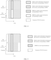
- the transmission sub-resource used by the uplink control information of the URLLC and the transmission sub-resource used by the uplink control information of the eMBB do not overlap in the frequency domain, but partially or completely overlap in the time domain.
- the transmission sub-resource of the uplink control information corresponding to URLLC is sub-resource 1 (that is, the first transmission sub-resource in this application)
- the transmission sub-resource of the uplink control information corresponding to eMBB is sub-resource 2 (that is, the second transmission sub-resource in this application)
- sub-resource 1 and sub-resource 2 do not overlap in the frequency domain.
- sub-resource 1 and sub-resource 2 partially overlap in the time domain; in another possible case, as shown in FIG. 4 and FIG. 6 , sub-resource 1 and sub-resource 2 completely overlap in the time domain.
- the frequency domain starting position of sub-resource 2 is the adjacent position after the frequency domain ending position of sub-resource 1, and its frequency domain ending position is determined by the load and code rate of the uplink control information of the eMBB, or the frequency domain ending position is the frequency domain ending position of the temporary PUCCH resource.
- the temporary URLLC resource includes a resource for transmitting DMRS, and the DMRS is used for receiving and demodulate the uplink control information transmitted in the temporary URLLC resource, that is, the DMRS used for receiving and demodulating includes the DMRS used for the uplink control information corresponding to the URLLC and DMRS used for uplink control information corresponding to eMBB.
- the DMRS used for the uplink control information corresponding to URLLC and the DMRS used for the uplink control information corresponding to eMBB may be generated independently; in another possible case, as shown in FIG. 5 and FIG. 6 , it is also possible to generate a set of DMRS for reception and demodulation, one part of which is used for URLLC and the other part is used for eMBB.
- the steps performed by the terminal device can be independently implemented as a method for determining a transmission resource on the terminal device side
- the steps performed by the network device can be implemented independently as a method for determining a transmission resource on the network device side.
- FIG. 7 shows a structural block diagram of an apparatus for sending uplink control information provided by an exemplary embodiment of the present application.
- the apparatus may be implemented as a terminal device, or may be implemented as a part of the terminal device.
- the apparatus includes: a resource determination module 701;
- the first transmission resource is used for sending all the first uplink control information and all the second uplink control information; or, the first transmission resource is used for sending all the first uplink control information and part of the second uplink control information.
- the first uplink control information and the second uplink control information correspond to different priorities; or, the first uplink control information and the second uplink control information correspond to different services.
- the first transmission sub-resource and the second transmission sub-resource partially overlap in the time domain; or, the first transmission sub-resource and the second transmission sub-resource are completely overlap in the time domain.
- the first transmission sub-resource and the second transmission sub-resource are continuous and do not overlap in the frequency domain.
- the frequency domain starting position of the first transmission sub-resource is the frequency domain starting position of the first transmission resource; the frequency domain ending position of the first transmission sub-resource is determined by the load and code rate of the first uplink control information.
- the frequency domain starting position of the second transmission sub-resource is located after the frequency domain ending position of the first transmission sub-resource and is adjacent to the first transmission sub-resource; the frequency domain ending position of the second transmission sub-resource is determined by the load and code rate of the second uplink control information, or the frequency domain ending position of the second transmission sub-resource is the frequency domain ending position of the first transmission resource.
- the code rate of the first uplink control information is a code rate corresponding to a first temporary transmission resource
- the first temporary transmission resource is determined according to at least one of a PUCCH configuration of the first uplink control information, the load of the first uplink control information or the resource indication of the first uplink control information.
- the code rate of the second uplink control information is a code rate corresponding to a second temporary transmission resource
- the second temporary transmission resource is determined according to at least one of a PUCCH configuration of the second uplink control information, the load of the second uplink control information or the resource indication of the second uplink control information.
- the resource determination module 701 is configured to determine the first temporary transmission resource as the first transmission resource, where the first temporary transmission resource is determined according to at least one of the PUCCH configuration of the first uplink control information, the load of the first uplink control information, or the resource indication of the first uplink control information; or, the resource determination module 701 is configured to determine the second temporary transmission resource as the first transmission resource, where the second temporary transmission resource is determined according to at least one of a PUCCH configuration of the second uplink control information, the load of the second uplink control information or the resource indication of the second uplink control information.
- the first transmission sub-resource includes a resource for sending first reference information, where the first reference information is used for demodulation of the first uplink control information;
- the second transmission sub-resource includes a resource for sending second reference information, where the second reference information is used for demodulation of the second uplink control information.
- the first reference information and the second reference information are generated independently of each other.
- the first reference information and the second reference information are generated in association with each other.
- the first reference information is a part of third reference information
- the second reference information is a remaining part of the third reference information after removing the first reference information
- the third reference information is determined according to configuration information, and the configuration information is used for generating the third reference information.
- FIG. 8 shows a structural block diagram of an apparatus for receiving uplink control information provided by an exemplary embodiment of the present application.
- the apparatus may be implemented as a network device, or may be implemented as a part of a network device, and the device includes: a resource determination module 801;
- the first transmission resource is used for receiving all the first uplink control information and all the second uplink control information; or, the first transmission resource is used for receiving all the first uplink control information and part of the second uplink control information.
- the first uplink control information and the second uplink control information correspond to different priorities; or, the first uplink control information and the second uplink control information correspond to different services.
- the first transmission sub-resource and the second transmission sub-resource partially overlap in the time domain; or, the first transmission sub-resource and the second transmission sub-resource completely overlap in the time domain.
- the first transmission sub-resource and the second transmission sub-resource are continuous and do not overlap in the frequency domain.
- the frequency domain starting position of the first transmission sub-resource is the frequency domain starting position of the first transmission resource; the frequency domain ending position of the first transmission sub-resource is determined by the load and code rate of the first uplink control information.
- the frequency domain starting position of the second transmission sub-resource is located after the frequency domain ending position of the first transmission sub-resource and is adjacent to the first transmission sub-resource; the frequency domain ending position of the second transmission sub-resource is determined by the load and code rate of the second uplink control information, or the frequency domain ending position of the second transmission sub-resource is the frequency domain ending position of the first transmission resource.
- the code rate of the first uplink control information is independent of the code rate of the second uplink control information.
- the code rate of the first uplink control information is a code rate corresponding to a first temporary transmission resource
- the first temporary transmission resource is determined according to at least one of a PUCCH configuration of the first uplink control information, the load of the first uplink control information or the resource indication of the first uplink control information.
- the code rate of the second uplink control information is a code rate corresponding to a second temporary transmission resource
- the second temporary transmission resource is determined according to at least one of a PUCCH configuration of the second uplink control information, the load of the second uplink control information or the resource indication of the second uplink control information.
- the resource determination module 801 is configured to determine a first temporary transmission resource as the first transmission resource, where the first temporary transmission resource is determined according to at least one of the PUCCH configuration of the first uplink control information, the load of the first uplink control information, or the resource indication of the first uplink control information; or, the resource determination module 801 is configured to determine a second temporary transmission resource as the first transmission resource, where the second temporary transmission resource is determined according to at least one of a PUCCH configuration of the second uplink control information, a load of the second uplink control information or the resource indication of the second uplink control information.
- the first transmission sub-resource includes a resource for receiving first reference information, where the first reference information is used for demodulation of the first uplink control information;
- the second transmission sub-resource includes a resource for receiving second reference information, where the second reference information is used for demodulation of the second uplink control information.
- the first reference information and the second reference information are generated independently of each other.
- FIG. 9 shows a schematic structural diagram of a communication device (such as a terminal device or a network device) provided by an exemplary embodiment of the present application.
- the communication device includes: a processor 101, a receiver 102, a transmitter 103, a memory 104 and a bus 105.
- the processor 101 includes one or more processing cores, and the processor 101 executes various functional applications and information processing by running software programs and modules.
- the receiver 102 and the transmitter 103 may be implemented as one communication component, and the communication component may be a communication chip, denoted as a transceiver.
- the memory 104 is connected to the processor 101 through the bus 105.
- the memory 104 may be configured to store at least one instruction, and the processor 101 is configured to execute the at least one instruction, so as to implement various steps in the foregoing method embodiments.
- the memory 104 may be implemented by any type or combination of volatile or non-volatile storage devices including, but not limited to, a magnetic or optical disk, an Electrically-Erasable Programmable Read Only Memory (EEPROM), an Erasable Programmable Read Only Memory (EPROM), a Static Random Access Memory (SRAM), a Read-Only Memory (ROM), a magnetic memory, a flash memory, a Programmable Read-Only Memory (PROM).
- EEPROM Electrically-Erasable Programmable Read Only Memory
- EPROM Erasable Programmable Read Only Memory
- SRAM Static Random Access Memory
- ROM Read-Only Memory
- magnetic memory a magnetic memory
- flash memory a Programmable Read-Only Memory
- the processor and transceiver in the communication device involved in the embodiments of the present application may perform the steps performed by the terminal device in any of the methods shown in FIG. 2 to FIG. 6 above, which will not be repeated here.
- the communication device when the communication device is implemented as a terminal device,
- the processor and transceiver in the communication device involved in the embodiments of the present application may perform the steps performed by the network device in any of the methods shown in the foregoing FIG. 2 to FIG. 6 , which will not be repeated here.
- the communication device when the communication device is implemented as a network device,
- a computer-readable storage medium stores at least one instruction, at least one section of program, code set or instruction set, the at least one instruction, the at least one section of program, the code set or the instruction set is loaded and executed by the processor to implement the method for sending uplink control information or the method for receiving uplink control information provided by the above method embodiments and executed by the communication device.
- a chip is also provided, the chip includes a programmable logic circuit and/or program instructions, and when the chip runs on a computer device, it is used to implement the method for sending uplink control information or the method for receiving uplink control information described in the above aspects.
- a computer program product is also provided, when the computer program product is run on the processor of the computer device, the computer program product causes the computer device to execute the method for sending uplink control information or the method for receiving uplink control information described in the above aspects.
Landscapes
- Engineering & Computer Science (AREA)
- Signal Processing (AREA)
- Computer Networks & Wireless Communication (AREA)
- Mobile Radio Communication Systems (AREA)
Claims (10)
- Verfahren zum Senden von Uplink-Steuerungsinformationen zur Verwendung in einer Endgerätevorrichtung, wobei das Verfahren umfasst:Bestimmen (210) einer ersten Übertragungsressource, wobei die erste Übertragungsressource zum Senden von ersten Uplink-Steuerungsinformationen und zweiten Uplink-Steuerungsinformationen verwendet wird;wobei die erste Übertragungsressource eine erste Übertragungsteilressource und eine zweite Übertragungsteilressource umfasst, wobei die erste Übertragungsteilressource zum Transportieren der ersten Uplink-Steuerungsinformationen verwendet wird und die zweite Übertragungsteilressource zum Transportieren der zweiten Uplink-Steuerungsinformationen verwendet wird; wobei eine den ersten Uplink-Steuerungsinformationen entsprechende Priorität höher als eine den zweiten Uplink-Steuerungsinformationen entsprechende Priorität ist;wobei die erste Übertragungsteilressource und die zweite Übertragungsteilressource in einem Frequenzbereich aneinander angrenzend und nicht überlappend sind;wobei eine Frequenzbereichsanfangsposition der ersten Übertragungsteilressource eine Frequenzbereichsanfangsposition der ersten Übertragungsressource ist;wobei eine Frequenzbereichsendposition der ersten Übertragungsteilressource durch eine Last und eine Coderate der ersten Uplink-Steuerungsinformationen bestimmt wird.
- Verfahren nach Anspruch 1, wobeidie erste Übertragungsressource zum Senden aller ersten Uplink-Steuerungsinformationen und aller zweiten Uplink-Steuerungsinformationen verwendet wird;
oderdie erste Übertragungsressource zum Senden aller ersten Uplink-Steuerungsinformationen und eines Teils der zweiten Uplink-Steuerungsinformationen verwendet wird. - Verfahren nach Anspruch 1 oder 2, wobeidie erste Übertragungsteilressource und die zweite Übertragungsteilressource sich in einem Zeitbereich teilweise überlappen;
oderdie erste Übertragungsteilressource und die zweite Übertragungsteilressource sich im Zeitbereich vollständig überlappen. - Verfahren nach Anspruch 1, wobeieine Frequenzbereichsanfangsposition der zweiten Übertragungsteilressource nach einer Frequenzbereichsendposition der ersten Übertragungsteilressource angeordnet und an die erste Übertragungsteilressource angrenzend ist;eine Frequenzbereichsendposition der zweiten Übertragungsteilressource durch eine Last und eine Coderate der zweiten Uplink-Steuerungsinformationen bestimmt wird oder die Frequenzbereichsendposition der zweiten Übertragungsteilressource eine Frequenzbereichsendposition der ersten Übertragungsressource ist.
- Verfahren nach einem der Ansprüche 1 bis 4, wobei die Coderate der ersten Uplink-Steuerungsinformationen von einer Coderate der zweiten Uplink-Steuerungsinformationen unabhängig ist.
- Verfahren nach Anspruch 5, wobei
die Coderate der ersten Uplink-Steuerungsinformationen eine Coderate ist, die einer ersten temporären Übertragungsressource entspricht, und die erste temporäre Übertragungsressource basierend auf mindestens einem von einer physischen Uplink-Steuerkanal(PUCCH)-Konfiguration der ersten Uplink-Steuerungsinformationen, einer Last der ersten Uplink-Steuerungsinformationen oder einer Ressourcenanzeige der ersten Uplink-Steuerungsinformationen bestimmt wird. - Vorrichtung zum Senden von Uplink-Steuerungsinformationen zur Verwendung in einer Endgerätevorrichtung, wobei die Vorrichtung ein Ressourcenbestimmungsmodul umfasst;wobei das Ressourcenbestimmungsmodul dazu ausgelegt ist, eine erste Übertragungsressource zu bestimmen, und die erste Übertragungsressource zum Senden von ersten Uplink-Steuerungsinformationen und zweiten Uplink-Steuerungsinformationen verwendet wird;wobei die erste Übertragungsressource eine erste Übertragungsteilressource und eine zweite Übertragungsteilressource umfasst, wobei die erste Übertragungsteilressource zum Transportieren der ersten Uplink-Steuerungsinformationen verwendet wird und die zweite Übertragungsteilressource zum Transportieren der zweiten Uplink-Steuerungsinformationen verwendet wird; wobei eine den ersten Uplink-Steuerungsinformationen entsprechende Priorität höher als eine den zweiten Uplink-Steuerungsinformationen entsprechende Priorität ist;wobei die erste Übertragungsteilressource und die zweite Übertragungsteilressource in einem Frequenzbereich aneinander angrenzend und nicht überlappend sind;wobei eine Frequenzbereichsanfangsposition der ersten Übertragungsteilressource eine Frequenzbereichsanfangsposition der ersten Übertragungsressource ist;wobei eine Frequenzbereichsendposition der ersten Übertragungsteilressource durch eine Last und eine Coderate der ersten Uplink-Steuerungsinformationen bestimmt wird.
- Vorrichtung nach Anspruch 7, wobeidie erste Übertragungsressource zum Senden aller ersten Uplink-Steuerungsinformationen und aller zweiten Uplink-Steuerungsinformationen verwendet wird;
oderdie erste Übertragungsressource zum Senden aller ersten Uplink-Steuerungsinformationen und eines Teils der zweiten Uplink-Steuerungsinformationen verwendet wird. - Vorrichtung zum Empfangen von Uplink-Steuerungsinformationen zur Verwendung in einer Netzwerkvorrichtung, wobei die Vorrichtung ein Ressourcenbestimmungsmodul umfasst;wobei das Ressourcenbestimmungsmodul dazu ausgelegt ist, eine erste Übertragungsressource zu bestimmen, und die erste Übertragungsressource zum Empfangen von ersten Uplink-Steuerungsinformationen und zweiten Uplink-Steuerungsinformationen verwendet wird;wobei die erste Übertragungsressource eine erste Übertragungsteilressource und eine zweite Übertragungsteilressource umfasst, wobei die erste Übertragungsteilressource zum Transportieren der ersten Uplink-Steuerungsinformationen verwendet wird und die zweite Übertragungsteilressource zum Transportieren der zweiten Uplink-Steuerungsinformationen verwendet wird; wobei eine den ersten Uplink-Steuerungsinformationen entsprechende Priorität höher als eine den zweiten Uplink-Steuerungsinformationen entsprechende Priorität ist;wobei die erste Übertragungsteilressource und die zweite Übertragungsteilressource in einem Frequenzbereich aneinander angrenzend und nicht überlappend sind;wobei eine Frequenzbereichsanfangsposition der ersten Übertragungsteilressource eine Frequenzbereichsanfangsposition der ersten Übertragungsressource ist;wobei eine Frequenzbereichsendposition der ersten Übertragungsteilressource durch eine Last und eine Coderate der ersten Uplink-Steuerungsinformationen bestimmt wird.
- Vorrichtung nach Anspruch 9, wobeidie erste Übertragungsressource zum Empfangen aller ersten Uplink-Steuerungsinformationen und aller zweiten Uplink-Steuerungsinformationen verwendet wird;
oderdie erste Übertragungsressource zum Empfangen aller ersten Uplink-Steuerungsinformationen und eines Teils der zweiten Uplink-Steuerungsinformationen verwendet wird.
Applications Claiming Priority (1)
| Application Number | Priority Date | Filing Date | Title |
|---|---|---|---|
| PCT/CN2021/071924 WO2022151269A1 (zh) | 2021-01-14 | 2021-01-14 | 上行控制信息的发送方法、接收方法、装置、设备及介质 |
Publications (3)
| Publication Number | Publication Date |
|---|---|
| EP4243533A1 EP4243533A1 (de) | 2023-09-13 |
| EP4243533A4 EP4243533A4 (de) | 2023-12-06 |
| EP4243533B1 true EP4243533B1 (de) | 2024-12-25 |
Family
ID=82446762
Family Applications (1)
| Application Number | Title | Priority Date | Filing Date |
|---|---|---|---|
| EP21918477.7A Active EP4243533B1 (de) | 2021-01-14 | 2021-01-14 | Verfahren zum senden von uplink-steuerungsinformationen und empfangsverfahren und vorrichtungen |
Country Status (4)
| Country | Link |
|---|---|
| US (1) | US20230345495A1 (de) |
| EP (1) | EP4243533B1 (de) |
| CN (1) | CN116420336A (de) |
| WO (1) | WO2022151269A1 (de) |
Families Citing this family (1)
| Publication number | Priority date | Publication date | Assignee | Title |
|---|---|---|---|---|
| US12568472B2 (en) * | 2023-01-23 | 2026-03-03 | Qualcomm Incorporated | Channel state information reporting based on sub-resource pools for sidelink communications |
Family Cites Families (6)
| Publication number | Priority date | Publication date | Assignee | Title |
|---|---|---|---|---|
| CN109392169B (zh) * | 2017-08-04 | 2021-05-07 | 维沃移动通信有限公司 | 一种数据传输方法、终端及基站 |
| CN110225587B (zh) * | 2018-03-01 | 2022-05-10 | 大唐移动通信设备有限公司 | 上行控制信息的传输方法、接收方法、终端、基站及装置 |
| US10863524B2 (en) * | 2018-04-04 | 2020-12-08 | Qualcomm Incorporated | Multiplexing rules for mixed communication protocols |
| CN112425244B (zh) * | 2018-05-11 | 2024-01-12 | Lg电子株式会社 | 在无线通信系统中发送和接收上行链路控制信息的方法及其设备 |
| CN110831219B (zh) * | 2018-08-10 | 2021-08-24 | 北京紫光展锐通信技术有限公司 | 业务冲突处理方法、用户终端及计算机可读存储介质 |
| CN111835480B (zh) * | 2019-07-05 | 2021-11-19 | 维沃移动通信有限公司 | 一种uci传输方法、接收方法、终端和网络设备 |
-
2021
- 2021-01-14 CN CN202180074685.2A patent/CN116420336A/zh active Pending
- 2021-01-14 WO PCT/CN2021/071924 patent/WO2022151269A1/zh not_active Ceased
- 2021-01-14 EP EP21918477.7A patent/EP4243533B1/de active Active
-
2023
- 2023-06-09 US US18/332,186 patent/US20230345495A1/en active Pending
Also Published As
| Publication number | Publication date |
|---|---|
| EP4243533A4 (de) | 2023-12-06 |
| WO2022151269A1 (zh) | 2022-07-21 |
| US20230345495A1 (en) | 2023-10-26 |
| CN116420336A (zh) | 2023-07-11 |
| EP4243533A1 (de) | 2023-09-13 |
Similar Documents
| Publication | Publication Date | Title |
|---|---|---|
| JP7412437B2 (ja) | 情報伝送方法、端末デバイス及びネットワークデバイス | |
| JP2022549595A (ja) | データ送信方法と装置 | |
| EP3379883B1 (de) | Verfahren und mobilstation zur übertragung eines dienstes | |
| JP6328561B2 (ja) | アップリンクでの制御信号に関する通信リソース割当 | |
| WO2020164384A1 (zh) | 一种反馈信息发送方法及装置 | |
| US12261697B2 (en) | Communication method and apparatus | |
| JP2023542690A (ja) | ユーザ装置及びユーザ装置の方法 | |
| US12301507B2 (en) | Data feedback method and apparatus | |
| EP3749045B1 (de) | Verfahren und vorrichtung zur bestimmung eines konfliktfensters | |
| US20230345495A1 (en) | Uplink control information sending method and receiving method, apparatuses, device, and medium | |
| US20240260040A1 (en) | Information transmission method and apparatus, device, and storage medium | |
| CN111885715B (zh) | 信道传输方法及相关设备 | |
| CN116017730B (zh) | 反馈码本确定方法及装置 | |
| CN113647167B (zh) | 一种上行信息传输方法及其装置 | |
| EP4258577A1 (de) | Ressourcenbestimmungsverfahren und -vorrichtung, vorrichtungen und speichermedium | |
| CN117692092A (zh) | 通信方法及设备 |
Legal Events
| Date | Code | Title | Description |
|---|---|---|---|
| STAA | Information on the status of an ep patent application or granted ep patent |
Free format text: STATUS: THE INTERNATIONAL PUBLICATION HAS BEEN MADE |
|
| PUAI | Public reference made under article 153(3) epc to a published international application that has entered the european phase |
Free format text: ORIGINAL CODE: 0009012 |
|
| STAA | Information on the status of an ep patent application or granted ep patent |
Free format text: STATUS: REQUEST FOR EXAMINATION WAS MADE |
|
| 17P | Request for examination filed |
Effective date: 20230609 |
|
| AK | Designated contracting states |
Kind code of ref document: A1 Designated state(s): AL AT BE BG CH CY CZ DE DK EE ES FI FR GB GR HR HU IE IS IT LI LT LU LV MC MK MT NL NO PL PT RO RS SE SI SK SM TR |
|
| A4 | Supplementary search report drawn up and despatched |
Effective date: 20231108 |
|
| RIC1 | Information provided on ipc code assigned before grant |
Ipc: H04W 72/56 20230101ALI20231102BHEP Ipc: H04L 5/00 20060101ALI20231102BHEP Ipc: H04W 72/04 20230101AFI20231102BHEP |
|
| DAV | Request for validation of the european patent (deleted) | ||
| DAX | Request for extension of the european patent (deleted) | ||
| GRAP | Despatch of communication of intention to grant a patent |
Free format text: ORIGINAL CODE: EPIDOSNIGR1 |
|
| STAA | Information on the status of an ep patent application or granted ep patent |
Free format text: STATUS: GRANT OF PATENT IS INTENDED |
|
| INTG | Intention to grant announced |
Effective date: 20240916 |
|
| GRAS | Grant fee paid |
Free format text: ORIGINAL CODE: EPIDOSNIGR3 |
|
| GRAA | (expected) grant |
Free format text: ORIGINAL CODE: 0009210 |
|
| STAA | Information on the status of an ep patent application or granted ep patent |
Free format text: STATUS: THE PATENT HAS BEEN GRANTED |
|
| AK | Designated contracting states |
Kind code of ref document: B1 Designated state(s): AL AT BE BG CH CY CZ DE DK EE ES FI FR GB GR HR HU IE IS IT LI LT LU LV MC MK MT NL NO PL PT RO RS SE SI SK SM TR |
|
| REG | Reference to a national code |
Ref country code: GB Ref legal event code: FG4D |
|
| REG | Reference to a national code |
Ref country code: CH Ref legal event code: EP |
|
| REG | Reference to a national code |
Ref country code: DE Ref legal event code: R096 Ref document number: 602021024047 Country of ref document: DE |
|
| REG | Reference to a national code |
Ref country code: IE Ref legal event code: FG4D |
|
| P01 | Opt-out of the competence of the unified patent court (upc) registered |
Free format text: CASE NUMBER: APP_9891/2025 Effective date: 20250226 |
|
| REG | Reference to a national code |
Ref country code: LT Ref legal event code: MG9D |
|
| PG25 | Lapsed in a contracting state [announced via postgrant information from national office to epo] |
Ref country code: HR Free format text: LAPSE BECAUSE OF FAILURE TO SUBMIT A TRANSLATION OF THE DESCRIPTION OR TO PAY THE FEE WITHIN THE PRESCRIBED TIME-LIMIT Effective date: 20241225 |
|
| PGFP | Annual fee paid to national office [announced via postgrant information from national office to epo] |
Ref country code: DE Payment date: 20250121 Year of fee payment: 5 |
|
| PG25 | Lapsed in a contracting state [announced via postgrant information from national office to epo] |
Ref country code: FI Free format text: LAPSE BECAUSE OF FAILURE TO SUBMIT A TRANSLATION OF THE DESCRIPTION OR TO PAY THE FEE WITHIN THE PRESCRIBED TIME-LIMIT Effective date: 20241225 |
|
| PG25 | Lapsed in a contracting state [announced via postgrant information from national office to epo] |
Ref country code: BG Free format text: LAPSE BECAUSE OF FAILURE TO SUBMIT A TRANSLATION OF THE DESCRIPTION OR TO PAY THE FEE WITHIN THE PRESCRIBED TIME-LIMIT Effective date: 20241225 |
|
| PG25 | Lapsed in a contracting state [announced via postgrant information from national office to epo] |
Ref country code: NO Free format text: LAPSE BECAUSE OF FAILURE TO SUBMIT A TRANSLATION OF THE DESCRIPTION OR TO PAY THE FEE WITHIN THE PRESCRIBED TIME-LIMIT Effective date: 20250325 |
|
| PG25 | Lapsed in a contracting state [announced via postgrant information from national office to epo] |
Ref country code: LV Free format text: LAPSE BECAUSE OF FAILURE TO SUBMIT A TRANSLATION OF THE DESCRIPTION OR TO PAY THE FEE WITHIN THE PRESCRIBED TIME-LIMIT Effective date: 20241225 Ref country code: GR Free format text: LAPSE BECAUSE OF FAILURE TO SUBMIT A TRANSLATION OF THE DESCRIPTION OR TO PAY THE FEE WITHIN THE PRESCRIBED TIME-LIMIT Effective date: 20250326 |
|
| PGFP | Annual fee paid to national office [announced via postgrant information from national office to epo] |
Ref country code: AT Payment date: 20250417 Year of fee payment: 5 |
|
| PGFP | Annual fee paid to national office [announced via postgrant information from national office to epo] |
Ref country code: FR Payment date: 20250122 Year of fee payment: 5 |
|
| PGFP | Annual fee paid to national office [announced via postgrant information from national office to epo] |
Ref country code: GB Payment date: 20250122 Year of fee payment: 5 |
|
| PG25 | Lapsed in a contracting state [announced via postgrant information from national office to epo] |
Ref country code: RS Free format text: LAPSE BECAUSE OF FAILURE TO SUBMIT A TRANSLATION OF THE DESCRIPTION OR TO PAY THE FEE WITHIN THE PRESCRIBED TIME-LIMIT Effective date: 20250325 |
|
| REG | Reference to a national code |
Ref country code: NL Ref legal event code: MP Effective date: 20241225 |
|
| PG25 | Lapsed in a contracting state [announced via postgrant information from national office to epo] |
Ref country code: NL Free format text: LAPSE BECAUSE OF FAILURE TO SUBMIT A TRANSLATION OF THE DESCRIPTION OR TO PAY THE FEE WITHIN THE PRESCRIBED TIME-LIMIT Effective date: 20241225 |
|
| REG | Reference to a national code |
Ref country code: AT Ref legal event code: MK05 Ref document number: 1755224 Country of ref document: AT Kind code of ref document: T Effective date: 20241225 |
|
| PG25 | Lapsed in a contracting state [announced via postgrant information from national office to epo] |
Ref country code: SM Free format text: LAPSE BECAUSE OF FAILURE TO SUBMIT A TRANSLATION OF THE DESCRIPTION OR TO PAY THE FEE WITHIN THE PRESCRIBED TIME-LIMIT Effective date: 20241225 |
|
| PG25 | Lapsed in a contracting state [announced via postgrant information from national office to epo] |
Ref country code: PL Free format text: LAPSE BECAUSE OF FAILURE TO SUBMIT A TRANSLATION OF THE DESCRIPTION OR TO PAY THE FEE WITHIN THE PRESCRIBED TIME-LIMIT Effective date: 20241225 |
|
| PG25 | Lapsed in a contracting state [announced via postgrant information from national office to epo] |
Ref country code: ES Free format text: LAPSE BECAUSE OF FAILURE TO SUBMIT A TRANSLATION OF THE DESCRIPTION OR TO PAY THE FEE WITHIN THE PRESCRIBED TIME-LIMIT Effective date: 20241225 |
|
| PG25 | Lapsed in a contracting state [announced via postgrant information from national office to epo] |
Ref country code: IS Free format text: LAPSE BECAUSE OF FAILURE TO SUBMIT A TRANSLATION OF THE DESCRIPTION OR TO PAY THE FEE WITHIN THE PRESCRIBED TIME-LIMIT Effective date: 20250425 |
|
| PG25 | Lapsed in a contracting state [announced via postgrant information from national office to epo] |
Ref country code: PT Free format text: LAPSE BECAUSE OF FAILURE TO SUBMIT A TRANSLATION OF THE DESCRIPTION OR TO PAY THE FEE WITHIN THE PRESCRIBED TIME-LIMIT Effective date: 20250428 |
|
| PG25 | Lapsed in a contracting state [announced via postgrant information from national office to epo] |
Ref country code: EE Free format text: LAPSE BECAUSE OF FAILURE TO SUBMIT A TRANSLATION OF THE DESCRIPTION OR TO PAY THE FEE WITHIN THE PRESCRIBED TIME-LIMIT Effective date: 20241225 |
|
| PG25 | Lapsed in a contracting state [announced via postgrant information from national office to epo] |
Ref country code: AT Free format text: LAPSE BECAUSE OF FAILURE TO SUBMIT A TRANSLATION OF THE DESCRIPTION OR TO PAY THE FEE WITHIN THE PRESCRIBED TIME-LIMIT Effective date: 20241225 Ref country code: RO Free format text: LAPSE BECAUSE OF FAILURE TO SUBMIT A TRANSLATION OF THE DESCRIPTION OR TO PAY THE FEE WITHIN THE PRESCRIBED TIME-LIMIT Effective date: 20241225 |
|
| PG25 | Lapsed in a contracting state [announced via postgrant information from national office to epo] |
Ref country code: SK Free format text: LAPSE BECAUSE OF FAILURE TO SUBMIT A TRANSLATION OF THE DESCRIPTION OR TO PAY THE FEE WITHIN THE PRESCRIBED TIME-LIMIT Effective date: 20241225 |
|
| PG25 | Lapsed in a contracting state [announced via postgrant information from national office to epo] |
Ref country code: CZ Free format text: LAPSE BECAUSE OF FAILURE TO SUBMIT A TRANSLATION OF THE DESCRIPTION OR TO PAY THE FEE WITHIN THE PRESCRIBED TIME-LIMIT Effective date: 20241225 |
|
| PG25 | Lapsed in a contracting state [announced via postgrant information from national office to epo] |
Ref country code: IT Free format text: LAPSE BECAUSE OF FAILURE TO SUBMIT A TRANSLATION OF THE DESCRIPTION OR TO PAY THE FEE WITHIN THE PRESCRIBED TIME-LIMIT Effective date: 20241225 |
|
| REG | Reference to a national code |
Ref country code: CH Ref legal event code: PL |
|
| PG25 | Lapsed in a contracting state [announced via postgrant information from national office to epo] |
Ref country code: SE Free format text: LAPSE BECAUSE OF FAILURE TO SUBMIT A TRANSLATION OF THE DESCRIPTION OR TO PAY THE FEE WITHIN THE PRESCRIBED TIME-LIMIT Effective date: 20241225 |
|
| PG25 | Lapsed in a contracting state [announced via postgrant information from national office to epo] |
Ref country code: MC Free format text: LAPSE BECAUSE OF FAILURE TO SUBMIT A TRANSLATION OF THE DESCRIPTION OR TO PAY THE FEE WITHIN THE PRESCRIBED TIME-LIMIT Effective date: 20241225 Ref country code: LU Free format text: LAPSE BECAUSE OF NON-PAYMENT OF DUE FEES Effective date: 20250114 |
|
| REG | Reference to a national code |
Ref country code: DE Ref legal event code: R097 Ref document number: 602021024047 Country of ref document: DE |
|
| PG25 | Lapsed in a contracting state [announced via postgrant information from national office to epo] |
Ref country code: DK Free format text: LAPSE BECAUSE OF FAILURE TO SUBMIT A TRANSLATION OF THE DESCRIPTION OR TO PAY THE FEE WITHIN THE PRESCRIBED TIME-LIMIT Effective date: 20241225 |
|
| PG25 | Lapsed in a contracting state [announced via postgrant information from national office to epo] |
Ref country code: BE Free format text: LAPSE BECAUSE OF NON-PAYMENT OF DUE FEES Effective date: 20250131 |
|
| PG25 | Lapsed in a contracting state [announced via postgrant information from national office to epo] |
Ref country code: CH Free format text: LAPSE BECAUSE OF NON-PAYMENT OF DUE FEES Effective date: 20250131 |
|
| REG | Reference to a national code |
Ref country code: BE Ref legal event code: MM Effective date: 20250131 |
|
| PLBE | No opposition filed within time limit |
Free format text: ORIGINAL CODE: 0009261 |
|
| STAA | Information on the status of an ep patent application or granted ep patent |
Free format text: STATUS: NO OPPOSITION FILED WITHIN TIME LIMIT |
|
| 26N | No opposition filed |
Effective date: 20250926 |
|
| PG25 | Lapsed in a contracting state [announced via postgrant information from national office to epo] |
Ref country code: IE Free format text: LAPSE BECAUSE OF NON-PAYMENT OF DUE FEES Effective date: 20250114 |