EP3749045B1 - Verfahren und vorrichtung zur bestimmung eines konfliktfensters - Google Patents
Verfahren und vorrichtung zur bestimmung eines konfliktfensters Download PDFInfo
- Publication number
- EP3749045B1 EP3749045B1 EP18904312.8A EP18904312A EP3749045B1 EP 3749045 B1 EP3749045 B1 EP 3749045B1 EP 18904312 A EP18904312 A EP 18904312A EP 3749045 B1 EP3749045 B1 EP 3749045B1
- Authority
- EP
- European Patent Office
- Prior art keywords
- feedback information
- carrier
- time unit
- length
- network device
- Prior art date
- Legal status (The legal status is an assumption and is not a legal conclusion. Google has not performed a legal analysis and makes no representation as to the accuracy of the status listed.)
- Active
Links
Images


Classifications
-
- H—ELECTRICITY
- H04—ELECTRIC COMMUNICATION TECHNIQUE
- H04W—WIRELESS COMMUNICATION NETWORKS
- H04W74/00—Wireless channel access
- H04W74/08—Non-scheduled access, e.g. ALOHA
-
- H—ELECTRICITY
- H04—ELECTRIC COMMUNICATION TECHNIQUE
- H04W—WIRELESS COMMUNICATION NETWORKS
- H04W74/00—Wireless channel access
- H04W74/08—Non-scheduled access, e.g. ALOHA
- H04W74/0808—Non-scheduled access, e.g. ALOHA using carrier sensing, e.g. carrier sense multiple access [CSMA]
-
- H—ELECTRICITY
- H04—ELECTRIC COMMUNICATION TECHNIQUE
- H04W—WIRELESS COMMUNICATION NETWORKS
- H04W74/00—Wireless channel access
- H04W74/002—Transmission of channel access control information
-
- H—ELECTRICITY
- H04—ELECTRIC COMMUNICATION TECHNIQUE
- H04L—TRANSMISSION OF DIGITAL INFORMATION, e.g. TELEGRAPHIC COMMUNICATION
- H04L1/00—Arrangements for detecting or preventing errors in the information received
- H04L1/12—Arrangements for detecting or preventing errors in the information received by using return channel
- H04L1/16—Arrangements for detecting or preventing errors in the information received by using return channel in which the return channel carries supervisory signals, e.g. repetition request signals
- H04L1/1607—Details of the supervisory signal
- H04L1/1664—Details of the supervisory signal the supervisory signal being transmitted together with payload signals; piggybacking
-
- H—ELECTRICITY
- H04—ELECTRIC COMMUNICATION TECHNIQUE
- H04L—TRANSMISSION OF DIGITAL INFORMATION, e.g. TELEGRAPHIC COMMUNICATION
- H04L1/00—Arrangements for detecting or preventing errors in the information received
- H04L1/12—Arrangements for detecting or preventing errors in the information received by using return channel
- H04L1/16—Arrangements for detecting or preventing errors in the information received by using return channel in which the return channel carries supervisory signals, e.g. repetition request signals
- H04L1/18—Automatic repetition systems, e.g. Van Duuren systems
- H04L1/1812—Hybrid protocols; Hybrid automatic repeat request [HARQ]
- H04L1/1819—Hybrid protocols; Hybrid automatic repeat request [HARQ] with retransmission of additional or different redundancy
-
- H—ELECTRICITY
- H04—ELECTRIC COMMUNICATION TECHNIQUE
- H04L—TRANSMISSION OF DIGITAL INFORMATION, e.g. TELEGRAPHIC COMMUNICATION
- H04L5/00—Arrangements affording multiple use of the transmission path
- H04L5/003—Arrangements for allocating sub-channels of the transmission path
- H04L5/0053—Allocation of signalling, i.e. of overhead other than pilot signals
- H04L5/0055—Physical resource allocation for ACK/NACK
-
- H—ELECTRICITY
- H04—ELECTRIC COMMUNICATION TECHNIQUE
- H04W—WIRELESS COMMUNICATION NETWORKS
- H04W16/00—Network planning, e.g. coverage or traffic planning tools; Network deployment, e.g. resource partitioning or cells structures
- H04W16/14—Spectrum sharing arrangements between different networks
-
- H—ELECTRICITY
- H04—ELECTRIC COMMUNICATION TECHNIQUE
- H04W—WIRELESS COMMUNICATION NETWORKS
- H04W72/00—Local resource management
- H04W72/04—Wireless resource allocation
- H04W72/044—Wireless resource allocation based on the type of the allocated resource
- H04W72/0446—Resources in time domain, e.g. slots or frames
-
- H—ELECTRICITY
- H04—ELECTRIC COMMUNICATION TECHNIQUE
- H04W—WIRELESS COMMUNICATION NETWORKS
- H04W72/00—Local resource management
- H04W72/20—Control channels or signalling for resource management
- H04W72/21—Control channels or signalling for resource management in the uplink direction of a wireless link, i.e. towards the network
-
- H—ELECTRICITY
- H04—ELECTRIC COMMUNICATION TECHNIQUE
- H04W—WIRELESS COMMUNICATION NETWORKS
- H04W74/00—Wireless channel access
- H04W74/08—Non-scheduled access, e.g. ALOHA
- H04W74/0808—Non-scheduled access, e.g. ALOHA using carrier sensing, e.g. carrier sense multiple access [CSMA]
- H04W74/0825—Non-scheduled access, e.g. ALOHA using carrier sensing, e.g. carrier sense multiple access [CSMA] with collision detection
-
- H—ELECTRICITY
- H04—ELECTRIC COMMUNICATION TECHNIQUE
- H04W—WIRELESS COMMUNICATION NETWORKS
- H04W76/00—Connection management
- H04W76/20—Manipulation of established connections
- H04W76/28—Discontinuous transmission [DTX]; Discontinuous reception [DRX]
Definitions
- Embodiments of the present application relate to the field of communications and, more particularly, to a method and a device for determining a contention window.
- the terminal equipment In the licensed-assisted access system based on long term evolution (LAA-LTE), the terminal equipment is provided services with the carrier on the licensed spectrum as the main carrier and the carrier on the unlicensed spectrum as the secondary carrier.
- the communication equipment follows the principle of "Listen Before Talk (LBT)", that is, the communication equipment needs to conduct channel listening before sending signals on the unlicensed spectrum channel, and only can send signals when the channel listening result indicates that the channel is idle. If the channel listening result of the communication device on the channel of unlicensed spectrum indicates that the channel is busy, the communication device cannot send signals.
- LBT Listen Before Talk
- a network device Before starting channel monitoring on the unlicensed carrier, a network device needs to maintain and adjust a length of contention window (CW) used for channel detection (or channel monitoring). For example, the network device can maintain or adjust the length of CW according to a proportion of negative acknowledgement (NACK) in feedback information.
- CW contention window
- NACK negative acknowledgement
- the LTE-LAA system only supports the carrier aggregation (CA) scenario, and the feedback information is transmitted only through the licensed carrier.
- CA carrier aggregation
- the NR system on the unlicensed carrier supports both the CA scenario and the dual connection (DC) and standalone (SA) networking scenarios.
- the feedback information can be transmitted through the licensed carrier or through the unlicensed carrier. Accordingly, how to adjust the length of CW for channel detection is an urgent problem to be solved.
- Related technologies are known from PCT patent publication WO2017166222A1 and WO2017/030310 .
- Embodiments of the application provide a method and a device for adjusting CW being able to adjusting the length of CW according to feedback information corresponding to a physical downlink shared channel (PDSCH) on the unlicensed carrier.
- PDSCH physical downlink shared channel
- a component may be, but is not limited to, a process running on a processor, a processor, an object, an executable file, an execution thread, a program, and/or a computer.
- the application running on the computing device and the computing device may be components.
- One or more components may reside in a process and/or an execution thread, and the components may be localized on one computer and/or distributed on two or more computers.
- these components may be implemented by various computer readable medium having various data structures stored thereon.
- the components may, for example, communicate through local and/or remote processes based on a signal having one or more data packets (e.g., data of two components from interaction with another component in a local system, a distributed system, and/or a network, such as the Internet that interacts with other systems through signals).
- a signal having one or more data packets (e.g., data of two components from interaction with another component in a local system, a distributed system, and/or a network, such as the Internet that interacts with other systems through signals).
- GSM Global System of Mobile Communication
- CDMA Code Division Multiple Access
- WCDMA Wideband Code Division Multiple Access
- GPRS General Packet Radio Service
- LTE Long Term Evolution
- LTE-A advanced long term evolution
- NR New Radio
- evolution system of NR system such as NR-based access to unlicensed spectrum (NR-U) system, Universal Mobile Telecommunication System (UMTS), Wireless Local Area Networks (WLAN), Wireless Fidelity (WiFi) or next-generation communication systems and the like.
- UMTS Universal Mobile Telecommunication System
- WLAN Wireless Local Area Networks
- WiFi Wireless Fidelity
- D2D device to device
- M2M Machine to Machine
- MTC Machine Type Communication
- V2V Vehicle to Vehicle
- CA carrier aggregation
- DC dual connectivity
- SA standalone
- the CA networking scenario may be that the primary carrier is on the licensed spectrum, the secondary carrier is on the unlicensed spectrum, and the primary carrier and the secondary carrier are connected via ideal backhaul.
- the DC networking scenario may be that the primary carrier is on the licensed spectrum, the secondary carrier is on the unlicensed spectrum, and the primary carrier and the secondary carrier are connected via non-ideal backhaul.
- the system on the primary carrier and the system on the secondary carrier may belong to different systems.
- the system on the primary carrier is an LTE system
- the system on the secondary carrier is an NR system.
- the system on the primary carrier may also belong to the same system as the system on the secondary carrier.
- the systems on the primary carrier and the secondary carrier are both LTE systems or NR systems.
- the terminal device may access the network through the system on the unlicensed spectrum.
- the terminal device may also be referred to as user equipment (UE), access terminal, subscriber unit, user station, mobile station, mobile site, remote station, remote terminal, mobile device, user terminal, terminal, wireless communication device, user agent or user device.
- the terminal device may be a station (ST) in WLAN, or may be a cellular phone, a cordless phone, a Session Initiation Protocol (SIP) phone, a Wireless Local Loop (WLL) station, a personal digital processing (PDA) device, a handheld device with wireless communication capabilities, a computing device, other processing devices connected to wireless modems, an in-vehicle devices, a wearable device, or next-generation communication system device, such as a terminal device in the fifth-generation communications (5G) network or in the public land mobile network (PLMN) network that evolves in the future.
- 5G fifth-generation communications
- PLMN public land mobile network
- the terminal device may also be a wearable device.
- the Wearable device may also be referred to as a wearable smart device, which is a general term for wearable devices applying intelligence technology to everyday wear, such as glasses, gloves, watches, clothing and shoes.
- the wearable device may be a portable device that is worn directly on the body or integrated into the user's clothes or accessories.
- the wearable device may not only a hardware device, but may also achieve powerful functions through software support, data interaction, and cloud interaction.
- Generalized wearable smart devices may be full-featured, large-sized, and may achieve complete or partial functions independent of smartphones, such as smart watches or smart glasses.
- Generalized wearable smart devices may only focus on a certain type of application functions, and need to cooperate with other devices such as smartphones, for example, various smart bracelets and smart jewelry for body monitoring.
- the network device may be a device for communicating with a mobile device, and may be an access point (AP) in WLAN, a base transceiver station (BTS) in GSM or CDMA, or a NodeB (NB) in WCDMA, and may also be an evolutional Node B (eNB or eNodeB) in LTE, or a relay station or an access point, or a vehicle-mounted device, a wearable device, and a network device in the future 5G network or in the evolved PLMN network, or the like.
- AP access point
- BTS base transceiver station
- NB NodeB
- eNB evolutional Node B
- eNodeB evolutional Node B
- the network device provides services for the cell.
- the terminal device may communicate with the network device through transmission resources (for example, frequency domain resources or spectrum resources) used in the cell.
- the cell may be a cell corresponding to the network device (e.g., a base station).
- the cell may belong to a macro base station or a base station corresponding to a small cell.
- the small cell herein may include a metro cell, a micro cell, a pico cell, a femto cells, and the like. These small cells have the characteristics of small coverage and low transmission power, and are suitable for providing high-speed data transmission services.
- multiple cells may work on the same frequency at the same time on carriers in LTE system or 5G system.
- the concepts of the carrier and the cell may be considered equivalent.
- CA carrier aggregation
- a secondary carrier is configured for a UE
- Cell ID cell identify
- the concept of carrier and cell may be considered equivalent, for example, UE accessing a carrier is equivalent to accessing a cell.
- the downlink physical channel may include PDCCH (Physical Downlink Control Channel), EPDCCH (Enhanced Physical Downlink Control Channel), and PDSCH (Physical Downlink Shared Channel), PHICH (Physical Hybrid ARQ Indicator Channel), PMCH (Physical Multicast Channel), PBCH (Physical Broadcast Channel), and the like.
- the downlink reference signal may include a downlink synchronization signal, a PT-RS (Phase Tracking Reference Signal), a DMRS (Demodulation Reference Signal), a CSI-RS (Channel State Information -Reference Signal), and the like.
- the downlink synchronization signal may be used by a communication device for network accessing and radio resource management measurement
- the downlink DMRS may be used for demodulation of the downlink channel
- the CSI-RS may be used for downlink channel measurement
- the PT-RS may be used for downlink time-frequency synchronization or phase tracking.
- the embodiments of the present application may include downlink physical channels or downlink reference signals with the same name and different functions as described above, and may also include downlink physical channels or downlink reference signals with different names and the same function as described above. The application is not limited thereto.
- the uplink physical channel in the embodiments of the present application may include a physical random access channel (PRACH), a physical uplink control channel (PUCCH), a physical uplink shared channel (PUSCH) and the like.
- the uplink reference signal may include an uplink demodulation reference signal (DMRS), a sounding reference signal (SRS), a phase tracking reference signal (PT-RS) and the like.
- DMRS uplink demodulation reference signal
- SRS sounding reference signal
- PT-RS phase tracking reference signal
- the uplink DMRS can be used for demodulation of uplink channel
- the SRS can be used for measurement of uplink channel
- the PT-RS can be used for uplink time-frequency synchronization or phase tracking.
- the embodiments of the present application may include uplink physical channels or uplink reference signals with the same name and different functions as described above, and may also include uplink physical channels or uplink reference signals with different names and the same function as described above.
- the application is not limited thereto.
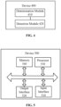
- FIG. 1 is a schematic diagram illustrating a communication system according to an embodiment of the present application.
- the communication system 100 includes a network device 110 and a terminal device 120.
- the network device 110 may be any implementation manner of the foregoing network devices, and the terminal device 120 may be any implementation manner of the foregoing terminal devices, which will not be repeated here.
- the communication system 100 may be a PLMN network, a D2D network, an M2M network, or other networks.
- FIG. 1 is only a simplified schematic diagram of an example, and the network may also include other network devices, which are not shown in FIG. 1 .
- the frequency domain resources used by the network device and the terminal device for wireless communication are frequency domain resources used based on a contention mechanism, for example, the unlicensed spectrum resources.
- the network device and/or the terminal device may detect whether a frequency domain resource with a certain bandwidth (e.g., 20 MHz) is currently in an idle state, in other words, whether the frequency domain resource is used by other devices.
- a frequency domain resource with a certain bandwidth e.g. 20 MHz
- the network device and/or the terminal device may use the frequency domain resource for communication, for example, for uplink transmission or downlink transmission.
- the network device and/or the terminal device cannot use the frequency domain resource.
- the frequency domain resource used by the communication system 100 may also be licensed spectrum resource, that is, the communication system 100 in the embodiments of the present application is a communication system capable of using a licensed frequency band, and each communication device (network device and/or terminal device) in the communication system 100 may use the frequency domain resource of the licensed frequency band in a contention manner.
- the “licensed frequency domain resource” may also be referred to as “licensed spectrum resource” or “licensed carrier”, which refers to frequency domain resources that can be used only after approval by the national or local wireless committee.
- the licensed frequency domain resource cannot be shared between different systems such as LTE system and WiFi system, or, between systems of different service providers.
- the licensed spectrum resources may be delineated by the government's radio management committee and have special-purpose spectrum resources, such as those used by mobile operators, civil aviation, railways, and police. Due to policy exclusivity, the service quality of the licensed spectrum resources can be generally guaranteed, and it is relatively easy to perform scheduling control.
- the frequency domain resource used by the communication system 100 may be unlicensed frequency domain resource.
- the "unlicensed frequency domain resource” may also be referred to as “unlicensed spectrum resource” or “unlicensed carrier”, which refers to resources on unlicensed frequency bands that can be shared by respective communication devices.
- the “resources on unlicensed frequency bands that can be shared” may refer to a situation as follow. Restrictions on use of a specific frequency spectrum may be defined only in some indicators such as the transmission power and out-of-band leakage, so as to ensure basic coexistence requirements are met between multiple devices that jointly use the frequency band. Service provides may use unlicensed frequency band resources to achieve the purpose of network capacity distribution, but need to comply with the regulatory requirements for unlicensed frequency band resources in different regions and different spectrums.
- respective communication devices may utilize the frequency domain resource by adopting a contention manner or a listening method, for example, using a method specified by LBT.
- the unlicensed spectrum resource may be a spectrum resource delineated by relevant government departments, without limiting the radio technology, operating companies, and service life, and without guarantying service quality of the frequency band. Communication devices using the unlicensed spectrum resources only need to meet the requirements of indicators such as transmission power and out-of-band leakage for free use.
- Typical systems that use unlicensed spectrum resources for communication include the Wi-Fi system.
- the unlicensed spectrum resource may include a frequency band around 5 Giga Hertz (GHz), a frequency band around 2.4 GHz, a frequency band around 3.5 GHz, a frequency band around 37 GHz , and a frequency band around 60GHz.
- GHz Giga Hertz
- 2.4 GHz a frequency band around 2.4 GHz
- 3.5 GHz a frequency band around 3.5 GHz
- 37 GHz a frequency band around 37 GHz
- 60GHz Giga Hertz
- FIGs. 2 to 3 are schematic flowcharts of the method for adjusting CW according to an embodiment of the present application, illustrating detailed communication steps or operations of the method, but these steps or operations are only examples.
- the embodiments of the present application may also include other operations or variations of various operations in FIGs. 2 to 3 .
- FIGs. 2 to 3 may be performed in a different order from that shown in FIGs. 2 to 3 , and it may not be necessary to perform all the operations in FIGs. 2 to 3 .
- FIG. 2 is a schematic flowchart illustrating a method 200 for adjusting CW according to an embodiment of the present application. As shown in FIG. 2 , the method 200 may include following steps.
- the network device determines, according to feedback information sent by the terminal device, a length of CW used for channel detection, the feedback information including feedback information corresponding to the PDSCH sent by the network device on a first carrier, and the first carrier being an unlicensed carrier.
- the network device performs channel detection on the first carrier according to the length of CW.
- the network device may determine the length of CW used for channel detection before starting to perform channel detection on the first carrier in the unlicensed carrier. For example, the network device may determine the length of CW according to the feedback information corresponding to the PDSCH sent on the first carrier.
- the feedback information corresponding to the PDSCH includes ACK information and NACK information. For example, if the PDSCH is correctly decoded, the feedback information corresponding to the PDSCH is ACK information; if The PDSCH is not correctly decoded, the feedback information corresponding to the PDSCH is NACK information.
- the ACK information, the NACK information and the like may be sent to the network device through an uplink PUSCH or PUCCH channel.
- the network device may increase the length of CW when the proportion or the number of NACK in the feedback information is relatively large, or decrease the length of CW when the proportion or the number of NACK in the feedback information is relatively small, thereby enabling flexible adjustment of the CW and, further, enabling fair coexistence between different communication systems (e.g., NR-U system, LAA-LTE system and WIFI system).
- different communication systems e.g., NR-U system, LAA-LTE system and WIFI system.
- the network device may perform channel detection according to the determined length of CW for channel detection. If the channel detection is successful, the network device may obtain an opportunity of downlink transmission. Otherwise, the network device cannot perform downlink transmission.
- the opportunity of downlink transmission may include a time unit for continuous transmission of the network device, and one time unit may include one or more subframes, may also be defined as one or more time slots, may also be defined as one or more symbols, may also be defined as one or more mini-slots, or the like.
- a start time unit and/or an end time unit of one downlink transmission opportunity may be a complete time unit, a partial time unit or the like.
- the network device may perform transmission of downlink physical channel on the first carrier.
- the number of the terminal devices may be one or more, that is, the feedback information used for determining the length of CW may be fed back by one or more terminal devices. Embodiments of the present application are not limited thereto.
- the feedback information may include at least one of hybrid automatic repeat request (HARQ) information, channel quality indication (CQI), precoding matrix indication (PMI) or codebook, rank indication (RI), scheduling request (SR), or other feedback information fed back by the terminal device.
- HARQ hybrid automatic repeat request
- CQI channel quality indication
- PMI precoding matrix indication
- RI rank indication
- SR scheduling request
- the HARQ information includes at least one of the following states: positive acknowledgment (ACK), negative acknowledgment (NACK), discontinuous transmission (DTX) information, NACK or DTX information and any information.
- ACK positive acknowledgment
- NACK negative acknowledgment
- DTX discontinuous transmission
- the terminal device if the terminal device correctly receives the PDSCH sent by the network device, the ACK is fed back. Alternatively, if the terminal device does not correctly receive the PDSCH sent by the network device, the NACK is fed back. Alternatively, if the terminal device does not receive the uplink grant (UL-grant) indicating the PDSCH, the terminal device may not feed back or may feed back the discontinuous transmission (DTX) information to the network device.
- UL-grant uplink grant
- DTX discontinuous transmission
- the feedback information may be transmitted through the first carrier, that is, the PDSCH and the feedback information corresponding to the PDSCH may be transmitted through the same unlicensed carrier.
- the feedback information may be transmitted through a second carrier other than the first carrier.
- the feedback information may be transmitted through an unlicensed carrier other than the first carrier, that is, the carriers for transmitting the feedback information corresponding to the PDSCH and the PDSCH may be different.
- the feedback information may also be transmitted through a licensed carrier, that is, the network device may transmit the PDSCH through the unlicensed carrier, and the terminal device may transmit the feedback information corresponding to the PDSCH through the licensed carrier.
- the method 200 may further include:
- the unlicensed carrier may be the same unlicensed carrier as the first carrier, or may be an unlicensed carrier different from the first carrier. If the network device does not receive feedback information on the unlicensed carrier, the feedback information is not counted, that is, a count value of NACK is not increased. Alternatively, if the network device receives NACK on the unlicensed carrier, the count value of NACK is increased. Alternatively, if the network device receives any one of DTX, NACK/DTX or any information on the unlicensed carrier, such feedback information may be counted as NACK, and the count value of NACK is increased.
- the network device may determine the count value of NACK according to a status of the feedback information returned by the terminal device 2.
- the feedback information is ACK
- the NACK is not counted; or if the feedback information is any one of NACK, DTX, NACK/DTX or any, then the feedback information is determined as NACK, and the count value of NACK is increased.
- S210 may specifically include:
- the network device may increase the length of CW, that is, set aside longer time of communication resources for data communication by other communication systems.
- the proportion or the number of NACK in the feedback information is less than the preset threshold, a load on the channel may be small. So the network device may reduce the length of CW, that is, access to the channel for data communication, thereby enabling fair coexistence between multiple communication systems.
- the length of CW may be linearly increased, for example, by adding a fixed window length based on the original length of CW, or by multiplying the original length of CW by a certain ratio (e.g., 1.1 or 1.2).
- the length of CW may also be increased exponentially, for example, by a power of 2.
- the length of CW may be linearly decreased or exponentially decreased.
- the length of CW may also be decreased by being restored to an initial value of the CW.
- Embodiments of the application are not limited thereto.
- the first preset value may be 80%, or may be other ratios, which is not limited by the embodiments of the present application.
- the feedback information includes all or part of feedback information transmitted in a physical uplink control channel PUCCH on a first time unit, the first time unit being on a time unit the first carrier, or a time unit on a second carrier other than the first carrier.
- the feedback information may be transmitted in a PUCCH on the first time unit, and the PUCCH may be transmitted on an unlicensed carrier or may be transmitted on a licensed carrier.
- the feedback information that is transmitted in the PUCCH on the first time unit may include the feedback information corresponding to the PDSCH on the unlicensed carrier, or may also include the feedback information corresponding to the PDSCH on the licensed carrier.
- the feedback information used for adjusting the length of CW includes only the feedback information corresponding to the PDSCH on the unlicensed carrier, that is, not all the feedback information transmitted on the PUCCH can be used for adjusting the length of CW.
- the first time unit may be a time unit on the first carrier, that is, the feedback information may be transmitted on the first time unit on the first carrier.
- the first time unit may also be a time unit on a second carrier different from the first carrier, that is, the feedback information may be transmitted on the first time unit on the second carrier.
- the second carrier is an unlicensed carrier different from the first carrier, or the second carrier is a licensed carrier.
- the first time unit may be any time domain resource used for transmitting the PUCCH, for example, one or more time slots, or one or more subframes, or one or more symbols, or the like. Embodiments of the present application are not limited thereto.
- the time length of one PUCCH may also be one or more symbols.
- the number of symbols included in one PUCCH may be one of 1, 2, 4, 5, 6, 7, 8, 9, 10, 11, 12, 13, 14.
- the length of one PUCCH is one or two symbols, it is called a short PUCCH.
- the first time unit may include:
- the latest uplink transmission before the network device determines the length of CW can be understood as the latest uplink transmission (referred to as uplink transmission 1) before the adjustment of CW, that is, there is no uplink transmission between the uplink transmission 1 and the adjustment of CW.
- the second to last uplink transmission before the network device determines the length of CW is the latest uplink transmission(referred to as uplink transmission 2) before the uplink transmission 1, that is, there is no uplink transmission between the uplink transmission 1 and the uplink transmission 2.
- the PUCCH transmitted by the first time unit may be one or more.
- multiple terminal devices may simultaneously transmit the PUCCH on the first time unit, that is, the time unit used by the multiple terminals to transmit the PUCCH is the same, while the time domain location, and/or the frequency domain location, and/or the code domain location may be different.
- a terminal device 1 transmits a PUCCH through the first time unit on the first carrier
- a terminal device 2 transmits a PUCCH through the first time unit on a carrier other than the first carrier (e.g., another unlicensed carrier or a licensed carrier).
- the terminal device 1 and the terminal device 2 respectively transmit respective PUCCHs by code division on the same frequency domain resource through the first time unit on the first carrier.
- the first time unit may be a time unit all used for PUCCH transmission, or may be a time unit partially used for PUCCH transmission, which is not limited in this application.
- the first time unit includes:
- the first time unit is a time unit in which a PUCCH demodulation result is effectively obtained.
- the network device has completed demodulation of the PUCCH transmitted on the first time unit before determining the length of CW, so that the size of CW can be determined based on the demodulation result.
- the network device schedules PUCCH transmissions on the headmost time unit and the last time unit in uplink transmission 1, and also schedules PUCCH transmissions on the headmost time unit and the last time unit in uplink transmission 2.
- the network device determines the CW for channel detection after the end of the uplink transmission 1, so as to perform downlink transmission after the channel detection succeeds.
- the first time unit may include at least one of the time units in which the PUCCH demodulation has been completed (i.e., the headmost time unit in the uplink transmission 1, the headmost time unit and the last time unit in the uplink transmission 2).
- the first time unit includes the headmost time unit in the uplink transmission 1 and/or the last time unit in the uplink transmission 2.
- the feedback information includes all or part of feedback information transmitted in a physical uplink shared channel (PUSCH) on a second time unit, the second time unit being a time unit on the first carrier or a time unit on a third carrier other than the first carrier.
- PUSCH physical uplink shared channel
- the feedback information may be transmitted in the PUSCH on the second time unit, where the PUSCH may be transmitted on an unlicensed carrier, or may be transmitted on a licensed carrier.
- the feedback information transmitted in the PUSCH on the second time unit may include the feedback information corresponding to the PDSCH on the licensed carrier, or may also include the feedback information corresponding to the PDSCH on the licensed carrier.
- the feedback information used for adjusting the length of CW may include only the feedback information corresponding to the PDSCH on the unlicensed carrier, that is, not all the feedback information transmitted on the PUSCH may be used for adjusting the length of CW.
- the second time unit may be a time unit on the first carrier, that is, the feedback information may be transmitted on the second time unit on the first carrier.
- the second time unit may also be a time unit on a third carrier different from the first carrier, that is, the feedback information may be transmitted on the second time unit of an unlicensed carrier different from the first carrier.
- the feedback information may be transmitted on the second time unit on a licensed carrier.
- the second time unit may be any time domain resource for transmitting the PUSCH, for example, one or more time slots, or one or more subframes, or one or more symbols, or the like. Embodiments of the present application are not limited thereto.
- the second time unit includes:
- the PUSCH carrying the feedback information transmitted by the second time unit may be one or more.
- multiple terminal devices may simultaneously transmit the PUSCH on the second time unit, that is, the time unit used by the terminal devices for transmitting the PUSCH carrying the feedback information is the same, while the time domain location and/or the frequency domain location may be different.
- the terminal device 1 transmits a PUSCH carrying feedback information through the second time unit on the first carrier
- the terminal device 2 transmits a PUSCH carrying feedback information through the second time unit on a carrier other than the first carrier (e.g., another unlicensed carrier or a licensed carrier).
- the terminal device 1 transmits the PUSCH carrying the feedback information through the first 7 symbols on the second time unit, and the terminal device 2 transmits the PUSCH carrying the feedback information through the last 7 symbols on the second time unit.
- the second time unit may be a time unit all used for PUSCH transmission, or may be a time unit partially used for PUSCH transmission, which is not limited in this application.
- the feedback information may be carried on only part of the PUSCH in the PUSCH transmitted on the second time unit, which is not limited in this application.
- the second time unit includes:
- the second time unit is a time unit in which a demodulation result of the feedback information carried on the PUSCH is effectively obtained.
- the network device has completed the demodulation of feedback information transmitted on the second time unit before determining the length of CW, so that the size of CW can be determined based on the demodulation result.
- the network device schedules transmissions of PUSCHs carrying feedback information on the headmost time unit and the last time unit in uplink transmission 1, and also schedules transmissions of PUSCHs carrying feedback information on the headmost time unit and the last time unit in uplink transmission 2.
- the network device determines the CW for channel detection after the end of the uplink transmission 1, so as to perform downlink transmission after the channel detection succeeds.
- the second time unit may include at least one of the time units in which the demodulation of feedback information has been completed (i.e., the headmost time unit in the uplink transmission 1, the headmost time unit and the last time unit in the uplink transmission 2).
- the second time unit includes the headmost time unit in the uplink transmission 1 and/or the last time unit in the uplink transmission 2.
- the feedback information includes feedback information corresponding to PDSCH on a third time unit.
- the network device may send the PDSCH to the terminal device through the third time unit on the first carrier. Furthermore, the network device may receive, on the first time unit of the first carrier or the second carrier, feedback information corresponding to the PDSCH which is transmitted in PUCCH by the terminal device. Alternatively, the network device may also receive, on second first time unit of the first carrier or the third carrier, feedback information corresponding to the PDSCH which is transmitted in PUCCH by the terminal device. Then the network device may determine the length of CW according to the state of the feedback information, and further, may perform channel detection according to the length of CW.
- the feedback information corresponding to the PDSCH on the third time unit may be transmitted through a licensed carrier, or may be transmitted through an unlicensed carrier.
- the feedback information corresponding to the PDSCH may be transmitted through PUCCH or a PUSCH. Therefore, the PUCCH or the PUSCH may be transmitted through an unlicensed carrier or a licensed carrier.
- the third time unit may be a time unit all used for PDSCH transmission, or may be a time unit partially used for PDSCH transmission, which is not limited in this application.
- the third time unit may include:
- the third time unit is a time unit in which the feedback information corresponding to the PDSCH is effectively obtained.
- the network device has completed demodulation of HARQ feedback information corresponding to the PDSCH transmitted on the third time unit before determining the length of CW, so that the size of CW can be determined according to the demodulation result.
- the feedback information includes feedback information corresponding to the PDSCH transmitted on the headmost time unit in the downlink transmission 1.
- the feedback information includes feedback information corresponding to the PDSCH transmitted on the two preceding time units in the downlink transmission 1.
- the feedback information used for adjusting the length of CW may be transmitted in PUCCH or PUSCH, where the PUCCH or the PUSCH may be transmitted through an unlicensed carrier, or may be transmitted through a licensed carrier.
- the feedback information that is transmitted by the PUCCH or the PUSCH on the unlicensed carrier may be the feedback information corresponding to the PDSCH on the unlicensed carrier, or may be the feedback information corresponding to the PDSCH on the licensed carrier.
- the feedback information used for adjusting the length of CW may include only feedback information corresponding to the PDSCH on the unlicensed carrier.
- the uplink transmission 2 includes subframes #6 to #9
- the downlink transmission 1 includes subframes #0 to #3
- the uplink transmission 1 includes subframes #3 to #6, where subframe #3 has both downlink transmission and uplink transmission.
- subframes #6 and #9 are subframes for transmitting PUCCH
- subframes #7 and #8 are subframes for transmitting PUSCH carrying feedback information.
- subframes #3 and #6 are subframes for transmitting PUCCH
- subframes #4 and #5 are subframes for transmitting PUSCH carrying feedback information.
- subframes #0 and #3 are partial subframes for transmitting PDSCH
- subframes #1 and #2 are complete subframes for transmitting PDSCH.
- the network device may obtain feedback information corresponding to the PDSCH on the first carrier by using at least one of the following manners (1)-(5), thereby determining CW2 for channel detection:
- FIG. 4 is a block diagram illustrating a device for adjusting CW according to an embodiment of the present application.
- the device 400 of FIG. 4 includes:
- the feedback information includes all or part of feedback information transmitted in a physical uplink control channel (PUCCH) on a first time unit, the first time unit being a time unit on the first carrier or a time unit on a second carrier other than the first carrier.
- PUCCH physical uplink control channel
- the second carrier is an unlicensed carrier different from the first carrier; or the second carrier is a licensed carrier.
- the first time unit includes:
- the first time unit includes:
- the feedback information includes all or part of feedback information transmitted in a physical uplink shared channel (PUSCH) on a second time unit, the second time unit being a time unit on the first carrier or a time unit on a third carrier other than the first carrier.
- PUSCH physical uplink shared channel
- the third carrier is an unlicensed carrier different from the first carrier; or the third carrier is a licensed carrier.
- the second time unit includes:
- the second time unit includes:
- the feedback information includes feedback information corresponding to a PDSCH on a third time unit.
- the third time unit includes:
- the feedback information corresponding to the PDSCH on the third time unit is transmitted through a licensed carrier.
- the feedback information is HARQ information
- the HARQ information includes at least one of following states: positive acknowledgment (ACK), negative acknowledgment (NACK), discontinuous transmission (DTX) information, NACK or DTX information and any information.
- the determination module is further configured to:
- the determination module is further configured to:
- the device 400 may correspond to (for example, may be provided in or implemented as) the network device described in the foregoing method 200, and each module or unit in the device 400 is configured to execute respective operations or processes performed by the network device in the foregoing method 200, detail of which is omitted here for the sake of avoiding redundancy.
- an embodiment of the present application further provides a device 500 for adjusting CW, and the device 500 may be the device 400 in FIG. 4 , which can be configured to execute operations of the network device corresponding to the method 200 in FIG. 2 .
- the device 500 includes an input interface 510, an output interface 520, a processor 530, and a memory 540.
- the input interface 510, the output interface 520, the processor 530, and the memory 540 may be connected through a bus system.
- the memory 540 is configured to store programs, instructions or codes.
- the processor 530 is configured to execute programs, instructions, or codes in the memory 540 to control the input interface 510 to receive signals, control the output interface 520 to send signals, and complete operations in the foregoing method embodiments.
- the processor 530 may be a central processing unit ("CPU"), and the processor 530 may also be other general-purpose processors or digital signal processors (DSP), application specific integrated circuit (ASIC), field programmable gate array (FPGA) or other programmable logic devices, discrete gates or transistor logic devices, discrete hardware components, or the like.
- the general-purpose processor may be a microprocessor or the processor may also be any conventional processor or the like.
- the memory 540 may include a read-only memory and a random access memory, and provide instructions and data to the processor 530. A portion of the memory 540 may also include non-volatile random access memory. For example, the memory 540 may also store information on the type of device.
- content of the above method may be completed by an integrated logic circuit of hardware in the processor 530 or instructions in the form of software.
- the content of the method disclosed in conjunction with the embodiments of the present application may be directly embodied and completed by a hardware processor, or may be implemented and completed by a combination of hardware and software modules in the processor.
- the software module may be located in a mature storage medium in the art, such as random access memory, flash memory, read-only memory, programmable read-only memory, electrically erasable programmable memory, or registers.
- the storage medium may be located in the memory 540, and the processor 530 reads the information from the memory 540 and completes the content of the above method in combination with its hardware. In order to avoid repetition, details thereof are not described here.
- the determination module 410 included in the device 400 in FIG. 4 may be implemented by the processor 530 in FIG. 5
- the detection module 420 included in the device 400 in FIG. 4 may be implemented by the input interface 510 and the output interface 520 described in FIG. 5 .
- Embodiments of the present application also provide a computer-readable storage medium that stores one or more programs, the one or more programs include instructions.
- the instructions may cause, when executed by a portable electronic device that includes multiple application programs, the portable electronic device to implement the method according to the embodiments shown in FIGs. 2 to 3 .
- An embodiment of the present application also proposes a computer program including instructions.
- the computer program may cause, when executed by a computer, the computer to implement the corresponding flow of the method according to the embodiments shown in FIGs. 2 to 3 .
- the disclosed system, device, and method may be implemented in other manners.
- the device embodiments described above are only schematic.
- the division of the units is only a logical function division, and there may be other divisions in actual implementation, for example, multiple units or components may be combined with each other or may be integrated into another system, or some features can be ignored or not implemented.
- the displayed or discussed mutual coupling or direct coupling or communication connection may be indirect coupling or communication connection through some interfaces, devices or units, and may be in electrical, mechanical, or other forms.
- the units described as separate components may be or may not be physically separated, and the components displayed as units may be or may not be physical units. In other words, they may be located in one place, or may be distributed at multiple network units. Some or all of the units may be selected according to actual needs to achieve the purpose of the solution of this embodiment.
- each functional unit in each embodiment of the present application may be integrated into one processing unit, or each unit may exist alone physically, or two or more units may be integrated into one unit.
- the function is implemented in the form of a software functional unit and sold or used as an independent product, it can be stored in a computer-readable storage medium.
- the technical solution of the present application may be essentially or a part that contributes to the prior art or a part of the technical solution may be embodied in the form of a software product, and the computer software product is stored in a storage medium, including several instructions to enable a computer device (which may be a personal computer, server, network device, or the like) to perform all or part of the steps of the methods described in the embodiments of the present application.
- the foregoing storage medium may include U disk, mobile hard disk, read-only memory (ROM), random access memory (RAM), magnetic disk or optical disk and other media that can store program codes .
Landscapes
- Engineering & Computer Science (AREA)
- Signal Processing (AREA)
- Computer Networks & Wireless Communication (AREA)
- Mobile Radio Communication Systems (AREA)
Claims (8)
- Verfahren zum Bestimmen eines Konfliktfensters, CW, umfassend:Bestimmen (S210), durch eine Netzwerkvorrichtung gemäß durch eine Endgerätvorrichtung gesandten Rückmeldungsinformationen, einer für Kanaldetektion verwendeten CW-Länge; undDurchführen (S220), durch die Netzwerkvorrichtung, von Kanaldetektion auf dem ersten Träger gemäß der CW-Länge,dadurch gekennzeichnet, dass die Rückmeldungsinformationen in einem physikalischen Aufwärtsstrecken-Steuerkanal, PUCCH, auf einer ersten Zeiteinheit eines ersten Trägers übertragene Rückmeldungsinformationen umfassen, wobei die erste Zeiteinheit eine vorderste Zeiteinheit ist, verwendet zum Übertragen des PUCCH in einer letzten Aufwärtsstreckenübertragung, bevor die Netzwerkvorrichtung die CW-Länge bestimmt; oder die Rückmeldungsinformationen in einem physikalischen gemeinsam genutzten Aufwärtsstreckenkanal, PUSCH, auf einer zweiten Zeiteinheit des ersten Trägers übertragene Rückmeldungsinformationen umfassen, wobei die zweite Zeiteinheit eine vorderste Zeiteinheit ist, verwendet zum Übertragen des PUSCH einschließlich der Rückmeldungsinformationen in der letzten Aufwärtsstreckenübertragung, bevor die Netzwerkvorrichtung die CW-Länge bestimmt, unddie Rückmeldungsinformationen Rückmeldungsinformationen korrespondierend mit einem physikalischen gemeinsam genutzten Abwärtsstreckenkanal, PDSCH, auf einer vordersten Zeiteinheit in einer letzten Abwärtsstreckenübertragung umfassen, durchgeführt auf einem zweiten Träger, bevor die Netzwerkvorrichtung die CW-Länge bestimmt, wobei der erste Träger und der zweite Träger ein gleicher nicht lizenzierter Träger sind.
- Verfahren nach Anspruch 1, wobei die Rückmeldungsinformationen Informationen einer hybriden automatischen Wiederholungsanforderung, HARQ, sind und die HARQ-Informationen umfassen
positive Bestätigung, ACK, und negative Bestätigung, NACK. - Verfahren nach Anspruch 1 oder 2, wobei Bestimmen, durch die Netzwerkvorrichtung gemäß den durch die Endgerätvorrichtung gesandten Rückmeldungsinformationen, der für Kanaldetektion verwendeten CW-Länge umfasst:Bestimmen, durch die Netzwerkvorrichtung, die CW-Länge zu vergrößern, wenn ein in den Rückmeldungsinformationen enthaltener NACK-Anteil größer als ein oder gleich einem ersten im Voraus eingestellten Wert ist oder eine in den Rückmeldungsinformationen enthaltene NACK-Anzahl größer als ein oder gleich einem zweiten im Voraus eingestellten Wert ist; oderBestimmen, durch die Netzwerkvorrichtung, die CW-Länge zu verringern oder beizubehalten, wenn der in den Rückmeldungsinformationen enthaltene NACK-Anteil kleiner als der erste im Voraus eingestellte Wert ist oder die in den Rückmeldungsinformationen enthaltene NACK-Anzahl kleiner als der zweite im Voraus eingestellte Wert ist.
- Verfahren nach einem der Ansprüche 1 bis 3, ferner umfassend:
Bewirken, dass die Rückmeldungsinformationen nicht gezählt werden, wenn die Netzwerkvorrichtung die Rückmeldungsinformationen auf dem nicht lizenzierten Träger nicht detektiert. - Vorrichtung zum Bestimmen eines Konfliktfensters, CW, umfassend:ein Bestimmungsmodul, konfiguriert zum Bestimmen, gemäß durch eine Endgerätvorrichtung gesandten Rückmeldungsinformationen, einer für Kanaldetektion verwendeten CW-Länge; undein Detektionsmodul, konfiguriert zum Durchführen von Kanaldetektion auf dem ersten Träger gemäß der CW-Länge,dadurch gekennzeichnet, dass die Rückmeldungsinformationen in einem physikalischen Aufwärtsstrecken-Steuerkanal, PUCCH, auf einer ersten Zeiteinheit eines ersten Trägers übertragene Rückmeldungsinformationen umfassen, wobei die erste Zeiteinheit eine vorderste Zeiteinheit ist, verwendet zum Übertragen des PUCCH in einer letzten Aufwärtsstreckenübertragung, bevor die Netzwerkvorrichtung die CW-Länge bestimmt; oder die Rückmeldungsinformationen in einem physikalischen gemeinsam genutzten Aufwärtsstreckenkanal, PUSCH, auf einer zweiten Zeiteinheit des ersten Trägers übertragene Rückmeldungsinformationen umfassen, wobei die zweite Zeiteinheit eine vorderste Zeiteinheit ist, verwendet zum Übertragen des PUSCH einschließlich der Rückmeldungsinformationen in der letzten Aufwärtsstreckenübertragung, bevor die Netzwerkvorrichtung die CW-Länge bestimmt, unddie Rückmeldungsinformationen Rückmeldungsinformationen korrespondierend mit einem physikalischen gemeinsam genutzten Abwärtsstreckenkanal, PDSCH, auf einer vordersten Zeiteinheit in einer letzten Abwärtsstreckenübertragung umfassen, durchgeführt auf einem zweiten Träger, bevor die Netzwerkvorrichtung die CW-Länge bestimmt, wobei der erste Träger und der zweite Träger ein gleicher nicht lizenzierter Träger sind.
- Vorrichtung nach Anspruch 5, wobei die Rückmeldungsinformationen Informationen einer hybriden automatischen Wiederholungsanforderung, HARQ, sind und die HARQ-Informationen umfassen:
positive Bestätigung, ACK, und negative Bestätigung, NACK. - Vorrichtung nach Anspruch 5 oder 6, wobei das Bestimmungsmodul konfiguriert ist zum:Bestimmen, die CW-Länge zu vergrößern, wenn ein in den Rückmeldungsinformationen enthaltener NACK-Anteil größer als ein oder gleich einem ersten im Voraus eingestellten Wert ist oder eine in den Rückmeldungsinformationen enthaltene NACK-Anzahl größer als ein oder gleich einem zweiten im Voraus eingestellten Wert ist; oderBestimmen, die CW-Länge zu verringern oder beizubehalten, wenn der in den Rückmeldungsinformationen enthaltene NACK-Anteil kleiner als der erste im Voraus eingestellte Wert ist oder die in den Rückmeldungsinformationen enthaltene NACK-Anzahl kleiner als der zweite im Voraus eingestellte Wert ist.
- Vorrichtung nach einem der Ansprüche 5 bis 7, wobei das Bestimmungsmodul ferner konfiguriert ist zum:
Bewirken, dass die Rückmeldungsinformationen nicht gezählt werden, wenn die Netzwerkvorrichtung die Rückmeldungsinformationen auf dem nicht lizenzierten Träger nicht detektiert.
Applications Claiming Priority (1)
| Application Number | Priority Date | Filing Date | Title |
|---|---|---|---|
| PCT/CN2018/075063 WO2019148443A1 (zh) | 2018-02-02 | 2018-02-02 | 确定竞争窗口的方法和设备 |
Publications (3)
| Publication Number | Publication Date |
|---|---|
| EP3749045A1 EP3749045A1 (de) | 2020-12-09 |
| EP3749045A4 EP3749045A4 (de) | 2020-12-23 |
| EP3749045B1 true EP3749045B1 (de) | 2025-04-30 |
Family
ID=67480004
Family Applications (1)
| Application Number | Title | Priority Date | Filing Date |
|---|---|---|---|
| EP18904312.8A Active EP3749045B1 (de) | 2018-02-02 | 2018-02-02 | Verfahren und vorrichtung zur bestimmung eines konfliktfensters |
Country Status (7)
| Country | Link |
|---|---|
| US (2) | US11350446B2 (de) |
| EP (1) | EP3749045B1 (de) |
| JP (1) | JP7117387B6 (de) |
| KR (1) | KR102512147B1 (de) |
| CN (2) | CN113438745A (de) |
| AU (1) | AU2018406782B2 (de) |
| WO (1) | WO2019148443A1 (de) |
Families Citing this family (4)
| Publication number | Priority date | Publication date | Assignee | Title |
|---|---|---|---|---|
| US11272539B2 (en) | 2018-08-09 | 2022-03-08 | Ofinno, Llc | Channel access and bandwidth part switching |
| US11272540B2 (en) * | 2018-08-09 | 2022-03-08 | Ofinno, Llc | Channel access and uplink switching |
| US11917684B2 (en) * | 2019-01-11 | 2024-02-27 | Lg Electronics Inc. | Channel access procedure by apparatus in unlicensed band |
| WO2024071831A1 (ko) * | 2022-09-26 | 2024-04-04 | 한국전자통신연구원 | 사이드링크 통신에서 채널 접속을 위한 방법 및 장치 |
Citations (1)
| Publication number | Priority date | Publication date | Assignee | Title |
|---|---|---|---|---|
| WO2017030310A1 (ko) * | 2015-08-14 | 2017-02-23 | 한국전자통신연구원 | 면허 및 비면허 대역들을 지원하는 네트워크에서 통신 노드의 동작 방법 |
Family Cites Families (8)
| Publication number | Priority date | Publication date | Assignee | Title |
|---|---|---|---|---|
| CN105578607B (zh) * | 2014-11-05 | 2019-12-10 | 电信科学技术研究院 | 一种进行载波调度的方法和设备 |
| KR102059000B1 (ko) * | 2015-05-12 | 2019-12-24 | 엘지전자 주식회사 | 비면허 대역을 지원하는 무선접속시스템에서 경쟁 윈도우 크기를 조정하는 방법 및 이를 지원하는 장치 |
| WO2016182398A1 (en) * | 2015-05-14 | 2016-11-17 | Samsung Electronics Co., Ltd. | Method and apparatus for managing contention window in wireless communication system |
| US9882700B2 (en) * | 2015-06-30 | 2018-01-30 | Sharp Kabushiki Kaisha | Systems and methods for backoff procedures for licensed-assisted access |
| EP3366075B1 (de) * | 2015-10-19 | 2020-07-15 | Intel IP Corporation | Planung von uplink-übertragungen für ein benutzergerät (ue) |
| EP3726917B1 (de) * | 2016-02-04 | 2022-11-02 | Huawei Technologies Co., Ltd. | Verfahren und vorrichtung zur bestimmung von konfliktfensterinformationen |
| JP6702603B2 (ja) * | 2016-03-31 | 2020-06-03 | ホアウェイ・テクノロジーズ・カンパニー・リミテッド | クリアチャネルアセスメントにおけるコンテンションウィンドウサイズを決定するための方法および装置 |
| CN107295695A (zh) * | 2016-04-01 | 2017-10-24 | 索尼公司 | 电子装置、信息处理设备和信息处理方法 |
-
2018
- 2018-02-02 CN CN202110715823.2A patent/CN113438745A/zh active Pending
- 2018-02-02 EP EP18904312.8A patent/EP3749045B1/de active Active
- 2018-02-02 WO PCT/CN2018/075063 patent/WO2019148443A1/zh not_active Ceased
- 2018-02-02 JP JP2020541507A patent/JP7117387B6/ja active Active
- 2018-02-02 KR KR1020207024383A patent/KR102512147B1/ko active Active
- 2018-02-02 AU AU2018406782A patent/AU2018406782B2/en active Active
- 2018-02-02 CN CN201880087063.1A patent/CN111630929A/zh active Pending
-
2020
- 2020-07-29 US US16/942,610 patent/US11350446B2/en active Active
-
2022
- 2022-03-29 US US17/707,814 patent/US11729819B2/en active Active
Patent Citations (2)
| Publication number | Priority date | Publication date | Assignee | Title |
|---|---|---|---|---|
| WO2017030310A1 (ko) * | 2015-08-14 | 2017-02-23 | 한국전자통신연구원 | 면허 및 비면허 대역들을 지원하는 네트워크에서 통신 노드의 동작 방법 |
| US20180175975A1 (en) * | 2015-08-14 | 2018-06-21 | Electronics And Telecommunications Research Institute | Operating method of communication node in network supporting licensed and unlicensed bands |
Also Published As
| Publication number | Publication date |
|---|---|
| US20200374922A1 (en) | 2020-11-26 |
| US11729819B2 (en) | 2023-08-15 |
| JP2021516482A (ja) | 2021-07-01 |
| AU2018406782A1 (en) | 2020-09-10 |
| CN113438745A (zh) | 2021-09-24 |
| AU2018406782B2 (en) | 2023-01-05 |
| US20220225404A1 (en) | 2022-07-14 |
| US11350446B2 (en) | 2022-05-31 |
| EP3749045A4 (de) | 2020-12-23 |
| WO2019148443A1 (zh) | 2019-08-08 |
| JP7117387B6 (ja) | 2022-10-03 |
| JP7117387B2 (ja) | 2022-08-12 |
| EP3749045A1 (de) | 2020-12-09 |
| KR102512147B1 (ko) | 2023-03-21 |
| CN111630929A (zh) | 2020-09-04 |
| KR20200111232A (ko) | 2020-09-28 |
Similar Documents
| Publication | Publication Date | Title |
|---|---|---|
| CN109151833B (zh) | 传输控制信息的方法和装置 | |
| US11622383B2 (en) | Method and device for channel sensing and signal transmission | |
| EP3787212B1 (de) | Kommunikationsverfahren und kommunikationsvorrichtung | |
| US11729819B2 (en) | Method and device for determining contention window | |
| EP3941150A1 (de) | Direktzugriffsverfahren, endgerätevorrichtung und netzwerkvorrichtung | |
| US11228916B2 (en) | Method and device for transmitting uplink information on unlicensed carrier | |
| WO2019192500A1 (zh) | 通信方法和通信装置 | |
| US20200374887A1 (en) | Channel transmission method and apparatus, and computer storage medium | |
| US12021636B2 (en) | Method for determining HARQ codebook, terminal apparatus, and network apparatus | |
| CN116436572B (zh) | 一种harq信息的传输方法及装置、计算机存储介质 | |
| US20200344806A1 (en) | Method and device for transmitting information | |
| CN113645011B (zh) | 一种harq信息的传输方法及装置、计算机存储介质 |
Legal Events
| Date | Code | Title | Description |
|---|---|---|---|
| STAA | Information on the status of an ep patent application or granted ep patent |
Free format text: STATUS: THE INTERNATIONAL PUBLICATION HAS BEEN MADE |
|
| PUAI | Public reference made under article 153(3) epc to a published international application that has entered the european phase |
Free format text: ORIGINAL CODE: 0009012 |
|
| STAA | Information on the status of an ep patent application or granted ep patent |
Free format text: STATUS: REQUEST FOR EXAMINATION WAS MADE |
|
| 17P | Request for examination filed |
Effective date: 20200819 |
|
| AK | Designated contracting states |
Kind code of ref document: A1 Designated state(s): AL AT BE BG CH CY CZ DE DK EE ES FI FR GB GR HR HU IE IS IT LI LT LU LV MC MK MT NL NO PL PT RO RS SE SI SK SM TR |
|
| AX | Request for extension of the european patent |
Extension state: BA ME |
|
| A4 | Supplementary search report drawn up and despatched |
Effective date: 20201120 |
|
| RIC1 | Information provided on ipc code assigned before grant |
Ipc: H04W 74/08 20090101AFI20201116BHEP |
|
| DAV | Request for validation of the european patent (deleted) | ||
| DAX | Request for extension of the european patent (deleted) | ||
| STAA | Information on the status of an ep patent application or granted ep patent |
Free format text: STATUS: EXAMINATION IS IN PROGRESS |
|
| 17Q | First examination report despatched |
Effective date: 20221109 |
|
| GRAP | Despatch of communication of intention to grant a patent |
Free format text: ORIGINAL CODE: EPIDOSNIGR1 |
|
| STAA | Information on the status of an ep patent application or granted ep patent |
Free format text: STATUS: GRANT OF PATENT IS INTENDED |
|
| INTG | Intention to grant announced |
Effective date: 20250123 |
|
| GRAS | Grant fee paid |
Free format text: ORIGINAL CODE: EPIDOSNIGR3 |
|
| GRAA | (expected) grant |
Free format text: ORIGINAL CODE: 0009210 |
|
| STAA | Information on the status of an ep patent application or granted ep patent |
Free format text: STATUS: THE PATENT HAS BEEN GRANTED |
|
| AK | Designated contracting states |
Kind code of ref document: B1 Designated state(s): AL AT BE BG CH CY CZ DE DK EE ES FI FR GB GR HR HU IE IS IT LI LT LU LV MC MK MT NL NO PL PT RO RS SE SI SK SM TR |
|
| REG | Reference to a national code |
Ref country code: CH Ref legal event code: EP Ref country code: GB Ref legal event code: FG4D |
|
| REG | Reference to a national code |
Ref country code: IE Ref legal event code: FG4D |
|
| REG | Reference to a national code |
Ref country code: DE Ref legal event code: R096 Ref document number: 602018081627 Country of ref document: DE |
|
| REG | Reference to a national code |
Ref country code: NL Ref legal event code: MP Effective date: 20250430 |
|
| REG | Reference to a national code |
Ref country code: AT Ref legal event code: MK05 Ref document number: 1791292 Country of ref document: AT Kind code of ref document: T Effective date: 20250430 |
|
| P01 | Opt-out of the competence of the unified patent court (upc) registered |
Free format text: CASE NUMBER: UPC_APP_5332_3749045/2025 Effective date: 20250829 |
|
| PG25 | Lapsed in a contracting state [announced via postgrant information from national office to epo] |
Ref country code: PT Free format text: LAPSE BECAUSE OF FAILURE TO SUBMIT A TRANSLATION OF THE DESCRIPTION OR TO PAY THE FEE WITHIN THE PRESCRIBED TIME-LIMIT Effective date: 20250901 Ref country code: FI Free format text: LAPSE BECAUSE OF FAILURE TO SUBMIT A TRANSLATION OF THE DESCRIPTION OR TO PAY THE FEE WITHIN THE PRESCRIBED TIME-LIMIT Effective date: 20250430 Ref country code: ES Free format text: LAPSE BECAUSE OF FAILURE TO SUBMIT A TRANSLATION OF THE DESCRIPTION OR TO PAY THE FEE WITHIN THE PRESCRIBED TIME-LIMIT Effective date: 20250430 |
|
| REG | Reference to a national code |
Ref country code: LT Ref legal event code: MG9D |
|
| PG25 | Lapsed in a contracting state [announced via postgrant information from national office to epo] |
Ref country code: NO Free format text: LAPSE BECAUSE OF FAILURE TO SUBMIT A TRANSLATION OF THE DESCRIPTION OR TO PAY THE FEE WITHIN THE PRESCRIBED TIME-LIMIT Effective date: 20250730 Ref country code: GR Free format text: LAPSE BECAUSE OF FAILURE TO SUBMIT A TRANSLATION OF THE DESCRIPTION OR TO PAY THE FEE WITHIN THE PRESCRIBED TIME-LIMIT Effective date: 20250731 |
|
| PG25 | Lapsed in a contracting state [announced via postgrant information from national office to epo] |
Ref country code: PL Free format text: LAPSE BECAUSE OF FAILURE TO SUBMIT A TRANSLATION OF THE DESCRIPTION OR TO PAY THE FEE WITHIN THE PRESCRIBED TIME-LIMIT Effective date: 20250430 Ref country code: NL Free format text: LAPSE BECAUSE OF FAILURE TO SUBMIT A TRANSLATION OF THE DESCRIPTION OR TO PAY THE FEE WITHIN THE PRESCRIBED TIME-LIMIT Effective date: 20250430 |
|
| PG25 | Lapsed in a contracting state [announced via postgrant information from national office to epo] |
Ref country code: BG Free format text: LAPSE BECAUSE OF FAILURE TO SUBMIT A TRANSLATION OF THE DESCRIPTION OR TO PAY THE FEE WITHIN THE PRESCRIBED TIME-LIMIT Effective date: 20250430 |
|
| PG25 | Lapsed in a contracting state [announced via postgrant information from national office to epo] |
Ref country code: HR Free format text: LAPSE BECAUSE OF FAILURE TO SUBMIT A TRANSLATION OF THE DESCRIPTION OR TO PAY THE FEE WITHIN THE PRESCRIBED TIME-LIMIT Effective date: 20250430 |
|
| PG25 | Lapsed in a contracting state [announced via postgrant information from national office to epo] |
Ref country code: AT Free format text: LAPSE BECAUSE OF FAILURE TO SUBMIT A TRANSLATION OF THE DESCRIPTION OR TO PAY THE FEE WITHIN THE PRESCRIBED TIME-LIMIT Effective date: 20250430 |
|
| PG25 | Lapsed in a contracting state [announced via postgrant information from national office to epo] |
Ref country code: RS Free format text: LAPSE BECAUSE OF FAILURE TO SUBMIT A TRANSLATION OF THE DESCRIPTION OR TO PAY THE FEE WITHIN THE PRESCRIBED TIME-LIMIT Effective date: 20250731 |
|
| PG25 | Lapsed in a contracting state [announced via postgrant information from national office to epo] |
Ref country code: IS Free format text: LAPSE BECAUSE OF FAILURE TO SUBMIT A TRANSLATION OF THE DESCRIPTION OR TO PAY THE FEE WITHIN THE PRESCRIBED TIME-LIMIT Effective date: 20250830 |
|
| PG25 | Lapsed in a contracting state [announced via postgrant information from national office to epo] |
Ref country code: LV Free format text: LAPSE BECAUSE OF FAILURE TO SUBMIT A TRANSLATION OF THE DESCRIPTION OR TO PAY THE FEE WITHIN THE PRESCRIBED TIME-LIMIT Effective date: 20250430 |