EP4243509B1 - Zustandsumschaltverfahren, vorrichtung, vorrichtung und speichermedium - Google Patents
Zustandsumschaltverfahren, vorrichtung, vorrichtung und speichermedium Download PDFInfo
- Publication number
- EP4243509B1 EP4243509B1 EP21923769.0A EP21923769A EP4243509B1 EP 4243509 B1 EP4243509 B1 EP 4243509B1 EP 21923769 A EP21923769 A EP 21923769A EP 4243509 B1 EP4243509 B1 EP 4243509B1
- Authority
- EP
- European Patent Office
- Prior art keywords
- access network
- network device
- relay terminal
- state
- message
- Prior art date
- Legal status (The legal status is an assumption and is not a legal conclusion. Google has not performed a legal analysis and makes no representation as to the accuracy of the status listed.)
- Active
Links
Images


Classifications
-
- H—ELECTRICITY
- H04—ELECTRIC COMMUNICATION TECHNIQUE
- H04W—WIRELESS COMMUNICATION NETWORKS
- H04W52/00—Power management, e.g. Transmission Power Control [TPC] or power classes
- H04W52/02—Power saving arrangements
- H04W52/0203—Power saving arrangements in the radio access network or backbone network of wireless communication networks
- H04W52/0206—Power saving arrangements in the radio access network or backbone network of wireless communication networks in access points, e.g. base stations
-
- H—ELECTRICITY
- H04—ELECTRIC COMMUNICATION TECHNIQUE
- H04W—WIRELESS COMMUNICATION NETWORKS
- H04W52/00—Power management, e.g. Transmission Power Control [TPC] or power classes
- H04W52/02—Power saving arrangements
- H04W52/0209—Power saving arrangements in terminal devices
- H04W52/0261—Power saving arrangements in terminal devices managing power supply demand, e.g. depending on battery level
-
- H—ELECTRICITY
- H04—ELECTRIC COMMUNICATION TECHNIQUE
- H04W—WIRELESS COMMUNICATION NETWORKS
- H04W76/00—Connection management
- H04W76/10—Connection setup
-
- H—ELECTRICITY
- H04—ELECTRIC COMMUNICATION TECHNIQUE
- H04W—WIRELESS COMMUNICATION NETWORKS
- H04W76/00—Connection management
- H04W76/20—Manipulation of established connections
- H04W76/27—Transitions between radio resource control [RRC] states
-
- H—ELECTRICITY
- H04—ELECTRIC COMMUNICATION TECHNIQUE
- H04W—WIRELESS COMMUNICATION NETWORKS
- H04W76/00—Connection management
- H04W76/30—Connection release
-
- H—ELECTRICITY
- H04—ELECTRIC COMMUNICATION TECHNIQUE
- H04B—TRANSMISSION
- H04B7/00—Radio transmission systems, i.e. using radiation field
- H04B7/14—Relay systems
- H04B7/15—Active relay systems
-
- H—ELECTRICITY
- H04—ELECTRIC COMMUNICATION TECHNIQUE
- H04W—WIRELESS COMMUNICATION NETWORKS
- H04W88/00—Devices specially adapted for wireless communication networks, e.g. terminals, base stations or access point devices
- H04W88/02—Terminal devices
- H04W88/04—Terminal devices adapted for relaying to or from another terminal or user
-
- Y—GENERAL TAGGING OF NEW TECHNOLOGICAL DEVELOPMENTS; GENERAL TAGGING OF CROSS-SECTIONAL TECHNOLOGIES SPANNING OVER SEVERAL SECTIONS OF THE IPC; TECHNICAL SUBJECTS COVERED BY FORMER USPC CROSS-REFERENCE ART COLLECTIONS [XRACs] AND DIGESTS
- Y02—TECHNOLOGIES OR APPLICATIONS FOR MITIGATION OR ADAPTATION AGAINST CLIMATE CHANGE
- Y02D—CLIMATE CHANGE MITIGATION TECHNOLOGIES IN INFORMATION AND COMMUNICATION TECHNOLOGIES [ICT], I.E. INFORMATION AND COMMUNICATION TECHNOLOGIES AIMING AT THE REDUCTION OF THEIR OWN ENERGY USE
- Y02D30/00—Reducing energy consumption in communication networks
- Y02D30/70—Reducing energy consumption in communication networks in wireless communication networks
Definitions
- the present application relates to the field of mobile communications, and in particular, to a state transition method, apparatus, device, and storage medium.
- Any terminal may be connected to the core network by using another terminal as a medium so as to communicate with the core network.
- the communication terminal establishes a connection with the relay terminal, and the relay terminal establishes a connection with the core network to which the relay terminal belongs through the access network device.
- the relay terminal transitions to a Connection Management (CM)-connected state.
- the communication terminal is connected to the access network device by using the relay terminal as the medium, and then connected to the core network to which the communication terminal belongs through the access network device.
- the communication terminal also transitions to the CM-connected state, and then communicates with the core network to which the communication terminal belongs.
- CM Connection Management
- the communication terminal may transition to the CM-idle state or the radio resource control inactive state, while the state of the relay terminal remains unchanged and remains in the CM-connected state, resulting in the resource of the relay terminal being in the consumption state, and thus the resource utilization is low.
- US2013/122892A1 relates to a mobile communication method and a relay node, with which it is possible to cause a mobile station UE which is subordinate to the relay node RN and is in the "RRC_CONNECTED state", to be transitioned to the "RRC_IDLE state" without delay, when a relay node RN which is subordinate to the radio base station DeNB and is in the "RRC_CONNECTED state", is transitioned to the "RRC_IDLE state”.
- US2018092022A1 relates to information processing method, where the method includes: receiving auxiliary information from a first access node of the first D2D UE, and accessing a second access node according to the auxiliary information, where the first access node and the second access node are of different types.
- Embodiments of the present application provide a state transition method, device, and storage medium, which prevent the relay terminal from being still in the connection state with the access network device in the case that the communication terminal connected to the access network device through the relay terminal leaves the connection state with the access network device, which saves the resource consumption of the relay terminal, thereby improving the communication quality of the relay terminal.
- the technical solutions are as follows.
- state transition methods are provided as set out in claim 1 and claim 6. Additional features are set out in claims 2 to 5 and claims 7-9.
- an access network device is provided as set out in claim 10.
- a relay terminal is provided as set out in claim 11.
- a chip includes a programmable logic circuit and/or program instructions, and when the chip runs on an access network device or a relay terminal, it is configured to implement the state transition method as described in the above aspects.
- an embodiment of the present application provides a computer program product, which is configured to implement the state transition method as described in the above aspects when the computer program product is executed by a processor of an access network device or a relay terminal.
- the access network device can control the relay terminal to leave the connection state with the access network device when it is determined that at least one communication terminal connected to the relay terminal has left the connection state with the access network device, which prevents the relay terminal from being still in the connection state with the access network device when the communication terminal connected to the access network device through the relay terminal leaves the connection state of the access network device, thus the resource consumption of the relay terminal is saved, and the communication quality of the relay terminal is improved.
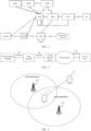
- Network system architecture in the embodiments of the present application, the network system architecture is shown in FIG. 1 , and the network system architecture includes a terminal, an access network, a User Plane Function (UPF) network element, an external data network, an Access Management Function (AMF) network element, a Session Management Function (SMF) network element, a Policy Control function (PCF) network element, an Application Function (AF) network element, a Network SliceSelection Function (NSSF) network element, an Authentication Server Function (AUSF) network element, and a Unified Data Management (UDM) network element.
- the terminal is connected with the access network at the access layer through Uu (a communication interface) interface, and then exchanges the access layer messages and performs the wireless data transmission.
- Uu a communication interface
- the terminal is connected with the AMF network element at the access layer through N1 (a communication interface) interface, and then exchanges the Non-access stratum (None Access Stratum) messages.
- the AMF network element has the mobility management function in the core network
- the SMF has the session management function in the core network.
- the AMF network element is also responsible for forwarding the session management message between the terminal and the SMF network element, and the AMF network element exchanges data with the SMF network element through the N11 (a communication interface) interface.
- the PCF network element has a policy management function in the core network, is responsible for formulating policies related to the mobility management, session management, and charging of the terminal, and exchanges data with the SMF network element through the N7 (a communication interface) interface. In addition, the PCF network element exchanges data with the AMF through the N15 (a communication interface) interface.
- the UPF network element has the user plane function in the core network, performs data transmission with the external data network through the N6 (a communication interface) interface, and performs data transmission with the access network through the N3 (a communication interface) interface. After the terminal accesses the mobile communication network through the Uu port, a PDU session is established for data transmission under the control of the SMF network element.
- the NSSF network element exchanges data with the AMF network element through the N22 (a communication interface) interface.
- the AUSF network element exchanges data with the AMF network element through the N12 (a communication interface) interface, and exchanges data with the UDM network element through the N13 (a communication interface) interface.
- the UDM network element performs data interaction with the AMF network element through the N8 (a communication interface) interface, and performs data interaction with the SMF network element through the N10 (a communication interface) interface.
- connection management states between the terminal that has been registered to the network and the AMF there are two connection management states between the terminal that has been registered to the network and the AMF: idle state or connected state. If the connection between the terminal and the access network device is established, the access network device establishes a connection with the AMF, so that the terminal can exchange NAS messages with the AMF. At this time, the terminal is in the CM-connected state, and the AMF also marks the state of the terminal as CM-connected state. If the connection between the terminal and the access network device is released, the terminal enters the CM-idle state, the connection between the access network device and the AMF is also released, and the AMF also marks the state of the terminal as the CM-idle state.
- connection between the terminal and the access network device is suspended, and the terminal is in the inactive state of the wireless connection in the CM-connected state
- the connection between the access network device and the AMF continues to be maintained, and the AMF still marks the UE state as the CM-connected state.
- the relay terminal and the communication terminal are terminals with Proximity Services (Prose) capability, and the relay terminal and the communication terminal can establish a connection and communicate through the PC5 interface.
- the relay terminal can not only connect to the access network device through the mobile communication network, but also can be used as a relay terminal.
- the relay terminal After the communication terminal establishes a connection with the relay terminal through the PC5 interface, the relay terminal establishes a connection with the access network device through the Uu interface, and then the communication terminal is connected with the access network device by using the relay terminal as the medium, and then conducts data interaction with the core network to which the communication terminal belongs.
- the communication terminal exchanges messages with the access layer through NG (a communication interface) interface.
- FIG. 3 shows a block diagram of a communication system provided by an exemplary embodiment of the present application.
- the communication system may include: an access network 12, a relay terminal 13 and a communication terminal 14.
- the access network 12 includes several network devices 120.
- the network device 120 may be a base station, which is an apparatus deployed in an access network to provide a wireless communication function for a terminal.
- the base station may include various forms of macro base station, micro base station, relay station, access point and so on.
- the names of devices with base station functions may be different.
- eNodeBs or eNBs In LTE systems, they are called eNodeBs or eNBs; in 5G NR-U systems, they are called gNodeBs or gNBs.
- the description of "base station” may change.
- the above-mentioned apparatuses for providing wireless communication functions for the relay terminal 13 are collectively referred to as the access network device.
- the relay terminal 13 and the communication terminal 14 may include various handheld devices, vehicle-mounted devices, wearable devices, computing devices or other processing devices connected to wireless modems with wireless communication capabilities, as well as various forms of user equipment, Mobile Station (MS), terminal (terminal device) and so on.
- MS Mobile Station
- terminal terminal device
- the access network device 120 and the relay terminal 13 communicate with each other through a certain air interface technology, such as a Uu interface, and the relay terminal 13 and the communication terminal 14 are connected through short-range communication.
- D2D Device to Device
- M2M Machine to Machine
- MTC Machine Type Communication
- V2V Vehicle to Vehicle
- V2X Vehicle to Everything
- FIG. 4 shows a flowchart of a communication method provided by an exemplary embodiment of the present application, which is applied to the communication terminal, the relay terminal, and the access network device described in FIG. 1 , and the method includes at least part of the following contents.
- the communication terminal establishes a connection with the relay terminal.
- both the communication terminal and the relay terminal have short-range communication capabilities. If the communication terminal and the relay terminal are located within the short-range communication range, the communication terminal and the relay terminal establish a short-range communication connection.
- the relay terminal has a short-range communication capability, and continuously sends a broadcast message, where the broadcast message is used to indicate that the relay terminal can provide a relay service for connection of other terminals. If the communication terminal needs to perform data transmission, and the communication terminal cannot currently connect to the access network device, and it scans and obtains the broadcast message sent by the relay terminal, then the communication terminal sends a connection request message to the relay terminal, and the relay terminal establishes a short-range communication connection with the communication terminal based on the connection request message.
- the communication terminal establishes a short-range communication connection with the relay terminal through a PC5 (a communication interface) interface.
- PC5 a communication interface
- the relay terminal establishes a connection with the access network device, and establishes a connection with the core network to which the relay terminal belongs through the connection with the access network device.
- the communication terminal can trigger the establishment of a connection between the relay terminal and the access network device, and then establish a connection with the core network to which the relay terminal belongs based on the connection with the access network device.
- the relay terminal is located in the broadcast range of the access network device, and the relay terminal has established a short-range communication connection with the communication terminal, then the relay terminal sends a connection establishment request to the access network device, and then the access network device establishes a connection with the relay terminal based on the connection establishment request. Moreover, after the relay terminal establishes the connection with the access network device, the relay terminal can also establish a connection with the core network to which the relay terminal belongs through the connection with the access network device.
- the core network is an AMF network element, or other network elements, which are not limited in the embodiments of the present application.
- the relay terminal After the relay terminal establishes a connection with the core network to which the relay terminal belongs, the relay terminal enters the CM-connected state.
- the relay terminal performs NAS message interaction with the core network to which the relay terminal belongs through the connected access network device.
- the communication terminal establishes a connection with the access network device through the relay terminal.
- the relay terminal can perform the forwarding service, and the communication terminal establishes a connection with the access network device through the short-range communication with the relay terminal.
- the relay device is a forwarding device. After receiving the communication message sent by the communication terminal, the relay terminal directly sends the communication message to the connected access network device.
- the relay terminal is a device used for transparent transmission, and the connection between the communication terminal and the access network device is realized by using the relay terminal as a medium.
- the communication terminal after the communication terminal is connected to the access network device through the relay terminal, the communication terminal can establish a connection with the core network to which the communication terminal belongs based on the connection with the access network device, and then the communication device can perform NAS message interaction with the core network to which the communication terminal.
- the core network to which the communication terminal belongs is an AMF network element, or other network elements, which are not limited in the embodiments of the present application.
- the relay terminal After the relay terminal establishes a connection with the core network to which the relay terminal belongs, the relay terminal enters the CM-connected state.
- the relay terminal is used as a medium, so that the communication terminal is connected to the access network device via the relay terminal, and then the communication terminal performs NAS message exchange with the core network to which the communication terminal belongs based on the connection with the access network device.
- the relay terminal expands the coverage of the access network device, and improves the efficiency of connecting the communication terminal and the access network device to realize communication.
- FIG. 4 shows a process in which a communication terminal establishes a connection with a core network to which the communication terminal belongs through a relay terminal, thereby implementing communication.
- the communication terminal may leave the connection state with the access network device, and the access network device may control the state of the relay terminal based on the state of the communication terminal.
- FIG. 5 may be referred to.
- the embodiment in FIG. 4 and the embodiment in FIG. 5 in the present application may be independent embodiments from each other, or the embodiment in FIG. 4 and the embodiment in FIG. 5 may be combined.
- FIG. 5 shows a flowchart of a state transition method provided by an exemplary embodiment of the present application, which is applied to the communication terminal, the relay terminal, and the access network device as shown in FIG. 1 , where the relay terminal is connected to the access network device, the relay terminal is connected with at least one communication terminal, and the communication terminal is connected with the access network device through the relay terminal, and the method includes at least part of the following contents.
- the access network device controls at least one communication terminal to leave a connection state with the access network device.
- the communication terminal is currently in a connection state with the access network device, and the connection state is a CM-connected state.
- the communication terminal leaving the connection state with the access network device includes two cases.
- the first case is that the communication terminal releases the wireless connection with the access network device and transitions to the CM-idle state.
- the second case is that the communication terminal suspends the wireless connection with the access network device, and switches to the inactive state of the radio resource control.
- the access network device sends a second wireless connection releasing message to at least one communication terminal.
- the second wireless connection releasing message is used for instructing the communication terminal to transition to the CM-idle state.
- the access network device Since the access network device needs to control at least one connected communication terminal to leave the connection state with the access network device, the access network device sends a second wireless connection releasing message to the at least one communication terminal, and after the communication terminal receives the second wireless connection releasing message sent by the access network device, it transitions to the CM-idle state based on the second wireless connection releasing message, and at this time, the communication terminal no longer communicates with the access network device.
- a second wireless connection suspension message is sent to at least one communication terminal.
- the second wireless connection suspension message is used for instructing the communication terminal to switch to the radio resource control inactive state.
- the access network device needs to control at least one connected communication terminal to leave the connection state with the access network device, the access network device sends a second wireless connection suspension message to the at least one communication terminal, and after receiving the second wireless connection suspension message sent by the access network device, the communication terminal is switched to the radio resource control inactive state based on the second wireless connection releasing message, and at this time, the communication terminal no longer communicates with the access network device.
- the embodiments of the present application are described by taking the relay terminal and the access network device in a connected state as an example.
- the relay terminal needs to connect with the access network device first, the relay terminal determines that it needs to establish a connection with the access network device through the wireless connection with the communication terminal, and sends the connection establishment request to the access network device, the access network device accesses the connection establishment request sent by the relay terminal through the connection with the communication terminal, and then establishes a wireless connection with the relay terminal.
- the first control message is used for instructing the relay terminal to leave the connection state with the access network device.
- the access network device since the access network device controls at least one communication terminal connected to the access network device to leave the connection state with the access network device, and the access network device also records the communication terminal connected to the network access device through the relay terminal, if for one relay terminal, all communication terminals connected with the access network device leave the connection state with the access network device through the relay terminal, it means that the relay terminal does not need to maintain the connection state with the access network device, then the access network device sends a first control message to the relay terminal to control the relay terminal to leave the connection state with the access network device.
- the relay terminal receives the first control message sent by the access network device.
- the relay terminal leaves the connection state with the access network device.
- the relay terminal After receiving the first control message sent by the access network device, the relay terminal determines that all communication terminals connected to the access network device through the relay terminal have left the connection state with the access network device. Thus, the terminal leaves the connection state with the access network device based on the received first control message.
- the relay terminal leaving the connection state with the access network device includes two situations.
- the first situation is that the relay terminal enters the CM-idle state and/or the Radio Resource Control (RRC)-idle state.
- RRC Radio Resource Control
- the first control message sent by the access network device to the relay terminal is the first wireless connection releasing message, and the relay terminal will enter the CM-idle state and/or the RRC-idle state after receiving the first wireless connection releasing message.
- the relay terminal may perform a state transition operation based on the first wireless connection releasing message, and the state transition operation performed includes three cases:
- the relay terminal After the relay terminal receives the first wireless connection releasing message, the relay terminal enters the CM-idle state and the RRC-idle state at the same time. Or, after the relay terminal receives the first wireless connection releasing message, the relay terminal first enters the RRC-idle state, and then transitions to the CM-idle state based on the RRC-idle state.
- the access network device not only sends the first wireless connection releasing message to the relay terminal, but also sends a context release message to the core network to which the relay terminal is connected.
- the context release message is used for instructing the core network to which the relay terminal is connected to release the context information of the relay terminal.
- the context information of the relay terminal is used for data exchange between the relay terminal and the core network to which the relay terminal is connected.
- the access network device Since the access network device controls the relay terminal to release the wireless connection of the relay terminal, and controls the relay terminal to enter the CM-idle state and/or the RRC-idle state, at this time, the relay terminal does not need to communicate with the core network to which the relay terminal belongs. At this time, the access network device sends a context release message to the core network connected to the relay terminal, and the core network connected to the relay terminal releases the context information of the relay terminal based on the context release message.
- the access network device when the access network device sends a second wireless connection releasing message to at least one communication terminal, or when the access network device sends a second wireless connection suspension message to at least one communication terminal, the access network device performs the step of sending the first wireless connection releasing message to the relay terminal.
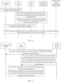
- FIG. 6 shows a flowchart of a state transition method provided by an exemplary embodiment of the present application.
- a communication terminal establishes a short-range communication connection with a relay terminal, and the relay terminal establishes a connection with the core network to which the relay terminal belongs through the connected access network device, and then performs NAS message interaction with the core network to which the relay terminal belongs.
- the communication terminal establishes a connection with the access network device through the relay terminal, and then establishes a connection with the core network to which the communication terminal belongs, and performs NAS message interaction with the core network to which the communication terminal belongs.
- the access network device sends a wireless connection releasing message to the communication terminal.
- the access network device sends a wireless connection releasing message or a wireless connection suspension message to the relay terminal.
- the second situation is that the relay terminal enters a radio resource control inactive state.
- the first control message sent by the access network device to the relay terminal is the first wireless connection suspension message, and the relay terminal will enter the radio resource control inactive state after receiving the first wireless connection suspension message. In addition, the relay terminal transitions to the radio resource control inactive state of the CM-connected state at this time.
- the access network device when the access network device sends the second wireless connection suspension message to at least one communication terminal, the access network device performs the step of sending the first wireless connection suspension message to the relay terminal.
- the access network device in the case that the access network device sends the second wireless connection suspension message to some of a plurality of communication terminals, and sends the second wireless connection releasing message to other communication terminals among the plurality of communication terminals, the access network device performs the step of sending the first wireless connection suspension message to the relay terminal.
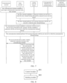
- FIG. 7 shows a flowchart of a state transition method provided by an exemplary embodiment of the present application.
- a communication terminal establishes a short-range communication connection with a relay terminal, and the relay terminal establishes a connection with the core network to which the relay terminal belongs through the connected access network device, and then performs NAS message interaction with the core network to which the relay terminal belongs.
- the communication terminal establishes a connection with the access network device through the relay terminal, and then establishes a connection with the core network to which the communication terminal belongs, and performs NAS message interaction with the core network to which the communication terminal belongs.
- the access network device sends a wireless connection suspension message to the communication terminal, and when it is determined that all communication terminals connected to the access network device through the relay terminal have left the connection state with the access network device, the access network device sends the wireless connection suspension message to the relay terminal.
- FIG. 6 and the embodiment in FIG. 7 are only exemplary descriptions of the present application, and the processes of establishing a connection between the communication terminal and the access network device through the relay terminal in FIG. 6 and FIG. 7 are only exemplary descriptions, not limiting that steps 501-504 in the present application must be performed on the basis of the process of establishing a connection between the communication terminal and the access network device through the relay terminal.
- the access network device determines that all communication terminals connected to the access network device through the relay terminal leave the connection state with the access network device as an example.
- the access network device not only determines that all communication terminals connected to the access network device through the relay terminal leave the connection state with the access network device, but also determines that there is no service transmission of the relay terminal itself with the connected core network, and then the access network device sends the first control information to the relay terminal, so that the relay terminal leaves the connection state with the access network device, which improves the accuracy of the relay terminal leaving the connection state with the access network device.
- the embodiments of the present application only take the relay terminal leaving the connection state with the access network device as an example for description.
- the relay terminal switches to the CM-connected state, and at this time, it can continue to perform data transmission with the core network to which the relay terminal belongs.
- the access network device determines that all communication terminals connected to the access network device through the relay terminal have left the connection state with the access network device, it means that the relay terminal does not need to be in the connection state with the access network device any longer, the access network device controls the relay terminal to leave the connection state with the access network device, so as to prevent the situation that the relay terminal is still in the connection state with the access network device to continue to consume resources, thereby saving the resource consumption of the relay terminal, and improving the communication quality of the relay terminal.
- FIG. 8 shows a block diagram of a state transition apparatus provided by an exemplary embodiment of the present application, which is applied to an access network device, where a relay terminal is connected to the access network device, the relay terminal is connected to at least one communication terminal, and the communication terminal is connected to the access network device through the relay terminal, and the apparatus includes:
- the relay terminal leaving the connection state with the access network device includes the relay terminal entering the connection management idle (CM-idle) state and/or the radio resource control idle (RRC-idle) state, and the first control message is a first wireless connection releasing message, and the first wireless connection releasing message is used for instructing the relay terminal to transition to the CM-idle state and/or the RRC-idle state.
- CM-idle connection management idle
- RRC-idle radio resource control idle
- the sending module 802 is further configured to send a context release message to the core network connected to the relay terminal, where the context release message is used for instructing the core network connected to the relay terminal to release the context information of the relay terminal.
- the relay terminal leaving the connection state with the access network device includes the relay terminal entering the radio resource control inactive state, the first control message is a first wireless connection suspension message, and the first wireless connection suspension message is used for instructing the relay terminal to switch to the RRC inactive state.
- control module 801 is configured to send a second wireless connection releasing message to at least one communication terminal, where the second wireless connection releasing message is used for instructing the communication terminal to transition to the CM-idle state.
- control module 801 is configured to send a second wireless connection suspension message to at least one communication terminal, where the second wireless connection suspension message is used for instructing the communication terminal to switch to a radio resource control inactive state.
- the apparatus further includes:
- FIG. 10 shows a block diagram of a state transition apparatus provided by an exemplary embodiment of the present application, which is applied to a relay terminal.
- the relay terminal is connected to an access network device, and the relay terminal is connected to at least one communication terminal, and the communication terminal is connected to the access network device through the relay terminal.
- the apparatus includes:
- leaving the connection state with the access network device includes entering the CM-idle state and/or the RRC-idle state, the first control message is a first wireless connection releasing message, and the first wireless connection releasing message is used for instructing the relay terminal to transition to the CM-idle state and/or the RRC-idle state.
- leaving the connection state with the access network device includes entering the radio resource control inactive state, the first control message is a first wireless connection suspension message, and the first wireless connection suspension message is used for instructing the relay terminal to transition to the radio resource control inactive state.
- the apparatus further includes:
- FIG. 12 shows a schematic structural diagram of a communication device provided by an exemplary embodiment of the present application.
- the communication device includes: a processor 1201, a receiver 1202, a transmitter 1203, a memory 1204, and a bus 1205.
- the processor 1201 includes one or more processing cores, and the processor 1201 executes various functional applications and information processing by running software programs and modules.
- the memory 1204 is connected to the processor 1201 through the bus 1205.
- the memory 1204 may be configured to store at least one instruction, and the processor 1201 may be configured to execute the at least one instruction to implement various steps in the above method embodiments.
- the communication device is an access network device or a relay terminal.
- the memory 1204 may be implemented by any type or combination of volatile or non-volatile storage devices including, but not limited to, a magnetic or optical disk, an electrically erasable and programmable Read Only Memory (EEPROM), an Erasable Programmable Read Only Memory (EPROM), a Static Random Access Memory (SRAM), a Read Only Memory (ROM), a Magnetic Memory, a Flash Memory, a Programmable Read Only Memory (PROM).
- EEPROM electrically erasable and programmable Read Only Memory
- EPROM Erasable Programmable Read Only Memory
- SRAM Static Random Access Memory
- ROM Read Only Memory
- Magnetic Memory Magnetic Memory
- Flash Memory a Programmable Read Only Memory
- a computer-readable storage medium in which an executable program code is stored, and the executable program code is loaded and executed by the processor to implement the above state transition methods performed by the communication device provided by the above-mentioned method embodiments.
- a chip is also provided, the chip includes programmable logic circuits and/or program instructions, and when the chip runs on an access network device or a relay terminal, it is configured to implement the above state transition methods.
- a computer program product is also provided, which is used to implement the above state transition methods when the computer program product is executed by a processor of an access network device or a relay terminal.
Landscapes
- Engineering & Computer Science (AREA)
- Computer Networks & Wireless Communication (AREA)
- Signal Processing (AREA)
- Mobile Radio Communication Systems (AREA)
Claims (12)
- Zustandswechselverfahren, angewandt auf ein Zugriffsnetzwerkgerät (120), wobei mit dem Zugriffsnetzwerkgerät (120) ein Relaisendgerät (13) verbunden ist, wobei das Relaisendgerät (13) mit mindestens einem Kommunikationsendgerät (14) verbunden ist und das mindestens eine Kommunikationsendgerät (14) über das Relaisendgerät (13) mit dem Zugriffsnetzwerkgerät (120) verbunden ist, wobei das Verfahren Folgendes umfasst:Steuern (501) des mindestens einen Kommunikationsendgeräts (14), einen Zustand CM-connected, verbindungsmanagement-verbunden, mit dem Zugriffsnetzwerkgerät (120) zu verlassen,Bestimmen, dass jedes des mindestens einen Kommunikationsendgeräts (14), das über das Relaisendgerät (13) mit dem Zugriffsnetzwerkgerät (120) verbunden ist, den Zustand CM-connected mit dem Zugriffsnetzwerkgerät (120) verlassen hat, und Senden (502) einer ersten Steuernachricht an das Relaisendgerät (13), wobei die erste Steuernachricht verwendet wird, um das Relaisendgerät (13) anzuweisen, einen Zustand CM-connected mit dem Zugriffsnetzwerkgerät (120) zu verlassen,wobei das Steuern (501) des mindestens einen Kommunikationsendgeräts (14), den Zustand CM-connected mit dem Zugriffsnetzwerkgerät (120) zu verlassen, eines des Folgenden umfasst:Senden einer Nachricht zur Freigabe einer drahtlosen Verbindung an das mindestens eine Kommunikationsendgerät (14), wobei die Nachricht zur Freigabe einer drahtlosen Verbindung verwendet wird, um das mindestens eine Kommunikationsendgerät (14) anzuweisen, in einen Zustand CM-idle, Verbindungsmanagement-Leerlauf, zu wechseln, undSenden einer zweiten Nachricht zum Aussetzen der drahtlosen Verbindung an das mindestens eine Kommunikationsendgerät (14), wobei die zweite Nachricht zum Aussetzen der drahtlosen Verbindung verwendet wird, um das mindestens eine Kommunikationsendgerät (14) anzuweisen, in einen Zustand inaktiver Funkressourcensteuerung zu wechseln.
- Verfahren nach Anspruch 1, wobei das Verlassen des Zustandes CM-connected mit dem Zugriffsnetzwerkgerät (120) durch das Relaisendgerät (13) Folgendes umfasst: Eintreten des Relaisendgeräts (13) in den Zustand CM-idle und/oder einen Zustand RRC-idle, Funkressourcensteuerungs-Leerlauf, wobei die erste Steuernachricht eine erste Nachricht zur Freigabe einer drahtlosen Verbindung ist und die erste Nachricht zur Freigabe einer drahtlosen Verbindung verwendet wird, um das Relaisendgerät (13) anzuweisen, in den Zustand CM-idle und/oder den Zustand RRC-idle zu wechseln.
- Verfahren nach Anspruch 2, wobei das Verfahren ferner Folgendes umfasst:
Senden einer Nachricht zur Freigabe von Kontext an ein Kernnetzwerk, mit dem das Relaisendgerät (13) verbunden ist, wobei die Nachricht zur Freigabe von Kontext verwendet wird, um das Kernnetzwerk, mit dem das Relaisendgerät (13) verbunden ist, anzuweisen, Kontextinformationen des Relaisendgeräts (13) freizugeben. - Verfahren nach Anspruch 1, wobei das Verlassen des Zustandes CM-connected mit dem Zugriffsnetzwerkgerät (120) durch das Relaisendgerät (13) Folgendes umfasst: Eintreten des Relaisendgeräts (13) in einen Zustand inaktiver Funkressourcensteuerung, wobei die erste Steuernachricht eine erste Nachricht zum Aussetzen der drahtlosen Verbindung ist und die erste Nachricht zum Aussetzen der drahtlosen Verbindung verwendet wird, um das Relaisendgerät (13) anzuweisen, in den Zustand inaktiver Funkressourcensteuerung zu wechseln.
- Verfahren nach Anspruch 1, wobei das Verfahren ferner Folgendes umfasst:Empfangen einer Anfrage zum Einrichten einer Verbindung, die durch das Relaisendgerät gesendet wird,Einrichten einer drahtlosen Verbindung mit dem Relaisendgerät.
- Zustandswechselverfahren, angewandt auf ein Relaisendgerät (13), wobei das Relaisendgerät (13) mit einem Zugriffsnetzwerkgerät (120) verbunden ist, wobei das Relaisendgerät (13) mit mindestens einem Kommunikationsendgerät (14) verbunden ist und das Kommunikationsendgerät (14) über das Relaisendgerät mit dem Zugriffsnetzwerkgerät (120) verbunden ist, wobei das Verfahren Folgendes umfasst:Empfangen (503) einer ersten Steuernachricht, die von dem Zugriffsnetzwerkgerät (120) gesendet wird, wobei die erste Steuernachricht von dem Zugriffsnetzwerkgerät (120) nach dem Bestimmen gesendet wird, dass jedes des mindestens einen Kommunikationsendgeräts (14), das über das Relaisendgerät (13) mit dem Zugriffsnetzwerkgerät (120) verbunden ist, einen Zustand CM-connected, verbindungsmanagement-verbunden, mit dem Zugriffsnetzwerkgerät (120) verlassen hat, wobei das Zugriffsnetzwerkgerät (120) durch eines des Folgenden das mindestens eine Kommunikationsendgerät (14) steuert, den Zustand CM-connected mit dem Zugriffsnetzwerkgerät (120) zu verlassen: Senden einer Nachricht zur Freigabe aus einer drahtlosen Verbindung an das mindestens eine Kommunikationsendgerät (14), um das mindestens eine Kommunikationsendgerät (14) anzuweisen, in einen Zustand CM-idle, Verbindungsmanagement-Leerlauf, zu wechseln, und Senden einer zweiten Nachricht zum Aussetzen einer drahtlosen Verbindung an das mindestens eine Kommunikationsendgerät (14), um das mindestens eine Kommunikationsendgerät (14) anzuweisen, in einen Zustand inaktiver Funkressourcensteuerung zu wechseln,Verlassen (504) eines Zustandes CM-connected mit dem Zugriffsnetzwerkgerät (120), basierend auf der ersten Steuernachricht.
- Verfahren nach Anspruch 6, wobei das Verlassen (504) des Zustandes CM-connected mit dem Zugriffsnetzwerkgerät Folgendes umfasst: Eintreten in den Zustand CM-idle und/oder einen Zustand RRC-idle, Funkressourcensteuerungs-Leerlauf, wobei die erste Steuernachricht eine erste Nachricht zur Freigabe einer drahtlosen Verbindung ist und die erste Nachricht zur Freigabe einer drahtlosen Verbindung verwendet wird, um das Relaisendgerät (13) anzuweisen, in den Zustand CM-idle und/oder den Zustand RRC-idle zu wechseln.
- Verfahren nach Anspruch 6, wobei das Verlassen (504) des Zustandes CM-connected mit dem Zugriffsnetzwerkgerät (120) Folgendes umfasst: Eintreten in den Zustand inaktiver Funkressourcensteuerung, wobei die erste Steuernachricht eine erste Nachricht zum Aussetzen der drahtlosen Verbindung ist und die erste Nachricht zum Aussetzen der drahtlosen Verbindung verwendet wird, um das Relaisendgerät (13) anzuweisen, in den Zustand inaktiver Funkressourcensteuerung zu wechseln.
- Verfahren nach Anspruch 6, wobei das Verfahren ferner Folgendes umfasst:Senden einer Anfrage zum Einrichten einer Verbindung an das Zugriffsnetzwerkgerät über eine drahtlose Verbindung mit dem mindestens einen Kommunikationsendgerät,Einrichten einer drahtlosen Verbindung mit dem Zugriffsnetzwerkgerät.
- Zugriffsnetzwerkgerät (120), Folgendes umfassend:einen Prozessor,einen Sendeempfänger, der mit dem Prozessor verbunden ist,einen Speicher zum Speichern eines ausführbaren Programmcodes des Prozessors,wobei der Prozessor dafür konfiguriert ist, den ausführbaren Programmcode zu laden und auszuführen, um das Zustandswechselverfahren nach einem der Ansprüche 1 bis 5 zu implementieren.
- Relaisendgerät (13), umfassend:einen Prozessor,einen Sendeempfänger, der mit dem Prozessor verbunden ist,einen Speicher zum Speichern eines ausführbaren Programmcodes des Prozessors,wobei der Prozessor dafür konfiguriert ist, den ausführbaren Programmcode zu laden und auszuführen, um das Zustandswechselverfahren nach einem der Ansprüche 6 bis 9 zu implementieren.
- Computerlesbares Speichermedium, wobei in dem lesbaren Speichermedium ein ausführbarer Programmcode gespeichert ist und der ausführbare Programmcode von einem Prozessor geladen und ausgeführt wird, um das Zustandswechselverfahren nach einem der Ansprüche 1 bis 9 zu implementieren.
Applications Claiming Priority (1)
| Application Number | Priority Date | Filing Date | Title |
|---|---|---|---|
| PCT/CN2021/075519 WO2022165752A1 (zh) | 2021-02-05 | 2021-02-05 | 状态转换方法、装置、设备及存储介质 |
Publications (3)
| Publication Number | Publication Date |
|---|---|
| EP4243509A1 EP4243509A1 (de) | 2023-09-13 |
| EP4243509A4 EP4243509A4 (de) | 2024-01-17 |
| EP4243509B1 true EP4243509B1 (de) | 2025-04-30 |
Family
ID=82740791
Family Applications (1)
| Application Number | Title | Priority Date | Filing Date |
|---|---|---|---|
| EP21923769.0A Active EP4243509B1 (de) | 2021-02-05 | 2021-02-05 | Zustandsumschaltverfahren, vorrichtung, vorrichtung und speichermedium |
Country Status (6)
| Country | Link |
|---|---|
| US (1) | US11997743B2 (de) |
| EP (1) | EP4243509B1 (de) |
| JP (1) | JP7749018B2 (de) |
| KR (1) | KR20230140558A (de) |
| CN (2) | CN117222054A (de) |
| WO (1) | WO2022165752A1 (de) |
Families Citing this family (1)
| Publication number | Priority date | Publication date | Assignee | Title |
|---|---|---|---|---|
| KR20240124556A (ko) * | 2023-02-09 | 2024-08-19 | 삼성전자주식회사 | 차세대 이동통신 시스템에서 네트워크 제어 리피터의 idle / inactive 동작 시 셀 미정합을 해결하는 방법 및 장치 |
Family Cites Families (30)
| Publication number | Priority date | Publication date | Assignee | Title |
|---|---|---|---|---|
| JP5277210B2 (ja) * | 2010-06-24 | 2013-08-28 | 株式会社エヌ・ティ・ティ・ドコモ | 移動通信方法及びリレーノード |
| CN102378329B (zh) * | 2010-08-16 | 2014-08-20 | 华为技术有限公司 | 实现非连续接收的方法和装置 |
| US9363753B2 (en) * | 2011-07-19 | 2016-06-07 | Qualcomm Incorporated | Sleep mode for user equipment relays |
| KR102039908B1 (ko) * | 2013-04-01 | 2019-11-04 | 삼성전자주식회사 | 단말간 통신을 위한 상태 천이 방법 및 장치 |
| KR20170129917A (ko) * | 2015-04-03 | 2017-11-27 | 후아웨이 테크놀러지 컴퍼니 리미티드 | 데이터 송신 방법, 사용자 장비, 및 기지국 |
| CN106211024A (zh) * | 2015-04-10 | 2016-12-07 | 中兴通讯股份有限公司 | 信息处理方法及通信节点 |
| KR101724232B1 (ko) * | 2015-05-26 | 2017-04-06 | 엘지전자 주식회사 | 무선 통신 시스템에서 단말에 의해 수행되는 링크 해제 방법 및 상기 방법을 이용하는 단말 |
| EP3329732A4 (de) * | 2015-07-29 | 2019-05-08 | Sharp Kabushiki Kaisha | Verfahren für relaisprozedur von vorrichtung zu vorrichtung |
| WO2017030175A1 (ja) * | 2015-08-18 | 2017-02-23 | 株式会社テイエルブイ | 通信端末及び無線通信システム |
| EP3343994B1 (de) * | 2015-09-25 | 2020-08-12 | Huawei Technologies Co., Ltd. | Dienstverarbeitungsverfahren und -vorrichtung |
| CN106954282A (zh) * | 2016-01-06 | 2017-07-14 | 夏普株式会社 | Ue上下文管理方法和设备 |
| CN106341877A (zh) * | 2016-09-29 | 2017-01-18 | 青岛海信移动通信技术股份有限公司 | 中继设备的状态控制方法、中继设备及通信系统 |
| CN109863783B (zh) * | 2017-04-28 | 2022-05-31 | Lg 电子株式会社 | 根据edt发送数据的方法 |
| US11419025B2 (en) * | 2017-08-11 | 2022-08-16 | Huawei Technologies Co., Ltd. | Path switching method, apparatus and system |
| CN109474937A (zh) * | 2017-09-08 | 2019-03-15 | 索尼公司 | 无线通信方法和无线通信设备 |
| CN108541032B (zh) * | 2017-09-22 | 2022-04-29 | 中兴通讯股份有限公司 | 无线基站分离架构下的通信方法、功能实体及无线基站 |
| CN109729524B (zh) * | 2017-10-31 | 2021-11-19 | 华为技术有限公司 | 一种rrc连接恢复方法及装置 |
| CN109951890B (zh) * | 2017-12-21 | 2022-03-22 | 中国科学院深圳先进技术研究院 | 一种数据通信方法、中继节点、终端节点及通信系统 |
| CN110876175B (zh) * | 2018-08-31 | 2021-07-16 | 大唐移动通信设备有限公司 | 链路中断的处理方法、中继节点及计算机可读存储介质 |
| WO2020144010A1 (en) * | 2019-01-10 | 2020-07-16 | Signify Holding B.V. | Signal-repeater device operable in low-power repeater-operation mode |
| WO2021102782A1 (en) * | 2019-11-28 | 2021-06-03 | Apple Inc. | Access control at a relay user equipment |
| WO2021133047A1 (ko) * | 2019-12-27 | 2021-07-01 | 엘지전자 주식회사 | 릴레이 통신 ue가 설정 업데이트 시에 원격 ue를 효율적으로 지원하는 방법 |
| WO2021134162A1 (en) * | 2019-12-30 | 2021-07-08 | Mediatek Singapore Pte. Ltd. | Methods and apparatus of system information delivery for sidelink relay |
| CN115553051A (zh) * | 2020-03-06 | 2022-12-30 | 弗劳恩霍夫应用研究促进协会 | 核心网络处的远程ue控制信息建立 |
| US12349104B2 (en) * | 2020-04-03 | 2025-07-01 | Beijing Xiaomi Mobile Software Co., Ltd. | Paging processing method and apparatus, user equipment, base station, and storage medium |
| CN113938903B (zh) * | 2020-06-29 | 2025-03-11 | 华为技术有限公司 | 一种通信方法及相关设备 |
| CN114079934B (zh) * | 2020-08-12 | 2025-05-30 | 华为技术有限公司 | 一种中继通信方法及通信装置 |
| KR20220071107A (ko) * | 2020-11-23 | 2022-05-31 | 아서스테크 컴퓨터 인코포레이션 | 무선 통신 시스템에서 ue-대-네트워크 릴레이를 통해 시스템 정보 및 페이징을 획득하기 위한 방법 및 장치 |
| CN114531717A (zh) * | 2020-11-23 | 2022-05-24 | 华硕电脑股份有限公司 | 获取系统信息和经由ue到网络的中继寻呼的方法和设备 |
| KR102673985B1 (ko) * | 2020-12-18 | 2024-06-12 | 아서스테크 컴퓨터 인코포레이션 | 무선 통신 시스템에서 ue 대 네트워크 릴레이 통신을 지원하기 위한 방법 및 장치 |
-
2021
- 2021-02-05 EP EP21923769.0A patent/EP4243509B1/de active Active
- 2021-02-05 CN CN202311333646.7A patent/CN117222054A/zh active Pending
- 2021-02-05 KR KR1020237021778A patent/KR20230140558A/ko active Pending
- 2021-02-05 CN CN202180075025.6A patent/CN116349402A/zh active Pending
- 2021-02-05 JP JP2023540609A patent/JP7749018B2/ja active Active
- 2021-02-05 WO PCT/CN2021/075519 patent/WO2022165752A1/zh not_active Ceased
-
2023
- 2023-06-06 US US18/206,199 patent/US11997743B2/en active Active
Also Published As
| Publication number | Publication date |
|---|---|
| WO2022165752A1 (zh) | 2022-08-11 |
| EP4243509A1 (de) | 2023-09-13 |
| JP7749018B2 (ja) | 2025-10-03 |
| US11997743B2 (en) | 2024-05-28 |
| JP2024510071A (ja) | 2024-03-06 |
| EP4243509A4 (de) | 2024-01-17 |
| CN117222054A (zh) | 2023-12-12 |
| KR20230140558A (ko) | 2023-10-06 |
| CN116349402A (zh) | 2023-06-27 |
| US20230319945A1 (en) | 2023-10-05 |
Similar Documents
| Publication | Publication Date | Title |
|---|---|---|
| US12075277B2 (en) | Method of processing network slice based congestion, device and system thereof | |
| US20220150994A1 (en) | Session Management Method and System, and Terminal for Locating a User Plane Function (UPF) Entity when a Session is an Inactive State | |
| US12231946B2 (en) | Communications method and apparatus | |
| JP2019537357A (ja) | ページング方法、基地局および端末 | |
| CN114071801B (zh) | 一种终端设备的状态指示方法及通信装置 | |
| US11997743B2 (en) | State switching method, apparatus, device, and storage medium | |
| JP7013474B2 (ja) | コンテキスト解放方法、機器及びシステム | |
| US20250227802A1 (en) | Communication method and apparatus | |
| CN105682079B (zh) | 用户识别卡控制方法及终端 | |
| EP4167681A1 (de) | Kommunikationsverfahren und -vorrichtung | |
| US20250365694A1 (en) | Method and apparatus for stopping positioning terminal, device and storage medium | |
| WO2023231032A1 (zh) | 非激活态组播业务区域的确定方法、配置方法、及装置 | |
| WO2023231033A1 (zh) | 指示信息发送方法、组播业务更新方法、装置及介质 | |
| US20250261155A1 (en) | Uplink positioning reference signal configuration method and apparatus, and device and storage medium | |
| WO2024011525A1 (zh) | 上行定位方法、装置及存储介质 | |
| WO2023230896A1 (zh) | 参数配置方法、装置、设备及存储介质 | |
| WO2024199148A1 (zh) | 一种通信方法及装置 | |
| WO2024067383A1 (zh) | 连接建立方法、终端及网络侧设备 | |
| WO2024217185A1 (zh) | 一种通信方法及装置 | |
| CN121604185A (zh) | 一种通信方法及装置 | |
| WO2026055991A1 (zh) | 无线通信的方法、终端设备、核心网设备和接入网设备 | |
| WO2023245412A1 (zh) | 上行定位参考信号的配置方法、装置、设备及存储介质 | |
| CN121510383A (zh) | 信息传输方法及通信装置 | |
| CN120475548A (zh) | 一种通信方法及装置 | |
| CN117956442A (zh) | 一种信息传输方法、装置、设备和存储介质 |
Legal Events
| Date | Code | Title | Description |
|---|---|---|---|
| STAA | Information on the status of an ep patent application or granted ep patent |
Free format text: STATUS: THE INTERNATIONAL PUBLICATION HAS BEEN MADE |
|
| PUAI | Public reference made under article 153(3) epc to a published international application that has entered the european phase |
Free format text: ORIGINAL CODE: 0009012 |
|
| STAA | Information on the status of an ep patent application or granted ep patent |
Free format text: STATUS: REQUEST FOR EXAMINATION WAS MADE |
|
| 17P | Request for examination filed |
Effective date: 20230607 |
|
| AK | Designated contracting states |
Kind code of ref document: A1 Designated state(s): AL AT BE BG CH CY CZ DE DK EE ES FI FR GB GR HR HU IE IS IT LI LT LU LV MC MK MT NL NO PL PT RO RS SE SI SK SM TR |
|
| A4 | Supplementary search report drawn up and despatched |
Effective date: 20231218 |
|
| RIC1 | Information provided on ipc code assigned before grant |
Ipc: H04W 76/27 20180101ALI20231212BHEP Ipc: H04B 7/14 20060101ALI20231212BHEP Ipc: H04W 76/30 20180101ALI20231212BHEP Ipc: H04W 88/04 20090101ALI20231212BHEP Ipc: H04W 52/02 20090101AFI20231212BHEP |
|
| DAV | Request for validation of the european patent (deleted) | ||
| DAX | Request for extension of the european patent (deleted) | ||
| STAA | Information on the status of an ep patent application or granted ep patent |
Free format text: STATUS: EXAMINATION IS IN PROGRESS |
|
| 17Q | First examination report despatched |
Effective date: 20240809 |
|
| GRAP | Despatch of communication of intention to grant a patent |
Free format text: ORIGINAL CODE: EPIDOSNIGR1 |
|
| STAA | Information on the status of an ep patent application or granted ep patent |
Free format text: STATUS: GRANT OF PATENT IS INTENDED |
|
| RIC1 | Information provided on ipc code assigned before grant |
Ipc: H04W 88/04 20090101ALN20250113BHEP Ipc: H04W 76/30 20180101ALN20250113BHEP Ipc: H04B 7/15 20060101ALN20250113BHEP Ipc: H04W 76/27 20180101ALI20250113BHEP Ipc: H04W 52/02 20090101AFI20250113BHEP |
|
| INTG | Intention to grant announced |
Effective date: 20250124 |
|
| GRAS | Grant fee paid |
Free format text: ORIGINAL CODE: EPIDOSNIGR3 |
|
| GRAA | (expected) grant |
Free format text: ORIGINAL CODE: 0009210 |
|
| STAA | Information on the status of an ep patent application or granted ep patent |
Free format text: STATUS: THE PATENT HAS BEEN GRANTED |
|
| AK | Designated contracting states |
Kind code of ref document: B1 Designated state(s): AL AT BE BG CH CY CZ DE DK EE ES FI FR GB GR HR HU IE IS IT LI LT LU LV MC MK MT NL NO PL PT RO RS SE SI SK SM TR |
|
| REG | Reference to a national code |
Ref country code: CH Ref legal event code: EP Ref country code: GB Ref legal event code: FG4D |
|
| REG | Reference to a national code |
Ref country code: IE Ref legal event code: FG4D |
|
| REG | Reference to a national code |
Ref country code: DE Ref legal event code: R096 Ref document number: 602021030187 Country of ref document: DE |
|
| REG | Reference to a national code |
Ref country code: NL Ref legal event code: MP Effective date: 20250430 |
|
| REG | Reference to a national code |
Ref country code: AT Ref legal event code: MK05 Ref document number: 1791270 Country of ref document: AT Kind code of ref document: T Effective date: 20250430 |
|
| P01 | Opt-out of the competence of the unified patent court (upc) registered |
Free format text: CASE NUMBER: UPC_APP_5258_4243509/2025 Effective date: 20250829 |
|
| PG25 | Lapsed in a contracting state [announced via postgrant information from national office to epo] |
Ref country code: FI Free format text: LAPSE BECAUSE OF FAILURE TO SUBMIT A TRANSLATION OF THE DESCRIPTION OR TO PAY THE FEE WITHIN THE PRESCRIBED TIME-LIMIT Effective date: 20250430 Ref country code: PT Free format text: LAPSE BECAUSE OF FAILURE TO SUBMIT A TRANSLATION OF THE DESCRIPTION OR TO PAY THE FEE WITHIN THE PRESCRIBED TIME-LIMIT Effective date: 20250901 Ref country code: ES Free format text: LAPSE BECAUSE OF FAILURE TO SUBMIT A TRANSLATION OF THE DESCRIPTION OR TO PAY THE FEE WITHIN THE PRESCRIBED TIME-LIMIT Effective date: 20250430 |
|
| REG | Reference to a national code |
Ref country code: LT Ref legal event code: MG9D |
|
| PG25 | Lapsed in a contracting state [announced via postgrant information from national office to epo] |
Ref country code: NO Free format text: LAPSE BECAUSE OF FAILURE TO SUBMIT A TRANSLATION OF THE DESCRIPTION OR TO PAY THE FEE WITHIN THE PRESCRIBED TIME-LIMIT Effective date: 20250730 Ref country code: GR Free format text: LAPSE BECAUSE OF FAILURE TO SUBMIT A TRANSLATION OF THE DESCRIPTION OR TO PAY THE FEE WITHIN THE PRESCRIBED TIME-LIMIT Effective date: 20250731 |
|
| PG25 | Lapsed in a contracting state [announced via postgrant information from national office to epo] |
Ref country code: NL Free format text: LAPSE BECAUSE OF FAILURE TO SUBMIT A TRANSLATION OF THE DESCRIPTION OR TO PAY THE FEE WITHIN THE PRESCRIBED TIME-LIMIT Effective date: 20250430 Ref country code: PL Free format text: LAPSE BECAUSE OF FAILURE TO SUBMIT A TRANSLATION OF THE DESCRIPTION OR TO PAY THE FEE WITHIN THE PRESCRIBED TIME-LIMIT Effective date: 20250430 |
|
| PG25 | Lapsed in a contracting state [announced via postgrant information from national office to epo] |
Ref country code: BG Free format text: LAPSE BECAUSE OF FAILURE TO SUBMIT A TRANSLATION OF THE DESCRIPTION OR TO PAY THE FEE WITHIN THE PRESCRIBED TIME-LIMIT Effective date: 20250430 |
|
| PG25 | Lapsed in a contracting state [announced via postgrant information from national office to epo] |
Ref country code: HR Free format text: LAPSE BECAUSE OF FAILURE TO SUBMIT A TRANSLATION OF THE DESCRIPTION OR TO PAY THE FEE WITHIN THE PRESCRIBED TIME-LIMIT Effective date: 20250430 |
|
| PG25 | Lapsed in a contracting state [announced via postgrant information from national office to epo] |
Ref country code: AT Free format text: LAPSE BECAUSE OF FAILURE TO SUBMIT A TRANSLATION OF THE DESCRIPTION OR TO PAY THE FEE WITHIN THE PRESCRIBED TIME-LIMIT Effective date: 20250430 |
|
| PG25 | Lapsed in a contracting state [announced via postgrant information from national office to epo] |
Ref country code: RS Free format text: LAPSE BECAUSE OF FAILURE TO SUBMIT A TRANSLATION OF THE DESCRIPTION OR TO PAY THE FEE WITHIN THE PRESCRIBED TIME-LIMIT Effective date: 20250731 |
|
| PG25 | Lapsed in a contracting state [announced via postgrant information from national office to epo] |
Ref country code: IS Free format text: LAPSE BECAUSE OF FAILURE TO SUBMIT A TRANSLATION OF THE DESCRIPTION OR TO PAY THE FEE WITHIN THE PRESCRIBED TIME-LIMIT Effective date: 20250830 |
|
| PG25 | Lapsed in a contracting state [announced via postgrant information from national office to epo] |
Ref country code: LV Free format text: LAPSE BECAUSE OF FAILURE TO SUBMIT A TRANSLATION OF THE DESCRIPTION OR TO PAY THE FEE WITHIN THE PRESCRIBED TIME-LIMIT Effective date: 20250430 |
|
| PGFP | Annual fee paid to national office [announced via postgrant information from national office to epo] |
Ref country code: GB Payment date: 20251218 Year of fee payment: 6 |
|
| PG25 | Lapsed in a contracting state [announced via postgrant information from national office to epo] |
Ref country code: DK Free format text: LAPSE BECAUSE OF FAILURE TO SUBMIT A TRANSLATION OF THE DESCRIPTION OR TO PAY THE FEE WITHIN THE PRESCRIBED TIME-LIMIT Effective date: 20250430 Ref country code: SM Free format text: LAPSE BECAUSE OF FAILURE TO SUBMIT A TRANSLATION OF THE DESCRIPTION OR TO PAY THE FEE WITHIN THE PRESCRIBED TIME-LIMIT Effective date: 20250430 |
|
| PGFP | Annual fee paid to national office [announced via postgrant information from national office to epo] |
Ref country code: FR Payment date: 20251222 Year of fee payment: 6 |
|
| PG25 | Lapsed in a contracting state [announced via postgrant information from national office to epo] |
Ref country code: CZ Free format text: LAPSE BECAUSE OF FAILURE TO SUBMIT A TRANSLATION OF THE DESCRIPTION OR TO PAY THE FEE WITHIN THE PRESCRIBED TIME-LIMIT Effective date: 20250430 |
|
| PG25 | Lapsed in a contracting state [announced via postgrant information from national office to epo] |
Ref country code: EE Free format text: LAPSE BECAUSE OF FAILURE TO SUBMIT A TRANSLATION OF THE DESCRIPTION OR TO PAY THE FEE WITHIN THE PRESCRIBED TIME-LIMIT Effective date: 20250430 |
|
| PG25 | Lapsed in a contracting state [announced via postgrant information from national office to epo] |
Ref country code: SK Free format text: LAPSE BECAUSE OF FAILURE TO SUBMIT A TRANSLATION OF THE DESCRIPTION OR TO PAY THE FEE WITHIN THE PRESCRIBED TIME-LIMIT Effective date: 20250430 |
|
| PG25 | Lapsed in a contracting state [announced via postgrant information from national office to epo] |
Ref country code: IT Free format text: LAPSE BECAUSE OF FAILURE TO SUBMIT A TRANSLATION OF THE DESCRIPTION OR TO PAY THE FEE WITHIN THE PRESCRIBED TIME-LIMIT Effective date: 20250430 |
|
| REG | Reference to a national code |
Ref country code: DE Ref legal event code: R097 Ref document number: 602021030187 Country of ref document: DE |
|
| PLBE | No opposition filed within time limit |
Free format text: ORIGINAL CODE: 0009261 |
|
| STAA | Information on the status of an ep patent application or granted ep patent |
Free format text: STATUS: NO OPPOSITION FILED WITHIN TIME LIMIT |
|
| REG | Reference to a national code |
Ref country code: CH Ref legal event code: L10 Free format text: ST27 STATUS EVENT CODE: U-0-0-L10-L00 (AS PROVIDED BY THE NATIONAL OFFICE) Effective date: 20260311 |