EP4243494B1 - Sensing method and terminal device - Google Patents
Sensing method and terminal device Download PDFInfo
- Publication number
- EP4243494B1 EP4243494B1 EP21888097.9A EP21888097A EP4243494B1 EP 4243494 B1 EP4243494 B1 EP 4243494B1 EP 21888097 A EP21888097 A EP 21888097A EP 4243494 B1 EP4243494 B1 EP 4243494B1
- Authority
- EP
- European Patent Office
- Prior art keywords
- terminal device
- sensing
- slots
- slot
- resource pool
- Prior art date
- Legal status (The legal status is an assumption and is not a legal conclusion. Google has not performed a legal analysis and makes no representation as to the accuracy of the status listed.)
- Active
Links
Images


Classifications
-
- H—ELECTRICITY
- H04—ELECTRIC COMMUNICATION TECHNIQUE
- H04W—WIRELESS COMMUNICATION NETWORKS
- H04W72/00—Local resource management
- H04W72/40—Resource management for direct mode communication, e.g. D2D or sidelink
-
- H—ELECTRICITY
- H04—ELECTRIC COMMUNICATION TECHNIQUE
- H04W—WIRELESS COMMUNICATION NETWORKS
- H04W24/00—Supervisory, monitoring or testing arrangements
- H04W24/02—Arrangements for optimising operational condition
-
- H—ELECTRICITY
- H04—ELECTRIC COMMUNICATION TECHNIQUE
- H04W—WIRELESS COMMUNICATION NETWORKS
- H04W28/00—Network traffic management; Network resource management
- H04W28/16—Central resource management; Negotiation of resources or communication parameters, e.g. negotiating bandwidth or QoS [Quality of Service]
- H04W28/26—Resource reservation
-
- H—ELECTRICITY
- H04—ELECTRIC COMMUNICATION TECHNIQUE
- H04W—WIRELESS COMMUNICATION NETWORKS
- H04W4/00—Services specially adapted for wireless communication networks; Facilities therefor
- H04W4/30—Services specially adapted for particular environments, situations or purposes
- H04W4/40—Services specially adapted for particular environments, situations or purposes for vehicles, e.g. vehicle-to-pedestrians [V2P]
- H04W4/44—Services specially adapted for particular environments, situations or purposes for vehicles, e.g. vehicle-to-pedestrians [V2P] for communication between vehicles and infrastructures, e.g. vehicle-to-cloud [V2C] or vehicle-to-home [V2H]
-
- H—ELECTRICITY
- H04—ELECTRIC COMMUNICATION TECHNIQUE
- H04W—WIRELESS COMMUNICATION NETWORKS
- H04W4/00—Services specially adapted for wireless communication networks; Facilities therefor
- H04W4/30—Services specially adapted for particular environments, situations or purposes
- H04W4/40—Services specially adapted for particular environments, situations or purposes for vehicles, e.g. vehicle-to-pedestrians [V2P]
- H04W4/46—Services specially adapted for particular environments, situations or purposes for vehicles, e.g. vehicle-to-pedestrians [V2P] for vehicle-to-vehicle communication [V2V]
-
- H—ELECTRICITY
- H04—ELECTRIC COMMUNICATION TECHNIQUE
- H04W—WIRELESS COMMUNICATION NETWORKS
- H04W72/00—Local resource management
- H04W72/02—Selection of wireless resources by user or terminal
-
- H—ELECTRICITY
- H04—ELECTRIC COMMUNICATION TECHNIQUE
- H04W—WIRELESS COMMUNICATION NETWORKS
- H04W72/00—Local resource management
- H04W72/04—Wireless resource allocation
- H04W72/044—Wireless resource allocation based on the type of the allocated resource
- H04W72/0446—Resources in time domain, e.g. slots or frames
-
- H—ELECTRICITY
- H04—ELECTRIC COMMUNICATION TECHNIQUE
- H04W—WIRELESS COMMUNICATION NETWORKS
- H04W72/00—Local resource management
- H04W72/20—Control channels or signalling for resource management
- H04W72/23—Control channels or signalling for resource management in the downlink direction of a wireless link, i.e. towards a terminal
-
- H—ELECTRICITY
- H04—ELECTRIC COMMUNICATION TECHNIQUE
- H04W—WIRELESS COMMUNICATION NETWORKS
- H04W72/00—Local resource management
- H04W72/50—Allocation or scheduling criteria for wireless resources
- H04W72/56—Allocation or scheduling criteria for wireless resources based on priority criteria
- H04W72/563—Allocation or scheduling criteria for wireless resources based on priority criteria of the wireless resources
-
- H—ELECTRICITY
- H04—ELECTRIC COMMUNICATION TECHNIQUE
- H04W—WIRELESS COMMUNICATION NETWORKS
- H04W74/00—Wireless channel access
- H04W74/08—Non-scheduled access, e.g. ALOHA
- H04W74/0808—Non-scheduled access, e.g. ALOHA using carrier sensing, e.g. carrier sense multiple access [CSMA]
-
- H—ELECTRICITY
- H04—ELECTRIC COMMUNICATION TECHNIQUE
- H04W—WIRELESS COMMUNICATION NETWORKS
- H04W76/00—Connection management
- H04W76/20—Manipulation of established connections
- H04W76/28—Discontinuous transmission [DTX]; Discontinuous reception [DRX]
-
- H—ELECTRICITY
- H04—ELECTRIC COMMUNICATION TECHNIQUE
- H04W—WIRELESS COMMUNICATION NETWORKS
- H04W72/00—Local resource management
- H04W72/50—Allocation or scheduling criteria for wireless resources
- H04W72/56—Allocation or scheduling criteria for wireless resources based on priority criteria
- H04W72/566—Allocation or scheduling criteria for wireless resources based on priority criteria of the information or information source or recipient
- H04W72/569—Allocation or scheduling criteria for wireless resources based on priority criteria of the information or information source or recipient of the traffic information
-
- Y—GENERAL TAGGING OF NEW TECHNOLOGICAL DEVELOPMENTS; GENERAL TAGGING OF CROSS-SECTIONAL TECHNOLOGIES SPANNING OVER SEVERAL SECTIONS OF THE IPC; TECHNICAL SUBJECTS COVERED BY FORMER USPC CROSS-REFERENCE ART COLLECTIONS [XRACs] AND DIGESTS
- Y02—TECHNOLOGIES OR APPLICATIONS FOR MITIGATION OR ADAPTATION AGAINST CLIMATE CHANGE
- Y02D—CLIMATE CHANGE MITIGATION TECHNOLOGIES IN INFORMATION AND COMMUNICATION TECHNOLOGIES [ICT], I.E. INFORMATION AND COMMUNICATION TECHNOLOGIES AIMING AT THE REDUCTION OF THEIR OWN ENERGY USE
- Y02D30/00—Reducing energy consumption in communication networks
- Y02D30/70—Reducing energy consumption in communication networks in wireless communication networks
Definitions
- Embodiments of the present disclosure relate to the field of communication, and more particularly, to a sensing method and a terminal device.
- LTE-V2X Long Term Evolution-Vehicle to Everything
- Full sensing means that a terminal can sense data transmitted by other terminals in all slots (or subframes) except a slot in which the terminal transmits data.
- Partial sensing which is in the interest of energy saving of the terminal, means that the terminal only needs to sense part of the slots (or subframes) and make a resource selection based on a result of partial sensing.
- EP3651519A1 relates to a communication method and system for converging a 5G communication system for supporting higher data rates beyond a 4G system with a technology for Internet of Things (IoT).
- EP3651519A1 further relates to a method for preventing resource selection collision between terminals and succeeding in more quickly transmitting data, on the basis of a resource pool sharing plan, in order to support low latency data transmission of a V2X terminal in a wireless communication system.
- “Remaining details of sidelink resource allocation mode 2" discusses the remaining details of sidelink resource allocation for mode 2, including the determination of time resource and frequency resource, the details in the sensing and resource (re-)selection procedure.
- GSM Global System of Mobile
- CDMA Code Division Multiple Access
- WCDMA Wideband Code Division Multiple Access
- GPRS General Packet Radio Service
- LTE Long Term Evolution
- LTE-A Advanced Long Term Evolution
- NR an evolution system of the NR system
- NTN Non-Terrestrial Network
- UMTS Universal Mobile Telecommunication System
- WLAN Wireless Local Area Network
- WiFi Wireless Fidelity
- 5G 5th-Generation
- D2D Device to Device
- M2M Machine to Machine
- MTC Machine Type Communication
- V2V Vehicle to Vehicle
- V2X Vehicle to Everything
- the communication system in the embodiments of the present disclosure may be applied to a Carrier Aggregation (CA) scenario, a Dual Connectivity (DC) scenario, or a Standalone (SA) network deployment scenario.
- CA Carrier Aggregation
- DC Dual Connectivity
- SA Standalone
- the communication system in the embodiments of the present disclosure may be applied to an unlicensed spectrum that may also be considered to be a shared spectrum; or the communication system in the embodiments of the present disclosure may also be applied to a licensed spectrum that may also be considered a non-shared spectrum.
- the terminal device may also be referred to as User Equipment (UE), an access terminal, a user unit, a user station, a mobile station, a mobile platform, a remote station, a remote terminal, a mobile device, a user terminal, a terminal, a wireless communication device, a user agent, a user apparatus, etc.
- UE User Equipment
- the terminal device may be a STATION (ST) in a WLAN, a cellular phone, a cordless phone, a Session Initiation Protocol (SIP) phone, a Wireless Local Loop (WLL) station, a Personal Digital Assistant (PDA) device, a handheld device having a wireless communication function, a computing device or other processing devices connected to a wireless modem, a vehicle-mounted device, a wearable device, and a next-generation communication system, e.g., a terminal device in an NR network or a terminal device in a future-evolved Public Land Mobile Network (PLMN) network.
- ST STATION
- WLAN Wireless Local Loop
- PDA Personal Digital Assistant
- the terminal device may be deployed on land, including indoors or outdoors, in a handheld manner, a wearable manner, or a vehicle-mounted manner; on water (e.g., on a ship); or in the air (e.g., on an aircraft, a balloon, or a satellite).
- the terminal device may also be a wearable device.
- the wearable device can also be called a wearable smart device, which is a general term for devices that are wearable and developed by applying wearable technology to intelligently design daily wears, such as glasses, gloves, watches, clothing, shoes, etc.
- a wearable device is a portable device that is worn directly on the body or integrated into a user's clothing or accessory.
- the wearable device is not only a hardware device, but also realizes powerful functions through software support, data interaction, and cloud interaction.
- wearable smart devices include a fully-functioned, large-size device that can achieve all or partial functions without relying on a smart phone, e.g., a smart watch or a pair of smart glasses, and a device that only focuses on a certain type of application function and needs to cooperate with other devices such as a smartphone, e.g., various types of smart bracelets and smart jewelry that monitor physical signs.
- the network device may be a device configured to communicate with a mobile device, such as an Access Point (AP) in a WLAN, a Base Transceiver Station (BTS) in a GSM or a CDMA, a base station such as NodeB (NB) in a WCDMA, a base station such as Evolutional Node B (eNB or eNodeB) in an LTE, a relay station or an access point, a vehicle-mounted device, a wearable device, a network device or a base station (gNB) in an NR network, a network device in a future-evolved PLMN network, a network device in an NTN network, etc.
- AP Access Point
- BTS Base Transceiver Station
- NB NodeB
- eNB Evolutional Node B
- gNB network device in an NR network
- gNB network device in a future-evolved PLMN network
- NTN network etc.
- the network device provides services for a cell
- a terminal device communicates with the network device through transmission resources (for example, frequency domain resources, or spectrum resources) used by the cell.
- the cell may be a cell corresponding to the network device (e.g., a base station), and the cell can belong to a macro base station, or belong to a base station corresponding to a small cell.
- the small cell may include a metro cell, a micro cell, a pico cell, a femto cell, etc. These small cells have characteristics of small coverage and low transmit power, and are suitable for providing high-speed data transmission services.
- system and “network” in the present disclosure are often used interchangeably herein.
- the term “and/or” in the present disclosure is only describing an association relationship between associated objects, and means that there can be three kinds of relationships. For example, A and/or B can mean three situations: A exists alone, A and B exist at the same time, and B exists alone.
- the character “/” in the present disclosure generally represents that associated objects before and after the character "/" are in an "or” relationship.
- indicate may be a direct indication, an indirect indication, or a representation of an association relationship.
- a indicating B may mean A directly indicating B, for example, B may be obtained through A; or A indirectly indicating B, for example, A indicates C and B may be obtained through C; or an association relationship existing between A and B.
- correlate may indicate a direct correspondence or an indirect correspondence between two objects in question, or may indicate an association relationship between the two objects in question, or may be a relationship of indicating and being indicated, configuring and being configured, etc.
- predefined may be achieved by pre-saving corresponding codes, tables, or other means that can be used to indicate relevant information in a device (e.g., including the terminal device and the network device).
- An implementation manner of “predefined” is not limited in the present disclosure.
- predefined may mean “defined in a protocol”.
- FIG. 1 is a schematic diagram showing a communication system to which an embodiment of the present disclosure is applicable.
- Transmission resources of vehicle-mounted terminals (a vehicle terminal 121 and a vehicle terminal 122) are allocated by a base station 110.
- the vehicle-mounted terminals transmit data on a sidelink based on resources allocated by the base station 110.
- the base station 110 may allocate resources for single transmission or semi-persistent transmission to the terminal.
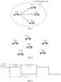
- FIG. 2 is a schematic diagram showing another communication system to which an embodiment of the present disclosure is applicable.
- Vehicle-mounted terminals (a vehicle-mounted terminal 131 and a vehicle-mounted terminal 132) autonomously select transmission resources from resources of the sidelink for data transmission.
- the vehicle-mounted terminal may select the transmission resources randomly, or select the transmission resources by means of sensing.
- sidelink communication can be categorized into sidelink communication within network coverage, as illustrated in FIG. 3 ; sidelink communication under partial network coverage, as illustrated in FIG. 4 ; and sidelink communication outside network coverage, as illustrated in FIG. 5 .
- FIG. 3 in the sidelink communication within the network coverage, all the terminals performing sidelink communication are within coverage of a same base station. Therefore, all the terminals may perform the sidelink communication based on a same sidelink configuration via receiving configuration signaling from the base station.
- FIG. 4 in a case of the sidelink communication under the partial network coverage, some terminals performing the sidelink communication are located within the coverage of the base station. These terminals may receive the configuration signaling from the base station and perform the sidelink communication based on a configuration of the base station. However, terminals outside the network coverage are incapable of receiving the configuration signaling from the base station. In this case, the terminals outside the network coverage determine a sidelink configuration for the sidelink communication based on pre-configuration information and information carried in a Physical Sidelink Broadcast Channel (PSBCH) that is transmitted by the terminals within the network coverage.
- PSBCH Physical Sidelink Broadcast Channel
- FIG. 5 for the sidelink communication outside the network coverage, all the terminals that perform the sidelink communication are located outside the network coverage, in which case all the terminals determine the sidelink configuration for the sidelink communication based on the pre-configuration information.
- D2D communication is a sidelink (SL) transmission technology based on terminal to terminal, which is different from a manner in which communication data is received or transmitted by a base station in a conventional cellular system, and thus has higher spectral efficiency and a lower transmission delay.
- a V2X system uses direct terminal-to-terminal communication.
- Two transmission modes are defined in the 3rd Generation Partnership Project (3GPP), which are noted as a first mode and a second mode. The embodiments of the present disclosure can be applied to the second mode.
- 3GPP 3rd Generation Partnership Project
- First mode transmission resources of the terminal are allocated by the base station.
- the terminal transmits data on the sideink based on the resources allocated by the base station.
- the base station may allocate resources for single transmission or semi-persistent transmission for the terminal.
- the terminal is located within the network coverage, and a network allocates transmission resources used for sidelink transmission to the terminal.
- a user may be in a mixed mode. That is, the user may use the first mode and the second mode simultaneously for obtaining a resource.
- a UE in a Radio Resource Control Connected (RRC_CONNECTED) state is configured with a DRX cycle, which includes an On Duration and an Opportunity for DRX.
- the On Duration may be called an Active Duration or Active Time.
- the UE receives no PDCCH to reduce power consumption.
- the Opportunity for DRX may be called an Inactive Duration or Inactive Time.
- the Opportunity for DRX may also be referred to as a DRX off duration.
- the terminal controls an On Duration and an Off Duration of the terminal based on timer parameters configured by a network.
- the terminal for a purpose of energy saving, it is considered to introduce a DRX mechanism to the SL, i.e., SL DRX. Similar to the DRX mechanism of the Uu interface, the SL-relevant DRX mechanism allows the terminal to receive data transmitted by other terminals in the On Duration, and enter a sleep state in the DRX Off Duration when no data is detected, aiming to lower power consumption.
- a duration when the terminal is in the On Duration is determined by a DRX configuration parameter drx_onDurationTimer.
- the terminal treats all available resources in the selection window as a set A, and performs an exclusion operation on the resources in the set A.
- the present disclosure provides a sensing scheme that can meet the sensing demand of NR-V2X in the resource selection process.
- FIG. 11 is a schematic flowchart illustrating a sensing method 200 according to an embodiment of the present disclosure. As illustrated in FIG. 11 , the sensing method 200 includes at least some of the following disclosure.
- the terminal device performs sensing based on the configuration information.
- the terminal device may perform the sensing based on the set of periodicity values for the periodic reservation allowed for the target resource pool and/or the periodicity value for sensing by the terminal device. Therefore, periodicity values selected by the terminal device for the sensing in the resource selection process are all supported by the terminal device, which meet the sensing demand of NR-V2X in the resource selection process.
- the periodicity values for the periodic reservation allowed for the target resource pool may also be called resource reservation periods.
- the embodiments of the present disclosure may be applied to partial sensing.
- the periodicity values for the periodic reservation supported by NR-V2X include ⁇ 1:99, 100, 200, 300, 400, 500, 600, 700, 800, 900, 1,000 ⁇ ms, where 1:99 represents all integer values from 1 to 99.
- the set of periodicity values for the periodic reservation allowed for a current resource pool may be indicated in the resource pool configuration information.
- the set includes up to sixteen elements. When an element in the set takes a value of 0, it indicates that the current resource pool supports aperiodic service transmission. That is, no periodic reservations are made.
- the target resource pool supports the aperiodic service transmission when the set of periodicity values allowed for the target resource pool includes 0 ms.
- the configuration information may include a sidelink resource reservation period (SL-ResourceReservePediod), which is used to indicate the set of periodicity values for the periodic reservation allowed for the target resource pool.
- SL-ResourceReservePediod a sidelink resource reservation period
- the periodicity value for sensing by the terminal device is used to indicate a periodicity value, based on which the terminal device performs the sensing. For example, when the periodicity value for sensing by the terminal device is 100 ms or 200 ms, the terminal device needs to sense slots corresponding to y-100 ms and corresponding to y-200 ms in a case where the terminal device needs to determine whether a resource is available on a slot y.
- the terminal device selects the at least Y slots in the selection window based on a minimum number of candidate slots in the target resource pool.
- the terminal device may determine the minimum number of candidate slots based on a priority of data to be transmitted and/or a Channel Busy Ratio (CBR).
- CBR Channel Busy Ratio
- the terminal device may also determine the minimum number of candidate slots based on an energy saving level.
- the energy saving level is determined based on a capacity of the terminal device and/or a remaining battery level of the terminal device.
- the minimum number of candidate slots may also be a parameter in the configuration information. That is, the configuration information may also include the minimum number of candidate slots.
- the terminal device triggers a resource selection or a resource reselection at a time point n, and a position of the selection window is determined to be [ n + T 1 , n + T 2 ].
- the terminal device selects 10 slots from a range of slots [n+10, n+19]. For any of the 10 slots, the terminal device senses the slot t y ⁇ P s SL in the sensing window.
- the terminal device selects at least Y slots in a selection window, Y being a positive integer.
- the terminal device refrains from sensing any resource on a slot t y ⁇ P s ′ SL when y - P s ' is greater than or equal to 0; or the terminal device senses a resource on a slot t y ⁇ P s ′ SL when y - P s ' is smaller than 0; or the terminal device senses the resource on the slot t y ⁇ P s ′ SL when y - P s ' is smaller than 0 and the slot t y ⁇ P s ′ SL is located within a sensing window, where t y SL represents a slot y for sidelink transmission, the slot y being any one of the at least Y slots; t y ⁇ P s ′ SL represents a slot y - P s ' for sidelink transmission; P s ' represents a number of logical
- the target slot is a slot located within a sensing window among Q slots corresponding to t y ⁇ q ⁇ P s ′ SL , or the target slot is the last one of slots located within the sensing window among the Q slots corresponding to t y ⁇ q ⁇ P s ′ SL , where T s represents a number of milliseconds corresponding to an end position of the selection window; t y SL represents a slot y for sidelink transmission, the slot y being any one of the at least Y slots; t y ⁇ q ⁇ P s ′ SL represents a slot y - q * P s ' for sidelink transmission; P s ' represents a number of logical slots corresponding to P s , or P s ' represents a number of logical slots corresponding to P s in the target resource pool; P s represents any non-zero periodicity value in the set of periodicity values allowed for the target resource pool, or P s represents the
- the terminal device performs the resource selection at a slot n, and the selection window is determined to be [n+4, n+100], where 4 and 100 represent a 4-th slot and a 100-th slot after the slot n, respectively.
- Embodiment 5 can be applied to the above-mentioned Embodiments 1 to 4. That is, in Embodiment 1, when t y ⁇ P s SL does not belong to the target resource pool, the terminal device senses the first slot belonging to the target resource pool after the slot t y ⁇ P s SL or senses the first slot belonging to the target resource pool before the slot t y ⁇ P s SL ; in Embodiment 2 or Embodiment 3, when t y ⁇ P s ′ SL does not belong to the target resource pool, the terminal device senses the first slot belonging to the target resource pool after the slot t y ⁇ P s ′ SL or senses the first slot belonging to the target resource pool before the slot t y ⁇ P s ′ SL ; and in Embodiment 4, when t y ⁇ q ⁇ P s ′ SL does not belong to the target resource pool, the terminal device senses the first slot belonging to the target resource pool after the
- the terminal device may select the at least Y slots based on DRX configuration information of the terminal device.
- the terminal device determines a first time range based on the DRX configuration information of the terminal device, and selects the at least Y slots based on the first time range.
- the terminal device is in a DRX ON state during the first time range.
- the at least Y slots include all slots within the first time range.
- the at least Y slots belonging to the first time range includes the at least Y slots including Z slots.
- the Z slots are first Z slots within the first time range, Z being a positive integer.
- the first timer is a sidelink DRX duration timer (sl-drx-onDurationTimer).
- the terminal device is in the DRX ON state during the duration started from the start position of the DRX cycle indicated by the first timer.
- the terminal device may perform the sensing based on the set of periodicity values for the periodic reservation allowed for the target resource pool and/or the periodicity value for sensing by the terminal device. Therefore, periodicity values selected by the terminal device for the sensing in the resource selection process are all supported by the terminal device, which meet the sensing demand of NR-V2X in the resource selection process.
- only slots corresponding to one period before a selected slot need to be sensed within the sensing window.
- the sensing may be performed for reservation periodicity values supported by the target resource pool.
- the transmission resource is selected based on the sensing result.
- FIG. 14 illustrates a schematic block diagram of a terminal device 300 according to an embodiment of the present disclosure.
- the terminal device 300 includes a processing unit 310 and a communication unit 320.
- the processing unit 310 is configured to obtain configuration information.
- the configuration information includes a set of periodicity values for periodic reservation allowed for a target resource pool and/or a periodicity value for sensing by the terminal device.
- the communication unit 320 is configured to perform sensing based on the configuration information.
- the processing unit 310 is further configured to select at least Y slots in a selection window, Y being a positive integer; and the communication unit 320 is specifically configured to sense a resource on a slot t y ⁇ P s SL for sidelink transmission, where t y SL represents a slot y for sidelink transmission, the slot y being any one of the at least Y slots; t y ⁇ P s SL represents a slot y - P s for sidelink transmission; and P s represents any non-zero periodicity value in the set of periodicity values allowed for the target resource pool, or P s represents the periodicity value for sensing by the terminal device.
- the processing unit 310 is further configured to select at least Y slots in a selection window, Y being a positive integer; and the communication unit 320 is specifically configured to sense a resource on a slot t y ⁇ P s ′ SL for sidelink transmission, where t y SL represents a slot y for sidelink transmission, the slot y being any one of the at least Y slots; t y ⁇ P s ′ SL represents a slot y - P s ' for sidelink transmission; P s ' represents a number of logical slots corresponding to P s , or P s ' represents a number of logical slots corresponding to P s in the target resource pool; and P s represents any non-zero periodicity value in the set of periodicity values allowed for the target resource pool, or P s represents the periodicity value for sensing by the terminal device.
- the processing unit 310 is further configured to select at least Y slots in a selection window, Y being a positive integer; and the communication unit 320 is specifically configured to sense a resource on a slot t y ⁇ q ⁇ P s ′ SL for sidelink transmission when P s ⁇ T s ; or the communication unit 320 is specifically configured to sense a resource on a target slot for sidelink transmission when P s ⁇ T s .
- the target slot is a slot located within a sensing window among Q slots corresponding to t y ⁇ q ⁇ P s ′ SL , or the target slot is the last one of slots located within the sensing window among the Q slots corresponding to t y ⁇ q ⁇ P s ′ SL , where T s represents a number of milliseconds corresponding to an end position of the selection window; t y SL represents a slot y for sidelink transmission, the slot y being any one of the at least Y slots; t y ⁇ q ⁇ P s ′ SL represents a slot y - q * P s ' for sidelink transmission; P s ' represents a number of logical slots corresponding to P s , or P s ' represents a number of logical slots corresponding to P s in the target resource pool; P s represents any non-zero periodicity value in the set of periodicity values allowed for the target resource pool, or P s represents the
- the processing unit 310 is further configured to select at least Y slots in a selection window, Y being a positive integer; the processing unit 310 is further configured to determine to sense a resource on a slot t y ⁇ P s ′ SL for sidelink transmission; and the communication unit 320 is specifically configured to sense, when the slot t y ⁇ P s ′ SL does not belong to the target resource pool, the first slot belonging to the target resource pool after the slot t y ⁇ P s ′ SL , or the communication unit 320 is specifically configured to sense, when the slot t y ⁇ P s ′ SL does not belong to the target resource pool, the first slot belonging to the target resource pool before the slot t y ⁇ P s ′ SL , where t y SL represents a slot y for sidelink transmission, the slot y being any one of the at least Y slots; t y ⁇ P s ′ SL represents a slot y - P s
- the processing unit 310 is further configured to determine the minimum number of candidate slots based on an energy saving level.
- the energy saving level is determined based on a capacity of the terminal device and/or a remaining battery level of the terminal device.
- the processing unit 310 is specifically configured to select the at least Y slots based on DRX configuration information of the terminal device.
- the processing unit 310 is specifically configured to: determine a first time range based on the DRX configuration information of the terminal device, and select the at least Y slots based on the first time range.
- the terminal device is in a DRX ON state during the first time range.
- the at least Y slots belong to the first time range; or the at least Y slots include all slots within the first time range.
- the at least Y slots belonging to the first time range includes the at least Y slots including Z slots.
- the Z slots are first Z slots within the first time range, Z being a positive integer.
- the DRX configuration information of the terminal device includes at least one parameter of a first timer, a DRX cycle parameter, or a slot offset.
- the first timer is used to indicate a duration started from a start position of a DRX cycle.
- the DRX cycle parameter is used to indicate a cycle of DRX.
- the slot offset is used to determine a start time domain position of the DRX cycle.
- the set of periodicity values allowed for the target resource pool includes at least one and up to sixteen periodicity values of 0 ms, 1 ms, 2 ms, ..., 99 ms, 100 ms, 200 ms, 300 ms, 400 ms, 500 ms, 600 ms, 700 ms, 800 ms, 900 ms, or 1000 ms.
- the target resource pool supports aperiodic service transmission when the set of periodicity values allowed for the target resource pool includes 0 ms.
- different energy saving levels correspond to different periodicity values of the sensing by the terminal device; or different priorities correspond to different periodicity values of the sensing by the terminal device.
- the communication unit may be a communication interface or a transceiver, or an input/output interface of a communication chip or a system on a chip.
- the processing unit may be one or more processors.
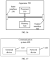
- FIG. 15 is a schematic diagram showing a structure of a communication device 400 according to an embodiment of the present disclosure.
- the communication device 400 illustrated in FIG. 15 includes a processor 410.
- the processor 410 is configured to invoke and run a computer program from a memory to implement the method according to any of the embodiments of the present disclosure.
- the communication device 400 may further include a memory 420.
- the processor 410 may invoke and run a computer program from the memory 420 to implement the method according to any of the embodiments of the present disclosure.
- the memory 420 may be a separate component independent of the processor 410, or may be integrated in the processor 410.
- the communication device 400 may further include a transceiver 430.
- the processor 410 may control the transceiver 430 to communicate with other devices, specifically, to transmit information or data to other devices, or receive information or data transmitted by other devices.
- the transceiver 430 may include a transmitter and a receiver.
- the transceiver 430 may further include one or more antennas.
- the communication device 400 may specifically be a terminal device according to an embodiment of the present disclosure.
- the communication device 400 may execute corresponding processes implemented by the terminal device in the method according to any of the embodiments of the present disclosure. For brevity, details thereof will be omitted herein.
- the apparatus 500 may further include a memory 520.
- the processor 510 may invoke and run a computer program from the memory 520 to implement the method according to any of the embodiments of the present disclosure.
- the memory 520 may be a separate component independent of the processor 510, or may be integrated in the processor 510.
- the apparatus 500 may further include an input interface 530.
- the processor 510 can control the input interface 530 to communicate with other devices or chips, specifically, to obtain information or data transmitted by other devices or chips.
- the apparatus 500 may further include an output interface 540.
- the processor 510 can control the output interface 540 to communicate with other devices or chips, specifically to output information or data to other devices or chips.
- the apparatus mentioned in the embodiments of the present disclosure may also be a chip, e.g., a system-level chip, a system-chip, a chip system, or a system-on-chip.
- a chip e.g., a system-level chip, a system-chip, a chip system, or a system-on-chip.
- the terminal device 610 can be configured to implement the corresponding functions implemented by the terminal device in the above methods.
- the network device 620 can be configured to implement corresponding functions implemented by the network device in the above methods. For brevity, details thereof will be omitted herein.
- the processor in the embodiment of the present disclosure may be an integrated circuit chip with signal processing capability.
- the steps of the above method embodiments can be implemented by hardware integrated logic circuits in a processor or instructions in the form of software.
- the processor can be a general purpose processor, a Digital Signal Processor (DSP), an Application Specific Integrated Circuit (ASIC), a Field Programmable Gate Array (FPGA) or another programmable logic device, a discrete gate or transistor logic device, or a discrete hardware component.
- DSP Digital Signal Processor
- ASIC Application Specific Integrated Circuit
- FPGA Field Programmable Gate Array
- the methods, steps, and logical block diagrams disclosed in the embodiments of the present disclosure can be implemented or performed.
- the general purpose processor may be a microprocessor or any conventional processor.
- the steps of the methods disclosed in the embodiments of the present disclosure may be directly embodied as being performed and completed by a hardware decoding processor, or by a combination of hardware and software modules in the decoding processor.
- the software modules can be located in a known storage medium in the related art, such as random access memory, flash memory, read-only memory, programmable read-only memory, electrically erasable programmable memory, or register.
- the storage medium can be located in the memory, and the processor can read information from the memory and perform the steps of the above methods in combination with its hardware.
- the memory in the embodiments of the present disclosure may be a transitory memory or a non-transitory memory, or may include both transitory and non-transitory memories.
- the non-transitory memory may be a Read-Only Memory (ROM), a Programmable ROM (PROM), an Erasable PROM (EPROM), an Electrically EPROM (EEPROM), or a flash memory.
- the transitory memory may be a Random Access Memory (RAM), which is used as an external cache.
- RAMs include for example Static RAM (SRAM), Dynamic RAM (DRAM), Synchronous DRAM (SDRAM), Double Data Rate SDRAM (DDR SDRAM), Enhanced SDRAM (ESDRAM), Synchlink DRAM (SLDRAM) ), and Direct Rambus RAM (DR RAM).
- SRAM Static RAM
- DRAM Dynamic RAM
- SDRAM Synchronous DRAM
- DDR SDRAM Double Data Rate SDRAM
- ESDRAM Enhanced SDRAM
- SLDRAM Synchlink DRAM
- DR RAM Direct Rambus RAM
- An embodiment of the present disclosure also provides a computer-readable storage medium for storing a computer program.
- the computer-readable storage medium can be applied to the network device in the embodiment of the present disclosure, and the computer program can cause a computer to perform corresponding procedures implemented by the network device in the method according to any of the embodiments of the present disclosure. Details thereof will be omitted here for simplicity.
- the computer-readable storage medium can be applied to the terminal device in the embodiment of the present disclosure, and the computer program can cause a computer to perform corresponding procedures implemented by the terminal device in the method according to any of the embodiments of the present disclosure. Details thereof will be omitted here for simplicity.
- An embodiment of the present disclosure also provides a computer program product including computer program instructions.
- the computer program product can be applied to the network device in the embodiment of the present disclosure, and the computer program instructions can cause a computer to perform corresponding procedures implemented by the network device in the method according to any of the embodiments of the present disclosure. Details thereof will be omitted here for simplicity.
- the computer program product can be applied to the terminal device in the embodiment of the present disclosure, and the computer program instructions can cause a computer to perform corresponding procedures implemented by the terminal device in the method according to any of the embodiments of the present disclosure. Details thereof will be omitted here for simplicity.
- An embodiment of the present disclosure also provides a computer program.
- the computer program can be applied to the network device in the embodiment of the present disclosure.
- the computer program when executed on a computer, can cause the computer to perform corresponding procedures implemented by the network device in the method according to any of the embodiments of the present disclosure. Details thereof will be omitted here for simplicity.
- the computer program can be applied to the terminal device in the embodiment of the present disclosure.
- the computer program when executed on a computer, can cause the computer to perform corresponding procedures implemented by the terminal device in the method according to any of the embodiments of the present disclosure. Details thereof will be omitted here for simplicity.
- the disclosed systems, devices, and methods may be implemented in other ways.
- the device embodiments described above are illustrative only.
- the divisions of the units are only divisions based on logical functions, and there may be other divisions in actual implementations.
- more than one unit or component may be combined or integrated into another system, or some features can be ignored or omitted.
- the mutual coupling or direct coupling or communicative connection as shown or discussed may be indirect coupling or communicative connection between devices or units via some interfaces which may be electrical, mechanical, or in any other forms.
- the units described as separate components may or may not be physically separated, and the components shown as units may or may not be physical units, that is, they may be co-located or distributed across a number of network elements. Some or all of the units may be selected according to actual needs to achieve the objects of the solutions of the embodiments.
- the functional units in the embodiments of the present disclosure may be integrated into one processing unit, or alternatively be separate physical modules, or two or more units may be integrated into one unit.
Landscapes
- Engineering & Computer Science (AREA)
- Computer Networks & Wireless Communication (AREA)
- Signal Processing (AREA)
- Quality & Reliability (AREA)
- Mobile Radio Communication Systems (AREA)
Applications Claiming Priority (2)
| Application Number | Priority Date | Filing Date | Title |
|---|---|---|---|
| PCT/CN2020/127152 WO2022094933A1 (zh) | 2020-11-06 | 2020-11-06 | 侦听方法和终端设备 |
| PCT/CN2021/092606 WO2022095393A1 (zh) | 2020-11-06 | 2021-05-10 | 侦听方法和终端设备 |
Publications (3)
| Publication Number | Publication Date |
|---|---|
| EP4243494A1 EP4243494A1 (en) | 2023-09-13 |
| EP4243494A4 EP4243494A4 (en) | 2024-04-24 |
| EP4243494B1 true EP4243494B1 (en) | 2025-06-25 |
Family
ID=81456904
Family Applications (1)
| Application Number | Title | Priority Date | Filing Date |
|---|---|---|---|
| EP21888097.9A Active EP4243494B1 (en) | 2020-11-06 | 2021-05-10 | Sensing method and terminal device |
Country Status (6)
| Country | Link |
|---|---|
| US (1) | US20230217317A1 (pl) |
| EP (1) | EP4243494B1 (pl) |
| CN (2) | CN115769630A (pl) |
| ES (1) | ES3037012T3 (pl) |
| PL (1) | PL4243494T3 (pl) |
| WO (2) | WO2022094933A1 (pl) |
Families Citing this family (3)
| Publication number | Priority date | Publication date | Assignee | Title |
|---|---|---|---|---|
| WO2022205437A1 (zh) | 2021-04-02 | 2022-10-06 | Oppo广东移动通信有限公司 | 部分侦听的资源选择方法、装置、设备及存储介质 |
| US12402150B2 (en) * | 2021-05-10 | 2025-08-26 | Apple Inc. | Enhanced sidelink sensing and resource allocation |
| CN115706948B (zh) * | 2021-08-05 | 2025-08-15 | 大唐移动通信设备有限公司 | 一种信息处理方法、终端及可读存储介质 |
Family Cites Families (10)
| Publication number | Priority date | Publication date | Assignee | Title |
|---|---|---|---|---|
| JP2014007732A (ja) * | 2012-05-30 | 2014-01-16 | Panasonic Corp | 端末装置 |
| US11147044B2 (en) * | 2016-03-04 | 2021-10-12 | Lg Electronics Inc. | V2X transmission resource selecting method implemented by terminal in wireless communication system and terminal using same |
| US10757550B2 (en) * | 2016-04-07 | 2020-08-25 | Lg Electronics Inc. | Method for performing sensing during terminal-specific sensing period in wireless communication system, and terminal using same |
| WO2018082062A1 (zh) * | 2016-11-04 | 2018-05-11 | 华为技术有限公司 | 资源复用方法、终端和相关设备 |
| CN106686736A (zh) * | 2016-12-30 | 2017-05-17 | 宇龙计算机通信科技(深圳)有限公司 | 一种通信资源选择方法,手持智能终端及接入设备 |
| KR102542101B1 (ko) * | 2017-08-10 | 2023-06-13 | 삼성전자 주식회사 | V2x 저지연 전송을 지원하기 위한 단말간 자원 풀 공유 방안 |
| WO2019084926A1 (zh) * | 2017-11-03 | 2019-05-09 | Oppo广东移动通信有限公司 | D2d通信中资源池共享的方法、终端设备和网络设备 |
| WO2020025040A1 (zh) * | 2018-08-03 | 2020-02-06 | Oppo广东移动通信有限公司 | 资源配置的方法和终端设备 |
| EP4440230B1 (en) * | 2020-05-09 | 2026-03-04 | Beijing Xiaomi Mobile Software Co., Ltd. | Partial sensing method and terminal device |
| CN111885619B (zh) * | 2020-06-24 | 2023-01-17 | 中国信息通信研究院 | 一种信道侦听方法、终端设备 |
-
2020
- 2020-11-06 WO PCT/CN2020/127152 patent/WO2022094933A1/zh not_active Ceased
-
2021
- 2021-05-10 PL PL21888097.9T patent/PL4243494T3/pl unknown
- 2021-05-10 CN CN202180046316.2A patent/CN115769630A/zh active Pending
- 2021-05-10 ES ES21888097T patent/ES3037012T3/es active Active
- 2021-05-10 CN CN202310460920.0A patent/CN116456494B/zh active Active
- 2021-05-10 WO PCT/CN2021/092606 patent/WO2022095393A1/zh not_active Ceased
- 2021-05-10 EP EP21888097.9A patent/EP4243494B1/en active Active
-
2022
- 2022-12-23 US US18/088,355 patent/US20230217317A1/en active Pending
Also Published As
| Publication number | Publication date |
|---|---|
| CN116456494A (zh) | 2023-07-18 |
| PL4243494T3 (pl) | 2025-09-01 |
| WO2022095393A1 (zh) | 2022-05-12 |
| WO2022094933A1 (zh) | 2022-05-12 |
| EP4243494A1 (en) | 2023-09-13 |
| ES3037012T3 (en) | 2025-09-26 |
| US20230217317A1 (en) | 2023-07-06 |
| CN115769630A (zh) | 2023-03-07 |
| EP4243494A4 (en) | 2024-04-24 |
| CN116456494B (zh) | 2025-03-25 |
Similar Documents
| Publication | Publication Date | Title |
|---|---|---|
| US12513744B2 (en) | Wireless communication method, terminal device and network device | |
| US20230217317A1 (en) | Sensing method and terminal device | |
| JP7797530B2 (ja) | チャネル混雑度の測定方法、端末機器、並びにネットワーク機器 | |
| EP4366409B1 (en) | Wireless communication method and device | |
| US12231916B2 (en) | Wireless communication method and device | |
| US20240267859A1 (en) | Wireless communication method, terminal device, and network device | |
| US20230232375A1 (en) | Method for determining resource set and terminal device | |
| CN119402875A (zh) | 无线通信方法、终端设备和网络设备 | |
| EP4271117B1 (en) | Discontinuous reception-based sensing | |
| EP4319220B1 (en) | Wireless communication method and terminal device | |
| US20230130803A1 (en) | Wireless communication method, terminal device and network device | |
| WO2024060117A1 (zh) | 无线通信的方法和终端设备 | |
| CN117242861A (zh) | 资源选择方法和终端设备 | |
| CN117397331A (zh) | 无线通信的方法和终端设备 | |
| CN117121592A (zh) | 资源选取的方法和终端设备 | |
| CN119052923A (zh) | 无线通信的方法及终端设备 |
Legal Events
| Date | Code | Title | Description |
|---|---|---|---|
| STAA | Information on the status of an ep patent application or granted ep patent |
Free format text: STATUS: THE INTERNATIONAL PUBLICATION HAS BEEN MADE |
|
| PUAI | Public reference made under article 153(3) epc to a published international application that has entered the european phase |
Free format text: ORIGINAL CODE: 0009012 |
|
| STAA | Information on the status of an ep patent application or granted ep patent |
Free format text: STATUS: REQUEST FOR EXAMINATION WAS MADE |
|
| 17P | Request for examination filed |
Effective date: 20221221 |
|
| AK | Designated contracting states |
Kind code of ref document: A1 Designated state(s): AL AT BE BG CH CY CZ DE DK EE ES FI FR GB GR HR HU IE IS IT LI LT LU LV MC MK MT NL NO PL PT RO RS SE SI SK SM TR |
|
| DAV | Request for validation of the european patent (deleted) | ||
| DAX | Request for extension of the european patent (deleted) | ||
| A4 | Supplementary search report drawn up and despatched |
Effective date: 20240326 |
|
| RIC1 | Information provided on ipc code assigned before grant |
Ipc: H04W 74/0808 20240101ALI20240320BHEP Ipc: H04W 28/26 20090101AFI20240320BHEP |
|
| GRAP | Despatch of communication of intention to grant a patent |
Free format text: ORIGINAL CODE: EPIDOSNIGR1 |
|
| STAA | Information on the status of an ep patent application or granted ep patent |
Free format text: STATUS: GRANT OF PATENT IS INTENDED |
|
| INTG | Intention to grant announced |
Effective date: 20250103 |
|
| GRAS | Grant fee paid |
Free format text: ORIGINAL CODE: EPIDOSNIGR3 |
|
| GRAA | (expected) grant |
Free format text: ORIGINAL CODE: 0009210 |
|
| STAA | Information on the status of an ep patent application or granted ep patent |
Free format text: STATUS: THE PATENT HAS BEEN GRANTED |
|
| AK | Designated contracting states |
Kind code of ref document: B1 Designated state(s): AL AT BE BG CH CY CZ DE DK EE ES FI FR GB GR HR HU IE IS IT LI LT LU LV MC MK MT NL NO PL PT RO RS SE SI SK SM TR |
|
| REG | Reference to a national code |
Ref country code: GB Ref legal event code: FG4D |
|
| REG | Reference to a national code |
Ref country code: CH Ref legal event code: EP |
|
| REG | Reference to a national code |
Ref country code: CH Ref legal event code: EP |
|
| REG | Reference to a national code |
Ref country code: IE Ref legal event code: FG4D |
|
| REG | Reference to a national code |
Ref country code: DE Ref legal event code: R096 Ref document number: 602021033077 Country of ref document: DE |
|
| REG | Reference to a national code |
Ref country code: NL Ref legal event code: FP |
|
| REG | Reference to a national code |
Ref country code: ES Ref legal event code: FG2A Ref document number: 3037012 Country of ref document: ES Kind code of ref document: T3 Effective date: 20250926 |
|
| P01 | Opt-out of the competence of the unified patent court (upc) registered |
Free format text: CASE NUMBER: UPC_APP_5162_4243494/2025 Effective date: 20250829 |
|
| PG25 | Lapsed in a contracting state [announced via postgrant information from national office to epo] |
Ref country code: FI Free format text: LAPSE BECAUSE OF FAILURE TO SUBMIT A TRANSLATION OF THE DESCRIPTION OR TO PAY THE FEE WITHIN THE PRESCRIBED TIME-LIMIT Effective date: 20250625 |
|
| REG | Reference to a national code |
Ref country code: LT Ref legal event code: MG9D |
|
| PG25 | Lapsed in a contracting state [announced via postgrant information from national office to epo] |
Ref country code: NO Free format text: LAPSE BECAUSE OF FAILURE TO SUBMIT A TRANSLATION OF THE DESCRIPTION OR TO PAY THE FEE WITHIN THE PRESCRIBED TIME-LIMIT Effective date: 20250925 Ref country code: GR Free format text: LAPSE BECAUSE OF FAILURE TO SUBMIT A TRANSLATION OF THE DESCRIPTION OR TO PAY THE FEE WITHIN THE PRESCRIBED TIME-LIMIT Effective date: 20250926 |
|
| PG25 | Lapsed in a contracting state [announced via postgrant information from national office to epo] |
Ref country code: BG Free format text: LAPSE BECAUSE OF FAILURE TO SUBMIT A TRANSLATION OF THE DESCRIPTION OR TO PAY THE FEE WITHIN THE PRESCRIBED TIME-LIMIT Effective date: 20250625 |
|
| PG25 | Lapsed in a contracting state [announced via postgrant information from national office to epo] |
Ref country code: HR Free format text: LAPSE BECAUSE OF FAILURE TO SUBMIT A TRANSLATION OF THE DESCRIPTION OR TO PAY THE FEE WITHIN THE PRESCRIBED TIME-LIMIT Effective date: 20250625 |
|
| PG25 | Lapsed in a contracting state [announced via postgrant information from national office to epo] |
Ref country code: RS Free format text: LAPSE BECAUSE OF FAILURE TO SUBMIT A TRANSLATION OF THE DESCRIPTION OR TO PAY THE FEE WITHIN THE PRESCRIBED TIME-LIMIT Effective date: 20250925 |
|
| PG25 | Lapsed in a contracting state [announced via postgrant information from national office to epo] |
Ref country code: LV Free format text: LAPSE BECAUSE OF FAILURE TO SUBMIT A TRANSLATION OF THE DESCRIPTION OR TO PAY THE FEE WITHIN THE PRESCRIBED TIME-LIMIT Effective date: 20250625 |
|
| PG25 | Lapsed in a contracting state [announced via postgrant information from national office to epo] |
Ref country code: PT Free format text: LAPSE BECAUSE OF FAILURE TO SUBMIT A TRANSLATION OF THE DESCRIPTION OR TO PAY THE FEE WITHIN THE PRESCRIBED TIME-LIMIT Effective date: 20251027 |
|
| REG | Reference to a national code |
Ref country code: AT Ref legal event code: MK05 Ref document number: 1807937 Country of ref document: AT Kind code of ref document: T Effective date: 20250625 |
|
| PG25 | Lapsed in a contracting state [announced via postgrant information from national office to epo] |
Ref country code: IS Free format text: LAPSE BECAUSE OF FAILURE TO SUBMIT A TRANSLATION OF THE DESCRIPTION OR TO PAY THE FEE WITHIN THE PRESCRIBED TIME-LIMIT Effective date: 20251025 |
|
| PG25 | Lapsed in a contracting state [announced via postgrant information from national office to epo] |
Ref country code: AT Free format text: LAPSE BECAUSE OF FAILURE TO SUBMIT A TRANSLATION OF THE DESCRIPTION OR TO PAY THE FEE WITHIN THE PRESCRIBED TIME-LIMIT Effective date: 20250625 Ref country code: SM Free format text: LAPSE BECAUSE OF FAILURE TO SUBMIT A TRANSLATION OF THE DESCRIPTION OR TO PAY THE FEE WITHIN THE PRESCRIBED TIME-LIMIT Effective date: 20250625 |
|
| PG25 | Lapsed in a contracting state [announced via postgrant information from national office to epo] |
Ref country code: CZ Free format text: LAPSE BECAUSE OF FAILURE TO SUBMIT A TRANSLATION OF THE DESCRIPTION OR TO PAY THE FEE WITHIN THE PRESCRIBED TIME-LIMIT Effective date: 20250625 |
|
| PG25 | Lapsed in a contracting state [announced via postgrant information from national office to epo] |
Ref country code: EE Free format text: LAPSE BECAUSE OF FAILURE TO SUBMIT A TRANSLATION OF THE DESCRIPTION OR TO PAY THE FEE WITHIN THE PRESCRIBED TIME-LIMIT Effective date: 20250625 |
|
| PG25 | Lapsed in a contracting state [announced via postgrant information from national office to epo] |
Ref country code: SK Free format text: LAPSE BECAUSE OF FAILURE TO SUBMIT A TRANSLATION OF THE DESCRIPTION OR TO PAY THE FEE WITHIN THE PRESCRIBED TIME-LIMIT Effective date: 20250625 |
|
| PGFP | Annual fee paid to national office [announced via postgrant information from national office to epo] |
Ref country code: GB Payment date: 20260331 Year of fee payment: 6 |
|
| PG25 | Lapsed in a contracting state [announced via postgrant information from national office to epo] |
Ref country code: DK Free format text: LAPSE BECAUSE OF FAILURE TO SUBMIT A TRANSLATION OF THE DESCRIPTION OR TO PAY THE FEE WITHIN THE PRESCRIBED TIME-LIMIT Effective date: 20250625 |
|
| PG25 | Lapsed in a contracting state [announced via postgrant information from national office to epo] |
Ref country code: IT Free format text: LAPSE BECAUSE OF FAILURE TO SUBMIT A TRANSLATION OF THE DESCRIPTION OR TO PAY THE FEE WITHIN THE PRESCRIBED TIME-LIMIT Effective date: 20250625 |