EP4243205B1 - Antenne für ein radargerät - Google Patents
Antenne für ein radargerät Download PDFInfo
- Publication number
- EP4243205B1 EP4243205B1 EP22161037.1A EP22161037A EP4243205B1 EP 4243205 B1 EP4243205 B1 EP 4243205B1 EP 22161037 A EP22161037 A EP 22161037A EP 4243205 B1 EP4243205 B1 EP 4243205B1
- Authority
- EP
- European Patent Office
- Prior art keywords
- lens element
- antenna
- feed
- signal
- feed antenna
- Prior art date
- Legal status (The legal status is an assumption and is not a legal conclusion. Google has not performed a legal analysis and makes no representation as to the accuracy of the status listed.)
- Active
Links
Images

Classifications
-
- H—ELECTRICITY
- H01—ELECTRIC ELEMENTS
- H01Q—ANTENNAS, i.e. RADIO AERIALS
- H01Q1/00—Details of, or arrangements associated with, antennas
- H01Q1/12—Supports; Mounting means
- H01Q1/22—Supports; Mounting means by structural association with other equipment or articles
-
- H—ELECTRICITY
- H01—ELECTRIC ELEMENTS
- H01Q—ANTENNAS, i.e. RADIO AERIALS
- H01Q1/00—Details of, or arrangements associated with, antennas
- H01Q1/52—Means for reducing coupling between antennas; Means for reducing coupling between an antenna and another structure
- H01Q1/521—Means for reducing coupling between antennas; Means for reducing coupling between an antenna and another structure reducing the coupling between adjacent antennas
- H01Q1/525—Means for reducing coupling between antennas; Means for reducing coupling between an antenna and another structure reducing the coupling between adjacent antennas between emitting and receiving antennas
-
- G—PHYSICS
- G01—MEASURING; TESTING
- G01S—RADIO DIRECTION-FINDING; RADIO NAVIGATION; DETERMINING DISTANCE OR VELOCITY BY USE OF RADIO WAVES; LOCATING OR PRESENCE-DETECTING BY USE OF THE REFLECTION OR RERADIATION OF RADIO WAVES; ANALOGOUS ARRANGEMENTS USING OTHER WAVES
- G01S7/00—Details of systems according to groups G01S13/00, G01S15/00, G01S17/00
- G01S7/02—Details of systems according to groups G01S13/00, G01S15/00, G01S17/00 of systems according to group G01S13/00
- G01S7/35—Details of non-pulse systems
- G01S7/352—Receivers
-
- H—ELECTRICITY
- H01—ELECTRIC ELEMENTS
- H01Q—ANTENNAS, i.e. RADIO AERIALS
- H01Q1/00—Details of, or arrangements associated with, antennas
- H01Q1/48—Earthing means; Earth screens; Counterpoises
-
- H—ELECTRICITY
- H01—ELECTRIC ELEMENTS
- H01Q—ANTENNAS, i.e. RADIO AERIALS
- H01Q1/00—Details of, or arrangements associated with, antennas
- H01Q1/50—Structural association of antennas with earthing switches, lead-in devices or lightning protectors
-
- H—ELECTRICITY
- H01—ELECTRIC ELEMENTS
- H01Q—ANTENNAS, i.e. RADIO AERIALS
- H01Q1/00—Details of, or arrangements associated with, antennas
- H01Q1/52—Means for reducing coupling between antennas; Means for reducing coupling between an antenna and another structure
-
- H—ELECTRICITY
- H01—ELECTRIC ELEMENTS
- H01Q—ANTENNAS, i.e. RADIO AERIALS
- H01Q15/00—Devices for reflection, refraction, diffraction or polarisation of waves radiated from an antenna, e.g. quasi-optical devices
- H01Q15/0006—Devices acting selectively as reflecting surface, as diffracting or as refracting device, e.g. frequency filtering or angular spatial filtering devices
- H01Q15/006—Selective devices having photonic band gap materials or materials of which the material properties are frequency dependent, e.g. perforated substrates, high-impedance surfaces
-
- H—ELECTRICITY
- H01—ELECTRIC ELEMENTS
- H01Q—ANTENNAS, i.e. RADIO AERIALS
- H01Q15/00—Devices for reflection, refraction, diffraction or polarisation of waves radiated from an antenna, e.g. quasi-optical devices
- H01Q15/02—Refracting or diffracting devices, e.g. lens, prism
-
- H—ELECTRICITY
- H01—ELECTRIC ELEMENTS
- H01Q—ANTENNAS, i.e. RADIO AERIALS
- H01Q19/00—Combinations of primary active antenna elements and units with secondary devices, e.g. with quasi-optical devices, for giving the antenna a desired directional characteristic
- H01Q19/06—Combinations of primary active antenna elements and units with secondary devices, e.g. with quasi-optical devices, for giving the antenna a desired directional characteristic using refracting or diffracting devices, e.g. lens
- H01Q19/062—Combinations of primary active antenna elements and units with secondary devices, e.g. with quasi-optical devices, for giving the antenna a desired directional characteristic using refracting or diffracting devices, e.g. lens for focusing
-
- H—ELECTRICITY
- H01—ELECTRIC ELEMENTS
- H01Q—ANTENNAS, i.e. RADIO AERIALS
- H01Q19/00—Combinations of primary active antenna elements and units with secondary devices, e.g. with quasi-optical devices, for giving the antenna a desired directional characteristic
- H01Q19/10—Combinations of primary active antenna elements and units with secondary devices, e.g. with quasi-optical devices, for giving the antenna a desired directional characteristic using reflecting surfaces
-
- H—ELECTRICITY
- H01—ELECTRIC ELEMENTS
- H01Q—ANTENNAS, i.e. RADIO AERIALS
- H01Q5/00—Arrangements for simultaneous operation of antennas on two or more different wavebands, e.g. dual-band or multi-band arrangements
- H01Q5/40—Imbricated or interleaved structures; Combined or electromagnetically coupled arrangements, e.g. comprising two or more non-connected fed radiating elements
- H01Q5/45—Imbricated or interleaved structures; Combined or electromagnetically coupled arrangements, e.g. comprising two or more non-connected fed radiating elements using two or more feeds in association with a common reflecting, diffracting or refracting device
-
- H—ELECTRICITY
- H01—ELECTRIC ELEMENTS
- H01Q—ANTENNAS, i.e. RADIO AERIALS
- H01Q9/00—Electrically-short antennas having dimensions not more than twice the operating wavelength and consisting of conductive active radiating elements
- H01Q9/04—Resonant antennas
- H01Q9/0407—Substantially flat resonant element parallel to ground plane, e.g. patch antenna
- H01Q9/045—Substantially flat resonant element parallel to ground plane, e.g. patch antenna with particular feeding means
Definitions
- the example and non-limiting embodiments of the present invention relate to an antenna assembly for a radar apparatus and/or to a radar apparatus employing the antenna assembly.
- a radar is a detection system that applies radio frequency (RF) waves for detecting targets at distant locations via using a transmitter to transmit radio waves, a receiver to receive reflections of the transmitted radio waves from remote targets, and a processing system for determining characteristics of the remote targets (such as their locations and velocities) based on the received radio waves.
- the radio waves reflected from the remote targets may be also referred to as backscattered radio waves or as backscattered RF signal.
- Radars find use in a wide range of different applications, including monitoring location and movement of distinct objects such as road vehicles, aircrafts, marine vessels as well as observing evolution of atmospheric and meteorological parameters.
- a radar intended e.g. for atmospheric and/or meteorological applications aims at observing a plurality of relatively small targets at relatively long distances from the radar and, subsequently, estimating their characteristics in an accurate and reliable manner.
- the characteristics of targets under consideration may include their respective shapes and sizes, their respective distances from the radar, and their respective movement with respect to the radar.
- the radar may aim at estimating such target characteristics for large quantities of targets distributed in the atmosphere at distances that may extend from a few meters e.g. up to a few hundred kilometers.
- Figure 1A illustrates a block diagram of some components of a radar apparatus while also schematically illustrating some aspects of operation of the radar apparatus.
- the radar apparatus of Figure 1A includes an antenna assembly 10 comprising a feed antenna 11 and a lens element 12.
- Figure 1B schematically illustrates a cross-sectional view to the antenna assembly 10 according to an example, showing the lens element 12 having a convex (e.g. substantially ellipsoidal) front end and a planar back end, where the feed antenna is arranged on the back end of the lens element 12 at a phase center 14 of the lens element 12.
- the feed antenna 11 is coupled via a coupler 25 to a transmitter 20, which supplies a RF signal for transmission as the radio waves from the feed antenna 11.
- the feed antenna 11 is further coupled via the coupler 25 to a receiver 30, which receives a RF signal captured at the feed antenna 11.
- the coupler 25 enables highly efficient respective signal paths between the transmitter 20 and the feed antenna 11 and between the feed antenna 11 and the receiver 30 while serving to prevent power of the transmitted RF signal from entering the receiver 30, thereby providing isolation between the transmitted and received RF signals.
- the transmitter 20 and the receiver 30 are coupled to a processing unit 50 arranged for controlling respective operation of the transmitter 20 and the receiver 30 and for processing the transmitted and received RF signals.
- the lens element 12 serves as a converging lens arranged to collimate radio waves transmitted (TX) from the feed antenna 11 into a sequence of waves 13a of a RF beam 13 transmitted from the antenna assembly 10 and to focus radio waves received (RX) at the antenna assembly 10 to the feed antenna 11.
- TX radio waves transmitted
- RX radio waves received
- the sequence of waves 13a that represent the RF signal supplied from the transmitter 20 to the feed antenna 11 results in a corresponding series of backscattered (or reflected, echoed) waves 43a that may be received at the antenna assembly 10 and captured at the feed antenna 11 in the received RF signal that is supplied to the receiver 30, whereas the processing unit 50 may derive various characteristics of detected targets based on the transmitted and received RF signals.
- a portion of the front end of the lens element 12 that is available for transmission and reception of radio waves may be referred to as a (mechanical) antenna aperture, whereas a portion of the (mechanical) antenna aperture that is actually applied for transmission and reception of the radio waves may be referred to as an effective antenna aperture.
- the size of the (mechanical) antenna aperture and the effective antenna aperture may be defined, for example, via the diameter of its projection (e.g. its cross-section).
- the antenna design can be optimized towards the maximal mechanical antenna aperture permitted by the application.
- the lens element 12 has a well-defined phase center 14 at which the feed antenna 11 can be positioned, where physical dimensions of the lens element 12 follow from the electrical properties of the material of the lens element 12.
- the choice of material follows from considerations regarding sufficiently low losses (e.g. high transparency and low reflections at boundaries), regarding high permittivity (focusing power) and regarding any application specific constraints concerning lens element 12 characteristics such as weight, cost and robustness to different usage environments.
- sufficiently low losses e.g. high transparency and low reflections at boundaries
- high permittivity focusing power
- any application specific constraints concerning lens element 12 characteristics such as weight, cost and robustness to different usage environments.
- There is a tendency to favor materials of relatively low permittivity which leads to relatively lengthy geometric shapes of the lens element 12.
- the shape of the lens element 12 is prolongated by a large eccentricity (e.g. a large degree of ellipticity) and by a longish cylindrical extension part of the lens element 12.
- the coupler 25 may be applied to ensure sufficient isolation between the transmitted and received RF signals.
- the requirement of isolation is present in radar systems utilizing pulsed operation of transmission as well as in frequency modulated continuous wave (FMCW) radars.
- FMCW frequency modulated continuous wave
- the time multiplexing scheme of pulsed radar allows signals to be received while transmission is paused.
- dedicated components such as an isolator and/or a limiter are needed to protect the receiver from high intensity RF power during the transmitted pulse.
- a target 40 cannot be observed in a dead zone, in terms of distance from the antenna assembly 10 corresponding to a combined traveling distance of the radio waves emitted from the antenna assembly 10 to the target 40 and traveling distance of the waves scattered back to the antenna assembly 10 from the target during the transmission and the subsequent receiver recovery period.
- the issue with the dead zone may be addressed at least to some extent via application of a frequency modulated continuous wave (FMCW) radar.
- FMCW frequency modulated continuous wave
- the transmission and reception take place simultaneously, thereby basically enabling detection of the target 40 also when it is in close proximity of the antenna assembly 10.
- the issue with sufficient isolation between the transmitted and received RF signals needs to be addressed to ensure sufficient detection performance.
- other known solutions in this regard include e.g. the following:
- EP 3490062 A1 discloses a radar device that includes: a case having an opening at the front in a forward direction, which is a transmission direction of electromagnetic waves; a circuit board placed in the case, the circuit board having first and second circuit board parts, one component side of the first circuit board part facing in the forward direction, the component sides of the second circuit board part extending along the forward direction; a transmission antenna and reception antenna composed of a plurality of antenna elements placed into an array in a direction crossing the forward direction in an area, facing in the forward direction, on the circuit board; and a dielectric lens having a semi-cylindrical or parabolic cylindrical shape in the forward direction, the dielectric lens being placed in the opening in the case so as to extend along a direction in which the plurality of antenna elements are placed into an array.
- US 2012/146882 A1 discloses a radar sensor for motor vehicles, having a source of radar radiation and a lens, which is situated in front of the source, is made of a material that refracts radar radiation and has a convex surface on at least one side, wherein the convex surface has a greater curvature in elevation than in azimuth.
- US 2008/091380 A1 discloses a velocity sensor having a reduced detection error.
- a sensor circuit unit generates an electromagnetic wave and emits it from a transmission antenna. Furthermore, a reception antenna receives a reflection wave from the ground and a mixer mixes it with a local signal, thereby generating a low-frequency signal.
- the electromagnetic wave emitted from the sensor circuit unit shapes a beam by a dielectric lens before emitting it toward the ground.
- the beam shape is such that the beam width in the vicinity of the sensor is smaller than the beam width in the vicinity of the ground.
- US 2010/328779 A1 discloses an antenna element suitable for integrated arrays at terahertz frequencies.
- the antenna element comprises an extended spherical (e.g. hemispherical) semiconductor lens, e.g. silicon, antenna fed by a leaky wave waveguide feed.
- the extended spherical lens comprises a substantially spherical lens adjacent a substantially planar lens extension.
- a couple of TE/TM leaky wave modes are excited in a resonant cavity formed between a ground plane and the substantially planar lens extension by a waveguide block coupled to the ground plane. Due to these modes, the primary feed radiates inside the lens with a directive pattern that illuminates a small sector of the lens.
- the antenna structure is compatible with known semiconductor fabrication technology and enables production of large format imaging arrays.
- US 6,590,544 B1 discloses a dielectric lens assembly that includes a dielectric extension on a hemispherical dielectric lens to provide a dielectric lens which exhibits properties of an elliptical lens.
- the extended dielectric lens can be implemented with a feed antenna to improve the directivity of the antenna.
- the extension portion of the lens assembly is fabricated using a plurality of dielectric wafers disposed on the bottom surface of the hemisphere, an angled extension, or a cylindrical extension.
- the entire hemispherical lens and extension assembly can be a single piece of dielectric material formed into the desired shape, or the assembly can be fabricated using a plurality of dielectric components coupled together to form the lens assembly.
- an antenna assembly for a radar apparatus for meteorological and/or atmospheric studies comprising: a first feed antenna arranged to transmit outbound radio waves of a transmitter beam based on a transmitted RF signal supplied thereto and a second feed antenna arranged to capture a received RF signal based on inbound radio waves of a receiver beam received thereat; and an axially symmetric lens element arranged to collimate the transmitter beam obtained via a back end of the lens element for transmission from a front end of the lens element to a monitoring direction and to focus the receiver beam received at the front end of the lens element from the monitoring direction for reception via the back end of the lens element at the second feed antenna, where a center axis of the lens element also serves as its symmetry axis, wherein the first and second feed antennas are disposed on a conductive ground plane that is perpendicular to the center axis of the lens element such that the conductive ground plane and each of the first and second feed antennas are offset from the
- a radar apparatus comprising an antenna assembly according to the example embodiment described in the foregoing and a transmitter arranged to supply the transmitted RF signal to the first feed antenna and a receiver arranged to receive the received RF signal captured at the second feed antenna; and a processing unit arranged to determine, based on the received RF signal in consideration of the transmitted RF signal, respective characteristics of one or more targets at distance from the antenna assembly in the monitoring direction, wherein said characteristics include at least one of the following: respective locations of the one or more targets, respective velocities of the one or more targets, respective sizes of the one or more targets, respective shapes of the one or more targets.
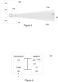
- FIG. 2 illustrates a radar apparatus 100 according to an example, including a schematic illustration of some components of an antenna assembly 110 together with a block diagram of some (other) components of the radar apparatus 100.
- the radar apparatus 100 is shown in the example of Figure 2 with the antenna assembly 110, a transmitter 120, a receiver 130, and a processing unit 150.
- the radar apparatus 100 may be employed for applications where simultaneous detection and tracking of a plurality of targets is required, such as for meteorological and/or atmospheric studies.
- Figure 2 provides a simplified illustration of the radar apparatus 100, showing only components that are necessary for describing operation and various advantageous characteristics of the radar apparatus 100 and/or antenna assembly 110 according to the present disclosure, whereas a radar apparatus 100 and/or the antenna assembly 110 may include one or more components not included in the illustration of Figure 2 without departing from the scope of the present disclosure.
- the antenna assembly 110 comprises a feed antenna arrangement and a lens element 112, where the feed antenna arrangement comprises a first feed antenna 111a and second feed antenna 111b.
- the first feed antenna 111a is arranged for transmission and the second feed antenna 111b is arranged for reception
- the lens element 112 comprises a converging lens that is arranged to collimate a transmitter beam 113a received via its back end for transmission from (an antenna aperture in) its front end and to focus a receiver beam 113b received at (the antenna aperture in) its front end for reception via its back end.
- the back end of the lens element 112 may be also referred to as a back surface of the lens element 112 or as a bottom of the lens element 112, whereas the front end of the lens element 112 may be also referred to as a front surface of the lens element 112 or as a top of the lens element 112.
- the first feed antenna 111a is arranged to transmit outbound radio waves of the transmitter beam 113a based on a (to be) transmitted RF signal supplied thereto from the transmitter 120, whereas the first feed antenna 111a may be positioned with respect to the lens element 112 such that the transmitter beam 113a is directed towards the lens element 112 via its back end, thereby resulting in transmission of the collimated transmitter beam 113a from the front end of the lens element 112.
- the second feed antenna 111b is arranged capture a received RF signal based on inbound radio waves of the receiver beam 113b received thereat and supply the received RF signal to the receiver 130.
- the second feed antenna 111b may be positioned with respect to the lens element 112 such that it is able to receive the receiver beam 113b via the back end of the lens element 112.
- the radar apparatus 100 is positioned such that the outbound radio waves of the transmitter beam 113a emitted from the front end of the lens element 112 are directed to a monitoring direction of interest, whereas radio waves echoed (or reflected, backscattered) from one or more targets in the monitoring direction are received as the inbound radio waves of the receiver beam 113b and captured in the received RF signal that is descriptive of respective characteristics of the one or more targets.
- the first feed antenna 111a may be coupled to the transmitter 120 via a first signal path and the second feed antenna 111b may be coupled to the receiver 130 via a second signal path that is separate and isolated from the first signal path.
- the transmitter 120 may provide the outbound RF signal to the first feed antenna 111a, whereas the receiver 130 may obtain the inbound RF signal from the second feed antenna 111b.
- Usage of the separate feed antennas 111a, 111b for transmission and reception in such arrangement with respect to the transmitter 120 and the receiver 130 eliminates the need for the (directional) coupler 25 applied in previously known solutions (cf. Figure 1A ) while enabling sufficient isolation between the transmitted and received RF signals, thereby substantially providing the functionality of the coupler 25 via an approach that results in smaller losses and that is more straightforward and affordable in design in comparison to the (directional) coupler 25.
- An entity comprising the antenna assembly 110, the transmitter 120 and the receiver 130 may be referred to as a transceiver, even though depicted in the example of Figure 2 as respective separate (logical) entities.
- the transmitter 120 and the receiver 130 may be coupled to the processing unit 150, which may be arranged to control respective operation of the transmitter 120 and the receiver 130.
- the processing unit 150 may be further arranged to implement one or more RF processing steps such as conversions between a baseband and the applied carrier frequency and to derive one or more characteristics of the one or more targets based on the received RF signal in view of the transmitted RF signal.
- the processing unit 150 may apply signal processing techniques known in the art and commonly applied for processing of radar signals to derive e.g.
- the one or more characteristics derived for each of the one or more targets may include one or more of the following:
- the radar apparatus 100 may enable simultaneously detecting and distinguishing a plurality of targets at remote locations and deriving their respective positions, velocities and one or more other characteristics (such as their shapes and/or sizes) across a wide range of distances from the radar apparatus 100 at a high accuracy and reliability.
- Various aspects of structure and operation of the antenna assembly 110 that enables such radar performance are described in the non-limiting examples provided in the following.
- the radar apparatus 100 may rely on frequency modulated continuous wave (FMCW) transmission and reception.
- the transmitter 120 and the receiver 130 may be implemented as respective elements of a Doppler transceiver that is arranged to apply frequency modulated continuous wave (FMCW) transmission and reception, which may be referred to as a FMCW Doppler transceiver.
- FMCW frequency modulated continuous wave
- the antenna assembly 110 is applicable across the RF wavelengths, in a non-limiting example a carrier wavelength in a range from a fraction of one millimeter to a few tens of millimeters, e.g. 5 millimeters, may be applied.
- Such carrier wavelengths enable usage of RF bandwidths in a range of several hundred MHz or even in a range of a few GHz (depending on the applied carrier wavelength), which in turn enables a relatively high spatial resolution that may be advantageous, for example, in meteorological or atmospheric applications e.g. for detection of precipitation particles, cloud particles and/or other constituents of ambient air as well as for detection of other objects in radar environment.
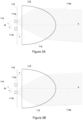
- Figures 3A and 3B schematically illustrate a cross-sectional view to the antenna assembly 110 according to an example, showing the first feed antenna 111a, the second feed antenna 111b and the lens element 112.
- the lens element 112 may comprise a suitably shaped piece of dielectric material that is transparent or substantially transparent to the respective radio waves of the transmitter beam 113a and the receiver beam 113b at wavelengths applied by the transmitter 120 and the receiver 130.
- the respective illustrations of Figures 3A and 3B are conceptual ones in the sense they serve to illustrate approximate arrangement of the first and second feed antennas 111a, 111b with respect to the lens element 112 and approximate respective shapes of the transmitter beam 113a and the receiver beam 113b resulting from such an arrangement.
- the respective illustrations of Figures 3A and 3B do not serve to illustrate any physically exact features of the antenna assembly 110 in terms of shapes and size of its components or in terms of their exact positions with respect to each other.
- the lens element 112 may be made of polyethene (PE), such as high-density polyethylene (HDPE).
- PE polyethene
- the lens element 112 may be made of cross-linked polystyrene, whereas in further examples the lens element 112 may be made of a material such as nylon, boron nitride or quartz.
- the lens element 112 serves as a converging lens.
- the lens element 112 may have a substantially circular cross-section, whereas the front end of the lens element 112 may be convex and the back end of the lens element 112 may be substantially planar.
- the convex front end of the lens element 112 may have or it may approximate an ellipsoidal shape, the front end of the lens element 112 thereby following or approximating a surface of a truncated prolate spheroid or a truncated oblate spheroid.
- the front end of the lens element 112 or a portion thereof may serve as the antenna aperture of the antenna assembly 110.
- the first feed antenna 111a is disposed at a first distance r 1 from a center axis A of the lens element 112, whereas the second feed antenna 111b is disposed at a second distance r 2 from the center axis A where each of the first distance r 1 and the second distance r 2 is set to a respective non-zero value, thereby laterally offsetting the first and second feed antennas 111a, 111b from the center axis A.
- the first feed antenna 111a is offset from the center axis A into a first direction
- the second feed antenna 111b is offset from the center axis A into a second direction, where the first and second directions are respective directions different from each other.
- the first and second directions may be opposite to each other, thereby placing the first and second feed antennas 111a, 111b at opposite sides of the center axis A at a distance r 1 + r 2 from each other.
- each of the first and second feed antennas 111a, 111b is laterally offset from the center axis A of the lens element 112. Consequently, the center axis of transmitter beam 113a exhibits a minor 'tilt' in comparison to the center axis A of the lens element 112 towards a direction that is the opposite of the first direction by an amount that at least partially depends on the first distance r 1 between the first feed antenna 111a and the center axis A.
- the center axis of the receiver beam 113b becomes 'tilted' in comparison to the center axis A of the lens element 112 towards a direction that is opposite to the second direction by an amount that at least partially depends on the second distance r 2 between the second feed antenna 111b and the center axis.
- Figures 3A and 3B depict the lens element 112 as a plano-convex lens, whereas in various examples the lens element 112 may comprise a converging lens element of any type, e.g. a plano-convex lens, a positive meniscus lens or a biconvex lens.
- the lens element 112 comprises an axially symmetric lens, where the center axis of the lens element 112 also serves as its symmetry axis.
- Figures 3A and 3B illustrate the lens element 112 as one following or approximating a shape of a truncated spheroid, whereas in other examples the lens element 112 may comprise a front portion following or approximating a shape of the truncated spheroid and a back portion that has a substantially cylindrical shape having a cross-section that is substantially the same as the cross-section of front portion, where the front and back portions may be provided as a single-piece element.
- Each of the first feed antenna 111a and the second feed antenna 111b is disposed on a (conductive) ground plane 115 that is at a predefined distance k behind the back end of the lens element 112 along the center axis A.
- the first and second feed antennas 111a, 111b are disposed on the ground plane 115 that is perpendicular to the center axis A of the lens element 112 and that is offset by a distance k from the back end of the lens element 112 in the direction of the center axis A.
- the expression 'behind the back end of the lens element 112' refers to a spatial position that is further away from the antenna aperture at the front end of the lens element 112 than the back end of the lens element 112 such that the first and second feed antennas 111a, 111b are offset from the back end of the lens element 112 by the predefined distance k in the direction of the center axis A.
- a volume between the back end of the lens element 112 and the ground plane 115 at the first and second feed antennas 111a, 111b are disposed comprises or is made of material that has a refractive index that is smaller than that of the lens element 112.
- this volume between the back end of the lens element 112 and the first and second feed antennas 111a, 111b constitutes an electromagnetic band gap (EBG), which serves to converge the transmitter beam 113a upon entry from the EBG to the lens element 112 and to focus the receiver beam 113b upon entry from the lens element 112 to the EBG:
- EBG electromagnetic band gap
- the distance k between the back end of lens element 112 and the plane 115 at which the first and second feed antennas 111a, 111b are disposed may be also referred to as a depth of the EBG (or as an EBG depth).
- the EBG may comprise an airgap or a vacuum arranged between the first and second feed antennas 111a, 111b and the back end of the lens element 112, whereas in other examples the EBG may comprise solid material having refractive index smaller than that of the material applied in the lens element 112.
- ⁇ rc denotes relative dielectric constant of the material applied for providing EBG.
- the distance k that defines the EBG depth may be substantially half of the wavelength of the applied carrier wavelength ⁇ .
- Figures 3A and 3B illustrate the position of a virtual phase center 114, which denotes the conceptual position of the phase center of the lens element 112 if excluding the convergence introduced by the EBG and which would be the position of the antenna 11 and hence position of the back end of the lens element 12 in a previously known solution described in the foregoing with references to Figures 1A and 1B .
- the virtual phase center 114 may be also referred to as an effective phase center.
- the aspect of shifting the phase center closer to the front end of the lens element 112 further facilitates reducing power leakage from the sides of the lens element 112.
- the EBG is provided as an airgap or vacuum between the ground plane 115 and the back end of the lens element 112 or where the EBG otherwise comprises or is made of material that has a density substantially smaller than that of the lens element 112
- a further advantage arising from application of the EBG is reduced weight of the antenna assembly 110.
- the EBG functionality introduces a substantial geometric space between the back end of the lens element 112 and the virtual phase center 114.
- the distinct first and second feed antennas 111a, 111b disposed on the ground plane 115 are positioned in this space, noting that the EBG depth k is relatively small in comparison to the distance between the back end of the lens element 112 and the virtual phase center 114.
- the transmitter beam 113a and the receiver beam 113b closely match respective (ideal) beams originating from the virtual phase center 114, whereas at the antenna aperture on the front end of the lens element 112 the transmitter beam 113a and the receiver beam 113b appear as if originating from the virtual phase center 114, thereby mitigating any adverse effect that may arise from offsetting at least one of the first and second feed antennas 111a, 111b from the center axis A of the lens element 112 by the respective distances r 1 and r 2 .
- the first feed antenna 111a is arranged for transmission of the outbound radio waves of the transmitter beam 113a using polarization having an orientation that is aligned in accordance with a (conceptual) line connecting respective positions of the first feed antenna 111a and the second feed antenna 111b, where the orientation of polarization is defined as the direction of E component of the electromagnetic field vectors of the transmitter beam 113a.
- the (conceptual) line that connects the respective positions of the first and second feed antennas 111a, 111b may be parallel to the projection plane of Figures 3A and 3B .
- the orientation of polarization is substantially aligned with the (conceptual) line connecting the first and second feed antennas 111a, 111b.
- the orientation of polarization of the second feed antenna 111b applied for reception is substantially aligned with the polarization of the first feed antenna 111a applied for transmission.
- This choice leads to a preferred illumination pattern at the antenna aperture, which further mitigates any tilting of the beam axes that may occur due to offsetting at least one of the first and second feed antennas 111a, 111b from the center axis A of the lens element 112 by the respective distances r 1 and r 2 .
- the antenna assembly 110 may comprise a circuit board, such as a printed circuit board (PCB) that has a first patch antenna and a second patch antenna arranged thereon, where the first patch antenna may serve as the first feed antenna 111a and the second patch antenna may serve as the second feed antenna 111b.
- the circuit board may include a conductive layer (e.g. one made of metal such as copper) serving as the ground plane 115 or the circuit board may have a conductive plate serving as the ground plane 115 arranged thereon, whereas the first and second patch antennas may be disposed on the conductive layer or on the conductive plate (whichever applies).
- the conductive layer or conductive plate may comprise or it may be made of metal such as e.g. copper.
- the spatial arrangement of the first and second patch antennas with respect to each other may follow the spatial arrangement of the first and second feed antennas 111a, 111b with respect to the center axis A of the lens element 112.
- the first patch antenna may be provided with a first conductive coupling that enables connecting the first patch antenna to the transmitter 120 and the second patch antenna may be provided with a second conductive coupling that is separate and isolated from the first conductive coupling and that enables connecting the second patch antenna to the receiver 130.
- the transmitter 120 and/or the receiver 130 may be also arranged on the circuit board, whereas in other example the transmitter 120 and/or the receiver may be provided outside the circuit board hosting the first and second patch antennas and they may be connected to the respective one of the first and second patch antennas via the respective conductive couplings.
- the circuit board hosting the first and second patch antennas may be mounted on the back side of the lens element 112 or, conversely, the back side of the lens element 112 may be mounted on the circuit board.
- the circuit board may be mounted on the back side of the lens element 112 such that the first patch antenna is disposed at the first distance r 1 from the center axis A of the lens element 112 in the first direction from the center axis A, that the second patch antenna is disposed at the second distance r 2 from the center axis A of the lens element 112 in the second direction from the center axis A, and that the first and second patch antennas are disposed on a plane that is at the distance k from the back end of the lens element 112 in the direction of the center axis A of the lens element 112, the conductive plate arranged on the surface of the circuit board thereby serving as the ground plane 115.
- the circuit board may be mounted on the back side of the lens element 112 (or vice versa) such that the first and second patch antennas serving respectively as the first and second feed antennas 111a, 111b assume their respective positions with respect to the lens element 112 in accordance with the examples described in the foregoing.
- the circuit board may have a substantially planar shape to facilitate mounting to the lens element 112.
- the lens element 112 may be provided with one or more mounting elements (e.g. mounting taps) that can be fixed to respective one or more counter-elements (e.g.
- a mounting mechanism provided by the one or more mounting elements and the one or more counter-elements is arranged to ensure correct positioning of the first and the second patch antennas of the circuit board and the lens element 112 in relation to the center axis A of the lens element 112 (i.e. the respective distances r 1 and r 2 between the center axis A and the first and second patch antennas).
- the EBG may be implemented as an airgap between conductive plate of the circuit board serving as the ground plane 115 and the back end of the lens element 112.
- the circuit board may be provided with a reinforcing element (such a metal bar or a bar made of another substantially stiff material) arranged on the opposite side of the circuit board to ensure sufficient planarity of the circuit board at the location of the first and second patch antennas and hence ensure correct distance k between the plane 115 on which the first and second patch antennas are mounted and the back end of the lens element 112.
- the lens element 112 may directly serve as the outer surface of the antenna assembly 110, thereby dispensing with the need for usage of a radome or other separate protective element for protecting the antenna assembly 110 from weather (and other) conditions that may affect the performance of the antenna assembly 110 and/or the radar apparatus 100 employing the antenna assembly 110.
- the outer surface of the lens element 112 (or one or more portions thereof) may be coated by a protective layer (e.g. a protective film) that protects the lens element 112 against oxidation that may occur due exposure to ultraviolet light in outdoor conditions.
- a protective layer e.g. a protective film
- the material of the coating is preferably selected such that coating has a dielectric constant that matches that of the lens element 112 to minimize (e.g. to reduce or even completely eliminate) backscattering of the outbound radio waves at the coated front end of the lens element 112.
- the first feed antenna 111a may be replaced with a first feed antenna group including two or more first feed antenna elements and the second feed antenna 111b may be replaced with second antenna group including two or more second feed antenna elements, arranged with respect to the center axis A of the lens element 112 such that a geometrical center point of the two or more first feed antenna elements is offset from the center axis A by the first distance r 1 and that the a geometrical center point of the two or more second feed antenna elements is offset from the center axis A by the second distance r 2 .
- the respective feed antenna elements of the first and second feed antenna groups may be implemented by respective patch antennas arranged on the circuit board.
- FIG. 4 illustrates a block diagram of some components of an apparatus 200 that may be employed to implement operations described in the foregoing with references to the processing unit 150.
- the apparatus 200 comprises a processor 210 and a memory 220.
- the memory 220 may store data and computer program code 225.
- the apparatus 200 may further comprise communication means 230 for wired or wireless communication with other apparatuses.
- the communication means 230 may enable communication with apparatuses that are provided as part of the radar apparatus 100 and/or with apparatuses that are external to the radar apparatus 100. As an example of the former, the communication means 230 may enable communication with the transmitter 120 and/or with the receiver 130.
- the apparatus may further comprise user I/O (input/output) components 240 that may be arranged, together with the processor 210 and a portion of the computer program code 225, to provide the user interface for receiving input from a user and/or providing output to the user.
- the user I/O components may include user input means, such as one or more keys or buttons, a keyboard, a touchscreen or a touchpad, etc.
- the user I/O components may include output means, such as a display or a touchscreen.
- the components of the apparatus 200 are communicatively coupled to each other via a bus 250 that enables transfer of data and control information between the components.
- the memory 220 and a portion of the computer program code 225 stored therein may be further arranged, with the processor 210, to cause the apparatus 200 to perform at least some aspects of operation of the processing unit 150 described in the foregoing.
- the processor 210 is configured to read from and write to the memory 220.
- the processor 210 is depicted as a respective single component, it may be implemented as respective one or more separate processing components.
- the memory 220 is depicted as a respective single component, it may be implemented as respective one or more separate components, some or all of which may be integrated/removable and/or may provide permanent / semi-permanent/ dynamic/cached storage.
- the computer program code 225 may comprise computer-executable instructions that implement at least some aspects of operation of the processing unit 150 described in the foregoing when loaded into the processor 210.
- the computer program code 225 may include a computer program consisting of one or more sequences of one or more instructions.
- the processor 210 is able to load and execute the computer program by reading the one or more sequences of one or more instructions included therein from the memory 220.
- the one or more sequences of one or more instructions may be configured to, when executed by the processor 210, cause the apparatus 200 to perform at least some aspects of operation of the processing unit 150 described in the foregoing.
- the apparatus 200 may comprise at least one processor 210 and at least one memory 220 including the computer program code 225 for one or more programs, the at least one memory 220 and the computer program code 225 configured to, with the at least one processor 210, cause the apparatus 200 to perform at least some aspects of operation of the processing unit 150 described in the foregoing.
- the computer program code 225 may be provided e.g. a computer program product comprising at least one computer-readable non-transitory medium having the computer program code 225 stored thereon, which computer program code 225, when executed by the processor 210 causes the apparatus 200 to perform at least some aspects of operation of the processing unit 150 described in the foregoing.
- the computer-readable non-transitory medium may comprise a memory device or a record medium such as a CD-ROM, a DVD, a Blu-ray disc or another article of manufacture that tangibly embodies the computer program.
- the computer program may be provided as a signal configured to reliably transfer the computer program.
- Reference(s) to a processor herein should not be understood to encompass only programmable processors, but also dedicated circuits such as field-programmable gate arrays (FPGA), application specific circuits (ASIC), signal processors, etc.
Landscapes
- Physics & Mathematics (AREA)
- Engineering & Computer Science (AREA)
- Computer Networks & Wireless Communication (AREA)
- General Physics & Mathematics (AREA)
- Radar, Positioning & Navigation (AREA)
- Remote Sensing (AREA)
- Electromagnetism (AREA)
- Optics & Photonics (AREA)
- Aerials With Secondary Devices (AREA)
Claims (10)
- Antennenbaugruppe (110) für ein Radargerät mit frequenzmoduliertem Dauerstrich bzw. FMCW-Radargerät (100) für meteorologische und/oder atmosphärische Studien, wobei die Antennenbaugruppe (110) Folgendes umfasst:eine erste Einspeisungsantenne (111a), eingerichtet zum Senden ausgehender Funkwellen eines Senderstrahlbündels (113a) auf der Grundlage eines dieser zugeführten gesendeten HF-Signals, eine zweite Einspeisungsantenne (111b), eingerichtet zum Aufnehmen eines empfangenen HF-Signals auf der Grundlage von eingehenden Funkwellen eines von dieser empfangenen Empfängerstrahlbündels (113b); undein axialsymmetrisches Linsenelement (112), eingerichtet zum Kollimieren des Senderstrahlbündels (113a), erhalten über ein Rückende des Linsenelements (112), zum Senden von einem Vorderende des Linsenelements (112) in einer Überwachungsrichtung und zum Fokussieren des Empfängerstrahlbündels (113b), empfangen an dem Vorderende des Linsenelements (112) aus der Überwachungsrichtung zum Empfang über das Rückende des Linsenelements (112) an der zweiten Einspeisungsantenne (111b), wobei eine Mittelachse (A) des Linsenelements (112) auch als dessen Symmetrieachse dient,wobei die erste und die zweite Einspeisungsantenne (111a, 111b) auf einer leitfähigen Masseebene (115) angeordnet sind, die senkrecht zu der Mittelachse (A) des Linsenelements (112) liegt, derart, dass die leitfähige Masseebene (115) und jede der ersten und der zweiten Einspeisungsantenne (111a, 111b) gegenüber dem Rückende des Linsenelements (112) um eine vordefinierte Distanz (k) in Richtung der Mittelachse (A) des Linsenelements (112) versetzt sind, und, wobei ein Volumen zwischen dem Rückende des Linsenelements (112) und der leitfähigen Masseebene (115) Material umfasst, das einen Brechungsindex aufweist, der kleiner als der des Linsenelements (112) ist, zum Konvergieren des ausgehenden und des eingehenden HF-Strahlbündels zwischen dem Rückende des Linsenelements (112) und der ersten und der zweiten Einspeisungsantenne (111a, 111b),wobei die vordefinierte Distanz (k) definiert ist als
 wobei λ eine für das gesendete und das empfangene HF-Signal angewandte Trägerwellenlänge bezeichnet und εrc die relative Dielektrizitätskonstante des Materials bezeichnet, das in dem Volumen zwischen der leitfähigen Masseebene (115) und dem Rückende des Linsenelements (112) eingesetzt ist,wobei die erste Einspeisungsantenne (111a) gegenüber der Mittelachse (A) des Linsenelements (112) in einer ersten Richtung um eine erste Distanz (r1) versetzt ist und die zweite Einspeisungsantenne (111b) gegenüber der Mittelachse (A) in einer zweiten Richtung um die zweite Distanz (r2) versetzt ist, wobei sich die zweite Richtung von der ersten Richtung unterscheidet, undwobei die erste Einspeisungsantenne (111a) dafür eingerichtet ist, die ausgehenden Funkwellen mit einer Polarisationsorientierung zu senden, bei der die Richtung der E-Komponente der Vektoren des elektromagnetischen Feldes des Senderstrahlbündels (113a) im Wesentlichen mit einer Konzeptionslinie ausgerichtet ist, die jeweilige Positionen der ersten Einspeisungsantenne (111a) und der zweiten Einspeisungsantenne (111b) verbindet.
 - Antennenbaugruppe (110) nach Anspruch 1, wobei die erste Einspeisungsantenne (111a) und die zweite Einspeisungsantenne (111b) an entgegengesetzten Seiten der Mittelachse (A) angeordnet sind.
- Antennenbaugruppe (110) nach Anspruch 1 oder 2, wobei die erste Distanz (r1) im Wesentlichen dieselbe wie die zweite Distanz (r2) ist.
- Antennenbaugruppe (110) nach einem der Ansprüche 1 bis 3, wobei das Vorderende des Linsenelements (112) eine konvexe Form aufweist.
- Antennenbaugruppe (110) nach einem der Ansprüche 1 bis 4, wobei das Volumen zwischen dem Rückende des Linsenelements (112) und der Masseebene (115) einen Luftspalt umfasst.
- Antennenbaugruppe (110) nach einem der Ansprüche 1 bis 5, wobei die erste Einspeisungsantenne (111a) vorgesehen ist zum Koppeln an einen Sender (120) zum Empfangen des gesendeten HF-Signals von diesem über einen ersten Signalweg und wobei die zweite Einspeisungsantenne (111b) vorgesehen ist zum Koppeln an einen Empfänger (130) zum Zuführen des empfangenen HF-Signals zu diesem über einen zweiten Signalweg, der gegenüber dem ersten Signalweg getrennt und von diesem isoliert ist.
- Radargerät (100), umfassend:eine Antennenbaugruppe (110) nach einem der Ansprüche 1 bis 6;einen Sender (120), eingerichtet zum Zuführen des gesendeten HF-Signals zu der ersten Einspeisungsantenne (111a), und einen Empfänger (130), eingerichtet zum Empfangen des empfangenen HF-Signals, das von der zweiten Einspeisungsantenne (111b) aufgenommen wurde; undeine Verarbeitungseinheit (150), eingerichtet zum Bestimmen, auf der Grundlage des empfangenen HF-Signals unter Berücksichtigung des gesendeten HF-Signals, jeweiliger Charakteristika von einem oder mehreren Zielobjekten (40) in einer Distanz von der Antennenbaugruppe (110) in der Überwachungsrichtung, wobei die Charakteristika mindestens eines der Folgenden beinhalten:jeweilige Orte des einen oder der mehreren Zielobjekte (40),jeweilige Geschwindigkeiten des einen oder der mehreren Zielobjekte (40),jeweilige Größen des einen oder der mehreren Zielobjekte (40),jeweilige Formen des einen oder der mehreren Zielobjekte (40).
- Radargerät (100) nach Anspruch 7, wobei die erste Einspeisungsantenne (111a) an den Sender (120) gekoppelt ist zum Empfangen des gesendeten HF-Signals davon über einen ersten Signalweg und wobei die zweite Einspeisungsantenne (111b) an den Empfänger (130) gekoppelt ist zum Zuführen des empfangenen HF-Signals zu diesem über einen zweiten Signalweg, der gegenüber dem ersten Signalweg getrennt und von diesem isoliert ist.
- Radargerät (100) nach Anspruch 7 oder 8, wobei der Sender (120) und der Empfänger (130) eingerichtet sind zum Anwenden von FMCW-Senden und -Empfangen.
- Radargerät (100) nach Anspruch 9, wobei der Sender (120) und der Empfänger (130) als ein Doppler-Sender-Empfänger vorgesehen sind, der dafür eingerichtet ist, das FMCW-Senden und -Empfangen anzuwenden.
Priority Applications (3)
| Application Number | Priority Date | Filing Date | Title |
|---|---|---|---|
| EP22161037.1A EP4243205B1 (de) | 2022-03-09 | 2022-03-09 | Antenne für ein radargerät |
| US18/180,000 US20230288532A1 (en) | 2022-03-09 | 2023-03-07 | Antenna for a radar apparatus |
| CN202310217668.0A CN116742336A (zh) | 2022-03-09 | 2023-03-08 | 用于雷达装置的天线 |
Applications Claiming Priority (1)
| Application Number | Priority Date | Filing Date | Title |
|---|---|---|---|
| EP22161037.1A EP4243205B1 (de) | 2022-03-09 | 2022-03-09 | Antenne für ein radargerät |
Publications (3)
| Publication Number | Publication Date |
|---|---|
| EP4243205A1 EP4243205A1 (de) | 2023-09-13 |
| EP4243205B1 true EP4243205B1 (de) | 2024-10-23 |
| EP4243205C0 EP4243205C0 (de) | 2024-10-23 |
Family
ID=80685091
Family Applications (1)
| Application Number | Title | Priority Date | Filing Date |
|---|---|---|---|
| EP22161037.1A Active EP4243205B1 (de) | 2022-03-09 | 2022-03-09 | Antenne für ein radargerät |
Country Status (3)
| Country | Link |
|---|---|
| US (1) | US20230288532A1 (de) |
| EP (1) | EP4243205B1 (de) |
| CN (1) | CN116742336A (de) |
Families Citing this family (1)
| Publication number | Priority date | Publication date | Assignee | Title |
|---|---|---|---|---|
| CN117907979B (zh) * | 2024-03-20 | 2024-07-12 | 深圳大舜激光技术有限公司 | 一种远距式测风雷达收发天线 |
Citations (2)
| Publication number | Priority date | Publication date | Assignee | Title |
|---|---|---|---|---|
| US6590544B1 (en) * | 1998-09-01 | 2003-07-08 | Qualcomm, Inc. | Dielectric lens assembly for a feed antenna |
| US20100328779A1 (en) * | 2009-06-30 | 2010-12-30 | California Institute Of Technolology | Dielectric covered planar antennas |
Family Cites Families (3)
| Publication number | Priority date | Publication date | Assignee | Title |
|---|---|---|---|---|
| JP4456998B2 (ja) * | 2004-12-28 | 2010-04-28 | 日立オートモティブシステムズ株式会社 | 速度センサおよびそれを用いた対地車速センサ |
| DE102009027433A1 (de) * | 2009-07-02 | 2011-01-05 | Robert Bosch Gmbh | Radarsensor für Kraftfahrzeuge |
| EP3490062B1 (de) * | 2017-11-27 | 2022-07-27 | Panasonic Intellectual Property Management Co., Ltd. | Radarvorrichtung |
-
2022
- 2022-03-09 EP EP22161037.1A patent/EP4243205B1/de active Active
-
2023
- 2023-03-07 US US18/180,000 patent/US20230288532A1/en active Pending
- 2023-03-08 CN CN202310217668.0A patent/CN116742336A/zh active Pending
Patent Citations (2)
| Publication number | Priority date | Publication date | Assignee | Title |
|---|---|---|---|---|
| US6590544B1 (en) * | 1998-09-01 | 2003-07-08 | Qualcomm, Inc. | Dielectric lens assembly for a feed antenna |
| US20100328779A1 (en) * | 2009-06-30 | 2010-12-30 | California Institute Of Technolology | Dielectric covered planar antennas |
Also Published As
| Publication number | Publication date |
|---|---|
| EP4243205A1 (de) | 2023-09-13 |
| CN116742336A (zh) | 2023-09-12 |
| US20230288532A1 (en) | 2023-09-14 |
| EP4243205C0 (de) | 2024-10-23 |
Similar Documents
| Publication | Publication Date | Title |
|---|---|---|
| EP3490064B1 (de) | Antennenvorrichtung | |
| US8643536B2 (en) | Radio frequency positioning system for vehicles | |
| US12487324B2 (en) | Systems and methods for providing wide beam radar arrays | |
| CN110109072A (zh) | 一种多基地海上小目标雷达探测方法 | |
| KR102545536B1 (ko) | 안테나 장치 및 이를 포함하는 레이더 | |
| US20250370099A1 (en) | Antenna for a radar apparatus | |
| US7453411B2 (en) | Antenna device and radar apparatus including the same | |
| CN108173006A (zh) | 一种适用于太赫兹波段的单脉冲卡塞格伦天线 | |
| JP2020050271A (ja) | 車載ライト装置の制御装置 | |
| EP1884801B1 (de) | System und Verfahren zur gezielten Erkennung mittels einer Radarantenne | |
| EP4243205B1 (de) | Antenne für ein radargerät | |
| Jha | The millimeter Wave (mmW) radar characterization, testing, verification challenges and opportunities | |
| CN118645809A (zh) | 收发分置一维相控阵天线及其设计方法 | |
| Jansen | Automotive radar sensor for ultra short range applications | |
| KR20240091574A (ko) | 레이더 장치의 레이돔 설계방법, 그를 이용한 레이돔과 레이더 장치 | |
| US20250309550A1 (en) | Radio wave lens, radio wave lens apparatus, and radar apparatus | |
| WO2025158757A1 (ja) | アンテナ装置、及び、レーダ装置 | |
| JP2012222545A (ja) | レンズアンテナ、及びレーダ装置 | |
| US20170336506A1 (en) | Range-independent resolution RADAR | |
| KR102207395B1 (ko) | 차량용 레이더 및 그 제어 방법 | |
| US11867804B2 (en) | Apparatus and method for measuring precipitation | |
| EP4496126A1 (de) | Kompakte, hybride, kostengünstige, hochauflösende phasengesteuerte doppelmodus-gruppenantenne | |
| Zhang et al. | Jamming Against Phased Array Radar | |
| Muppala et al. | Single Transceiver 3-D Radar Imaging at 80 GHz Via Affine Phase Center Translations | |
| CN108370091A (zh) | 天线以及包括这种天线的防碰撞检测系统 |
Legal Events
| Date | Code | Title | Description |
|---|---|---|---|
| STAA | Information on the status of an ep patent application or granted ep patent |
Free format text: STATUS: EXAMINATION IS IN PROGRESS |
|
| PUAI | Public reference made under article 153(3) epc to a published international application that has entered the european phase |
Free format text: ORIGINAL CODE: 0009012 |
|
| 17P | Request for examination filed |
Effective date: 20221125 |
|
| AK | Designated contracting states |
Kind code of ref document: A1 Designated state(s): AL AT BE BG CH CY CZ DE DK EE ES FI FR GB GR HR HU IE IS IT LI LT LU LV MC MK MT NL NO PL PT RO RS SE SI SK SM TR |
|
| GRAP | Despatch of communication of intention to grant a patent |
Free format text: ORIGINAL CODE: EPIDOSNIGR1 |
|
| STAA | Information on the status of an ep patent application or granted ep patent |
Free format text: STATUS: GRANT OF PATENT IS INTENDED |
|
| INTG | Intention to grant announced |
Effective date: 20240515 |
|
| GRAS | Grant fee paid |
Free format text: ORIGINAL CODE: EPIDOSNIGR3 |
|
| GRAA | (expected) grant |
Free format text: ORIGINAL CODE: 0009210 |
|
| STAA | Information on the status of an ep patent application or granted ep patent |
Free format text: STATUS: THE PATENT HAS BEEN GRANTED |
|
| AK | Designated contracting states |
Kind code of ref document: B1 Designated state(s): AL AT BE BG CH CY CZ DE DK EE ES FI FR GB GR HR HU IE IS IT LI LT LU LV MC MK MT NL NO PL PT RO RS SE SI SK SM TR |
|
| REG | Reference to a national code |
Ref country code: GB Ref legal event code: FG4D |
|
| REG | Reference to a national code |
Ref country code: CH Ref legal event code: EP |
|
| REG | Reference to a national code |
Ref country code: DE Ref legal event code: R096 Ref document number: 602022006948 Country of ref document: DE |
|
| REG | Reference to a national code |
Ref country code: IE Ref legal event code: FG4D |
|
| U01 | Request for unitary effect filed |
Effective date: 20241121 |
|
| U07 | Unitary effect registered |
Designated state(s): AT BE BG DE DK EE FI FR IT LT LU LV MT NL PT RO SE SI Effective date: 20241127 |
|
| PG25 | Lapsed in a contracting state [announced via postgrant information from national office to epo] |
Ref country code: IS Free format text: LAPSE BECAUSE OF FAILURE TO SUBMIT A TRANSLATION OF THE DESCRIPTION OR TO PAY THE FEE WITHIN THE PRESCRIBED TIME-LIMIT Effective date: 20250223 Ref country code: HR Free format text: LAPSE BECAUSE OF FAILURE TO SUBMIT A TRANSLATION OF THE DESCRIPTION OR TO PAY THE FEE WITHIN THE PRESCRIBED TIME-LIMIT Effective date: 20241023 |
|
| U20 | Renewal fee for the european patent with unitary effect paid |
Year of fee payment: 4 Effective date: 20250313 |
|
| PG25 | Lapsed in a contracting state [announced via postgrant information from national office to epo] |
Ref country code: ES Free format text: LAPSE BECAUSE OF FAILURE TO SUBMIT A TRANSLATION OF THE DESCRIPTION OR TO PAY THE FEE WITHIN THE PRESCRIBED TIME-LIMIT Effective date: 20241023 |
|
| PG25 | Lapsed in a contracting state [announced via postgrant information from national office to epo] |
Ref country code: NO Free format text: LAPSE BECAUSE OF FAILURE TO SUBMIT A TRANSLATION OF THE DESCRIPTION OR TO PAY THE FEE WITHIN THE PRESCRIBED TIME-LIMIT Effective date: 20250123 |
|
| PG25 | Lapsed in a contracting state [announced via postgrant information from national office to epo] |
Ref country code: GR Free format text: LAPSE BECAUSE OF FAILURE TO SUBMIT A TRANSLATION OF THE DESCRIPTION OR TO PAY THE FEE WITHIN THE PRESCRIBED TIME-LIMIT Effective date: 20250124 |
|
| PG25 | Lapsed in a contracting state [announced via postgrant information from national office to epo] |
Ref country code: PL Free format text: LAPSE BECAUSE OF FAILURE TO SUBMIT A TRANSLATION OF THE DESCRIPTION OR TO PAY THE FEE WITHIN THE PRESCRIBED TIME-LIMIT Effective date: 20241023 |
|
| PG25 | Lapsed in a contracting state [announced via postgrant information from national office to epo] |
Ref country code: RS Free format text: LAPSE BECAUSE OF FAILURE TO SUBMIT A TRANSLATION OF THE DESCRIPTION OR TO PAY THE FEE WITHIN THE PRESCRIBED TIME-LIMIT Effective date: 20250123 |
|
| PG25 | Lapsed in a contracting state [announced via postgrant information from national office to epo] |
Ref country code: SM Free format text: LAPSE BECAUSE OF FAILURE TO SUBMIT A TRANSLATION OF THE DESCRIPTION OR TO PAY THE FEE WITHIN THE PRESCRIBED TIME-LIMIT Effective date: 20241023 |
|
| PG25 | Lapsed in a contracting state [announced via postgrant information from national office to epo] |
Ref country code: SK Free format text: LAPSE BECAUSE OF FAILURE TO SUBMIT A TRANSLATION OF THE DESCRIPTION OR TO PAY THE FEE WITHIN THE PRESCRIBED TIME-LIMIT Effective date: 20241023 |
|
| PG25 | Lapsed in a contracting state [announced via postgrant information from national office to epo] |
Ref country code: CZ Free format text: LAPSE BECAUSE OF FAILURE TO SUBMIT A TRANSLATION OF THE DESCRIPTION OR TO PAY THE FEE WITHIN THE PRESCRIBED TIME-LIMIT Effective date: 20241023 |
|
| PLBE | No opposition filed within time limit |
Free format text: ORIGINAL CODE: 0009261 |
|
| STAA | Information on the status of an ep patent application or granted ep patent |
Free format text: STATUS: NO OPPOSITION FILED WITHIN TIME LIMIT |
|
| 26N | No opposition filed |
Effective date: 20250724 |
|
| PG25 | Lapsed in a contracting state [announced via postgrant information from national office to epo] |
Ref country code: MC Free format text: LAPSE BECAUSE OF FAILURE TO SUBMIT A TRANSLATION OF THE DESCRIPTION OR TO PAY THE FEE WITHIN THE PRESCRIBED TIME-LIMIT Effective date: 20241023 |
|
| REG | Reference to a national code |
Ref country code: CH Ref legal event code: H13 Free format text: ST27 STATUS EVENT CODE: U-0-0-H10-H13 (AS PROVIDED BY THE NATIONAL OFFICE) Effective date: 20251023 |
|
| PG25 | Lapsed in a contracting state [announced via postgrant information from national office to epo] |
Ref country code: CH Free format text: LAPSE BECAUSE OF NON-PAYMENT OF DUE FEES Effective date: 20250331 |
|
| PG25 | Lapsed in a contracting state [announced via postgrant information from national office to epo] |
Ref country code: IE Free format text: LAPSE BECAUSE OF NON-PAYMENT OF DUE FEES Effective date: 20250309 |
|
| PGFP | Annual fee paid to national office [announced via postgrant information from national office to epo] |
Ref country code: GB Payment date: 20260324 Year of fee payment: 5 |
|
| U20 | Renewal fee for the european patent with unitary effect paid |
Year of fee payment: 5 Effective date: 20260309 |