EP4243168A1 - Batterie secondaire cylindrique - Google Patents
Batterie secondaire cylindrique Download PDFInfo
- Publication number
- EP4243168A1 EP4243168A1 EP21889407.9A EP21889407A EP4243168A1 EP 4243168 A1 EP4243168 A1 EP 4243168A1 EP 21889407 A EP21889407 A EP 21889407A EP 4243168 A1 EP4243168 A1 EP 4243168A1
- Authority
- EP
- European Patent Office
- Prior art keywords
- cap
- insulator
- cross
- linking
- assembly
- Prior art date
- Legal status (The legal status is an assumption and is not a legal conclusion. Google has not performed a legal analysis and makes no representation as to the accuracy of the status listed.)
- Pending
Links
- 238000000034 method Methods 0.000 claims abstract description 87
- 239000012212 insulator Substances 0.000 claims abstract description 85
- 238000004132 cross linking Methods 0.000 claims abstract description 46
- 238000002347 injection Methods 0.000 claims abstract description 10
- 239000007924 injection Substances 0.000 claims abstract description 10
- 239000004743 Polypropylene Substances 0.000 claims description 29
- -1 polyethylene Polymers 0.000 claims description 29
- 229920001155 polypropylene Polymers 0.000 claims description 29
- 239000000463 material Substances 0.000 claims description 26
- 239000004698 Polyethylene Substances 0.000 claims description 25
- 229920000573 polyethylene Polymers 0.000 claims description 25
- 239000005038 ethylene vinyl acetate Substances 0.000 claims description 21
- 229920001200 poly(ethylene-vinyl acetate) Polymers 0.000 claims description 21
- 239000004793 Polystyrene Substances 0.000 claims description 11
- 238000010382 chemical cross-linking Methods 0.000 claims description 11
- 230000005855 radiation Effects 0.000 claims description 7
- 239000011810 insulating material Substances 0.000 claims description 4
- 230000004927 fusion Effects 0.000 abstract description 5
- 238000002844 melting Methods 0.000 description 6
- 230000008018 melting Effects 0.000 description 6
- PXHVJJICTQNCMI-UHFFFAOYSA-N Nickel Chemical compound [Ni] PXHVJJICTQNCMI-UHFFFAOYSA-N 0.000 description 5
- 229910052782 aluminium Inorganic materials 0.000 description 5
- XAGFODPZIPBFFR-UHFFFAOYSA-N aluminium Chemical compound [Al] XAGFODPZIPBFFR-UHFFFAOYSA-N 0.000 description 5
- 238000009413 insulation Methods 0.000 description 5
- 238000003466 welding Methods 0.000 description 5
- 229910000851 Alloy steel Inorganic materials 0.000 description 4
- 229910000831 Steel Inorganic materials 0.000 description 4
- 239000003792 electrolyte Substances 0.000 description 4
- 239000010959 steel Substances 0.000 description 4
- 229910000838 Al alloy Inorganic materials 0.000 description 3
- 239000010949 copper Substances 0.000 description 3
- 238000002788 crimping Methods 0.000 description 3
- XLYOFNOQVPJJNP-UHFFFAOYSA-N water Substances O XLYOFNOQVPJJNP-UHFFFAOYSA-N 0.000 description 3
- OKTJSMMVPCPJKN-UHFFFAOYSA-N Carbon Chemical compound [C] OKTJSMMVPCPJKN-UHFFFAOYSA-N 0.000 description 2
- RYGMFSIKBFXOCR-UHFFFAOYSA-N Copper Chemical compound [Cu] RYGMFSIKBFXOCR-UHFFFAOYSA-N 0.000 description 2
- 230000005856 abnormality Effects 0.000 description 2
- 150000001875 compounds Chemical class 0.000 description 2
- 229910052802 copper Inorganic materials 0.000 description 2
- 238000010586 diagram Methods 0.000 description 2
- 230000000694 effects Effects 0.000 description 2
- 238000010894 electron beam technology Methods 0.000 description 2
- 239000011888 foil Substances 0.000 description 2
- 238000004519 manufacturing process Methods 0.000 description 2
- 239000000155 melt Substances 0.000 description 2
- 229910052759 nickel Inorganic materials 0.000 description 2
- 229910032387 LiCoO2 Inorganic materials 0.000 description 1
- 229910014549 LiMn204 Inorganic materials 0.000 description 1
- 229910003005 LiNiO2 Inorganic materials 0.000 description 1
- HBBGRARXTFLTSG-UHFFFAOYSA-N Lithium ion Chemical compound [Li+] HBBGRARXTFLTSG-UHFFFAOYSA-N 0.000 description 1
- 230000002159 abnormal effect Effects 0.000 description 1
- 229910052799 carbon Inorganic materials 0.000 description 1
- 239000003054 catalyst Substances 0.000 description 1
- 239000003431 cross linking reagent Substances 0.000 description 1
- 238000007599 discharging Methods 0.000 description 1
- 230000005611 electricity Effects 0.000 description 1
- 238000001125 extrusion Methods 0.000 description 1
- 239000010408 film Substances 0.000 description 1
- 229910002804 graphite Inorganic materials 0.000 description 1
- 239000010439 graphite Substances 0.000 description 1
- 238000001746 injection moulding Methods 0.000 description 1
- 238000003780 insertion Methods 0.000 description 1
- 230000037431 insertion Effects 0.000 description 1
- 230000001678 irradiating effect Effects 0.000 description 1
- 229910001416 lithium ion Inorganic materials 0.000 description 1
- 239000007773 negative electrode material Substances 0.000 description 1
- 229920001748 polybutylene Polymers 0.000 description 1
- 229920002223 polystyrene Polymers 0.000 description 1
- 239000007774 positive electrode material Substances 0.000 description 1
- 238000000926 separation method Methods 0.000 description 1
- 229910000077 silane Inorganic materials 0.000 description 1
- 239000000243 solution Substances 0.000 description 1
- 239000000126 substance Substances 0.000 description 1
- 239000013077 target material Substances 0.000 description 1
- 239000010409 thin film Substances 0.000 description 1
- 229910000314 transition metal oxide Inorganic materials 0.000 description 1
Images

Classifications
-
- H—ELECTRICITY
- H01—ELECTRIC ELEMENTS
- H01M—PROCESSES OR MEANS, e.g. BATTERIES, FOR THE DIRECT CONVERSION OF CHEMICAL ENERGY INTO ELECTRICAL ENERGY
- H01M50/00—Constructional details or processes of manufacture of the non-active parts of electrochemical cells other than fuel cells, e.g. hybrid cells
- H01M50/10—Primary casings; Jackets or wrappings
- H01M50/172—Arrangements of electric connectors penetrating the casing
-
- H—ELECTRICITY
- H01—ELECTRIC ELEMENTS
- H01M—PROCESSES OR MEANS, e.g. BATTERIES, FOR THE DIRECT CONVERSION OF CHEMICAL ENERGY INTO ELECTRICAL ENERGY
- H01M50/00—Constructional details or processes of manufacture of the non-active parts of electrochemical cells other than fuel cells, e.g. hybrid cells
- H01M50/10—Primary casings; Jackets or wrappings
- H01M50/183—Sealing members
- H01M50/186—Sealing members characterised by the disposition of the sealing members
-
- H—ELECTRICITY
- H01—ELECTRIC ELEMENTS
- H01M—PROCESSES OR MEANS, e.g. BATTERIES, FOR THE DIRECT CONVERSION OF CHEMICAL ENERGY INTO ELECTRICAL ENERGY
- H01M10/00—Secondary cells; Manufacture thereof
- H01M10/04—Construction or manufacture in general
- H01M10/0422—Cells or battery with cylindrical casing
-
- H—ELECTRICITY
- H01—ELECTRIC ELEMENTS
- H01M—PROCESSES OR MEANS, e.g. BATTERIES, FOR THE DIRECT CONVERSION OF CHEMICAL ENERGY INTO ELECTRICAL ENERGY
- H01M50/00—Constructional details or processes of manufacture of the non-active parts of electrochemical cells other than fuel cells, e.g. hybrid cells
- H01M50/10—Primary casings; Jackets or wrappings
- H01M50/147—Lids or covers
- H01M50/148—Lids or covers characterised by their shape
- H01M50/152—Lids or covers characterised by their shape for cells having curved cross-section, e.g. round or elliptic
-
- H—ELECTRICITY
- H01—ELECTRIC ELEMENTS
- H01M—PROCESSES OR MEANS, e.g. BATTERIES, FOR THE DIRECT CONVERSION OF CHEMICAL ENERGY INTO ELECTRICAL ENERGY
- H01M50/00—Constructional details or processes of manufacture of the non-active parts of electrochemical cells other than fuel cells, e.g. hybrid cells
- H01M50/10—Primary casings; Jackets or wrappings
- H01M50/183—Sealing members
- H01M50/19—Sealing members characterised by the material
- H01M50/193—Organic material
-
- H—ELECTRICITY
- H01—ELECTRIC ELEMENTS
- H01M—PROCESSES OR MEANS, e.g. BATTERIES, FOR THE DIRECT CONVERSION OF CHEMICAL ENERGY INTO ELECTRICAL ENERGY
- H01M50/00—Constructional details or processes of manufacture of the non-active parts of electrochemical cells other than fuel cells, e.g. hybrid cells
- H01M50/30—Arrangements for facilitating escape of gases
- H01M50/342—Non-re-sealable arrangements
- H01M50/3425—Non-re-sealable arrangements in the form of rupturable membranes or weakened parts, e.g. pierced with the aid of a sharp member
-
- H—ELECTRICITY
- H01—ELECTRIC ELEMENTS
- H01M—PROCESSES OR MEANS, e.g. BATTERIES, FOR THE DIRECT CONVERSION OF CHEMICAL ENERGY INTO ELECTRICAL ENERGY
- H01M50/00—Constructional details or processes of manufacture of the non-active parts of electrochemical cells other than fuel cells, e.g. hybrid cells
- H01M50/50—Current conducting connections for cells or batteries
- H01M50/572—Means for preventing undesired use or discharge
-
- Y—GENERAL TAGGING OF NEW TECHNOLOGICAL DEVELOPMENTS; GENERAL TAGGING OF CROSS-SECTIONAL TECHNOLOGIES SPANNING OVER SEVERAL SECTIONS OF THE IPC; TECHNICAL SUBJECTS COVERED BY FORMER USPC CROSS-REFERENCE ART COLLECTIONS [XRACs] AND DIGESTS
- Y02—TECHNOLOGIES OR APPLICATIONS FOR MITIGATION OR ADAPTATION AGAINST CLIMATE CHANGE
- Y02E—REDUCTION OF GREENHOUSE GAS [GHG] EMISSIONS, RELATED TO ENERGY GENERATION, TRANSMISSION OR DISTRIBUTION
- Y02E60/00—Enabling technologies; Technologies with a potential or indirect contribution to GHG emissions mitigation
- Y02E60/10—Energy storage using batteries
Definitions
- An embodiment of the present invention relates to a cylindrical secondary battery capable of maintaining an insulating function even in a high-temperature environment.
- a cylindrical secondary battery includes a cylindrical electrode assembly, a cylindrical can accommodating the electrode assembly and electrolyte, and a cap assembly coupled to a top opening of the can to seal the can and allow current generated in the electrode assembly to flow to an external device.
- the cap assembly may include a cap-up, a vent plate, a cap-down, and an insulator for insulation between the vent plate and the cap-down.
- the insulator In the event of a short circuit due to the rupture of the vent plate, the insulator must be able to maintain the insulating function thereof.
- the center of the vent plate may be deformed to block current, but there may be a problem that the insulator melts and re-energization occurs.
- An object of the present invention is to provide a cylindrical secondary battery capable of maintaining an insulating function even in a high-temperature environment.
- a cylindrical secondary battery may include: a cylindrical can; an electrode assembly accommodated in the cylindrical can; and a cap assembly comprising a cap-up, a cap-down disposed under the cap-up, a vent plate disposed between the cap-up and the cap-down, spaced apart from the cap-down and having at least one notch, and an insulator inserted between the vent plate and the cap-down to insulate the vent plate and the cap-down from each other, wherein the insulator is formed through an injection process, an assembly process, and a cross-linking process, sequentially.
- the assembly process may be a process in which the insulator is inserted between the vent plate and the cap-down and is then heat-sealed.
- the cross-linking process may be a process in which the heat-sealed insulator is cross-linked.
- a cross-linking treatment method used in the cross-linking process may vary depending on the material of the insulator.
- the insulator may be made of an insulating material including polyethylene (PE), polypropylene (PP), polystyrene (PS), and ethylene-vinyl acetate copolymer (EVA).
- PE polyethylene
- PP polypropylene
- PS polystyrene
- EVA ethylene-vinyl acetate copolymer
- the insulator is made of any one of polyethylene (PE) and polypropylene (PP) materials
- radiation irradiation or chemical cross-linking may be applied as the cross-linking treatment method.
- the insulator is made of any one of polystyrene (PS) and ethylene vinyl acetate copolymer (EVA), a chemical cross-linking method may be applied as the cross-linking treatment method.
- PS polystyrene
- EVA ethylene vinyl acetate copolymer
- the present invention provides a cap assembly comprising: a cap-up disposed in an opening of a cylindrical can in which an electrode assembly is accommodated; a cap-down disposed below the cap-up; a vent plate disposed between the cap-up and the cap-down, and having at least one notch formed therein; and an insulator inserted between the vent plate and the cap-down to insulate the vent plate and the cap-down from each other, wherein the insulator is formed through an injection process, an assembly process, and a cross-linking process, sequentially.
- the assembly process may be a process in which the insulator is inserted between the vent plate and the cap-down and is then heat-sealed.
- the cross-linking process may be a process in which the heat-sealed insulator is cross-linked.
- a cross-linking treatment method used in the cross-linking process may vary depending on the material of the insulator.
- the insulator may be made of an insulating material including polyethylene (PE), polypropylene (PP), polystyrene (PS), and ethylene-vinyl acetate copolymer (EVA).
- PE polyethylene
- PP polypropylene
- PS polystyrene
- EVA ethylene-vinyl acetate copolymer
- the insulator is made of any one of polyethylene (PE) and polypropylene (PP) materials
- radiation irradiation or chemical cross-linking may be applied as the cross-linking treatment method.
- the insulator is made of any one of polystyrene (PS) and ethylene vinyl acetate copolymer (EVA), a chemical cross-linking method may be applied as the cross-linking treatment method.
- PS polystyrene
- EVA ethylene vinyl acetate copolymer
- a cross-linking process is performed after the insulator is injected and fused to the cap assembly, and thus, the insulator can be stably coupled to the cap assembly.
- the insulator does not melt even in a high-temperature environment. Therefore, since the insulator can maintain an insulating function even in a high-temperature environment, there is an effect of preventing re-energization due to melting of the insulator.
- first, second, etc. may be used herein to describe various members, elements, regions, layers and/or sections, these members, elements, regions, layers and/or sections should not be limited by these terms. These terms are only used to distinguish one member, element, region, layer and/or section from another. Thus, for example, a first member, a first element, a first region, a first layer and/or a first section discussed below could be termed a second member, a second element, a second region, a second layer and/or a second section without departing from the teachings of the present invention.
- spatially relative terms such as “beneath,” “below,” “lower,” “above,” “upper,” and the like, may be used herein for ease of description to describe one element or feature's relationship to another element(s) or feature(s) as illustrated in the figures. It will be understood that the spatially relative terms are intended to encompass different orientations of the device in use or operation in addition to the orientation depicted in the figures. For example, if the element or feature in the figures is turned over, elements described as “below” or “beneath” other elements or features would then be oriented “on” or “above” the other elements or features. Thus, the exemplary term “below” can encompass both an orientation of above and below.
- FIG. 1 is a longitudinal cross-sectional view illustrating a cylindrical secondary battery according to an embodiment of the present invention.
- FIG. 2 is a longitudinal cross-sectional view illustrating a cap assembly according to FIG. 1 .
- the cylindrical secondary battery 10 may include a cylindrical can 100, an electrode assembly 300 inserted into the can 100, a cap assembly 500 inserted into one end of the can 100, and an insulating gasket 700 inserted between the can 100 and the cap assembly 500.
- a center pin 380 may be coupled to the electrode assembly 300.
- the can 100 may include a circular bottom portion 110 and a side portion 130 extending upward from the bottom portion 110, and the upper portion of the side portion 130 is open (hereinafter referred to as an opening).
- the electrode assembly 300 is inserted into the can 100 together with an electrolyte through the opening of the can 100.
- the can 100 may be made of steel, a steel alloy, nickel-plated steel, a nickel-plated steel alloy, aluminum, an aluminum alloy, or an equivalent thereof, but the material is not limited thereto.
- the cap assembly 500 is inserted into the opening of the can 100.
- a beading part 132 and a crimping part 134 may be formed on the side portion 130 to prevent the inserted cap assembly 500 from escaping to the outside through the opening of the can 100.
- the beading part 132 is formed below the cap assembly 500 and is recessed toward the inside of the can 100.
- the crimping part 134 is formed above the cap assembly 500 and is bent toward the inside of the can 100. Since the beading part 132 and the crimping part 134 hold the cap assembly 500 in the vertical direction, the cap assembly 500 is not separated from the can 100.
- the electrode assembly 300 is disposed below the cap assembly 500 inside the can 100.
- the electrode assembly 300 may include a negative electrode plate 310 coated with a negative electrode active material (e.g., graphite, carbon, etc.), a positive electrode plate 320 coated with a positive electrode active material (e.g., a transition metal oxide (LiCoO2, LiNiO2, LiMn204, etc.)), and a separator 330 disposed between the negative electrode plate 310 and the positive electrode plate 320 to prevent a short circuit and to allow only the movement of lithium ions.
- the negative electrode plate 310, the positive electrode plate 320, and the separator 330 may be wound in a substantially cylindrical shape and accommodated in the can 100.
- the negative electrode plate 310 may be a copper (Cu) or nickel (Ni) foil
- the positive electrode plate 320 may be an aluminum (Al) foil
- the separator 330 may be polyethylene (PE) or polypropylene (PP), but the present invention does not limit the materials thereto.
- a negative electrode tab 340 protruding and extending a certain length downward may be welded to the negative electrode plate 310
- a positive electrode tab 350 protruding upward a certain length may be welded to the positive electrode plate 320, but the reverse is also possible.
- the negative electrode tab 340 may be made of copper or nickel
- the positive electrode tab 350 may be made of aluminum, but the above materials are not limited in the present invention.
- the negative electrode tab 340 may be welded to the bottom portion 110 of the can 100, and in this case, the can 100 may operate as a negative electrode.
- the positive electrode tab 350 may be welded to the bottom portion 111 of the can 100, and in this case, the can 100 may operate as a positive electrode.
- first insulating plate 360 and a second insulating plate 370 may be interposed above and below the electrode assembly 300.
- the first insulating plate 360 prevents the positive electrode plate 320 from electrically contacting the bottom portion 110 of the can 100, and the second insulating plate 370 prevents the negative electrode plate 310 from electrically contacting the cap assembly 500.
- the first insulating plate 360 may have a first hole 362 and a second hole 364 formed to pass therethrough, the first hole 362 communicating with the center pin 380 to allow gas to move upward through the cylindrical center pin 380 when a large amount of gas is generated due to abnormality of secondary battery, and the second hole 364 allowing the negative electrode tab 340 to pass therethrough.
- the negative electrode tab 340 may be welded to the bottom portion 110 through the second hole 364.
- the second insulating plate 370 may have a first hole 372 and a second hole 374 formed to pass therethrough , the first hole 372 allowing gas to move to the cap assembly 500 when a large amount of gas is generated due to abnormality of secondary battery, and the second hole 364 allowing the positive electrode tab 350 to pass therethrough.
- the positive electrode tab 350 may be welded to the cap-down 550 to be described later through the second hole 374.
- the second hole 374 may include a plurality of second holes formed to serve as inlets through which an electrolyte is injected into the electrode assembly 300 in an electrolyte injection process.
- the center pin 380 is shaped of a hollow circular pipe and may be coupled to the center of the electrode assembly 300.
- the center pin 380 may be made of steel, a steel alloy, nickel-plated steel, a nickel-plated steel alloy, aluminum, an aluminum alloy, or polybutylene terepthalate, but the material herein is not limited thereto.
- the center pin 380 serves to suppress deformation of the electrode assembly 300 during charging and discharging of the secondary battery and serves as a passage for gas generated inside the secondary battery. In some cases, the center pin 380 may be omitted.
- the cap assembly 500 may include a cap-up 510 exposed to the outside of the can 100, a cap-down 550 disposed below the cap-up 510, a vent plate 530 disposed between the cap-up 510 and the cap-down 550, and an insulator 570 disposed between the vent plate 530 and the cap-down 550.
- the direction toward the central axis B is defined as an inward direction
- the direction away from the central axis B is defined as an outward direction.
- the cap-up 510 is disposed at the top of the cap assembly 500 and may include a through hole 512 through which gas generated inside the can 100 is discharged to the outside.
- the cap-up 510 may be shaped of a substantially circular plate, and a predetermined region may be convexly formed to protrude upward with respect to the central axis B, and the through hole 512 may be formed in a protruding portion.
- the vent plate 530 is disposed under the cap-up 510, and the vent plate 530 may be coupled such that an edge of the cap-up 510 is surrounded.
- the vent plate 530 is shaped of a substantially circular plate, and the edge thereof is bent toward the edge of the cap-up 510 to be in contact with the lower edge of the cap-up 510.
- the vent plate 530 may be bent again toward the inside of the can 100 with respect to a portion of the vent plate 530 being in contact with the cap-up 510, to then be in contact with an upper portion of the edge of the cap-up 510.
- a circular plate portion of the vent plate 530, which is not bent, is defined as a vent bottom portion 532, a portion that is bent from the vent bottom portion 532 toward the cap-up 510 is defined as a first support portion 534, and a portion that is bent inward from the first support portion 534 is defined as a second support portion 536.
- a portion that protrudes convexly downward from the vent bottom portion 532 and is in contact with the cap-down 550 is defined as a contact portion 538.
- the vent plate 530 is formed such that all areas except for the contact portion 538 do not come into contact with the cap-down 550. At least one notch 532a may be formed on the vent bottom portion 532 of the vent plate 530.
- the notch 532a may be formed in a circular ring shape.
- the notch 532a may include a plurality of notches formed in a streamlined shape so that the plurality of notches are arranged in a substantially circular shape.
- the cap-down 550 is disposed under the vent plate 530 and has a substantially circular plate shape.
- the cap-down 550 may be made of aluminum, an aluminum alloy, or an equivalent thereof, but the material herein is not limited thereto.
- the cap-down 550 supports the cap-up 510 and serves to prevent deformation of the cap-up 510 from an external force.
- the edge of the cap-down 550 is bent toward the vent plate 530, and the insulator 570 is disposed at the bent portion.
- a portion bent toward the vent plate 530 is defined as a third support portion 552.
- a circular plate portion of the cap-down 550 which is not bent, is defined as a cap-down bottom portion 554, and the cap-down bottom portion 554 may be formed to have a predetermined separation distance from the vent bottom portion 532 of the vent plate 530. However, a substantially central portion of the cap-down bottom portion 554 is in contact with the contact portion 538 of the vent plate 530.
- a through hole 554a may also be formed in the cap-down bottom portion 554, and when an abnormal internal pressure occurs, the internal gas may be discharged to the outside through the notch 532a of the vent plate 530 and the through-hole 512 of the cap-up 510 via the through hole 554a of the cap-down 550.
- the insulator 570 allows the vent plate 530 and the cap-down 550 to maintain a spaced-apart state except for the contact portion 538, and serves to insulate the vent plate 530 and the cap-down 550 from each other.
- the insulator 570 may be formed in a circular ring shape having a certain width.
- the insulator 570 may be made of polyethylene (PE), polypropylene (PP), polystyrene (PS), ethylene-vinyl acetate copolymer (EVA), or an equivalent thereof, but is not limited thereto.
- the insulator 570 may be coupled to the vent plate 530 and the cap-down 550 by ultrasonic welding, laser welding, welding, or the like.
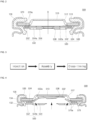
- FIG. 3 is a schematic diagram illustrating the sequence of applying the insulator of FIG. 2 to a cap assembly.
- FIG. 4 is a longitudinal cross-sectional view illustrating a vent-ruptured state of the cap assembly according to FIG. 3 under a high-temperature condition.
- an insulator is applied to the cap assembly 500 by injection molding of the above-described material and then subjecting to welding or thermal fusion.
- the thermal fusion is performed at a temperature of 260 to 270 degrees Celsius, which is higher than the melting point of the insulator 570 made of the above-described material. Therefore, as the contact surface of the insulator 570 in contact with the vent plate 530 and the cap-down 550 is melted, the insulator 570 is assembled to the vent plate 530 and the cap-down 550.
- the materials of the insulator 570 are melted in the ranges of 105 to 110 degrees for PE, 165 to 170 degrees for PP, 74 to 105 degrees for PS, and 60 to 100 degrees for EVA (all temperatures are based on Celsius). Therefore, in a high-temperature operating environment, the insulator 570 may be melted and the insulation function may not be properly maintained. In particular, as shown in FIG. 4 , when the vent plate 530 is broken and the central portion rises toward the cap-up 510, the insulator 570 is relatively pressed.
- the present invention proposes a method of improving thermal characteristics of the insulator 570, which is vulnerable to high temperatures, by applying a cross-linking process to the insulator 570.
- the insulator 570 may be made through injecting into a required shape (injection process) - assembling and fusing into the cap assembly 500 (insertion between vent plate and cap-down and assembly process) - a cross-link process.
- a cross-link process refers to a process of connecting linear molecular chains of a material having linear molecular chains. Materials that have undergone cross-linking have greatly improved mechanical and thermal properties, and exhibit the characteristic of increasing melting points.
- the cross-linking method can be classified into a radiation irradiation method (electron beam cross-linking method), a water cross-linking method, and a chemical cross-linking method.
- the radiation irradiation method is a method of irradiating electron beams and gamma rays to a material to be cross-linked, and is used for cross-linking a thin material such as a film or a thin film because there is a limit to the thickness of cross-linking.
- the water cross-linking method is a method of cross-linking by infiltrating water from the outside through a catalyst after extruding a material by mixing a specific compound such as a silane compound.
- the chemical cross-link method is a method of cross-linking under high temperature and high pressure after extrusion using a compound in which a target material and a cross-linking agent are mixed at 1-3%.
- a material for making the insulator 570 may be cross-linked mainly by a radiation irradiation method or a chemical cross-linking method.
- materials that can be cross-linked by irradiation include polyethylene (PE) and polypropylene (PP).
- the material that can be cross-linked by the chemical cross-linking method may include polyethylene (PE), polypropylene (PP), polystyrene (PS), and ethylene-vinyl acetate copolymer (EVA).
- yet-to-be-crosslinked polypropylene melts at 165 to 170 degrees Celsius, but cross-linked polypropylene has a thermal property that does not melt even at 400 degrees Celsius. Therefore, in the present invention, the insulator 570 is manufactured through a cross-linking process so as to prevent the insulator 570 from melting even in a high temperature environment and maintain power-saving performance.
- insulators made of cross-linked polypropylene do not melt at 260 to 270 degrees Celsius, which is a general heat welding temperature. Accordingly, when the insulator 570 that has undergone the cross-linking process is assembled to the cap assembly 500, the insulator 570 may move or separate between the vent plate 530 and the cap-down 550.
- the insulator 570 may be formed in the order of injection process-assembly process-cross-linking process, as shown in FIG. 3 , rather than in the order of injection process-cross-linking process-assembly process. That is, the shape of the insulator 570 is manufactured through an injection process, and the insulator 570 is inserted between the vent plate 530 and the cap-down 550 in an assembly process, and then fused. The fusion temperature may be higher than the melting point of the material of the insulator 570. Thereafter, the insulator 570 is cross-linked through a cross-linking process. The insulator 570 that has gone through the cross-linking process has been cross-linked after being fused to the cap assembly 500, and thus can maintain insulation performance without melting even in a high temperature environment.
- the insulator 570 of the present invention may maintain insulation performance. As shown in FIG. 4 , in a high-temperature operating environment, the pressure inside the secondary battery 10 may exceed a certain pressure, so that the vent plate 530 may be ruptured. When the notch 532a of the vent plate 530 is ruptured, a ruptured portion may rise toward the cap-up 510 by gas pressure. Here, since the non-ruptured portion of the vent plate 530 is relatively pressed, pressure is applied to the insulator 570. When pressure is applied at high temperatures, general insulators melt more quickly than in a high-temperature environment.
- the insulator 570 of the present invention which has undergone the cross-linking process, does not melt and maintains the shape thereof even when pressure is applied in a high-temperature environment. That is, even after a short circuit occurs, the insulator 570 does not melt and maintains insulation performance.
- the present invention can be applied to various industrial fields including cylindrical secondary batteries, and electronic devices and vehicles equipped therewith.
Landscapes
- Chemical & Material Sciences (AREA)
- Chemical Kinetics & Catalysis (AREA)
- Electrochemistry (AREA)
- General Chemical & Material Sciences (AREA)
- Engineering & Computer Science (AREA)
- Manufacturing & Machinery (AREA)
- Secondary Cells (AREA)
Applications Claiming Priority (2)
| Application Number | Priority Date | Filing Date | Title |
|---|---|---|---|
| KR1020200145314A KR20220059753A (ko) | 2020-11-03 | 2020-11-03 | 원통형 이차전지 |
| PCT/KR2021/014135 WO2022097942A1 (fr) | 2020-11-03 | 2021-10-13 | Batterie secondaire cylindrique |
Publications (1)
| Publication Number | Publication Date |
|---|---|
| EP4243168A1 true EP4243168A1 (fr) | 2023-09-13 |
Family
ID=81457129
Family Applications (1)
| Application Number | Title | Priority Date | Filing Date |
|---|---|---|---|
| EP21889407.9A Pending EP4243168A1 (fr) | 2020-11-03 | 2021-10-13 | Batterie secondaire cylindrique |
Country Status (5)
| Country | Link |
|---|---|
| US (1) | US20230411749A1 (fr) |
| EP (1) | EP4243168A1 (fr) |
| KR (1) | KR20220059753A (fr) |
| CN (1) | CN116636079A (fr) |
| WO (1) | WO2022097942A1 (fr) |
Family Cites Families (5)
| Publication number | Priority date | Publication date | Assignee | Title |
|---|---|---|---|---|
| JP2884372B2 (ja) * | 1990-11-08 | 1999-04-19 | 株式会社フジクラ | ゴム・プラスチック電力ケーブルの接続方法 |
| JP2811378B2 (ja) * | 1991-09-10 | 1998-10-15 | 三菱電線工業株式会社 | ゴム,プラスチック電力ケーブルの接続部および接続方法 |
| JP5829048B2 (ja) * | 2011-05-19 | 2015-12-09 | 住友理工株式会社 | 燃料電池セルアセンブリおよびその製造方法 |
| KR102601641B1 (ko) * | 2016-01-20 | 2023-11-13 | 삼성에스디아이 주식회사 | 이차 전지용 캡 조립체 및 이를 포함하는 이차 전지 |
| KR20180018279A (ko) * | 2016-08-11 | 2018-02-21 | 신흥에스이씨주식회사 | 전기적 단락을 방지하는 캡조립체 및 그를 포함하는 이차전지 |
-
2020
- 2020-11-03 KR KR1020200145314A patent/KR20220059753A/ko active Search and Examination
-
2021
- 2021-10-13 CN CN202180074484.2A patent/CN116636079A/zh active Pending
- 2021-10-13 WO PCT/KR2021/014135 patent/WO2022097942A1/fr active Application Filing
- 2021-10-13 EP EP21889407.9A patent/EP4243168A1/fr active Pending
- 2021-10-13 US US18/250,952 patent/US20230411749A1/en active Pending
Also Published As
| Publication number | Publication date |
|---|---|
| WO2022097942A1 (fr) | 2022-05-12 |
| US20230411749A1 (en) | 2023-12-21 |
| CN116636079A (zh) | 2023-08-22 |
| KR20220059753A (ko) | 2022-05-10 |
Similar Documents
| Publication | Publication Date | Title |
|---|---|---|
| US11569524B2 (en) | Secondary battery and battery pack including the same | |
| US20140315051A1 (en) | Rechargeable battery module | |
| US9425453B2 (en) | Battery module | |
| US11289782B2 (en) | Secondary battery | |
| KR102586879B1 (ko) | 이차 전지 | |
| US10490839B2 (en) | Rechargeable battery | |
| US10340489B2 (en) | Secondary battery | |
| EP3998674A1 (fr) | Batterie secondaire | |
| US20140045009A1 (en) | Secondary battery | |
| US9478833B2 (en) | Secondary battery with a heat shrinkable insulation member | |
| US20220190418A1 (en) | Secondary battery | |
| KR102642157B1 (ko) | 원통형 리튬 이온 이차 전지 | |
| KR20230007111A (ko) | 이차전지 및 이차전지의 제조 방법 | |
| EP4243168A1 (fr) | Batterie secondaire cylindrique | |
| US20240021951A1 (en) | Cylindrical secondary battery | |
| CN115312877A (zh) | 二次电池 | |
| KR100659885B1 (ko) | 리튬이온 이차전지 | |
| KR102670692B1 (ko) | 원통형 이차 전지 | |
| KR102661207B1 (ko) | 이차 전지 | |
| KR102577169B1 (ko) | 원통형 이차 전지 | |
| US20230231284A1 (en) | Secondary battery | |
| US20240113401A1 (en) | Secondary battery | |
| KR20230106935A (ko) | 이차 전지 | |
| KR20230106936A (ko) | 이차 전지 | |
| KR20230115758A (ko) | 이차 전지 |
Legal Events
| Date | Code | Title | Description |
|---|---|---|---|
| STAA | Information on the status of an ep patent application or granted ep patent |
Free format text: STATUS: THE INTERNATIONAL PUBLICATION HAS BEEN MADE |
|
| PUAI | Public reference made under article 153(3) epc to a published international application that has entered the european phase |
Free format text: ORIGINAL CODE: 0009012 |
|
| STAA | Information on the status of an ep patent application or granted ep patent |
Free format text: STATUS: REQUEST FOR EXAMINATION WAS MADE |
|
| 17P | Request for examination filed |
Effective date: 20230502 |
|
| AK | Designated contracting states |
Kind code of ref document: A1 Designated state(s): AL AT BE BG CH CY CZ DE DK EE ES FI FR GB GR HR HU IE IS IT LI LT LU LV MC MK MT NL NO PL PT RO RS SE SI SK SM TR |
|
| DAV | Request for validation of the european patent (deleted) | ||
| DAX | Request for extension of the european patent (deleted) |