EP4243109B1 - Unterlegscheibe für düsenbeschichter und düsenbeschichter zur beschichtung von aktivmaterial auf stromkollektor für sekundärbatterie - Google Patents
Unterlegscheibe für düsenbeschichter und düsenbeschichter zur beschichtung von aktivmaterial auf stromkollektor für sekundärbatterie Download PDFInfo
- Publication number
- EP4243109B1 EP4243109B1 EP22898873.9A EP22898873A EP4243109B1 EP 4243109 B1 EP4243109 B1 EP 4243109B1 EP 22898873 A EP22898873 A EP 22898873A EP 4243109 B1 EP4243109 B1 EP 4243109B1
- Authority
- EP
- European Patent Office
- Prior art keywords
- die coater
- coating liquid
- insulating coating
- electrode slurry
- shim
- Prior art date
- Legal status (The legal status is an assumption and is not a legal conclusion. Google has not performed a legal analysis and makes no representation as to the accuracy of the status listed.)
- Active
Links
Images


Classifications
-
- B—PERFORMING OPERATIONS; TRANSPORTING
- B05—SPRAYING OR ATOMISING IN GENERAL; APPLYING FLUENT MATERIALS TO SURFACES, IN GENERAL
- B05C—APPARATUS FOR APPLYING FLUENT MATERIALS TO SURFACES, IN GENERAL
- B05C5/00—Apparatus in which liquid or other fluent material is projected, poured or allowed to flow on to the surface of the work
- B05C5/02—Apparatus in which liquid or other fluent material is projected, poured or allowed to flow on to the surface of the work the liquid or other fluent material being discharged through an outlet orifice by pressure, e.g. from an outlet device in contact or almost in contact, with the work
- B05C5/0254—Coating heads with slot-shaped outlet
-
- B—PERFORMING OPERATIONS; TRANSPORTING
- B05—SPRAYING OR ATOMISING IN GENERAL; APPLYING FLUENT MATERIALS TO SURFACES, IN GENERAL
- B05C—APPARATUS FOR APPLYING FLUENT MATERIALS TO SURFACES, IN GENERAL
- B05C9/00—Apparatus or plant for applying liquid or other fluent material to surfaces by means not covered by any preceding group, or in which the means of applying the liquid or other fluent material is not important
- B05C9/06—Apparatus or plant for applying liquid or other fluent material to surfaces by means not covered by any preceding group, or in which the means of applying the liquid or other fluent material is not important for applying two different liquids or other fluent materials, or the same liquid or other fluent material twice, to the same side of the work
-
- H—ELECTRICITY
- H01—ELECTRIC ELEMENTS
- H01M—PROCESSES OR MEANS, e.g. BATTERIES, FOR THE DIRECT CONVERSION OF CHEMICAL ENERGY INTO ELECTRICAL ENERGY
- H01M10/00—Secondary cells; Manufacture thereof
- H01M10/42—Methods or arrangements for servicing or maintenance of secondary cells or secondary half-cells
- H01M10/4235—Safety or regulating additives or arrangements in electrodes, separators or electrolyte
-
- H—ELECTRICITY
- H01—ELECTRIC ELEMENTS
- H01M—PROCESSES OR MEANS, e.g. BATTERIES, FOR THE DIRECT CONVERSION OF CHEMICAL ENERGY INTO ELECTRICAL ENERGY
- H01M4/00—Electrodes
- H01M4/02—Electrodes composed of, or comprising, active material
- H01M4/04—Processes of manufacture in general
- H01M4/0402—Methods of deposition of the material
- H01M4/0404—Methods of deposition of the material by coating on electrode collectors
-
- H—ELECTRICITY
- H01—ELECTRIC ELEMENTS
- H01M—PROCESSES OR MEANS, e.g. BATTERIES, FOR THE DIRECT CONVERSION OF CHEMICAL ENERGY INTO ELECTRICAL ENERGY
- H01M4/00—Electrodes
- H01M4/02—Electrodes composed of, or comprising, active material
- H01M4/04—Processes of manufacture in general
- H01M4/0402—Methods of deposition of the material
- H01M4/0409—Methods of deposition of the material by a doctor blade method, slip-casting or roller coating
-
- Y—GENERAL TAGGING OF NEW TECHNOLOGICAL DEVELOPMENTS; GENERAL TAGGING OF CROSS-SECTIONAL TECHNOLOGIES SPANNING OVER SEVERAL SECTIONS OF THE IPC; TECHNICAL SUBJECTS COVERED BY FORMER USPC CROSS-REFERENCE ART COLLECTIONS [XRACs] AND DIGESTS
- Y02—TECHNOLOGIES OR APPLICATIONS FOR MITIGATION OR ADAPTATION AGAINST CLIMATE CHANGE
- Y02E—REDUCTION OF GREENHOUSE GAS [GHG] EMISSIONS, RELATED TO ENERGY GENERATION, TRANSMISSION OR DISTRIBUTION
- Y02E60/00—Enabling technologies; Technologies with a potential or indirect contribution to GHG emissions mitigation
- Y02E60/10—Energy storage using batteries
Definitions
- the present invention relates to a die coater shim and die coater for effectively and simultaneously coating an electrode slurry and an insulating coating liquid on a current collector for a secondary battery.
- lithium secondary batteries are widely used as an energy source of various electronic products as well as various mobile devices due to having high energy density and high operating voltage and being excellent in terms of preservation and lifespan.
- An electrode in which an active material layer and an insulating layer are formed on a surface of a current collector is used in a lithium secondary battery or the like.
- Such an electrode is manufactured by applying both an electrode slurry including an active material or the like and an insulating coating liquid including an insulating material or the like on a surface of a current collector using a coating apparatus such as a die coater so that the electrode slurry and the insulating coating liquid overlap with a portion of a corner of an electrode mixture layer and drying the electrode slurry and the insulating coating liquid.
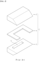
- FIG. 1 illustrates a conventional die coater 1 for applying an electrode slurry.
- the die coater 1 includes an upper block 2 and a lower block 3, a die coater shim 4 is interposed between the upper block 2 and the lower block 3, and the upper block 2, the lower block 3, and the die coater shim 4 are fastened using a plurality of bolt members and coupled to each other.
- a manifold 5 configured to accommodate a certain volume of electrode slurry is provided in the lower block 3, and the manifold 5 communicates with an external electrode slurry supply (not illustrated).
- the die coater shim simultaneously serves to form a slit of a suitable height between the upper block and the lower block, limit a flowing direction of an electrode slurry so that the electrode slurry is discharged toward the slit, and perform sealing so that the electrode slurry does not leak to portions other than the slit.
- the die coater shim has guides protruding from both ends thereof in a width direction, and a distance between the guides determines a width at which the electrode slurry is applied on a current collector.
- An insulating coating liquid is applied on both corners in the width direction of the electrode slurry applied on the current collector.
- applying the insulating coating liquid is performed as an additional process using a separate apparatus after applying the electrode slurry on the current collector. Applying the electrode slurry and the insulating coating liquid on the current collector through separate processes in this way is undesirable in terms of production efficiency.
- An object of the present invention is to provide a die coater shim and die coater for simultaneously and effectively coating an electrode slurry and an insulating coating liquid on a current collector for a secondary battery.
- the die coater shim includes: a base configured to extend in a width direction; first and second guides configured to protrude and extend from both ends of the base; an electrode slurry slit including a step portion configured to extend from the base in the width direction between the first and second guides, wherein a thickness of the step portion is smaller than a thickness of the base, and a stepped space that the step portion forms relative to one surface of the base forms an electrode slurry discharge path; and first and second insulating coating liquid slits including a groove formed on a surface of each of the first and second guides that corresponds to the other surface of the base, wherein one end of the groove forms an insulating coating liquid discharge path.
- the step portion may extend to a partial area in the width direction between the first and second guides.
- the one end of the groove that forms an outlet of the first and second insulating coating liquid slits may extend to protruding end portions of the first and second guides.
- the one end of the groove may be spaced apart from inner corners of the first and second guides that face each other.
- the die coater shim may further include a third guide positioned between the first and second guides and configured to protrude and extend from the base, the step portion may be formed of a first step portion disposed between the first and third guides and a second step portion disposed between the third and second guides, the electrode slurry slit may be formed of a first electrode slurry slit configured to form a first electrode slurry discharge path using the first step portion and a second electrode slurry slit configured to form a second electrode slurry discharge path using the second step portion, and the die coater shim may further include third and fourth insulating coating liquid slits including a pair of grooves formed on a surface of the third guide that corresponds to the other surface of the base, wherein one end of each of the pair of grooves forms an insulating coating liquid discharge path.
- outlets of the third and fourth insulating coating liquid slits may face the first and second guides.
- widths of the first and second step portions may be equal to each other.
- an aspect of the present invention provides a die coater including: an upper block in which an insulating coating liquid inlet is provided; a lower block coupled to the upper block and in which a manifold configured to accommodate an electrode slurry is provided; and a die coater shim interposed between the upper block and the lower block to form a slit and configured to simultaneously discharge an insulating coating liquid and the electrode slurry through the slit, wherein the die coater shim has an electrode slurry discharge path formed on one surface and an insulating coating liquid discharge path formed on the other surface opposite to the one surface, and the electrode slurry discharge path and the insulating coating liquid discharge path are physically separated from each other on the die coater shim.
- the die coater shim may include: a base configured to extend in a width direction; first and second guides configured to protrude and extend from both ends of the base; an electrode slurry slit including a step portion configured to extend from the base in the width direction between the first and second guides, wherein a thickness of the step portion is smaller than a thickness of the base, and a stepped space that the step portion forms relative to one surface of the base forms an electrode slurry discharge path; and first and second insulating coating liquid slits including a groove formed on a surface of each of the first and second guides that corresponds to the other surface of the base, wherein one end of the groove forms an insulating coating liquid discharge path.
- the step portion may extend to a partial area in the width direction between the first and second guides.
- a boundary between the base and the step portion may coincide with a rear end of the manifold provided in the lower block, and an end portion of the step portion may coincide with a front end of the manifold or protrude from the front end of the manifold.
- the end portion of the step portion may protrude 10 mm or less from the front end of the manifold.
- the one end of the groove that forms an outlet of the first and second insulating coating liquid slits may extend to protruding end portions of the first and second guides.
- the one end of the groove may be spaced apart from inner corners of the first and second guides that face each other.
- a die coater shim of the present invention is configured to simultaneously discharge an insulating coating liquid and an electrode slurry, and in particular, an electrode slurry discharge path and an insulating coating liquid discharge path are physically separated from each other on the die coater shim.
- the die coater shim of the present invention effectively prevents the electrode slurry and the insulating coating liquid from being mixed with each other even when the electrode slurry and/or the insulating coating liquid leak inside a die coater.
- the present invention allows an electrode slurry and an insulating coating liquid to be simultaneously and effectively coated on a current collector for a secondary battery.
- a part such as a layer, a film, an area, or a plate when a part such as a layer, a film, an area, or a plate is described as being “on” another part, this includes not only a case where the part is “directly on” the other part, but also a case where still another part is present therebetween.
- a part such as a layer, a film, an area, or a plate when a part such as a layer, a film, an area, or a plate is described as being “under” another part, this includes not only a case where the part is “directly under” the other part, but also a case where still another part is present therebetween.
- being disposed “on” may include not only being disposed on an upper portion, but also being disposed on a lower portion.
- a die coater shim includes: a base configured to extend in a width direction; first and second guides configured to protrude and extend from both ends of the base; an electrode slurry slit including a step portion configured to extend from the base in the width direction between the first and second guides, wherein a thickness of the step portion is smaller than a thickness of the base, and a stepped space that the step portion forms relative to one surface of the base forms an electrode slurry discharge path; and first and second insulating coating liquid slits including a groove formed on a surface of each of the first and second guides that corresponds to the other surface of the base, wherein one end of the groove forms an insulating coating liquid discharge path.
- the die coater shim according to the present invention has the electrode slurry discharge path formed on one surface and the insulating coating liquid discharge path formed on the other surface opposite to the one surface, the die coater shim can simultaneously apply an electrode slurry and an insulating coating liquid on a current collector. Further, since the electrode slurry discharge path and the insulating coating liquid discharge path are physically separated from each other on the die coater shim, even when any one solution leaks in a die coater, the two solutions are prevented from being mixed with each other.
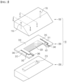
- FIG. 2 is a view illustrating a structure of a die coater 10 including a die coater shim 300 according to an embodiment of the present invention.
- the overall configuration of the die coater 10 and the die coater shim 300 will be described in detail below with reference to FIG. 2 .
- the die coater 10 includes an upper block 100 and a lower block 200, and the die coater shim 300 is interposed between the upper block 100 and the lower block 200.
- the upper block 100 and the lower block 200 are parts constituting a body of the die coater 10, an insulating coating liquid inlet 110 is provided in the upper block 100, and a manifold 210 configured to accommodate an electrode slurry supplied from an outside is provided in the lower block 200.
- the die coater shim 300 is interposed between the upper block 100 and the lower block 200 to form a slit having a height suitable for discharging the electrode slurry. Also, the die coater shim 300 serves to limit a flowing direction of the electrode slurry so that the electrode slurry is discharged toward the slit without flowing backward and serves to perform sealing so that the electrode slurry does not leak to portions other than the slit.
- the die coater shim 300 has guides 311 and 312 protruding from both ends thereof in a width direction, and a distance between the guides 311 and 312 determines a width at which the electrode slurry is applied on a current collector.
- the die coater shim 300 of the present embodiment is the same as the related art in that a slit for discharging an electrode slurry is formed therein but is different from the related art in that the die coater shim 300 of the present embodiment is configured to simultaneously discharge an insulating coating liquid and an electrode slurry.
- the die coater shim 300 of the present embodiment has an electrode slurry discharge path formed on the bottom surface of the base and an insulating coating liquid discharge path formed on the top surface of the base, and the electrode slurry discharge path and the insulating coating liquid discharge path are physically separated from each other on the die coater shim 300. Since the electrode slurry discharge path and the insulating coating liquid discharge path are physically separated in this way, even when any one liquid (the electrode slurry and/or the insulating coating liquid) leaks inside the die coater 10, the one liquid is effectively prevented from being mixed with the other liquid.
- FIG. 3 shows cross-sectional views taken along lines "A-A" and "B-B" of FIG. 2 in a state in which the die coater 10 of FIG. 2 is assembled
- FIG. 4 is a front view of the die coater 10 of FIG. 2 in the state in which the die coater 10 is assembled
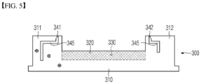
- FIG. 5 is a plan view illustrating a specific structure of the die coater shim 300 illustrated in FIG. 2 .
- the die coater shim 300 includes a base 310 configured to extend in the width direction and the first and second guides 311 and 312 configured to protrude and extend from both ends of the base 310, and such a structure corresponds to the related art shown in FIG. 1 .
- the die coater shim 300 of the present embodiment includes a step portion 320 configured to extend from the base 310 in the width direction between the first and second guides 311 and 312.
- a thickness of the step portion 320 is smaller than a thickness of the base 310, and accordingly, the step portion 320 forms a stepped space relative to one surface of the base 310 (a surface thereof facing the lower block).
- the space that the step portion 320 forms communicates with the lower block 200 in which the manifold 210 is formed.
- the step portion 320 forms an electrode slurry slit 330 that forms a discharge path for the electrode slurry accommodated in the manifold 210.
- first and second guides 311 and 312 each include a groove 345 formed in a surface corresponding to the other surface of the base 310 (a surface thereof facing the upper block), and as one end of each groove 345 forms an insulating coating liquid discharge path, first and second insulating coating liquid slits 341 and 342 are provided on the first and second guides 311 and 312. Referring to the "B-B" section of FIG. 3 and the front view of FIG. 4 , the first and second insulating coating liquid slits 341 and 342 are formed toward the upper block 100, and accordingly, the electrode slurry slit 330 and the first and second insulating coating liquid slits 341 and 342 are physically separated from each other.
- upper and lower surfaces of the first and second guides 311 and 312 around the first and second insulating coating liquid slits 341 and 342 are in close contact with the upper block 100 and the lower block 200, and thus, along with the upper block 100, the first and second insulating coating liquid slits 341 and 342 form independent insulating coating liquid discharge paths isolated from surroundings thereof.
- the electrode slurry slit 330 is formed by the space that the step portion 320 between the first and second guides 311 and 312 forms, and accordingly, the electrode slurry discharge path is separated from the first and second guides 311 and 312 due to the step portion 320 and the lower block 200.
- the first and second insulating coating liquid slits 341 and 342 are disposed toward the upper block 100, and the electrode slurry discharge path is disposed toward the lower block 200 and spatially separated, even when any one solution (the electrode slurry and/or the insulating coating liquid) leaks inside the die coater 10, mixing of the two solutions hardly occurs.
- the step portion 320 may extend to a partial area in the width direction between the first and second guides 311 and 312. It is necessary for the step portion 320 to have a certain length because the step portion 320 serves to effectively separate the first and second guides 311 and 312 from the manifold 210 of the lower block 200. However, the length of the step portion 320 being too long may adversely affect a flow profile in the electrode slurry discharge path. For example, air bubbles may be present due to a vortex when the electrode slurry is discharged. Thus, there is a need to appropriately design the length of the step portion 320.
- a boundary between the base 310 and the step portion 320 may coincide with a rear end (a left side end in the "A-A" section of FIG. 3 ) of the manifold 210 provided in the lower block 200 to ensure tight sealing of the manifold 210, and an extending end portion of the step portion 320 may at least coincide with a front end of the manifold 210 or protrude from the front end of the manifold 210.
- the extending end portion of the step portion 320 may protrude 10 mm or less from the front end of the manifold 210.
- the one end of the groove 345 that forms an outlet of the first and second insulating coating liquid slits 341 and 342 may extend to protruding end portions of the first and second guides 311 and 312. Such a configuration is shown in the "B-B" section of FIG. 3 . Accordingly, the outlet of the first and second insulating coating liquid slits 341 and 342 is positioned at a sharp end portion of the die coater 10.
- the one end of the groove 345 may be spaced apart from inner corners of the first and second guides 311 and 312 that face each other.
- a distance at which the one end of the groove 345 that forms the outlet of the first and second insulating coating liquid slits 341 and 342 is spaced apart from the inner corners of the first and second guides 311 and 312 corresponds to a distance at which the one end is spaced apart from both ends of an electrode slurry discharge width defined by the inner corners of the first and second guides 311 and 312. This is to, when an electrode slurry and an insulating coating liquid are simultaneously discharged, prevent the insulating coating liquid, which has slight fluidity, from being immediately mixed with a corner of the discharged electrode slurry.
- a second embodiment of the present invention is an embodiment suitable for a case in which an electrode slurry and an insulating coating liquid are applied in two or more rows on a current collector supplied in the form of a coil and then slitting is performed.
- the second embodiment corresponds to an embodiment suitable for simultaneously applying an active material coating, which is formed of an "insulating coating liquid-electrode slurry-insulating coating liquid" structure, in two or more rows on a current collector.
- the die coater shim 300 there is no significant change in the configuration of the upper block 100 and the lower block 200 constituting the die coater 10, and a main difference is in the die coater shim 300.
- additional insulating coating liquid slits 343 and 344 are present in the die coater shim 300 of the second embodiment, an additional insulating coating liquid inlet 110 corresponding thereto may be required in the upper block 100.
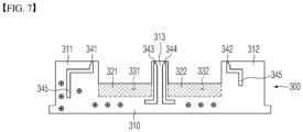
- the configuration of the die coater shim 300 according to the second embodiment is shown in FIG. 7 , and the second embodiment will be described focusing on the differences from the first embodiment described above.
- the die coater shim 300 of the second embodiment further includes a third guide 313 positioned between the first and second guides 311 and 312 and configured to protrude and extend from an intermediate portion of the base 310.
- a pair of grooves 345 are formed on a surface of the third guide 313 that corresponds to the other surface of the base 310 (the surface thereof facing the upper block), and one ends of the pair of grooves 345 constitute third and fourth insulating coating liquid slits 343 and 344 that form additional insulating coating liquid discharge paths.
- an active material may be simultaneously applied in two rows on a current collector in order to be suitable for slitting.
- widths of the first and second step portions 321 and 322 may be made equal to each other.
- the width of the insulating coating liquid is almost constant regardless of the width of the electrode slurry, there is no need to significantly change the configuration of the third and fourth insulating coating liquid slits 343 and 344.
- the present invention is suitable for application to a die coater for simultaneously coating an electrode slurry and an insulating coating liquid on a current collector for a secondary battery.
Landscapes
- Engineering & Computer Science (AREA)
- Manufacturing & Machinery (AREA)
- Chemical & Material Sciences (AREA)
- Chemical Kinetics & Catalysis (AREA)
- Electrochemistry (AREA)
- General Chemical & Material Sciences (AREA)
- Coating Apparatus (AREA)
- Battery Electrode And Active Subsutance (AREA)
Claims (13)
- Düsenbeschichtungseinheitsabstandselement (300) zum simultanen Aufbringen einer Elektrodensuspension und einer Isolierungsbeschichtungsflüssigkeit an einem Stromkollektor, wobei das Düsenbeschichtungseinheitsabstandselement (300) umfasst:eine Basis (310), welche dazu eingerichtet ist, sich in einer Breitenrichtung zu erstrecken;eine erste und eine zweite Führung (311, 312), welche an jedem Ende der Basis (310) in der Breitenrichtung angeordnet sind, wobei die erste und die zweite Führung (311, 312) vorstehen und sich erstrecken von der Basis (310) in einer Richtung, welche orthogonal zu der Breitenrichtung ist;dadurch gekennzeichnet, dass ein erster Elektrodensuspension-Schlitz (331), welcher einen ersten Stufenabschnitt (321) umfasst, zwischen der ersten und der zweiten Führung (311, 312) in der Breitenrichtung angeordnet ist, wobei eine Dicke des ersten Stufenabschnitts (321) kleiner als eine Dicke der Basis (310) ist, wobei die Dicke des ersten Stufenabschnitts (321) einen ersten gestuften Raum relativ zu einer ersten Fläche der Basis (310) bildet, wobei der erste gestufte Raum einen Elektrodensuspensionsabgabeweg bildet; und dassein erster und ein zweiter Isolierungsbeschichtungsflüssigkeit-Schlitz (341, 342), welche eine Nut (345) umfassen, an einer Fläche von jeder der ersten und der zweiten Führung (311, 312) gebildet ist, welche an einer zweiten Fläche der Basis (310) angeordnet sind, wobei ein Ende von jeder der Nuten (345) einen Isolierungsbeschichtungsflüssigkeitsabgabeweg bildet.
- Düsenbeschichtungseinheitsabstandselement (300) nach Anspruch 1, wobei sich ein Stufenabschnitt (320) zu einem Teilbereich in der Breitenrichtung zwischen der ersten und der zweiten Führung (311, 312) erstreckt, wobei die erste und die zweite Führung (311, 312) von dem Teilbereich in der Richtung, welche orthogonal zu der Breitenrichtung ist, vorstehen und sich erstrecken.
- Düsenbeschichtungseinheitsabstandselement (300) nach Anspruch 1, wobei das eine Ende jeder der Nuten (345) einen Auslass des ersten und des zweiten Isolierungsbeschichtungsflüssigkeit-Schlitzes (341, 342) gebildet, wobei sich das eine Ende jeder der Nuten (345) zu einem vorstehenden Endabschnitt jeder der ersten und der zweiten Führung (311, 312) erstreckt.
- Düsenbeschichtungseinheitsabstandselement (300) nach Anspruch 3, wobei das eine Ende jeder der Nuten (345) in der Breitenrichtung von inneren Ecken der ersten und der zweiten Führung (311, 312) weiter beabstandet ist.
- Düsenbeschichtungseinheitsabstandselement (300) nach Anspruch 1, ferner umfassend:eine dritte Führung (313), welche zwischen der ersten und der zweiten Führung (311, 312) positioniert ist, wobei die dritte Führung (313) von der Basis (310) in der Richtung, welche orthogonal zu der Breitenrichtung ist, vorsteht und sich erstreckt, undeinen dritten und einen vierten Isolierungsbeschichtungsflüssigkeit-Schlitz (343, 344), welche ein Paar Nuten (345) umfassen, welche an einer Fläche der dritten Führung (313) gebildet sind, wobei ein Ende von jedem des Paars von Nuten (345) einen Isolierungsbeschichtungsflüssigkeitsabgabeweg bildet,wobei der Stufenabschnitt (320) einen ersten Stufenabschnitt (321) und einen zweiten Stufenabschnitt (322) umfasst, wobei der erste Stufenabschnitt (321) zwischen der ersten und der dritten Führung (311, 313) angeordnet ist und der zweite Stufenabschnitt (322) zwischen der dritten und der zweiten Führung (313, 312) angeordnet ist,wobei der Elektrodensuspension-Schlitz (330) den ersten Elektrodensuspension-Schlitz (331) und einen zweiten Elektrodensuspension-Schlitz (332) umfasst, wobei der zweite Elektrodensuspension-Schlitz (332) einen zweiten Stufenabschnitt (322) umfasst, wobei eine zweite Dicke des zweiten Stufenabschnitts (322) kleiner als die Dicke der Basis (310) ist, wobei die Dicke des zweiten Stufenabschnitts (322) einen zweiten gestuften Raum relativ zu der ersten Fläche der Basis (310) bildet, wobei der zweite gestufte Raum einen zweiten Elektrodensuspensionsabgabeweg bildet.
- Düsenbeschichtungseinheitsabstandselement (300) nach Anspruch 5, wobei ein Auslass des dritten Isolierungsbeschichtungsflüssigkeit-Schlitz (343) der ersten Führung (311) zugewandt ist und ein Auslass des vierten Isolierungsbeschichtungsflüssigkeit der zweiten Führung (312) zugewandt ist.
- Düsenbeschichtungseinheitsabstandselement (300) nach Anspruch 5, wobei eine Breite von jedem des ersten und des zweiten Stufenabschnitts (321, 322) gleich sind.
- Düsenbeschichtungseinheit (10), umfassend:einen oberen Block (100), welcher einen Isolierungsbeschichtungsflüssigkeitseinlass (110) aufweist;einen unteren Block (200), welcher mit dem oberen Block (100) gekoppelt ist, wobei der untere Block (200) einen Sammler (210) umfasst, welcher dazu eingerichtet ist, eine Elektrodensuspension aufzunehmen; undein Düsenbeschichtungseinheitsabstandselement (300), welches zwischen dem oberen Block (100) und dem unteren Block (200) eingefügt ist, um einen Schlitz zu bilden, wobei die Düsenbeschichtungseinheit (10) dazu eingerichtet ist, eine Isolierungsbeschichtungsflüssigkeit und die Elektrodensuspension durch den Schlitz simultan abzugeben,wobei das Düsenbeschichtungseinheitsabstandselement (300) einen Elektrodensuspensionsabgabeweg, welcher an einer ersten Fläche der Basis (310) gebildet ist, und einen Isolierungsbeschichtungsflüssigkeitsabgabeweg aufweist, welcher an einer zweiten Fläche der Basis (310) gebildet ist,wobei der Elektrodensuspensionsabgabeweg und der Isolierungsbeschichtungsflüssigkeitsabgabeweg an dem Düsenbeschichtungseinheitsabstandselement (300) physisch voneinander getrennt sind,dadurch gekennzeichnet, dass das Düsenbeschichtungseinheitsabstandselement (300) ist, wie in Anspruch 1 definiert.
- Düsenbeschichtungseinheit (10) nach Anspruch 8, wobei sich der Stufenabschnitt (320) zu einem Teilbereich in der Breitenrichtung zwischen der ersten und der zweiten Führung (311, 312) erstreckt, wobei die erste und die zweite Führung (311, 312) von dem Teilbereich in der Richtung, welche orthogonal zu der Breitenrichtung ist, vorstehen und sich erstrecken.
- Düsenbeschichtungseinheit (10) nach Anspruch 9, wobei:eine Grenze zwischen der Basis (310) und dem Stufenabschnitt (320) mit einem hinteren Ende des Sammlers (210) zusammenfällt, welcher in dem unteren Block (200) bereitgestellt ist, wobei das hintere Ende des Sammlers (210) benachbart zu der Basis (310) der Düsenbeschichtungseinheit (10) angeordnet ist; undein Endabschnitt des Stufenabschnitts (320) mit einem vorderen Ende des Sammlers (210) zusammenfällt oder von dem vorderen Ende des Sammlers (210) vorsteht, wobei das vordere Ende des Sammlers (210) weiter weg von der Basis (310) der Düsenbeschichtungseinheit (10) als von dem hinteren Ende des Sammlers (210) angeordnet ist.
- Düsenbeschichtungseinheit (10) nach Anspruch 10, wobei der Endabschnitt des Stufenabschnitts (320) 10 mm oder weniger von dem vorderen Ende des Sammlers (210) vorsteht.
- Düsenbeschichtungseinheit (10) nach Anspruch 8, wobei das eine Ende jeder der Nuten (345) einen Auslass des ersten und des zweiten Isolierungsbeschichtungsflüssigkeit-Schlitzes (341, 342) bildet, wobei das eine Ende jeder der Nuten (345) sich zu einem vorstehenden Endabschnitt jeder der ersten und der zweiten Führung (311, 312) erstreckt.
- Düsenbeschichtungseinheit (10) nach Anspruch 12, wobei das eine Ende jeder der Nuten (345) in der Breitenrichtung von inneren Ecken der ersten und der zweiten Führung (311, 312) weiter beabstandet ist.
Applications Claiming Priority (2)
| Application Number | Priority Date | Filing Date | Title |
|---|---|---|---|
| KR1020210167134A KR102872643B1 (ko) | 2021-11-29 | 2021-11-29 | 이차전지용 집전체에 활물질을 코팅하기 위한 다이 코터용 심 및 다이 코터 |
| PCT/KR2022/016788 WO2023096191A1 (ko) | 2021-11-29 | 2022-10-31 | 이차전지용 집전체에 활물질을 코팅하기 위한 다이 코터용 심 및 다이 코터 |
Publications (3)
| Publication Number | Publication Date |
|---|---|
| EP4243109A1 EP4243109A1 (de) | 2023-09-13 |
| EP4243109A4 EP4243109A4 (de) | 2024-07-17 |
| EP4243109B1 true EP4243109B1 (de) | 2025-06-11 |
Family
ID=86539826
Family Applications (1)
| Application Number | Title | Priority Date | Filing Date |
|---|---|---|---|
| EP22898873.9A Active EP4243109B1 (de) | 2021-11-29 | 2022-10-31 | Unterlegscheibe für düsenbeschichter und düsenbeschichter zur beschichtung von aktivmaterial auf stromkollektor für sekundärbatterie |
Country Status (9)
| Country | Link |
|---|---|
| US (1) | US20240024911A1 (de) |
| EP (1) | EP4243109B1 (de) |
| JP (1) | JP7596017B2 (de) |
| KR (1) | KR102872643B1 (de) |
| CN (1) | CN116569382A (de) |
| ES (1) | ES3034927T3 (de) |
| HU (1) | HUE072054T2 (de) |
| PL (1) | PL4243109T3 (de) |
| WO (1) | WO2023096191A1 (de) |
Families Citing this family (7)
| Publication number | Priority date | Publication date | Assignee | Title |
|---|---|---|---|---|
| KR20220059744A (ko) * | 2020-11-03 | 2022-05-10 | 주식회사 엘지에너지솔루션 | 다이 코터용 심, 이를 포함하는 다이 코터 및 이를 이용하여 제조된 양극을 포함하는 리튬 이차전지 |
| KR20250140896A (ko) * | 2024-03-19 | 2025-09-26 | 주식회사 엘지에너지솔루션 | 코팅 장치 |
| KR20250175511A (ko) | 2024-06-10 | 2025-12-17 | 주식회사 엘지에너지솔루션 | 코팅 장치 |
| KR20260000681A (ko) * | 2024-06-26 | 2026-01-05 | 주식회사 엘지에너지솔루션 | 다이 코터 |
| KR20260001377A (ko) * | 2024-06-27 | 2026-01-05 | 삼성에스디아이 주식회사 | 슬롯 다이 코터 |
| KR20260038097A (ko) * | 2024-09-11 | 2026-03-18 | 삼성에스디아이 주식회사 | 이차전지 전극판 코팅 장치 및 방법과 이에 이용되는 슬롯다이 |
| JP2026064272A (ja) * | 2024-10-02 | 2026-04-14 | 東レエンジニアリング株式会社 | 塗布装置 |
Family Cites Families (19)
| Publication number | Priority date | Publication date | Assignee | Title |
|---|---|---|---|---|
| EP2533964B1 (de) * | 2010-02-08 | 2017-01-11 | 3M Innovative Properties Company | Koextrusionsdüse und verfahren zum herstellen eines extrudierten artikels unter verwendung derselben |
| JP5542523B2 (ja) * | 2010-05-18 | 2014-07-09 | 株式会社ヒラノテクシード | スリットダイ |
| KR101308251B1 (ko) * | 2011-03-18 | 2013-09-13 | 삼성에스디아이 주식회사 | 슬롯 다이 |
| KR102056479B1 (ko) * | 2012-12-12 | 2019-12-16 | 광주과학기술원 | 멀티 코팅이 가능한 슬롯다이 |
| JP6096077B2 (ja) * | 2013-07-25 | 2017-03-15 | オートモーティブエナジーサプライ株式会社 | 塗工ヘッド及びこれを用いた塗工装置 |
| KR101762813B1 (ko) * | 2015-01-14 | 2017-07-28 | 주식회사 엘지화학 | 두개의 심을 포함하는 슬롯 다이 및 이를 포함하는 코팅 장치 |
| KR101737683B1 (ko) * | 2015-01-16 | 2017-05-29 | 주식회사 엘지화학 | 다이 코터용 유량조절부재 및 이를 포함하는 코팅 장치 |
| KR102134587B1 (ko) * | 2016-02-12 | 2020-07-16 | 주식회사 엘지화학 | 이차전지용 전극을 구성하는 이종 소재의 동시 코팅이 가능한 전극 코팅 장치 |
| CN110198792B (zh) * | 2017-02-03 | 2021-10-26 | 日本汽车能源株式会社 | 涂敷模具、涂敷装置、涂敷方法以及二次电池的制造方法 |
| CN208173722U (zh) * | 2017-08-24 | 2018-11-30 | 日立汽车系统株式会社 | 二次电池 |
| JP7155881B2 (ja) * | 2018-10-31 | 2022-10-19 | トヨタ自動車株式会社 | 電極板、これを用いた電池、電極板の製造方法、これを用いた電池の製造方法、ダイヘッド |
| TWM577762U (zh) * | 2018-12-07 | 2019-05-11 | 財團法人工業技術研究院 | Clip and slot coater applying the same |
| JP7124695B2 (ja) * | 2018-12-27 | 2022-08-24 | トヨタ自動車株式会社 | 正極の製造装置 |
| CN209646879U (zh) * | 2019-01-23 | 2019-11-19 | 欣旺达电子股份有限公司 | 涂布垫片 |
| KR102035826B1 (ko) * | 2019-05-31 | 2019-10-24 | 씨아이에스(주) | 다열 동시 코팅 슬롯다이 |
| JP7368125B2 (ja) * | 2019-07-05 | 2023-10-24 | 株式会社Aescジャパン | 塗工装置及び電池用電極の製造方法 |
| KR20210083512A (ko) | 2019-12-27 | 2021-07-07 | 주식회사 엘지에너지솔루션 | 코팅 균일성이 우수한 전극 슬러리 토출용 코팅 심 및 이를 포함하는 코팅 다이 |
| JP2021120148A (ja) * | 2020-01-30 | 2021-08-19 | トヨタ自動車株式会社 | ダイ塗工装置 |
| CN113510044B (zh) * | 2021-04-30 | 2022-10-04 | 西安瑟福能源科技有限公司 | 一种小面密度狭缝式涂布垫片 |
-
2021
- 2021-11-29 KR KR1020210167134A patent/KR102872643B1/ko active Active
-
2022
- 2022-10-31 EP EP22898873.9A patent/EP4243109B1/de active Active
- 2022-10-31 HU HUE22898873A patent/HUE072054T2/hu unknown
- 2022-10-31 ES ES22898873T patent/ES3034927T3/es active Active
- 2022-10-31 JP JP2023535042A patent/JP7596017B2/ja active Active
- 2022-10-31 WO PCT/KR2022/016788 patent/WO2023096191A1/ko not_active Ceased
- 2022-10-31 CN CN202280007894.XA patent/CN116569382A/zh active Pending
- 2022-10-31 US US18/266,330 patent/US20240024911A1/en active Pending
- 2022-10-31 PL PL22898873.9T patent/PL4243109T3/pl unknown
Also Published As
| Publication number | Publication date |
|---|---|
| EP4243109A4 (de) | 2024-07-17 |
| CN116569382A (zh) | 2023-08-08 |
| PL4243109T3 (pl) | 2025-08-18 |
| KR20230079911A (ko) | 2023-06-07 |
| US20240024911A1 (en) | 2024-01-25 |
| HUE072054T2 (hu) | 2025-10-28 |
| KR102872643B1 (ko) | 2025-10-16 |
| JP7596017B2 (ja) | 2024-12-09 |
| EP4243109A1 (de) | 2023-09-13 |
| JP2024501439A (ja) | 2024-01-12 |
| WO2023096191A1 (ko) | 2023-06-01 |
| ES3034927T3 (en) | 2025-08-26 |
Similar Documents
| Publication | Publication Date | Title |
|---|---|---|
| EP4243109B1 (de) | Unterlegscheibe für düsenbeschichter und düsenbeschichter zur beschichtung von aktivmaterial auf stromkollektor für sekundärbatterie | |
| EP4289518A1 (de) | Düsenbeschichter zur beschichtung eines sekundärbatteriestromabnehmers mit aktivem material | |
| US11850627B2 (en) | Coating die, coating device, coating method, and method for manufacturing secondary cell | |
| EP4321264B1 (de) | Zur mehrschichtigen beschichtung von aktiven materialien fähige düsenbeschichtungsvorrichtung | |
| EP4353365B1 (de) | Düsenbeschichter zur beschichtung von aktivmaterial eines sekundärbatteriestromkollektors | |
| US20240286163A1 (en) | Coating die and coating device of battery electrode plate | |
| KR20220148284A (ko) | 엔드 커버 어셈블리, 배터리 셀, 배터리 팩 및 장치 | |
| US20250050372A1 (en) | Die Coater for Coating Active Material of Secondary Battery Current Collector | |
| US20230079707A1 (en) | Slot Die Coater | |
| KR102874374B1 (ko) | 슬롯 다이 코터 | |
| EP4534210B1 (de) | Düsenbeschichter zur beschichtung von elektrodenschlämmen und isolierender flüssigkeit | |
| KR20250085633A (ko) | 다이 코터, 이를 포함하는 코팅 설비 및 이를 이용한 전극의 코팅 방법 | |
| JP7664497B1 (ja) | スロットダイコーター | |
| JP2026508470A (ja) | 分割マニホールドを備えたスロットダイ | |
| CN119907719A (zh) | 间隔垫片和槽模涂覆机 | |
| CN121222623A (zh) | 狭缝模具涂布机 | |
| CN120712149A (zh) | 狭缝模具涂布机 | |
| KR20240054620A (ko) | 이차전지 |
Legal Events
| Date | Code | Title | Description |
|---|---|---|---|
| STAA | Information on the status of an ep patent application or granted ep patent |
Free format text: STATUS: THE INTERNATIONAL PUBLICATION HAS BEEN MADE |
|
| PUAI | Public reference made under article 153(3) epc to a published international application that has entered the european phase |
Free format text: ORIGINAL CODE: 0009012 |
|
| STAA | Information on the status of an ep patent application or granted ep patent |
Free format text: STATUS: REQUEST FOR EXAMINATION WAS MADE |
|
| 17P | Request for examination filed |
Effective date: 20230605 |
|
| AK | Designated contracting states |
Kind code of ref document: A1 Designated state(s): AL AT BE BG CH CY CZ DE DK EE ES FI FR GB GR HR HU IE IS IT LI LT LU LV MC ME MK MT NL NO PL PT RO RS SE SI SK SM TR |
|
| A4 | Supplementary search report drawn up and despatched |
Effective date: 20240617 |
|
| RIC1 | Information provided on ipc code assigned before grant |
Ipc: B05C 9/06 20060101ALI20240611BHEP Ipc: B05C 5/02 20060101ALI20240611BHEP Ipc: H01M 10/42 20060101ALI20240611BHEP Ipc: H01M 4/04 20060101AFI20240611BHEP |
|
| GRAP | Despatch of communication of intention to grant a patent |
Free format text: ORIGINAL CODE: EPIDOSNIGR1 |
|
| STAA | Information on the status of an ep patent application or granted ep patent |
Free format text: STATUS: GRANT OF PATENT IS INTENDED |
|
| DAV | Request for validation of the european patent (deleted) | ||
| DAX | Request for extension of the european patent (deleted) | ||
| RIC1 | Information provided on ipc code assigned before grant |
Ipc: B05C 9/06 20060101ALI20250129BHEP Ipc: B05C 5/02 20060101ALI20250129BHEP Ipc: H01M 10/42 20060101ALI20250129BHEP Ipc: H01M 4/04 20060101AFI20250129BHEP |
|
| INTG | Intention to grant announced |
Effective date: 20250219 |
|
| P01 | Opt-out of the competence of the unified patent court (upc) registered |
Free format text: CASE NUMBER: APP_13987/2025 Effective date: 20250321 |
|
| GRAS | Grant fee paid |
Free format text: ORIGINAL CODE: EPIDOSNIGR3 |
|
| GRAA | (expected) grant |
Free format text: ORIGINAL CODE: 0009210 |
|
| STAA | Information on the status of an ep patent application or granted ep patent |
Free format text: STATUS: THE PATENT HAS BEEN GRANTED |
|
| AK | Designated contracting states |
Kind code of ref document: B1 Designated state(s): AL AT BE BG CH CY CZ DE DK EE ES FI FR GB GR HR HU IE IS IT LI LT LU LV MC ME MK MT NL NO PL PT RO RS SE SI SK SM TR |
|
| REG | Reference to a national code |
Ref country code: GB Ref legal event code: FG4D |
|
| REG | Reference to a national code |
Ref country code: CH Ref legal event code: EP |
|
| REG | Reference to a national code |
Ref country code: IE Ref legal event code: FG4D |
|
| REG | Reference to a national code |
Ref country code: DE Ref legal event code: R096 Ref document number: 602022015938 Country of ref document: DE |
|
| REG | Reference to a national code |
Ref country code: ES Ref legal event code: FG2A Ref document number: 3034927 Country of ref document: ES Kind code of ref document: T3 Effective date: 20250826 |
|
| PG25 | Lapsed in a contracting state [announced via postgrant information from national office to epo] |
Ref country code: FI Free format text: LAPSE BECAUSE OF FAILURE TO SUBMIT A TRANSLATION OF THE DESCRIPTION OR TO PAY THE FEE WITHIN THE PRESCRIBED TIME-LIMIT Effective date: 20250611 |
|
| REG | Reference to a national code |
Ref country code: LT Ref legal event code: MG9D |
|
| PG25 | Lapsed in a contracting state [announced via postgrant information from national office to epo] |
Ref country code: NO Free format text: LAPSE BECAUSE OF FAILURE TO SUBMIT A TRANSLATION OF THE DESCRIPTION OR TO PAY THE FEE WITHIN THE PRESCRIBED TIME-LIMIT Effective date: 20250911 Ref country code: GR Free format text: LAPSE BECAUSE OF FAILURE TO SUBMIT A TRANSLATION OF THE DESCRIPTION OR TO PAY THE FEE WITHIN THE PRESCRIBED TIME-LIMIT Effective date: 20250912 |
|
| REG | Reference to a national code |
Ref country code: NL Ref legal event code: MP Effective date: 20250611 |
|
| PG25 | Lapsed in a contracting state [announced via postgrant information from national office to epo] |
Ref country code: BG Free format text: LAPSE BECAUSE OF FAILURE TO SUBMIT A TRANSLATION OF THE DESCRIPTION OR TO PAY THE FEE WITHIN THE PRESCRIBED TIME-LIMIT Effective date: 20250611 |
|
| PGFP | Annual fee paid to national office [announced via postgrant information from national office to epo] |
Ref country code: BE Payment date: 20250922 Year of fee payment: 4 |
|
| PG25 | Lapsed in a contracting state [announced via postgrant information from national office to epo] |
Ref country code: HR Free format text: LAPSE BECAUSE OF FAILURE TO SUBMIT A TRANSLATION OF THE DESCRIPTION OR TO PAY THE FEE WITHIN THE PRESCRIBED TIME-LIMIT Effective date: 20250611 |
|
| PGFP | Annual fee paid to national office [announced via postgrant information from national office to epo] |
Ref country code: FR Payment date: 20250925 Year of fee payment: 4 |
|
| PG25 | Lapsed in a contracting state [announced via postgrant information from national office to epo] |
Ref country code: RS Free format text: LAPSE BECAUSE OF FAILURE TO SUBMIT A TRANSLATION OF THE DESCRIPTION OR TO PAY THE FEE WITHIN THE PRESCRIBED TIME-LIMIT Effective date: 20250911 |
|
| REG | Reference to a national code |
Ref country code: HU Ref legal event code: AG4A Ref document number: E072054 Country of ref document: HU |
|
| PG25 | Lapsed in a contracting state [announced via postgrant information from national office to epo] |
Ref country code: LV Free format text: LAPSE BECAUSE OF FAILURE TO SUBMIT A TRANSLATION OF THE DESCRIPTION OR TO PAY THE FEE WITHIN THE PRESCRIBED TIME-LIMIT Effective date: 20250611 |
|
| PGFP | Annual fee paid to national office [announced via postgrant information from national office to epo] |
Ref country code: HU Payment date: 20251029 Year of fee payment: 4 |
|
| PG25 | Lapsed in a contracting state [announced via postgrant information from national office to epo] |
Ref country code: NL Free format text: LAPSE BECAUSE OF FAILURE TO SUBMIT A TRANSLATION OF THE DESCRIPTION OR TO PAY THE FEE WITHIN THE PRESCRIBED TIME-LIMIT Effective date: 20250611 |
|
| PG25 | Lapsed in a contracting state [announced via postgrant information from national office to epo] |
Ref country code: PT Free format text: LAPSE BECAUSE OF FAILURE TO SUBMIT A TRANSLATION OF THE DESCRIPTION OR TO PAY THE FEE WITHIN THE PRESCRIBED TIME-LIMIT Effective date: 20251013 |
|
| REG | Reference to a national code |
Ref country code: AT Ref legal event code: MK05 Ref document number: 1802970 Country of ref document: AT Kind code of ref document: T Effective date: 20250611 |
|
| PG25 | Lapsed in a contracting state [announced via postgrant information from national office to epo] |
Ref country code: IS Free format text: LAPSE BECAUSE OF FAILURE TO SUBMIT A TRANSLATION OF THE DESCRIPTION OR TO PAY THE FEE WITHIN THE PRESCRIBED TIME-LIMIT Effective date: 20251011 |
|
| PGFP | Annual fee paid to national office [announced via postgrant information from national office to epo] |
Ref country code: DE Payment date: 20250922 Year of fee payment: 4 |
|
| PG25 | Lapsed in a contracting state [announced via postgrant information from national office to epo] |
Ref country code: AT Free format text: LAPSE BECAUSE OF FAILURE TO SUBMIT A TRANSLATION OF THE DESCRIPTION OR TO PAY THE FEE WITHIN THE PRESCRIBED TIME-LIMIT Effective date: 20250611 Ref country code: SM Free format text: LAPSE BECAUSE OF FAILURE TO SUBMIT A TRANSLATION OF THE DESCRIPTION OR TO PAY THE FEE WITHIN THE PRESCRIBED TIME-LIMIT Effective date: 20250611 |
|
| PG25 | Lapsed in a contracting state [announced via postgrant information from national office to epo] |
Ref country code: CZ Free format text: LAPSE BECAUSE OF FAILURE TO SUBMIT A TRANSLATION OF THE DESCRIPTION OR TO PAY THE FEE WITHIN THE PRESCRIBED TIME-LIMIT Effective date: 20250611 |
|
| PGFP | Annual fee paid to national office [announced via postgrant information from national office to epo] |
Ref country code: PL Payment date: 20250926 Year of fee payment: 4 |
|
| PG25 | Lapsed in a contracting state [announced via postgrant information from national office to epo] |
Ref country code: EE Free format text: LAPSE BECAUSE OF FAILURE TO SUBMIT A TRANSLATION OF THE DESCRIPTION OR TO PAY THE FEE WITHIN THE PRESCRIBED TIME-LIMIT Effective date: 20250611 |
|
| PG25 | Lapsed in a contracting state [announced via postgrant information from national office to epo] |
Ref country code: SK Free format text: LAPSE BECAUSE OF FAILURE TO SUBMIT A TRANSLATION OF THE DESCRIPTION OR TO PAY THE FEE WITHIN THE PRESCRIBED TIME-LIMIT Effective date: 20250611 |
|
| PGFP | Annual fee paid to national office [announced via postgrant information from national office to epo] |
Ref country code: ES Payment date: 20251117 Year of fee payment: 4 |
|
| PG25 | Lapsed in a contracting state [announced via postgrant information from national office to epo] |
Ref country code: RO Free format text: LAPSE BECAUSE OF FAILURE TO SUBMIT A TRANSLATION OF THE DESCRIPTION OR TO PAY THE FEE WITHIN THE PRESCRIBED TIME-LIMIT Effective date: 20250611 |
|
| PG25 | Lapsed in a contracting state [announced via postgrant information from national office to epo] |
Ref country code: DK Free format text: LAPSE BECAUSE OF FAILURE TO SUBMIT A TRANSLATION OF THE DESCRIPTION OR TO PAY THE FEE WITHIN THE PRESCRIBED TIME-LIMIT Effective date: 20250611 |
|
| PG25 | Lapsed in a contracting state [announced via postgrant information from national office to epo] |
Ref country code: IT Free format text: LAPSE BECAUSE OF FAILURE TO SUBMIT A TRANSLATION OF THE DESCRIPTION OR TO PAY THE FEE WITHIN THE PRESCRIBED TIME-LIMIT Effective date: 20250611 |
|
| PLBE | No opposition filed within time limit |
Free format text: ORIGINAL CODE: 0009261 |
|
| STAA | Information on the status of an ep patent application or granted ep patent |
Free format text: STATUS: NO OPPOSITION FILED WITHIN TIME LIMIT |
|
| REG | Reference to a national code |
Ref country code: CH Ref legal event code: L10 Free format text: ST27 STATUS EVENT CODE: U-0-0-L10-L00 (AS PROVIDED BY THE NATIONAL OFFICE) Effective date: 20260423 |