EP4243109A1 - Shim for die coater and die coater for coating active material on current collector for secondary battery - Google Patents
Shim for die coater and die coater for coating active material on current collector for secondary battery Download PDFInfo
- Publication number
- EP4243109A1 EP4243109A1 EP22898873.9A EP22898873A EP4243109A1 EP 4243109 A1 EP4243109 A1 EP 4243109A1 EP 22898873 A EP22898873 A EP 22898873A EP 4243109 A1 EP4243109 A1 EP 4243109A1
- Authority
- EP
- European Patent Office
- Prior art keywords
- die coater
- base
- coating liquid
- guides
- insulating coating
- Prior art date
- Legal status (The legal status is an assumption and is not a legal conclusion. Google has not performed a legal analysis and makes no representation as to the accuracy of the status listed.)
- Granted
Links
Images



Classifications
-
- B—PERFORMING OPERATIONS; TRANSPORTING
- B05—SPRAYING OR ATOMISING IN GENERAL; APPLYING FLUENT MATERIALS TO SURFACES, IN GENERAL
- B05C—APPARATUS FOR APPLYING FLUENT MATERIALS TO SURFACES, IN GENERAL
- B05C5/00—Apparatus in which liquid or other fluent material is projected, poured or allowed to flow on to the surface of the work
- B05C5/02—Apparatus in which liquid or other fluent material is projected, poured or allowed to flow on to the surface of the work the liquid or other fluent material being discharged through an outlet orifice by pressure, e.g. from an outlet device in contact or almost in contact, with the work
- B05C5/0254—Coating heads with slot-shaped outlet
-
- B—PERFORMING OPERATIONS; TRANSPORTING
- B05—SPRAYING OR ATOMISING IN GENERAL; APPLYING FLUENT MATERIALS TO SURFACES, IN GENERAL
- B05C—APPARATUS FOR APPLYING FLUENT MATERIALS TO SURFACES, IN GENERAL
- B05C9/00—Apparatus or plant for applying liquid or other fluent material to surfaces by means not covered by any preceding group, or in which the means of applying the liquid or other fluent material is not important
- B05C9/06—Apparatus or plant for applying liquid or other fluent material to surfaces by means not covered by any preceding group, or in which the means of applying the liquid or other fluent material is not important for applying two different liquids or other fluent materials, or the same liquid or other fluent material twice, to the same side of the work
-
- H—ELECTRICITY
- H01—ELECTRIC ELEMENTS
- H01M—PROCESSES OR MEANS, e.g. BATTERIES, FOR THE DIRECT CONVERSION OF CHEMICAL ENERGY INTO ELECTRICAL ENERGY
- H01M10/00—Secondary cells; Manufacture thereof
- H01M10/42—Methods or arrangements for servicing or maintenance of secondary cells or secondary half-cells
- H01M10/4235—Safety or regulating additives or arrangements in electrodes, separators or electrolyte
-
- H—ELECTRICITY
- H01—ELECTRIC ELEMENTS
- H01M—PROCESSES OR MEANS, e.g. BATTERIES, FOR THE DIRECT CONVERSION OF CHEMICAL ENERGY INTO ELECTRICAL ENERGY
- H01M4/00—Electrodes
- H01M4/02—Electrodes composed of, or comprising, active material
- H01M4/04—Processes of manufacture in general
- H01M4/0402—Methods of deposition of the material
- H01M4/0404—Methods of deposition of the material by coating on electrode collectors
-
- H—ELECTRICITY
- H01—ELECTRIC ELEMENTS
- H01M—PROCESSES OR MEANS, e.g. BATTERIES, FOR THE DIRECT CONVERSION OF CHEMICAL ENERGY INTO ELECTRICAL ENERGY
- H01M4/00—Electrodes
- H01M4/02—Electrodes composed of, or comprising, active material
- H01M4/04—Processes of manufacture in general
- H01M4/0402—Methods of deposition of the material
- H01M4/0409—Methods of deposition of the material by a doctor blade method, slip-casting or roller coating
-
- Y—GENERAL TAGGING OF NEW TECHNOLOGICAL DEVELOPMENTS; GENERAL TAGGING OF CROSS-SECTIONAL TECHNOLOGIES SPANNING OVER SEVERAL SECTIONS OF THE IPC; TECHNICAL SUBJECTS COVERED BY FORMER USPC CROSS-REFERENCE ART COLLECTIONS [XRACs] AND DIGESTS
- Y02—TECHNOLOGIES OR APPLICATIONS FOR MITIGATION OR ADAPTATION AGAINST CLIMATE CHANGE
- Y02E—REDUCTION OF GREENHOUSE GAS [GHG] EMISSIONS, RELATED TO ENERGY GENERATION, TRANSMISSION OR DISTRIBUTION
- Y02E60/00—Enabling technologies; Technologies with a potential or indirect contribution to GHG emissions mitigation
- Y02E60/10—Energy storage using batteries
Definitions
- the present invention relates to a die coater shim and die coater for effectively and simultaneously coating an electrode slurry and an insulating coating liquid on a current collector for a secondary battery.
- lithium secondary batteries are widely used as an energy source of various electronic products as well as various mobile devices due to having high energy density and high operating voltage and being excellent in terms of preservation and lifespan.
- An electrode in which an active material layer and an insulating layer are formed on a surface of a current collector is used in a lithium secondary battery or the like.
- Such an electrode is manufactured by applying both an electrode slurry including an active material or the like and an insulating coating liquid including an insulating material or the like on a surface of a current collector using a coating apparatus such as a die coater so that the electrode slurry and the insulating coating liquid overlap with a portion of a corner of an electrode mixture layer and drying the electrode slurry and the insulating coating liquid.
- FIG. 1 illustrates a conventional die coater 1 for applying an electrode slurry.
- the die coater 1 includes an upper block 2 and a lower block 3, a die coater shim 4 is interposed between the upper block 2 and the lower block 3, and the upper block 2, the lower block 3, and the die coater shim 4 are fastened using a plurality of bolt members and coupled to each other.
- a manifold 5 configured to accommodate a certain volume of electrode slurry is provided in the lower block 3, and the manifold 5 communicates with an external electrode slurry supply (not illustrated).
- the die coater shim simultaneously serves to form a slit of a suitable height between the upper block and the lower block, limit a flowing direction of an electrode slurry so that the electrode slurry is discharged toward the slit, and perform sealing so that the electrode slurry does not leak to portions other than the slit.
- the die coater shim has guides protruding from both ends thereof in a width direction, and a distance between the guides determines a width at which the electrode slurry is applied on a current collector.
- An insulating coating liquid is applied on both corners in the width direction of the electrode slurry applied on the current collector.
- applying the insulating coating liquid is performed as an additional process using a separate apparatus after applying the electrode slurry on the current collector. Applying the electrode slurry and the insulating coating liquid on the current collector through separate processes in this way is undesirable in terms of production efficiency.
- An object of the present invention is to provide a die coater shim and die coater for simultaneously and effectively coating an electrode slurry and an insulating coating liquid on a current collector for a secondary battery.
- a die coater shim for simultaneously and effectively coating an electrode slurry and an insulating coating liquid are provided.
- a die coater shim according to the present invention includes: a base configured to extend in a width direction; first and second guides configured to protrude and extend from both ends of the base; an electrode slurry slit including a step portion configured to extend from the base in the width direction between the first and second guides, wherein a thickness of the step portion is smaller than a thickness of the base, and a stepped space that the step portion forms relative to one surface of the base forms an electrode slurry discharge path; and first and second insulating coating liquid slits including a groove formed on a surface of each of the first and second guides that corresponds to the other surface of the base, wherein one end of the groove forms an insulating coating liquid discharge path.
- the step portion may extend to a partial area in the width direction between the first and second guides.
- the one end of the groove that forms an outlet of the first and second insulating coating liquid slits may extend to protruding end portions of the first and second guides.
- the one end of the groove may be spaced apart from inner corners of the first and second guides that face each other.
- the die coater shim may further include a third guide positioned between the first and second guides and configured to protrude and extend from the base, the step portion may be formed of a first step portion disposed between the first and third guides and a second step portion disposed between the third and second guides, the electrode slurry slit may be formed of a first electrode slurry slit configured to form a first electrode slurry discharge path using the first step portion and a second electrode slurry slit configured to form a second electrode slurry discharge path using the second step portion, and the die coater shim may further include third and fourth insulating coating liquid slits including a pair of grooves formed on a surface of the third guide that corresponds to the other surface of the base, wherein one end of each of the pair of grooves forms an insulating coating liquid discharge path.
- outlets of the third and fourth insulating coating liquid slits may face the first and second guides.
- widths of the first and second step portions may be equal to each other.
- an aspect of the present invention provides a die coater including: an upper block in which an insulating coating liquid inlet is provided; a lower block coupled to the upper block and in which a manifold configured to accommodate an electrode slurry is provided; and a die coater shim interposed between the upper block and the lower block to form a slit and configured to simultaneously discharge an insulating coating liquid and the electrode slurry through the slit, wherein the die coater shim has an electrode slurry discharge path formed on one surface and an insulating coating liquid discharge path formed on the other surface opposite to the one surface, and the electrode slurry discharge path and the insulating coating liquid discharge path are physically separated from each other on the die coater shim.
- the die coater shim may include: a base configured to extend in a width direction; first and second guides configured to protrude and extend from both ends of the base; an electrode slurry slit including a step portion configured to extend from the base in the width direction between the first and second guides, wherein a thickness of the step portion is smaller than a thickness of the base, and a stepped space that the step portion forms relative to one surface of the base forms an electrode slurry discharge path; and first and second insulating coating liquid slits including a groove formed on a surface of each of the first and second guides that corresponds to the other surface of the base, wherein one end of the groove forms an insulating coating liquid discharge path.
- the step portion may extend to a partial area in the width direction between the first and second guides.
- a boundary between the base and the step portion may coincide with a rear end of the manifold provided in the lower block, and an end portion of the step portion may coincide with a front end of the manifold or protrude from the front end of the manifold.
- the end portion of the step portion may protrude 10 mm or less from the front end of the manifold.
- the one end of the groove that forms an outlet of the first and second insulating coating liquid slits may extend to protruding end portions of the first and second guides.
- the one end of the groove may be spaced apart from inner corners of the first and second guides that face each other.
- a die coater shim of the present invention is configured to simultaneously discharge an insulating coating liquid and an electrode slurry, and in particular, an electrode slurry discharge path and an insulating coating liquid discharge path are physically separated from each other on the die coater shim.
- the die coater shim of the present invention effectively prevents the electrode slurry and the insulating coating liquid from being mixed with each other even when the electrode slurry and/or the insulating coating liquid leak inside a die coater.
- the present invention allows an electrode slurry and an insulating coating liquid to be simultaneously and effectively coated on a current collector for a secondary battery.
- a part such as a layer, a film, an area, or a plate when a part such as a layer, a film, an area, or a plate is described as being “on” another part, this includes not only a case where the part is “directly on” the other part, but also a case where still another part is present therebetween.
- a part such as a layer, a film, an area, or a plate when a part such as a layer, a film, an area, or a plate is described as being “under” another part, this includes not only a case where the part is “directly under” the other part, but also a case where still another part is present therebetween.
- being disposed “on” may include not only being disposed on an upper portion, but also being disposed on a lower portion.
- the present Invention provides a die coater shim and die coater for simultaneously and effectively coating an electrode slurry and an insulating coating liquid.
- a die coater shim includes: a base configured to extend in a width direction; first and second guides configured to protrude and extend from both ends of the base; an electrode slurry slit including a step portion configured to extend from the base in the width direction between the first and second guides, wherein a thickness of the step portion is smaller than a thickness of the base, and a stepped space that the step portion forms relative to one surface of the base forms an electrode slurry discharge path; and first and second insulating coating liquid slits including a groove formed on a surface of each of the first and second guides that corresponds to the other surface of the base, wherein one end of the groove forms an insulating coating liquid discharge path.
- the die coater shim according to the present invention has the electrode slurry discharge path formed on one surface and the insulating coating liquid discharge path formed on the other surface opposite to the one surface, the die coater shim can simultaneously apply an electrode slurry and an insulating coating liquid on a current collector. Further, since the electrode slurry discharge path and the insulating coating liquid discharge path are physically separated from each other on the die coater shim, even when any one solution leaks in a die coater, the two solutions are prevented from being mixed with each other.
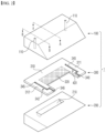
- FIG. 2 is a view illustrating a structure of a die coater 10 including a die coater shim 300 according to an embodiment of the present invention.
- the overall configuration of the die coater 10 and the die coater shim 300 will be described in detail below with reference to FIG. 2 .
- the die coater 10 includes an upper block 100 and a lower block 200, and the die coater shim 300 is interposed between the upper block 100 and the lower block 200.
- the upper block 100 and the lower block 200 are parts constituting a body of the die coater 10, an insulating coating liquid inlet 110 is provided in the upper block 100, and a manifold 210 configured to accommodate an electrode slurry supplied from an outside is provided in the lower block 200.
- the die coater shim 300 is interposed between the upper block 100 and the lower block 200 to form a slit having a height suitable for discharging the electrode slurry. Also, the die coater shim 300 serves to limit a flowing direction of the electrode slurry so that the electrode slurry is discharged toward the slit without flowing backward and serves to perform sealing so that the electrode slurry does not leak to portions other than the slit.
- the die coater shim 300 has guides 311 and 312 protruding from both ends thereof in a width direction, and a distance between the guides 311 and 312 determines a width at which the electrode slurry is applied on a current collector.
- the die coater shim 300 of the present embodiment is the same as the related art in that a slit for discharging an electrode slurry is formed therein but is different from the related art in that the die coater shim 300 of the present embodiment is configured to simultaneously discharge an insulating coating liquid and an electrode slurry.
- the die coater shim 300 of the present embodiment has an electrode slurry discharge path formed on the bottom surface of the base and an insulating coating liquid discharge path formed on the top surface of the base, and the electrode slurry discharge path and the insulating coating liquid discharge path are physically separated from each other on the die coater shim 300. Since the electrode slurry discharge path and the insulating coating liquid discharge path are physically separated in this way, even when any one liquid (the electrode slurry and/or the insulating coating liquid) leaks inside the die coater 10, the one liquid is effectively prevented from being mixed with the other liquid.
- FIG. 3 shows cross-sectional views taken along lines "A-A" and "B-B" of FIG. 2 in a state in which the die coater 10 of FIG. 2 is assembled
- FIG. 4 is a front view of the die coater 10 of FIG. 2 in the state in which the die coater 10 is assembled
- FIG. 5 is a plan view illustrating a specific structure of the die coater shim 300 illustrated in FIG. 2 .
- the die coater shim 300 includes a base 310 configured to extend in the width direction and the first and second guides 311 and 312 configured to protrude and extend from both ends of the base 310, and such a structure corresponds to the related art shown in FIG. 1 .
- the die coater shim 300 of the present embodiment includes a step portion 320 configured to extend from the base 310 in the width direction between the first and second guides 311 and 312.
- a thickness of the step portion 320 is smaller than a thickness of the base 310, and accordingly, the step portion 320 forms a stepped space relative to one surface of the base 310 (a surface thereof facing the lower block).
- the space that the step portion 320 forms communicates with the lower block 200 in which the manifold 210 is formed.
- the step portion 320 forms an electrode slurry slit 330 that forms a discharge path for the electrode slurry accommodated in the manifold 210.
- first and second guides 311 and 312 each include a groove 345 formed in a surface corresponding to the other surface of the base 310 (a surface thereof facing the upper block), and as one end of each groove 345 forms an insulating coating liquid discharge path, first and second insulating coating liquid slits 341 and 342 are provided on the first and second guides 311 and 312. Referring to the "B-B" section of FIG. 3 and the front view of FIG. 4 , the first and second insulating coating liquid slits 341 and 342 are formed toward the upper block 100, and accordingly, the electrode slurry slit 330 and the first and second insulating coating liquid slits 341 and 342 are physically separated from each other.
- upper and lower surfaces of the first and second guides 311 and 312 around the first and second insulating coating liquid slits 341 and 342 are in close contact with the upper block 100 and the lower block 200, and thus, along with the upper block 100, the first and second insulating coating liquid slits 341 and 342 form independent insulating coating liquid discharge paths isolated from surroundings thereof.
- the electrode slurry slit 330 is formed by the space that the step portion 320 between the first and second guides 311 and 312 forms, and accordingly, the electrode slurry discharge path is separated from the first and second guides 311 and 312 due to the step portion 320 and the lower block 200.
- the first and second insulating coating liquid slits 341 and 342 are disposed toward the upper block 100, and the electrode slurry discharge path is disposed toward the lower block 200 and spatially separated, even when any one solution (the electrode slurry and/or the insulating coating liquid) leaks inside the die coater 10, mixing of the two solutions hardly occurs.
- the step portion 320 may extend to a partial area in the width direction between the first and second guides 311 and 312. It is necessary for the step portion 320 to have a certain length because the step portion 320 serves to effectively separate the first and second guides 311 and 312 from the manifold 210 of the lower block 200. However, the length of the step portion 320 being too long may adversely affect a flow profile in the electrode slurry discharge path. For example, air bubbles may be present due to a vortex when the electrode slurry is discharged. Thus, there is a need to appropriately design the length of the step portion 320.
- a boundary between the base 310 and the step portion 320 may coincide with a rear end (a left side end in the "A-A" section of FIG. 3 ) of the manifold 210 provided in the lower block 200 to ensure tight sealing of the manifold 210, and an extending end portion of the step portion 320 may at least coincide with a front end of the manifold 210 or protrude from the front end of the manifold 210.
- the extending end portion of the step portion 320 may protrude 10 mm or less from the front end of the manifold 210.
- the one end of the groove 345 that forms an outlet of the first and second insulating coating liquid slits 341 and 342 may extend to protruding end portions of the first and second guides 311 and 312. Such a configuration is shown in the "B-B" section of FIG. 3 . Accordingly, the outlet of the first and second insulating coating liquid slits 341 and 342 is positioned at a sharp end portion of the die coater 10.
- the one end of the groove 345 may be spaced apart from inner corners of the first and second guides 311 and 312 that face each other.
- a distance at which the one end of the groove 345 that forms the outlet of the first and second insulating coating liquid slits 341 and 342 is spaced apart from the inner corners of the first and second guides 311 and 312 corresponds to a distance at which the one end is spaced apart from both ends of an electrode slurry discharge width defined by the inner corners of the first and second guides 311 and 312. This is to, when an electrode slurry and an insulating coating liquid are simultaneously discharged, prevent the insulating coating liquid, which has slight fluidity, from being immediately mixed with a corner of the discharged electrode slurry.
- a second embodiment of the present invention is an embodiment suitable for a case in which an electrode slurry and an insulating coating liquid are applied in two or more rows on a current collector supplied in the form of a coil and then slitting is performed.
- the second embodiment corresponds to an embodiment suitable for simultaneously applying an active material coating, which is formed of an "insulating coating liquid-electrode slurry-insulating coating liquid" structure, in two or more rows on a current collector.
- the die coater shim 300 there is no significant change in the configuration of the upper block 100 and the lower block 200 constituting the die coater 10, and a main difference is in the die coater shim 300.
- additional insulating coating liquid slits 343 and 344 are present in the die coater shim 300 of the second embodiment, an additional insulating coating liquid inlet 110 corresponding thereto may be required in the upper block 100.
- the configuration of the die coater shim 300 according to the second embodiment is shown in FIG. 7 , and the second embodiment will be described focusing on the differences from the first embodiment described above.
- the die coater shim 300 of the second embodiment further includes a third guide 313 positioned between the first and second guides 311 and 312 and configured to protrude and extend from an intermediate portion of the base 310.
- the step portion 320 is separated into a first step portion 321 disposed between the first guide and the third guide 313 and a second step portion 322 disposed between the third and second guides.
- the electrode slurry slit 330 is divided into a first electrode slurry slit 331 configured to form one electrode slurry discharge path using the first step portion 321 and a second electrode slurry slit 332 configured to form another electrode slurry discharge path using the second step portion 322.
- a pair of grooves 345 are formed on a surface of the third guide 313 that corresponds to the other surface of the base 310 (the surface thereof facing the upper block), and one ends of the pair of grooves 345 constitute third and fourth insulating coating liquid slits 343 and 344 that form additional insulating coating liquid discharge paths.
- a structure that the first and third guides 311 and 313 constitute and a structure that the third and second guides 313 and 312 constitute are symmetrical to each other. That is, the die coater shim 300 of the second embodiment may be described as a structure in which two die coater shims 300 of the first embodiment are coupled in parallel in a transfer direction of the current collector A (see FIG. 6 ).
- an active material may be simultaneously applied in two rows on a current collector in order to be suitable for slitting.
- widths of the first and second step portions 321 and 322 may be made equal to each other.
- the width of the insulating coating liquid is almost constant regardless of the width of the electrode slurry, there is no need to significantly change the configuration of the third and fourth insulating coating liquid slits 343 and 344.
- the present invention is suitable for application to a die coater for simultaneously coating an electrode slurry and an insulating coating liquid on a current collector for a secondary battery.
Landscapes
- Engineering & Computer Science (AREA)
- Manufacturing & Machinery (AREA)
- Chemical & Material Sciences (AREA)
- Chemical Kinetics & Catalysis (AREA)
- Electrochemistry (AREA)
- General Chemical & Material Sciences (AREA)
- Coating Apparatus (AREA)
- Battery Electrode And Active Subsutance (AREA)
Abstract
Description
- The present application claims the benefit of priority based on
Korean Patent Application No. 10-2021-0167134, filed on November 29, 2021 - The present invention relates to a die coater shim and die coater for effectively and simultaneously coating an electrode slurry and an insulating coating liquid on a current collector for a secondary battery.
- With the development of technology and an increase in demand for mobile devices, the demand for secondary batteries is also rapidly increasing. Among secondary batteries, lithium secondary batteries are widely used as an energy source of various electronic products as well as various mobile devices due to having high energy density and high operating voltage and being excellent in terms of preservation and lifespan.
- An electrode in which an active material layer and an insulating layer are formed on a surface of a current collector is used in a lithium secondary battery or the like. Such an electrode is manufactured by applying both an electrode slurry including an active material or the like and an insulating coating liquid including an insulating material or the like on a surface of a current collector using a coating apparatus such as a die coater so that the electrode slurry and the insulating coating liquid overlap with a portion of a corner of an electrode mixture layer and drying the electrode slurry and the insulating coating liquid.
-
FIG. 1 illustrates a conventional diecoater 1 for applying an electrode slurry. Thedie coater 1 includes anupper block 2 and a lower block 3, a die coater shim 4 is interposed between theupper block 2 and the lower block 3, and theupper block 2, the lower block 3, and the die coater shim 4 are fastened using a plurality of bolt members and coupled to each other. A manifold 5 configured to accommodate a certain volume of electrode slurry is provided in the lower block 3, and the manifold 5 communicates with an external electrode slurry supply (not illustrated). - Here, the die coater shim simultaneously serves to form a slit of a suitable height between the upper block and the lower block, limit a flowing direction of an electrode slurry so that the electrode slurry is discharged toward the slit, and perform sealing so that the electrode slurry does not leak to portions other than the slit. The die coater shim has guides protruding from both ends thereof in a width direction, and a distance between the guides determines a width at which the electrode slurry is applied on a current collector.
- An insulating coating liquid is applied on both corners in the width direction of the electrode slurry applied on the current collector. Generally, applying the insulating coating liquid is performed as an additional process using a separate apparatus after applying the electrode slurry on the current collector. Applying the electrode slurry and the insulating coating liquid on the current collector through separate processes in this way is undesirable in terms of production efficiency.
- In order to address such a problem, a technology that forms independent slits, each discharging an electrode slurry and an insulating coating liquid, in a single die coater shim has been introduced, but there is a problem that, in a case in which any one solution leaks in the die coater, the two solutions (the electrode slurry and the insulating coating liquid) are mixed, or the two solutions are mixed and discharged from an outlet of the slit, which may cause poor quality of a current collector.
- An object of the present invention is to provide a die coater shim and die coater for simultaneously and effectively coating an electrode slurry and an insulating coating liquid on a current collector for a secondary battery.
- A die coater shim and die coater for simultaneously and effectively coating an electrode slurry and an insulating coating liquid are provided. In one embodiment, a die coater shim according to the present invention includes: a base configured to extend in a width direction; first and second guides configured to protrude and extend from both ends of the base; an electrode slurry slit including a step portion configured to extend from the base in the width direction between the first and second guides, wherein a thickness of the step portion is smaller than a thickness of the base, and a stepped space that the step portion forms relative to one surface of the base forms an electrode slurry discharge path; and first and second insulating coating liquid slits including a groove formed on a surface of each of the first and second guides that corresponds to the other surface of the base, wherein one end of the groove forms an insulating coating liquid discharge path.
- In a specific embodiment, the step portion may extend to a partial area in the width direction between the first and second guides.
- Also, the one end of the groove that forms an outlet of the first and second insulating coating liquid slits may extend to protruding end portions of the first and second guides.
- In a specific embodiment, the one end of the groove may be spaced apart from inner corners of the first and second guides that face each other.
- In another embodiment, the die coater shim may further include a third guide positioned between the first and second guides and configured to protrude and extend from the base, the step portion may be formed of a first step portion disposed between the first and third guides and a second step portion disposed between the third and second guides, the electrode slurry slit may be formed of a first electrode slurry slit configured to form a first electrode slurry discharge path using the first step portion and a second electrode slurry slit configured to form a second electrode slurry discharge path using the second step portion, and the die coater shim may further include third and fourth insulating coating liquid slits including a pair of grooves formed on a surface of the third guide that corresponds to the other surface of the base, wherein one end of each of the pair of grooves forms an insulating coating liquid discharge path.
- In a specific embodiment, outlets of the third and fourth insulating coating liquid slits may face the first and second guides.
- Further, widths of the first and second step portions may be equal to each other.
- Meanwhile, an aspect of the present invention provides a die coater including: an upper block in which an insulating coating liquid inlet is provided; a lower block coupled to the upper block and in which a manifold configured to accommodate an electrode slurry is provided; and a die coater shim interposed between the upper block and the lower block to form a slit and configured to simultaneously discharge an insulating coating liquid and the electrode slurry through the slit, wherein the die coater shim has an electrode slurry discharge path formed on one surface and an insulating coating liquid discharge path formed on the other surface opposite to the one surface, and the electrode slurry discharge path and the insulating coating liquid discharge path are physically separated from each other on the die coater shim.
- In one embodiment, the die coater shim may include: a base configured to extend in a width direction; first and second guides configured to protrude and extend from both ends of the base; an electrode slurry slit including a step portion configured to extend from the base in the width direction between the first and second guides, wherein a thickness of the step portion is smaller than a thickness of the base, and a stepped space that the step portion forms relative to one surface of the base forms an electrode slurry discharge path; and first and second insulating coating liquid slits including a groove formed on a surface of each of the first and second guides that corresponds to the other surface of the base, wherein one end of the groove forms an insulating coating liquid discharge path.
- Further, the step portion may extend to a partial area in the width direction between the first and second guides.
- In a specific embodiment, a boundary between the base and the step portion may coincide with a rear end of the manifold provided in the lower block, and an end portion of the step portion may coincide with a front end of the manifold or protrude from the front end of the manifold.
- For example, the end portion of the step portion may protrude 10 mm or less from the front end of the manifold.
- In another embodiment, the one end of the groove that forms an outlet of the first and second insulating coating liquid slits may extend to protruding end portions of the first and second guides.
- In a specific embodiment, the one end of the groove may be spaced apart from inner corners of the first and second guides that face each other.
- A die coater shim of the present invention is configured to simultaneously discharge an insulating coating liquid and an electrode slurry, and in particular, an electrode slurry discharge path and an insulating coating liquid discharge path are physically separated from each other on the die coater shim.
- Accordingly, the die coater shim of the present invention effectively prevents the electrode slurry and the insulating coating liquid from being mixed with each other even when the electrode slurry and/or the insulating coating liquid leak inside a die coater.
- Therefore, the present invention allows an electrode slurry and an insulating coating liquid to be simultaneously and effectively coated on a current collector for a secondary battery.
- Advantageous effects of the present invention are not limited to those mentioned above, and other unmentioned advantageous effects should be clearly understood by those of ordinary skill in the art from the detailed description below.
-
-
FIG. 1 is a view illustrating a configuration of a die coater according to the related art. -
FIG. 2 is a view illustrating a structure of a die coater including a die coater shim according to an embodiment of the present invention. -
FIG. 3 shows cross-sectional views taken along lines "A-A" and "B-B" ofFIG. 2 in a state in which the die coater ofFIG. 2 is assembled. -
FIG. 4 is a front view of the die coater ofFIG. 2 in the state in which the die coater is assembled. -
FIG. 5 is a view illustrating a specific structure of the die coater shim illustrated inFIG. 2 . -
FIG. 6 is a view schematically illustrating a state in which an electrode slurry and an insulating coating liquid are simultaneously applied using the die coater ofFIG. 2 . -
FIG. 7 is a view illustrating a die coater shim according to another embodiment of the present invention. - Since various modifications may be made to the present invention and the present invention may have various embodiments, specific embodiments will be described in detail below.
- However, this does not limit the present invention to the specific embodiments, and all modifications, equivalents, or substitutes included in the spirit and technical scope of the present invention should be understood as belonging to the present invention.
- In the present disclosure, terms such as "include" or "have" should be understood as specifying that features, numbers, steps, operations, elements, components, or combinations thereof are present and not as precluding the possibility of the presence or addition of one or more other features, numbers, steps, operations, elements, components, or combinations thereof in advance.
- Also, in the present disclosure, when a part such as a layer, a film, an area, or a plate is described as being "on" another part, this includes not only a case where the part is "directly on" the other part, but also a case where still another part is present therebetween. On the contrary, when a part such as a layer, a film, an area, or a plate is described as being "under" another part, this includes not only a case where the part is "directly under" the other part, but also a case where still another part is present therebetween. Also, in the present application, being disposed "on" may include not only being disposed on an upper portion, but also being disposed on a lower portion.
- The present Invention provides a die coater shim and die coater for simultaneously and effectively coating an electrode slurry and an insulating coating liquid.
- In one embodiment, a die coater shim according to the present invention includes: a base configured to extend in a width direction; first and second guides configured to protrude and extend from both ends of the base; an electrode slurry slit including a step portion configured to extend from the base in the width direction between the first and second guides, wherein a thickness of the step portion is smaller than a thickness of the base, and a stepped space that the step portion forms relative to one surface of the base forms an electrode slurry discharge path; and first and second insulating coating liquid slits including a groove formed on a surface of each of the first and second guides that corresponds to the other surface of the base, wherein one end of the groove forms an insulating coating liquid discharge path.
- In particular, since the die coater shim according to the present invention has the electrode slurry discharge path formed on one surface and the insulating coating liquid discharge path formed on the other surface opposite to the one surface, the die coater shim can simultaneously apply an electrode slurry and an insulating coating liquid on a current collector. Further, since the electrode slurry discharge path and the insulating coating liquid discharge path are physically separated from each other on the die coater shim, even when any one solution leaks in a die coater, the two solutions are prevented from being mixed with each other.
- Hereinafter, a die coater shim and die coater for simultaneously and effectively coating an electrode slurry and an insulating coating liquid on a current collector for a secondary battery according to embodiments of the present invention will be described in detail with reference to the accompanying drawings.
-
FIG. 2 is a view illustrating a structure of adie coater 10 including adie coater shim 300 according to an embodiment of the present invention. The overall configuration of thedie coater 10 and thedie coater shim 300 will be described in detail below with reference toFIG. 2 . - The
die coater 10 includes anupper block 100 and alower block 200, and thedie coater shim 300 is interposed between theupper block 100 and thelower block 200. - The
upper block 100 and thelower block 200 are parts constituting a body of thedie coater 10, an insulatingcoating liquid inlet 110 is provided in theupper block 100, and a manifold 210 configured to accommodate an electrode slurry supplied from an outside is provided in thelower block 200. - The
die coater shim 300 is interposed between theupper block 100 and thelower block 200 to form a slit having a height suitable for discharging the electrode slurry. Also, thedie coater shim 300 serves to limit a flowing direction of the electrode slurry so that the electrode slurry is discharged toward the slit without flowing backward and serves to perform sealing so that the electrode slurry does not leak to portions other than the slit. - As illustrated in
FIG. 2 , thedie coater shim 300 hasguides guides - The
die coater shim 300 of the present embodiment is the same as the related art in that a slit for discharging an electrode slurry is formed therein but is different from the related art in that thedie coater shim 300 of the present embodiment is configured to simultaneously discharge an insulating coating liquid and an electrode slurry. - In particular, the
die coater shim 300 of the present embodiment has an electrode slurry discharge path formed on the bottom surface of the base and an insulating coating liquid discharge path formed on the top surface of the base, and the electrode slurry discharge path and the insulating coating liquid discharge path are physically separated from each other on thedie coater shim 300. Since the electrode slurry discharge path and the insulating coating liquid discharge path are physically separated in this way, even when any one liquid (the electrode slurry and/or the insulating coating liquid) leaks inside thedie coater 10, the one liquid is effectively prevented from being mixed with the other liquid. - A specific configuration of the
die coater shim 300 of the present embodiment will be described in detail with reference toFIGS. 3 to 5 .FIG. 3 shows cross-sectional views taken along lines "A-A" and "B-B" ofFIG. 2 in a state in which thedie coater 10 ofFIG. 2 is assembled,FIG. 4 is a front view of thedie coater 10 ofFIG. 2 in the state in which thedie coater 10 is assembled, andFIG. 5 is a plan view illustrating a specific structure of thedie coater shim 300 illustrated inFIG. 2 . - First, referring to
FIG. 5 , thedie coater shim 300 includes a base 310 configured to extend in the width direction and the first andsecond guides base 310, and such a structure corresponds to the related art shown inFIG. 1 . - Here, the
die coater shim 300 of the present embodiment includes astep portion 320 configured to extend from the base 310 in the width direction between the first andsecond guides step portion 320 is smaller than a thickness of thebase 310, and accordingly, thestep portion 320 forms a stepped space relative to one surface of the base 310 (a surface thereof facing the lower block). As shown in the "A-A" section ofFIG. 3 and the front view ofFIG. 4 , the space that thestep portion 320 forms communicates with thelower block 200 in which themanifold 210 is formed. Thus, thestep portion 320 forms an electrode slurry slit 330 that forms a discharge path for the electrode slurry accommodated in themanifold 210. - Also, the first and
second guides groove 345 formed in a surface corresponding to the other surface of the base 310 (a surface thereof facing the upper block), and as one end of eachgroove 345 forms an insulating coating liquid discharge path, first and second insulating coatingliquid slits second guides FIG. 3 and the front view ofFIG. 4 , the first and second insulating coatingliquid slits upper block 100, and accordingly, the electrode slurry slit 330 and the first and second insulating coatingliquid slits - That is, upper and lower surfaces of the first and
second guides liquid slits upper block 100 and thelower block 200, and thus, along with theupper block 100, the first and second insulating coatingliquid slits - Also, the electrode slurry slit 330 is formed by the space that the
step portion 320 between the first andsecond guides second guides step portion 320 and thelower block 200. - Therefore, since, inside the
die coater 10, the first and second insulating coatingliquid slits upper block 100, and the electrode slurry discharge path is disposed toward thelower block 200 and spatially separated, even when any one solution (the electrode slurry and/or the insulating coating liquid) leaks inside thedie coater 10, mixing of the two solutions hardly occurs. - In an embodiment of the present invention, the
step portion 320 may extend to a partial area in the width direction between the first andsecond guides step portion 320 to have a certain length because thestep portion 320 serves to effectively separate the first andsecond guides manifold 210 of thelower block 200. However, the length of thestep portion 320 being too long may adversely affect a flow profile in the electrode slurry discharge path. For example, air bubbles may be present due to a vortex when the electrode slurry is discharged. Thus, there is a need to appropriately design the length of thestep portion 320. - In a specific embodiment, a boundary between the base 310 and the
step portion 320 may coincide with a rear end (a left side end in the "A-A" section ofFIG. 3 ) of the manifold 210 provided in thelower block 200 to ensure tight sealing of the manifold 210, and an extending end portion of thestep portion 320 may at least coincide with a front end of the manifold 210 or protrude from the front end of themanifold 210. For example, the extending end portion of thestep portion 320 may protrude 10 mm or less from the front end of themanifold 210. - Also, the one end of the
groove 345 that forms an outlet of the first and second insulating coatingliquid slits second guides FIG. 3 . Accordingly, the outlet of the first and second insulating coatingliquid slits die coater 10. - Also, in a specific embodiment, the one end of the
groove 345 may be spaced apart from inner corners of the first andsecond guides groove 345 that forms the outlet of the first and second insulating coatingliquid slits second guides second guides die coater 10 of the present invention is shown inFIG. 6 . - A second embodiment of the present invention is an embodiment suitable for a case in which an electrode slurry and an insulating coating liquid are applied in two or more rows on a current collector supplied in the form of a coil and then slitting is performed.
- That is, the second embodiment corresponds to an embodiment suitable for simultaneously applying an active material coating, which is formed of an "insulating coating liquid-electrode slurry-insulating coating liquid" structure, in two or more rows on a current collector.
- In the second embodiment, there is no significant change in the configuration of the
upper block 100 and thelower block 200 constituting thedie coater 10, and a main difference is in thedie coater shim 300. However, since additional insulating coating liquid slits 343 and 344 are present in thedie coater shim 300 of the second embodiment, an additional insulating coatingliquid inlet 110 corresponding thereto may be required in theupper block 100. - The configuration of the
die coater shim 300 according to the second embodiment is shown inFIG. 7 , and the second embodiment will be described focusing on the differences from the first embodiment described above. - Referring to
FIG. 7 , thedie coater shim 300 of the second embodiment further includes athird guide 313 positioned between the first andsecond guides base 310. - Also, as the
third guide 313 is provided on the intermediate portion of thebase 310, thestep portion 320 is separated into afirst step portion 321 disposed between the first guide and thethird guide 313 and asecond step portion 322 disposed between the third and second guides. Also, corresponding thereto, the electrode slurry slit 330 is divided into a first electrode slurry slit 331 configured to form one electrode slurry discharge path using thefirst step portion 321 and a second electrode slurry slit 332 configured to form another electrode slurry discharge path using thesecond step portion 322. - Also, a pair of
grooves 345 are formed on a surface of thethird guide 313 that corresponds to the other surface of the base 310 (the surface thereof facing the upper block), and one ends of the pair ofgrooves 345 constitute third and fourth insulating coatingliquid slits - Referring to
FIG. 7 with reference to the first embodiment, a structure that the first andthird guides second guides die coater shim 300 of the second embodiment may be described as a structure in which two diecoater shims 300 of the first embodiment are coupled in parallel in a transfer direction of the current collector A (seeFIG. 6 ). - Therefore, using the
die coater shim 300 ofFIG. 7 , an active material may be simultaneously applied in two rows on a current collector in order to be suitable for slitting. In a case in which widths of two rows of electrode slurries are equal to each other, widths of the first andsecond step portions liquid slits - The present invention has been described in detail above using the drawings, embodiments, or the like. However, configurations illustrated or described in the drawings or embodiments herein are only some embodiments of the present invention and do not represent the entire technical spirit of the present invention. Therefore, it should be understood that various equivalents and modifications that may replace the corresponding configurations may be present at the time of filing this application.
-
- 10: die coater
- 100: upper block
- 110: insulating coating liquid inlet
- 200: lower block
- 210: manifold
- 300: die coater shim
- 310: base
- 311; first guide
- 312: second guide
- 313: third guide
- 320: step portion
- 321: first step portion
- 322: second step portion
- 330: electrode slurry slit
- 331: first electrode slurry slit
- 332: second electrode slurry slit
- 341: first insulating coating liquid slit
- 342: second insulating coating liquid slit
- 343: third insulating coating liquid slit
- 344: fourth insulating coating liquid slit
- 345: groove
- The present invention is suitable for application to a die coater for simultaneously coating an electrode slurry and an insulating coating liquid on a current collector for a secondary battery.
Claims (14)
- A die coater shim for simultaneously applying an electrode slurry and an insulating coating liquid on a current collector, the die coater shim comprising:a base configured to extend in a width direction;first and second guides disposed on each end of the base in the width direction, wherein the first and second guides protrude and extend from the base in a direction orthogonal to the width direction;a first electrode slurry slit including a first step portion disposed between the first and second guides in the width direction, wherein a thickness of the first step portion is smaller than a thickness of the base, wherein the thickness of the first step portion forms a first stepped space relative to a first surface of the base, wherein the first stepped space forms an electrode slurry discharge path; andfirst and second insulating coating liquid slits including a groove formed on a surface of each of the first and second guides disposed on a second surface of the base, wherein one end of each of the grooves forms an insulating coating liquid discharge path.
- The die coater shim of claim 1, wherein the step portion extends to a partial area in the width direction between the first and second guides, wherein the first and second guides protrude and extend from the partial area in the direction orthogonal to the width direction.
- The die coater shim of claim 1, wherein the one end of each of the grooves forms an outlet of the first and second insulating coating liquid slits, wherein the one end of each of the grooves extends to a protruding end portion of each of the first and second guides.
- The die coater shim of claim 3, wherein the one end of each of the grooves is spaced further apart in the width direction from inner corners of the first and second guides.
- The die coater shim of claim 1, further comprising:a third guide positioned between the first and second guides, wherein the third guide protrudes and extends from the base in the direction orthogonal to the width direction; andthird and fourth insulating coating liquid slits including a pair of grooves formed on a surface of the third guide, wherein one end of each of the pair of grooves forms an insulating coating liquid discharge path,wherein the step portion includes a first step portion and a second step portion, wherein the first step portion is disposed between the first and third guides and the second step portion is disposed between the third and second guides,wherein the electrode slurry slit includes the first electrode slurry slit and a second electrode slurry slit, wherein the second electrode slurry slit includes a second step portion, wherein a second thickness of the second step portion is smaller than the thickness of the base, wherein the thickness the second step portion forms a second stepped space relative to the first surface of the base, wherein the second stepped space forms a second electrode slurry discharge path.
- The die coater shim of claim 5, wherein an outlet of the third insulating coating liquid slit faces the first guide and an outlet of the fourth insulating coating liquid faces the second guide.
- The die coater shim of claim 5, wherein a width of each of the first and second step portions are equal.
- A die coater comprising:an upper block having an insulating coating liquid inlet;a lower block coupled to the upper block, wherein the lower block includes a manifold configured to accommodate an electrode slurry; anda die coater shim interposed between the upper block and the lower block so as to form a slit, wherein the die coater is configured to simultaneously discharge an insulating coating liquid and the electrode slurry through the slit,wherein the die coater shim has an electrode slurry discharge path formed on a first surface of the base and an insulating coating liquid discharge path formed on a second surface of the base,wherein the electrode slurry discharge path and the insulating coating liquid discharge path are physically separated from each other on the die coater shim.
- The die coater of claim 8, wherein the die coater shim includes:a base configured to extend in a width direction;first and second guides disposed on each end of the base in the width direction, wherein the first and second guides protrude and extend from the base in a direction orthogonal to the width direction;an electrode slurry slit including a step portion disposed between the first and second guides in the width direction, wherein a thickness of the step portion is smaller than a thickness of the base, wherein the thickness of the step portions forms a stepped space relative to a first surface of the base, wherein the stepped space forms the electrode slurry discharge path; andfirst and second insulating coating liquid slits including a groove formed on a surface of each of the first and second guides disposed on a second surface of the base, wherein one end of each of the grooves form the insulating coating liquid discharge path.
- The die coater of claim 9, wherein the step portion extends to a partial area in the width direction between the first and second guides, wherein the first and second guides protrude and extend from the partial area in the direction orthogonal to the width direction.
- The die coater of claim 10, wherein:a boundary between the base and the step portion coincides with a rear end of the manifold provided in the lower block, wherein the rear end of the manifold is disposed adjacent to the base of the die coater; andan end portion of the step portion coincides with a front end of the manifold or protrudes from the front end of the manifold, wherein the front end of the manifold is disposed further away from the base of the die coater than the rear end of the manifold.
- The die coater of claim 11, wherein the end portion of the step portion protrudes 10 mm or less from the front end of the manifold.
- The die coater of claim 9, wherein the one end of each of the grooves forms an outlet of the first and second insulating coating liquid slits, wherein the one end of each of the grooves extends to a protruding end portion of each of the first and second guides.
- The die coater of claim 13, wherein the one end of each of the grooves is spaced further apart in the width direction from inner corners of the first and second guides.
Applications Claiming Priority (2)
| Application Number | Priority Date | Filing Date | Title |
|---|---|---|---|
| KR1020210167134A KR102872643B1 (en) | 2021-11-29 | 2021-11-29 | Die coater shim and die coater for coating of electrode slurry on secondary cell electrode |
| PCT/KR2022/016788 WO2023096191A1 (en) | 2021-11-29 | 2022-10-31 | Shim for die coater and die coater for coating active material on current collector for secondary battery |
Publications (3)
| Publication Number | Publication Date |
|---|---|
| EP4243109A1 true EP4243109A1 (en) | 2023-09-13 |
| EP4243109A4 EP4243109A4 (en) | 2024-07-17 |
| EP4243109B1 EP4243109B1 (en) | 2025-06-11 |
Family
ID=86539826
Family Applications (1)
| Application Number | Title | Priority Date | Filing Date |
|---|---|---|---|
| EP22898873.9A Active EP4243109B1 (en) | 2021-11-29 | 2022-10-31 | Die coater shim and die coater for coating active material on current collector for secondary battery |
Country Status (9)
| Country | Link |
|---|---|
| US (1) | US20240024911A1 (en) |
| EP (1) | EP4243109B1 (en) |
| JP (1) | JP7596017B2 (en) |
| KR (1) | KR102872643B1 (en) |
| CN (1) | CN116569382A (en) |
| ES (1) | ES3034927T3 (en) |
| HU (1) | HUE072054T2 (en) |
| PL (1) | PL4243109T3 (en) |
| WO (1) | WO2023096191A1 (en) |
Families Citing this family (7)
| Publication number | Priority date | Publication date | Assignee | Title |
|---|---|---|---|---|
| KR20220059744A (en) * | 2020-11-03 | 2022-05-10 | 주식회사 엘지에너지솔루션 | Shim for die coater, die coater including the same, and lithium secondary battery including a positive electrode manufactured using the same |
| KR20250140896A (en) * | 2024-03-19 | 2025-09-26 | 주식회사 엘지에너지솔루션 | Coating apparatus |
| KR20250175511A (en) | 2024-06-10 | 2025-12-17 | 주식회사 엘지에너지솔루션 | Coating apparatus |
| KR20260000681A (en) * | 2024-06-26 | 2026-01-05 | 주식회사 엘지에너지솔루션 | Die coater |
| KR20260001377A (en) * | 2024-06-27 | 2026-01-05 | 삼성에스디아이 주식회사 | Slot Die Coater |
| KR20260038097A (en) * | 2024-09-11 | 2026-03-18 | 삼성에스디아이 주식회사 | Apparatus and method for coating of electrode plate and slot die used for them |
| JP2026064272A (en) * | 2024-10-02 | 2026-04-14 | 東レエンジニアリング株式会社 | coating device |
Family Cites Families (19)
| Publication number | Priority date | Publication date | Assignee | Title |
|---|---|---|---|---|
| US9233500B2 (en) * | 2010-02-08 | 2016-01-12 | 3M Innovative Properties Company | Method of co-extruding, co-extrusion die, and extruded articles made therefrom |
| JP5542523B2 (en) * | 2010-05-18 | 2014-07-09 | 株式会社ヒラノテクシード | Slit die |
| KR101308251B1 (en) * | 2011-03-18 | 2013-09-13 | 삼성에스디아이 주식회사 | Slot Die |
| KR102056479B1 (en) * | 2012-12-12 | 2019-12-16 | 광주과학기술원 | Slot-die performing multi-coating |
| JP6096077B2 (en) * | 2013-07-25 | 2017-03-15 | オートモーティブエナジーサプライ株式会社 | Coating head and coating apparatus using the same |
| KR101762813B1 (en) * | 2015-01-14 | 2017-07-28 | 주식회사 엘지화학 | Slot Die Having Two Shims and Coating Device Comprising the Same |
| KR101737683B1 (en) * | 2015-01-16 | 2017-05-29 | 주식회사 엘지화학 | Flow control member for die coater and Coating apparatus comprising the same |
| KR102134587B1 (en) * | 2016-02-12 | 2020-07-16 | 주식회사 엘지화학 | Electrode Coating Apparatus Capable of Simultaneously Coating Different Substances Constituting Electrode for Secondary Battery |
| CN110198792B (en) | 2017-02-03 | 2021-10-26 | 日本汽车能源株式会社 | Coating die, coating device, coating method, and method for manufacturing secondary battery |
| CN208173722U (en) * | 2017-08-24 | 2018-11-30 | 日立汽车系统株式会社 | Secondary cell |
| JP7155881B2 (en) * | 2018-10-31 | 2022-10-19 | トヨタ自動車株式会社 | Electrode plate, battery using same, method for manufacturing electrode plate, method for manufacturing battery using same, die head |
| TWM577762U (en) * | 2018-12-07 | 2019-05-11 | 財團法人工業技術研究院 | Clamp plate and slot die coating device using same |
| JP7124695B2 (en) | 2018-12-27 | 2022-08-24 | トヨタ自動車株式会社 | Positive electrode manufacturing equipment |
| CN209646879U (en) * | 2019-01-23 | 2019-11-19 | 欣旺达电子股份有限公司 | It is coated with gasket |
| KR102035826B1 (en) * | 2019-05-31 | 2019-10-24 | 씨아이에스(주) | Multi-row simultaneous coating slot die |
| JP7368125B2 (en) * | 2019-07-05 | 2023-10-24 | 株式会社Aescジャパン | Coating device and method for manufacturing electrodes for batteries |
| KR20210083512A (en) | 2019-12-27 | 2021-07-07 | 주식회사 엘지에너지솔루션 | Electrode slurry coating shim with excellent coating uniformity and coating die comprising the same |
| JP2021120148A (en) | 2020-01-30 | 2021-08-19 | トヨタ自動車株式会社 | Die coating device |
| CN113510044B (en) * | 2021-04-30 | 2022-10-04 | 西安瑟福能源科技有限公司 | A small area density slit coating gasket |
-
2021
- 2021-11-29 KR KR1020210167134A patent/KR102872643B1/en active Active
-
2022
- 2022-10-31 JP JP2023535042A patent/JP7596017B2/en active Active
- 2022-10-31 CN CN202280007894.XA patent/CN116569382A/en active Pending
- 2022-10-31 HU HUE22898873A patent/HUE072054T2/en unknown
- 2022-10-31 PL PL22898873.9T patent/PL4243109T3/en unknown
- 2022-10-31 US US18/266,330 patent/US20240024911A1/en active Pending
- 2022-10-31 ES ES22898873T patent/ES3034927T3/en active Active
- 2022-10-31 WO PCT/KR2022/016788 patent/WO2023096191A1/en not_active Ceased
- 2022-10-31 EP EP22898873.9A patent/EP4243109B1/en active Active
Also Published As
| Publication number | Publication date |
|---|---|
| CN116569382A (en) | 2023-08-08 |
| HUE072054T2 (en) | 2025-10-28 |
| EP4243109A4 (en) | 2024-07-17 |
| KR20230079911A (en) | 2023-06-07 |
| JP2024501439A (en) | 2024-01-12 |
| WO2023096191A1 (en) | 2023-06-01 |
| JP7596017B2 (en) | 2024-12-09 |
| US20240024911A1 (en) | 2024-01-25 |
| ES3034927T3 (en) | 2025-08-26 |
| KR102872643B1 (en) | 2025-10-16 |
| EP4243109B1 (en) | 2025-06-11 |
| PL4243109T3 (en) | 2025-08-18 |
Similar Documents
| Publication | Publication Date | Title |
|---|---|---|
| EP4243109A1 (en) | Shim for die coater and die coater for coating active material on current collector for secondary battery | |
| EP4289518A1 (en) | Die coater for coating secondary battery current collector with active material | |
| EP4321264B1 (en) | Die coater capable of multi-layer coating of active materials | |
| EP3578272A1 (en) | Coating die, coating device, coating method, and method for manufacturing secondary cell | |
| US20250050372A1 (en) | Die Coater for Coating Active Material of Secondary Battery Current Collector | |
| KR20220148284A (en) | End Cover Assemblies, Battery Cells, Battery Packs and Devices | |
| EP4410439A1 (en) | Coating die head, and coating device for battery electrode plate | |
| EP4353365A1 (en) | Die coater for coating active material of secondary battery current collector | |
| US20240238827A1 (en) | Coating die and battery electrode plate coating apparatus | |
| KR102874374B1 (en) | Slot die coater | |
| US20250091085A1 (en) | Coating die head and coating apparatus | |
| EP4534210B1 (en) | Die coater for coating electrode slurry and insulating liquid | |
| US20260088313A1 (en) | Bipolar plate and electrochemical cell | |
| JP7664497B1 (en) | Slot Die Coater | |
| CN116134651A (en) | Energy storage devices, especially redox flow batteries | |
| KR20250085633A (en) | Die coater, coating equipment including the same and electrode coating method using the same | |
| JP2026508470A (en) | Slot die with split manifold | |
| CN121222623A (en) | Slit mold coating machine | |
| KR20250156306A (en) | Dual slot die coater | |
| CN119907719A (en) | Spacer and slot die coaters |
Legal Events
| Date | Code | Title | Description |
|---|---|---|---|
| STAA | Information on the status of an ep patent application or granted ep patent |
Free format text: STATUS: THE INTERNATIONAL PUBLICATION HAS BEEN MADE |
|
| PUAI | Public reference made under article 153(3) epc to a published international application that has entered the european phase |
Free format text: ORIGINAL CODE: 0009012 |
|
| STAA | Information on the status of an ep patent application or granted ep patent |
Free format text: STATUS: REQUEST FOR EXAMINATION WAS MADE |
|
| 17P | Request for examination filed |
Effective date: 20230605 |
|
| AK | Designated contracting states |
Kind code of ref document: A1 Designated state(s): AL AT BE BG CH CY CZ DE DK EE ES FI FR GB GR HR HU IE IS IT LI LT LU LV MC ME MK MT NL NO PL PT RO RS SE SI SK SM TR |
|
| A4 | Supplementary search report drawn up and despatched |
Effective date: 20240617 |
|
| RIC1 | Information provided on ipc code assigned before grant |
Ipc: B05C 9/06 20060101ALI20240611BHEP Ipc: B05C 5/02 20060101ALI20240611BHEP Ipc: H01M 10/42 20060101ALI20240611BHEP Ipc: H01M 4/04 20060101AFI20240611BHEP |
|
| GRAP | Despatch of communication of intention to grant a patent |
Free format text: ORIGINAL CODE: EPIDOSNIGR1 |
|
| STAA | Information on the status of an ep patent application or granted ep patent |
Free format text: STATUS: GRANT OF PATENT IS INTENDED |
|
| DAV | Request for validation of the european patent (deleted) | ||
| DAX | Request for extension of the european patent (deleted) | ||
| RIC1 | Information provided on ipc code assigned before grant |
Ipc: B05C 9/06 20060101ALI20250129BHEP Ipc: B05C 5/02 20060101ALI20250129BHEP Ipc: H01M 10/42 20060101ALI20250129BHEP Ipc: H01M 4/04 20060101AFI20250129BHEP |
|
| INTG | Intention to grant announced |
Effective date: 20250219 |
|
| P01 | Opt-out of the competence of the unified patent court (upc) registered |
Free format text: CASE NUMBER: APP_13987/2025 Effective date: 20250321 |
|
| GRAS | Grant fee paid |
Free format text: ORIGINAL CODE: EPIDOSNIGR3 |
|
| GRAA | (expected) grant |
Free format text: ORIGINAL CODE: 0009210 |
|
| STAA | Information on the status of an ep patent application or granted ep patent |
Free format text: STATUS: THE PATENT HAS BEEN GRANTED |
|
| AK | Designated contracting states |
Kind code of ref document: B1 Designated state(s): AL AT BE BG CH CY CZ DE DK EE ES FI FR GB GR HR HU IE IS IT LI LT LU LV MC ME MK MT NL NO PL PT RO RS SE SI SK SM TR |
|
| REG | Reference to a national code |
Ref country code: GB Ref legal event code: FG4D |
|
| REG | Reference to a national code |
Ref country code: CH Ref legal event code: EP |
|
| REG | Reference to a national code |
Ref country code: IE Ref legal event code: FG4D |
|
| REG | Reference to a national code |
Ref country code: DE Ref legal event code: R096 Ref document number: 602022015938 Country of ref document: DE |
|
| REG | Reference to a national code |
Ref country code: ES Ref legal event code: FG2A Ref document number: 3034927 Country of ref document: ES Kind code of ref document: T3 Effective date: 20250826 |
|
| PG25 | Lapsed in a contracting state [announced via postgrant information from national office to epo] |
Ref country code: FI Free format text: LAPSE BECAUSE OF FAILURE TO SUBMIT A TRANSLATION OF THE DESCRIPTION OR TO PAY THE FEE WITHIN THE PRESCRIBED TIME-LIMIT Effective date: 20250611 |
|
| REG | Reference to a national code |
Ref country code: LT Ref legal event code: MG9D |
|
| PG25 | Lapsed in a contracting state [announced via postgrant information from national office to epo] |
Ref country code: NO Free format text: LAPSE BECAUSE OF FAILURE TO SUBMIT A TRANSLATION OF THE DESCRIPTION OR TO PAY THE FEE WITHIN THE PRESCRIBED TIME-LIMIT Effective date: 20250911 Ref country code: GR Free format text: LAPSE BECAUSE OF FAILURE TO SUBMIT A TRANSLATION OF THE DESCRIPTION OR TO PAY THE FEE WITHIN THE PRESCRIBED TIME-LIMIT Effective date: 20250912 |
|
| REG | Reference to a national code |
Ref country code: NL Ref legal event code: MP Effective date: 20250611 |
|
| PG25 | Lapsed in a contracting state [announced via postgrant information from national office to epo] |
Ref country code: BG Free format text: LAPSE BECAUSE OF FAILURE TO SUBMIT A TRANSLATION OF THE DESCRIPTION OR TO PAY THE FEE WITHIN THE PRESCRIBED TIME-LIMIT Effective date: 20250611 |
|
| PGFP | Annual fee paid to national office [announced via postgrant information from national office to epo] |
Ref country code: BE Payment date: 20250922 Year of fee payment: 4 |
|
| PG25 | Lapsed in a contracting state [announced via postgrant information from national office to epo] |
Ref country code: HR Free format text: LAPSE BECAUSE OF FAILURE TO SUBMIT A TRANSLATION OF THE DESCRIPTION OR TO PAY THE FEE WITHIN THE PRESCRIBED TIME-LIMIT Effective date: 20250611 |
|
| PGFP | Annual fee paid to national office [announced via postgrant information from national office to epo] |
Ref country code: FR Payment date: 20250925 Year of fee payment: 4 |
|
| PG25 | Lapsed in a contracting state [announced via postgrant information from national office to epo] |
Ref country code: RS Free format text: LAPSE BECAUSE OF FAILURE TO SUBMIT A TRANSLATION OF THE DESCRIPTION OR TO PAY THE FEE WITHIN THE PRESCRIBED TIME-LIMIT Effective date: 20250911 |
|
| REG | Reference to a national code |
Ref country code: HU Ref legal event code: AG4A Ref document number: E072054 Country of ref document: HU |
|
| PG25 | Lapsed in a contracting state [announced via postgrant information from national office to epo] |
Ref country code: LV Free format text: LAPSE BECAUSE OF FAILURE TO SUBMIT A TRANSLATION OF THE DESCRIPTION OR TO PAY THE FEE WITHIN THE PRESCRIBED TIME-LIMIT Effective date: 20250611 |
|
| PGFP | Annual fee paid to national office [announced via postgrant information from national office to epo] |
Ref country code: HU Payment date: 20251029 Year of fee payment: 4 |
|
| PG25 | Lapsed in a contracting state [announced via postgrant information from national office to epo] |
Ref country code: NL Free format text: LAPSE BECAUSE OF FAILURE TO SUBMIT A TRANSLATION OF THE DESCRIPTION OR TO PAY THE FEE WITHIN THE PRESCRIBED TIME-LIMIT Effective date: 20250611 |
|
| PG25 | Lapsed in a contracting state [announced via postgrant information from national office to epo] |
Ref country code: PT Free format text: LAPSE BECAUSE OF FAILURE TO SUBMIT A TRANSLATION OF THE DESCRIPTION OR TO PAY THE FEE WITHIN THE PRESCRIBED TIME-LIMIT Effective date: 20251013 |
|
| REG | Reference to a national code |
Ref country code: AT Ref legal event code: MK05 Ref document number: 1802970 Country of ref document: AT Kind code of ref document: T Effective date: 20250611 |
|
| PG25 | Lapsed in a contracting state [announced via postgrant information from national office to epo] |
Ref country code: IS Free format text: LAPSE BECAUSE OF FAILURE TO SUBMIT A TRANSLATION OF THE DESCRIPTION OR TO PAY THE FEE WITHIN THE PRESCRIBED TIME-LIMIT Effective date: 20251011 |
|
| PGFP | Annual fee paid to national office [announced via postgrant information from national office to epo] |
Ref country code: DE Payment date: 20250922 Year of fee payment: 4 |
|
| PG25 | Lapsed in a contracting state [announced via postgrant information from national office to epo] |
Ref country code: AT Free format text: LAPSE BECAUSE OF FAILURE TO SUBMIT A TRANSLATION OF THE DESCRIPTION OR TO PAY THE FEE WITHIN THE PRESCRIBED TIME-LIMIT Effective date: 20250611 Ref country code: SM Free format text: LAPSE BECAUSE OF FAILURE TO SUBMIT A TRANSLATION OF THE DESCRIPTION OR TO PAY THE FEE WITHIN THE PRESCRIBED TIME-LIMIT Effective date: 20250611 |
|
| PG25 | Lapsed in a contracting state [announced via postgrant information from national office to epo] |
Ref country code: CZ Free format text: LAPSE BECAUSE OF FAILURE TO SUBMIT A TRANSLATION OF THE DESCRIPTION OR TO PAY THE FEE WITHIN THE PRESCRIBED TIME-LIMIT Effective date: 20250611 |
|
| PGFP | Annual fee paid to national office [announced via postgrant information from national office to epo] |
Ref country code: PL Payment date: 20250926 Year of fee payment: 4 |
|
| PG25 | Lapsed in a contracting state [announced via postgrant information from national office to epo] |
Ref country code: EE Free format text: LAPSE BECAUSE OF FAILURE TO SUBMIT A TRANSLATION OF THE DESCRIPTION OR TO PAY THE FEE WITHIN THE PRESCRIBED TIME-LIMIT Effective date: 20250611 |
|
| PG25 | Lapsed in a contracting state [announced via postgrant information from national office to epo] |
Ref country code: SK Free format text: LAPSE BECAUSE OF FAILURE TO SUBMIT A TRANSLATION OF THE DESCRIPTION OR TO PAY THE FEE WITHIN THE PRESCRIBED TIME-LIMIT Effective date: 20250611 |
|
| PGFP | Annual fee paid to national office [announced via postgrant information from national office to epo] |
Ref country code: ES Payment date: 20251117 Year of fee payment: 4 |
|
| PG25 | Lapsed in a contracting state [announced via postgrant information from national office to epo] |
Ref country code: RO Free format text: LAPSE BECAUSE OF FAILURE TO SUBMIT A TRANSLATION OF THE DESCRIPTION OR TO PAY THE FEE WITHIN THE PRESCRIBED TIME-LIMIT Effective date: 20250611 |
|
| REG | Reference to a national code |
Ref country code: DE Ref legal event code: R097 Ref document number: 602022015938 Country of ref document: DE |
|
| PG25 | Lapsed in a contracting state [announced via postgrant information from national office to epo] |
Ref country code: DK Free format text: LAPSE BECAUSE OF FAILURE TO SUBMIT A TRANSLATION OF THE DESCRIPTION OR TO PAY THE FEE WITHIN THE PRESCRIBED TIME-LIMIT Effective date: 20250611 |
|
| PG25 | Lapsed in a contracting state [announced via postgrant information from national office to epo] |
Ref country code: IT Free format text: LAPSE BECAUSE OF FAILURE TO SUBMIT A TRANSLATION OF THE DESCRIPTION OR TO PAY THE FEE WITHIN THE PRESCRIBED TIME-LIMIT Effective date: 20250611 |
|
| PLBE | No opposition filed within time limit |
Free format text: ORIGINAL CODE: 0009261 |
|
| STAA | Information on the status of an ep patent application or granted ep patent |
Free format text: STATUS: NO OPPOSITION FILED WITHIN TIME LIMIT |
|
| REG | Reference to a national code |
Ref country code: CH Ref legal event code: L10 Free format text: ST27 STATUS EVENT CODE: U-0-0-L10-L00 (AS PROVIDED BY THE NATIONAL OFFICE) Effective date: 20260423 |