EP4242775B1 - Ladestation, verfahren zur rückkehr zur ladestation für ein rasenmäherroboter - Google Patents
Ladestation, verfahren zur rückkehr zur ladestation für ein rasenmäherroboter Download PDFInfo
- Publication number
- EP4242775B1 EP4242775B1 EP23160903.3A EP23160903A EP4242775B1 EP 4242775 B1 EP4242775 B1 EP 4242775B1 EP 23160903 A EP23160903 A EP 23160903A EP 4242775 B1 EP4242775 B1 EP 4242775B1
- Authority
- EP
- European Patent Office
- Prior art keywords
- charging station
- robot
- lawnmowing
- marking
- marking component
- Prior art date
- Legal status (The legal status is an assumption and is not a legal conclusion. Google has not performed a legal analysis and makes no representation as to the accuracy of the status listed.)
- Active
Links
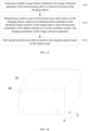
Images


Classifications
-
- B—PERFORMING OPERATIONS; TRANSPORTING
- B60—VEHICLES IN GENERAL
- B60L—PROPULSION OF ELECTRICALLY-PROPELLED VEHICLES; SUPPLYING ELECTRIC POWER FOR AUXILIARY EQUIPMENT OF ELECTRICALLY-PROPELLED VEHICLES; ELECTRODYNAMIC BRAKE SYSTEMS FOR VEHICLES IN GENERAL; MAGNETIC SUSPENSION OR LEVITATION FOR VEHICLES; MONITORING OPERATING VARIABLES OF ELECTRICALLY-PROPELLED VEHICLES; ELECTRIC SAFETY DEVICES FOR ELECTRICALLY-PROPELLED VEHICLES
- B60L53/00—Methods of charging batteries, specially adapted for electric vehicles; Charging stations or on-board charging equipment therefor; Exchange of energy storage elements in electric vehicles
- B60L53/30—Constructional details of charging stations
- B60L53/35—Means for automatic or assisted adjustment of the relative position of charging devices and vehicles
- B60L53/36—Means for automatic or assisted adjustment of the relative position of charging devices and vehicles by positioning the vehicle
-
- G—PHYSICS
- G05—CONTROLLING; REGULATING
- G05D—SYSTEMS FOR CONTROLLING OR REGULATING NON-ELECTRIC VARIABLES
- G05D1/00—Control of position, course, altitude or attitude of land, water, air or space vehicles, e.g. using automatic pilots
- G05D1/02—Control of position or course in two dimensions
- G05D1/021—Control of position or course in two dimensions specially adapted to land vehicles
- G05D1/0212—Control of position or course in two dimensions specially adapted to land vehicles with means for defining a desired trajectory
- G05D1/0225—Control of position or course in two dimensions specially adapted to land vehicles with means for defining a desired trajectory involving docking at a fixed facility, e.g. base station or loading bay
-
- A—HUMAN NECESSITIES
- A01—AGRICULTURE; FORESTRY; ANIMAL HUSBANDRY; HUNTING; TRAPPING; FISHING
- A01D—HARVESTING; MOWING
- A01D34/00—Mowers; Mowing apparatus of harvesters
- A01D34/006—Control or measuring arrangements
- A01D34/008—Control or measuring arrangements for automated or remotely controlled operation
-
- B—PERFORMING OPERATIONS; TRANSPORTING
- B60—VEHICLES IN GENERAL
- B60L—PROPULSION OF ELECTRICALLY-PROPELLED VEHICLES; SUPPLYING ELECTRIC POWER FOR AUXILIARY EQUIPMENT OF ELECTRICALLY-PROPELLED VEHICLES; ELECTRODYNAMIC BRAKE SYSTEMS FOR VEHICLES IN GENERAL; MAGNETIC SUSPENSION OR LEVITATION FOR VEHICLES; MONITORING OPERATING VARIABLES OF ELECTRICALLY-PROPELLED VEHICLES; ELECTRIC SAFETY DEVICES FOR ELECTRICALLY-PROPELLED VEHICLES
- B60L53/00—Methods of charging batteries, specially adapted for electric vehicles; Charging stations or on-board charging equipment therefor; Exchange of energy storage elements in electric vehicles
- B60L53/10—Methods of charging batteries, specially adapted for electric vehicles; Charging stations or on-board charging equipment therefor; Exchange of energy storage elements in electric vehicles characterised by the energy transfer between the charging station and the vehicle
- B60L53/14—Conductive energy transfer
- B60L53/16—Connectors, e.g. plugs or sockets, specially adapted for charging electric vehicles
-
- B—PERFORMING OPERATIONS; TRANSPORTING
- B60—VEHICLES IN GENERAL
- B60L—PROPULSION OF ELECTRICALLY-PROPELLED VEHICLES; SUPPLYING ELECTRIC POWER FOR AUXILIARY EQUIPMENT OF ELECTRICALLY-PROPELLED VEHICLES; ELECTRODYNAMIC BRAKE SYSTEMS FOR VEHICLES IN GENERAL; MAGNETIC SUSPENSION OR LEVITATION FOR VEHICLES; MONITORING OPERATING VARIABLES OF ELECTRICALLY-PROPELLED VEHICLES; ELECTRIC SAFETY DEVICES FOR ELECTRICALLY-PROPELLED VEHICLES
- B60L53/00—Methods of charging batteries, specially adapted for electric vehicles; Charging stations or on-board charging equipment therefor; Exchange of energy storage elements in electric vehicles
- B60L53/30—Constructional details of charging stations
-
- B—PERFORMING OPERATIONS; TRANSPORTING
- B60—VEHICLES IN GENERAL
- B60L—PROPULSION OF ELECTRICALLY-PROPELLED VEHICLES; SUPPLYING ELECTRIC POWER FOR AUXILIARY EQUIPMENT OF ELECTRICALLY-PROPELLED VEHICLES; ELECTRODYNAMIC BRAKE SYSTEMS FOR VEHICLES IN GENERAL; MAGNETIC SUSPENSION OR LEVITATION FOR VEHICLES; MONITORING OPERATING VARIABLES OF ELECTRICALLY-PROPELLED VEHICLES; ELECTRIC SAFETY DEVICES FOR ELECTRICALLY-PROPELLED VEHICLES
- B60L53/00—Methods of charging batteries, specially adapted for electric vehicles; Charging stations or on-board charging equipment therefor; Exchange of energy storage elements in electric vehicles
- B60L53/60—Monitoring or controlling charging stations
- B60L53/66—Data transfer between charging stations and vehicles
-
- G—PHYSICS
- G05—CONTROLLING; REGULATING
- G05D—SYSTEMS FOR CONTROLLING OR REGULATING NON-ELECTRIC VARIABLES
- G05D1/00—Control of position, course, altitude or attitude of land, water, air or space vehicles, e.g. using automatic pilots
- G05D1/02—Control of position or course in two dimensions
- G05D1/021—Control of position or course in two dimensions specially adapted to land vehicles
- G05D1/0231—Control of position or course in two dimensions specially adapted to land vehicles using optical position detecting means
- G05D1/0234—Control of position or course in two dimensions specially adapted to land vehicles using optical position detecting means using optical markers or beacons
-
- G—PHYSICS
- G05—CONTROLLING; REGULATING
- G05D—SYSTEMS FOR CONTROLLING OR REGULATING NON-ELECTRIC VARIABLES
- G05D1/00—Control of position, course, altitude or attitude of land, water, air or space vehicles, e.g. using automatic pilots
- G05D1/02—Control of position or course in two dimensions
- G05D1/021—Control of position or course in two dimensions specially adapted to land vehicles
- G05D1/0231—Control of position or course in two dimensions specially adapted to land vehicles using optical position detecting means
- G05D1/0246—Control of position or course in two dimensions specially adapted to land vehicles using optical position detecting means using a video camera in combination with image processing means
-
- G—PHYSICS
- G05—CONTROLLING; REGULATING
- G05D—SYSTEMS FOR CONTROLLING OR REGULATING NON-ELECTRIC VARIABLES
- G05D1/00—Control of position, course, altitude or attitude of land, water, air or space vehicles, e.g. using automatic pilots
- G05D1/20—Control system inputs
- G05D1/24—Arrangements for determining position or orientation
- G05D1/247—Arrangements for determining position or orientation using signals provided by artificial sources external to the vehicle, e.g. navigation beacons
-
- G—PHYSICS
- G05—CONTROLLING; REGULATING
- G05D—SYSTEMS FOR CONTROLLING OR REGULATING NON-ELECTRIC VARIABLES
- G05D1/00—Control of position, course, altitude or attitude of land, water, air or space vehicles, e.g. using automatic pilots
- G05D1/60—Intended control result
- G05D1/656—Interaction with payloads or external entities
- G05D1/661—Docking at a base station
-
- A—HUMAN NECESSITIES
- A01—AGRICULTURE; FORESTRY; ANIMAL HUSBANDRY; HUNTING; TRAPPING; FISHING
- A01D—HARVESTING; MOWING
- A01D2101/00—Lawn-mowers
-
- B—PERFORMING OPERATIONS; TRANSPORTING
- B60—VEHICLES IN GENERAL
- B60L—PROPULSION OF ELECTRICALLY-PROPELLED VEHICLES; SUPPLYING ELECTRIC POWER FOR AUXILIARY EQUIPMENT OF ELECTRICALLY-PROPELLED VEHICLES; ELECTRODYNAMIC BRAKE SYSTEMS FOR VEHICLES IN GENERAL; MAGNETIC SUSPENSION OR LEVITATION FOR VEHICLES; MONITORING OPERATING VARIABLES OF ELECTRICALLY-PROPELLED VEHICLES; ELECTRIC SAFETY DEVICES FOR ELECTRICALLY-PROPELLED VEHICLES
- B60L2200/00—Type of vehicles
- B60L2200/22—Microcars, e.g. golf cars
-
- B—PERFORMING OPERATIONS; TRANSPORTING
- B60—VEHICLES IN GENERAL
- B60L—PROPULSION OF ELECTRICALLY-PROPELLED VEHICLES; SUPPLYING ELECTRIC POWER FOR AUXILIARY EQUIPMENT OF ELECTRICALLY-PROPELLED VEHICLES; ELECTRODYNAMIC BRAKE SYSTEMS FOR VEHICLES IN GENERAL; MAGNETIC SUSPENSION OR LEVITATION FOR VEHICLES; MONITORING OPERATING VARIABLES OF ELECTRICALLY-PROPELLED VEHICLES; ELECTRIC SAFETY DEVICES FOR ELECTRICALLY-PROPELLED VEHICLES
- B60L2200/00—Type of vehicles
- B60L2200/40—Working vehicles
-
- B—PERFORMING OPERATIONS; TRANSPORTING
- B60—VEHICLES IN GENERAL
- B60L—PROPULSION OF ELECTRICALLY-PROPELLED VEHICLES; SUPPLYING ELECTRIC POWER FOR AUXILIARY EQUIPMENT OF ELECTRICALLY-PROPELLED VEHICLES; ELECTRODYNAMIC BRAKE SYSTEMS FOR VEHICLES IN GENERAL; MAGNETIC SUSPENSION OR LEVITATION FOR VEHICLES; MONITORING OPERATING VARIABLES OF ELECTRICALLY-PROPELLED VEHICLES; ELECTRIC SAFETY DEVICES FOR ELECTRICALLY-PROPELLED VEHICLES
- B60L2240/00—Control parameters of input or output; Target parameters
- B60L2240/60—Navigation input
- B60L2240/62—Vehicle position
-
- B—PERFORMING OPERATIONS; TRANSPORTING
- B60—VEHICLES IN GENERAL
- B60L—PROPULSION OF ELECTRICALLY-PROPELLED VEHICLES; SUPPLYING ELECTRIC POWER FOR AUXILIARY EQUIPMENT OF ELECTRICALLY-PROPELLED VEHICLES; ELECTRODYNAMIC BRAKE SYSTEMS FOR VEHICLES IN GENERAL; MAGNETIC SUSPENSION OR LEVITATION FOR VEHICLES; MONITORING OPERATING VARIABLES OF ELECTRICALLY-PROPELLED VEHICLES; ELECTRIC SAFETY DEVICES FOR ELECTRICALLY-PROPELLED VEHICLES
- B60L2260/00—Operating Modes
- B60L2260/20—Drive modes; Transition between modes
- B60L2260/32—Auto pilot mode
-
- Y—GENERAL TAGGING OF NEW TECHNOLOGICAL DEVELOPMENTS; GENERAL TAGGING OF CROSS-SECTIONAL TECHNOLOGIES SPANNING OVER SEVERAL SECTIONS OF THE IPC; TECHNICAL SUBJECTS COVERED BY FORMER USPC CROSS-REFERENCE ART COLLECTIONS [XRACs] AND DIGESTS
- Y02—TECHNOLOGIES OR APPLICATIONS FOR MITIGATION OR ADAPTATION AGAINST CLIMATE CHANGE
- Y02T—CLIMATE CHANGE MITIGATION TECHNOLOGIES RELATED TO TRANSPORTATION
- Y02T10/00—Road transport of goods or passengers
- Y02T10/60—Other road transportation technologies with climate change mitigation effect
- Y02T10/70—Energy storage systems for electromobility, e.g. batteries
-
- Y—GENERAL TAGGING OF NEW TECHNOLOGICAL DEVELOPMENTS; GENERAL TAGGING OF CROSS-SECTIONAL TECHNOLOGIES SPANNING OVER SEVERAL SECTIONS OF THE IPC; TECHNICAL SUBJECTS COVERED BY FORMER USPC CROSS-REFERENCE ART COLLECTIONS [XRACs] AND DIGESTS
- Y02—TECHNOLOGIES OR APPLICATIONS FOR MITIGATION OR ADAPTATION AGAINST CLIMATE CHANGE
- Y02T—CLIMATE CHANGE MITIGATION TECHNOLOGIES RELATED TO TRANSPORTATION
- Y02T10/00—Road transport of goods or passengers
- Y02T10/60—Other road transportation technologies with climate change mitigation effect
- Y02T10/7072—Electromobility specific charging systems or methods for batteries, ultracapacitors, supercapacitors or double-layer capacitors
Definitions
- Embodiments of the present disclosure relate to the technical field of gardening equipment, in particular to a charging station, a charging station system, a method for returning to a charging station and a lawnmowing robot.
- Lawnmowing robots can automatically mow lawns, etc., thereby reducing labor time consumption. Lawnmowing robots may follow input instructions to accomplish the act of returning to a charging station unattended, thus reducing the burden on users and saving time.
- lawnmowing robot station-returning technologies are based on methods such as GPS positioning, guiding wire guidance, or virtual boundary patrol.
- lawnmowing robots usually return to the station using infrared, ultrasonic induction station-returning technology or a virtual boundary guidance method based on map building. This infrared, ultrasonic station-returning has a great chance of false touch, and is seriously affected by environmental noise.
- US20220047138A1 is directed to Systems, devices, and methods for docking a mobile robot to a dock using distinct visual fiducial markers on the dock are disclosed.
- a mobile robot system is provided that includes a dock and a mobile cleaning robot.
- the dock includes a first fiducial marker in a first plane on the dock and second one or more fiducial markers in a second plane different from the first plane.
- the mobile cleaning robot includes a visual system to detect the first and the second one or more fiducial markers, and a controller circuit to recognize the dock, and to determine a pose or heading direction of the mobile cleaning robot based on the detected first and the second one or more fiducial markers.
- the mobile drive system can adjust its heading direction, and drive to the dock according to the adjusted heading direction.
- US2019/092183A1 discloses a An electrical charging station for charging an autonomous robot having a battery.
- the charging station includes a first charging member configured to receive a second charging member on the autonomous robot when the autonomous robot is docked with the charging station.
- There is a communications device configured to receive from the autonomous robot an identifier indicative of a type of battery on the autonomous robot.
- US2004/012362A1 discloses an electrical charging system including a robot apparatus and an electrical charging device.
- the robot apparatus has a built-in a power supply unit for driving and adapted for acting autonomously responsive to an inner state.
- the electrical charging device electrically charges the power supply unit, and the electrical charging device includes a marker provided at a predetermined position.
- the robot apparatus includes imaging means for imaging a surrounding state; storage means having the information on the position of the marker pre-stored therein; position vector calculating means for calculating the distance and the direction to the marker from the information on the marker position stored in the storage means and from an image including the marker position, photographed by the imaging means; operation controlling means for performing control for causing movement of the robot apparatus towards the electrical charging device depending on the distance and the direction to the marker calculated by the position vector calculating means.
- embodiments of the present disclosure provide a charging station, a charging station system, a method and apparatus for returning to a charging station and a lawnmowing robot, to at least partially solve the above problems.
- a charging station, a charging station system, a method for returning to a charging station and a lawnmowing robot as defined in the claims are provided.
- One or more embodiments of the present disclosure provide a charging station, the charging station is provided with a marking component or a plurality of feature markers preset on the charging station.
- the marking component includes a first marking component and a second marking component, and the first marking component and the second marking component have different distribution surfaces on the charging station, and the marking component is used for indicating a position of the charging station so that a lawnmowing robot is capable of docking with the charging station for charging.
- a distribution surface of at least two of the plurality of feature markers is different from a distribution surface of the remaining feature markers , and the feature markers are used for image identification by a lawnmowing robot to enable the lawnmowing robot to dock with the charging station for charging.
- a charging station system including the charging station according to any one of the above aspects and a marking apparatus, the marking apparatus is provided with a fourth marking component, and the fourth marking component is used to assist in determining a position of the charging station.
- a method for returning to a charging station is provided, the method being used for directing a lawnmowing robot to return to a charging station, the lawnmowing robot being configured with an image collection apparatus, the charging station being distributed with feature markers, and the method including: acquiring available image frames collected by the image collection apparatus of the lawnmowing robot in a front area of the charging station, the number of feature markers identified in the image frames being greater than or equal to N, and the N being a positive integer greater than or equal to 3; determining a relative pose of the lawnmowing robot relative to the charging station, based on two-dimensional coordinates of the identified feature markers in the image frames, three-dimensional coordinates of the feature markers in a global coordinate system, and imaging parameters of the image collection apparatus; and driving the lawnmowing robot to return to the charging station based on the relative pose.
- a lawnmowing robot is provided, the lawnmowing robot being configured with an image collection apparatus, the lawnmowing robot including a controller, and the controller being configured to perform the method described above.
- the method may accurately determine the relative pose between the lawnmowing robot and the charging station, and then direct the lawnmowing robot to return to the station accurately based on the relative pose.
- the use of the feature markers for positioning ensures positioning accuracy, and visual imaging may not be interfered by noise from other electromagnetic waves and signals in an environment, ensuring accuracy and reliability, there is no need to lay additional guiding wires, at the same time, the method overcomes the defect of GPS positioning error and fully ensures the accuracy of station-returning.
- the lawn mower can acquire pose information of the feature markers distributed in the marking component through its own image identification, so that relative pose information between the charging station and the lawn mower may be determined for path planning, enabling the lawn mower to realize station-returning and charging.
- the cost is low and the structure is simple and easy to install and dismantle, since only the feature markers need to be provided on the charging station.
- the lawnmowing robot may be an automatic lawn mower, which includes several major parts such as a main body, an image collection apparatus (which may also be called a vision collection apparatus), a navigation position estimation apparatus, a vision position estimation apparatus, and an autonomous moving apparatus.
- a main body an image collection apparatus (which may also be called a vision collection apparatus), a navigation position estimation apparatus, a vision position estimation apparatus, and an autonomous moving apparatus.
- the main body includes a housing and a lawnmowing blade assembly, etc.
- the lawnmowing blade assembly is configured to mow grass in the lawn so that the grass is at an appropriate height.
- the autonomous moving apparatus includes a drive wheel, a drive motor and a motor controller, etc.
- the motor controller is connected to the drive motor to control rotation of the drive motor and then drive the drive wheel to move, so as to realize moving forward, backward, steering, etc. of the lawnmowing robot.
- the image collection apparatus may include a video camera, a camera, and so on. Imaging parameters of the image collection apparatus may be different for different structures, for example, the imaging parameters include aperture, focal length, optical axis, and so on.
- the navigation position estimation apparatus is configured to position the lawnmowing robot, and then drive the lawnmowing robot to move based on a positioning result.
- the vision position estimation apparatus may be configured to process image frames collected by the image collection apparatus, then estimate a relative pose of the lawnmowing robot relative to the charging station based on the image frames, so as to navigate the lawnmowing robot and drive it to move based on the relative pose. It should be noted that the vision position estimation apparatus may be a stand-alone chip having computing power or a common chip shared with other apparatuses, which is not limited in this regard.
- a charging station (marking number 10 in FIG. 1B ) is provided with Q feature markers (marking number 20 in FIG. 1B ), the Q is greater than or equal to 2 and is a positive integer.
- the feature markers may be any appropriate pattern, shape or structure, etc., capable of marking, which is not limited in this regard.
- the feature markers may be triangular bumps, or dots, rectangular patterns, two-dimensional codes or line segments, arcs, etc. provided on the charging station, further examples will be omitted herein.
- the maximum distance of projection of the Q feature markers on each of the coordinate axis is greater than or equal to a distance threshold (the distance threshold may be determined based on a required positioning identification accuracy).
- a distance threshold may be determined based on a required positioning identification accuracy.
- a Z-axis is a forward direction of the lawnmowing robot, and in a conventional flat ground environment, docking the lawnmowing robot in a charging station depends more on transformation of a yaw angle (i.e., an angle of rotation around a Y-axis), i.e., the greater a lateral distance between the feature markers on the charging station, when the relative pose of the lawnmowing robot relative to the charging station is changed, the greater an absolute distance of position change of the feature markers distributed on an imaging plane, so that an anti-interference ability is stronger.
- a pitch angle i.e., an angle of rotation around an X-axis
- a distribution surface of at least two of the feature markers in the Q feature markers is different from a distribution surface of the remaining feature markers, i.e., the plurality of feature markers provided on the charging station are on at least two different distribution surfaces, so that differentiation of the feature markers in a Z-axis direction is realized, and it may be determined after comparative experiments that: a charging station A, where all feature markers are located on the same distribution surface, is less resistant to noise than a charging station B, where at least two feature markers and the remaining feature markers are located on different distribution surfaces. For the same number of tests, the charging station A is unable to calculate the relative pose and an accuracy of the calculated relative pose is worse than that of the charging station B.
- the anti-interference ability and an anti-sensitivity ability of the lawnmowing robot for relative pose identification may be improved.
- the distribution method exemplified in this embodiment of the present disclosure is a preferred method, in other embodiments, the feature markers may use other distribution methods, as long as the relative pose can be calculated.
- Step S102 acquiring available image frames collected by the image collection apparatus of the lawnmowing robot in a front area of the charging station.
- the image collection apparatus collects the image frames of the environment during movement of the lawnmowing robot, and a plurality of image frames at different moments form a sequence of image frames (which may also be called a video). Since the pose of the lawnmowing robot is different at different moments, contents contained in the image frames may be different, some image frames may contain feature markers, and some image frames may not contain feature markers.
- the front area of the charging station includes a sector area corresponding to the charging station, the sector area is located in front of the charging station, and a radius of the sector area takes a value greater than 0 and less than M, and the M is a positive integer.
- the value of the M may be determined based on the imaging parameters of the image collection apparatus, sizes of the feature markers, etc., which is not limited in this regard.
- the front area of the charging station may be a sector area with a radius of 2 meters and an angle of 120°.
- a shape, dimension, etc. of the front area of the charging station may be appropriately selected, which is not limited in this regard.
- step S102 may be implemented through the following sub-steps: Sub-step S1021: acquiring a navigation pose of the lawnmowing robot at a current moment.
- the navigation estimation apparatus of the lawnmowing robot may locate the navigation pose of the lawnmowing robot.
- Sub-step S1022 determining whether the lawnmowing robot is in the front area of the charging station, based on the navigation pose and a preset pose of the charging station.
- the front area of the charging station may be determined, then based on position information in the navigation pose, it may be determined whether the lawnmowing robot is in the front area of the charging station.
- sub-step S1023 may be performed; otherwise, the lawnmowing robot needs to be driven to move into the front area of the charging station first, so sub-step S1025 may be performed.
- Sub-step S1023 determining whether the available image frames are present in the a sequence of image frames collected by the image collection apparatus, if the lawnmowing robot is in the front area of the charging station.
- image identification is performed on each image frame in the a sequence of image frames using a trained robot learning model to identify feature markers therefrom, and determine whether the image frames are the available image frames based on the number of feature markers identified.
- Sub-step S1024 may be performed; otherwise, sub-step S1026 may be performed.
- Sub-step S1024 using the present available image frames as the acquired available image frames, if there are available image frames.
- Step S104 may be performed after obtaining the available image frames.
- Sub-step S1025 driving the lawnmowing robot to move into the front area of the charging station based on the navigation pose, if the lawnmowing robot is not in the front area of the charging station, and returning to the step of acquiring a navigation pose of the lawnmowing robot at a current moment to continue execution.
- the navigation position estimation apparatus may direct the lawnmowing robot to move based on the navigation pose, then return to sub-step S 1021 for execution, and so on until the lawnmowing robot moves into the front area of the charging station. In this way, the lawnmowing robot enters a station-returning mode when moved into the front area of the charging station and a sufficient number of feature markers can be collected.
- Sub-step S1026 adjusting at least one of a position and a pose of the lawnmowing robot, and acquiring a new a sequence of image frames, if the available image frames are not present, and returning to the step of determining whether the available image frames are present in the a sequence of image frames collected by the image collection apparatus to continue execution.
- the lawnmowing robot in adjusting at least one of the position and the pose of the lawnmowing robot, the lawnmowing robot is adjusted to a new navigation pose, and the lawnmowing robot is outside the front area of the charging station when in the new navigation pose; the lawnmowing robot is driven into the front area of the charging station based on the new navigation pose, and the image collection apparatus collects a plurality of image frames during movement of the lawnmowing robot to form the a sequence of image frames.
- the lawnmowing robot may be driven to exit the front area of the charging station, then enter the front area of the charging station again at a different angle, then collect image frames, and return to determine whether the available image frames are present in the a sequence of image frames collected by the image collection apparatus.
- the lawnmowing robot may randomly select a direction to drive out of the front area of the charging station, drive in again at a different angle, detect feature markers on the charging station again, and so on until a sufficient number of feature markers are detected, then enter the station-returning mode.
- Step S104 determining a relative pose of the lawnmowing robot relative to the charging station, based on two-dimensional coordinates of the identified feature markers in the image frames, three-dimensional coordinates of the feature markers in a global coordinate system, and imaging parameters of the image collection apparatus.
- the vision position estimation apparatus of the robot continuously updates the relative pose of the lawnmowing robot and the charging station by detecting and matching the image frames, and then directs the lawnmowing robot to dock in the station to complete docking with the charging station.
- a method for detecting the image frames may be: identifying the image frames using a trained neural network model to detect feature markers in the image frames, and determining two-dimensional coordinates of the feature markers in the image frames.
- Different neural network models may be trained for different feature markers to detect the feature markers in the image frames.
- the relative pose at the current moment may be determined.
- a process for calculating the relative pose is, for example, as follows: based on the two-dimensional coordinates and the imaging parameters of the image collection apparatus, the two-dimensional coordinates may be converted into three-dimensional coordinates in a coordinate system of the image collection apparatus, and then a mapping relationship between the coordinate system of the image collection apparatus and the global coordinate system may be determined based on the three-dimensional coordinates of the feature markers in the coordinate system of the image collection apparatus and its three-dimensional coordinates in the global coordinate system, and the mapping relationship is the relative pose.
- Step S106 driving the lawnmowing robot to return to the charging station based on the relative pose.
- the pose of the lawnmowing robot may be adjusted based on the relative pose, so that the lawnmowing robot is facing towards the charging station, thereby realizing station-returning of the lawnmowing robot.
- the ability of the lawnmowing robot to quickly and accurately return to the station is greatly influenced by an accuracy of identifying the two-dimensional coordinates of the feature markers in the image frames, and since the image frames are collected during the movement of the lawnmowing robot, they are inevitably affected by motion blurring.
- the image collection apparatus collects the image frames
- exposure time of the image frames is positively correlated with a relative distance when a light intensity of an ambient light is fixed, and the relative distance is a distance between the lawnmowing robot and the charging station.
- the exposure time of the image collection apparatus is determined based on the light intensity of the ambient light, the brighter the ambient light the shorter the exposure time, and the shorter the exposure time, the less motion blurring is generated.
- the distance between the lawnmowing robot and the charging station is less than or equal to Y (Y is a positive integer and less than X)
- Y is a positive integer and less than X
- the exposure time of the image collection apparatus decreases with the distance until the distance reaches a distance threshold, which may sufficiently reduce motion blurring.
- the exposure time remains constant when the light intensity and the distance are the same.
- the exposure time T decreases by a * z ms.
- a may be set appropriately as needed.
- the exposure time T increases or decreases accordingly.
- the effects of light intensity and distance on the exposure time are independent of each other.
- data enhancement technology may be used to improve the accuracy of identifying feature markers, thus avoiding miss detection to improve robustness.
- this embodiment may accurately determine the relative pose between the lawnmowing robot and the charging station, and then direct the lawnmowing robot to return to the station accurately based on the relative pose.
- the use of the feature markers for positioning ensures positioning accuracy, and visual imaging may not be interfered by noise from other electromagnetic waves and signals in an environment, ensuring accuracy and reliability, there is no need to lay additional guiding wires, at the same time, it overcomes the defect of GPS positioning error and fully ensures the accuracy of station-returning.
- the lawnmowing robot in any position in the work area may accurately return to the station and charge from any direction.
- stable station-docking and charging may be realized by using the characteristic that visual information such as image frames become more accurate with proximity.
- feature marker distribution has better robustness and better resistance to detection sensitivity, and the problem of motion blurring, which is difficult to deal with in a vision solution, is also solved by adjusting the exposure time based on the distance.
- FIG. 2 illustrating a structural block diagram of an apparatus for returning to a charging station provided in Embodiment 2.
- the apparatus is configured to direct a lawnmowing robot to return to a charging station, the lawnmowing robot is configured with an image collection apparatus, the charging station is distributed with feature markers, and the apparatus includes:
- the front area of the charging station includes a sector area corresponding to the charging station, the sector area is located in front of the charging station, and a radius of the sector area takes a value greater than 0 and less than M, and the M is a positive integer.
- the acquisition module 202 is configured to acquire a navigation pose of the lawnmowing robot at a current moment; determine whether the lawnmowing robot is in the front area of the charging station, based on the navigation pose and a preset pose of the charging station; determine whether the available image frames are present in a sequence of image frames collected by the image collection apparatus, if the lawnmowing robot is in the front area of the charging station; and use the present available image frames as the acquired available image frames, if there are available image frames.
- the acquisition module 202 is further configured to adjust at least one of a position and a pose of the lawnmowing robot, and acquire a new a sequence of image frames, if the available image frames are not present, and return to the step of determining whether the available image frames are present in the a sequence of image frames collected by the image collection apparatus to continue execution.
- the acquisition module 202 is configured to adjust the lawnmowing robot to a new navigation pose, when adjusting at least one of a position and a pose of the lawnmowing robot, the lawnmowing robot being located outside the front area of the charging station when in the new navigation pose; and drive the lawnmowing robot into the front area of the charging station based on the new navigation pose, the image collection apparatus collecting a plurality of image frames during movement of the lawnmowing robot to form the a sequence of image frames.
- the acquisition module 202 is further configured to drive the lawnmowing robot to move into the front area of the charging station based on the navigation pose, if the lawnmowing robot is not in the front area of the charging station, and return to the step of acquiring a navigation pose of the lawnmowing robot at a current moment to continue execution.
- the charging station is provided with Q feature markers, the Q is greater than or equal to 2 and is a positive integer, for each coordinate axis of the global coordinate system, the maximum distance of projection of the Q feature markers on each of the coordinate axis is greater than or equal to a distance threshold.
- a distribution surface of at least two of the feature markers in the Q feature markers is different from a distribution surface of the remaining feature markers.
- exposure time of the image frames is positively correlated with a relative distance when a light intensity of an ambient light is fixed, and the relative distance is a distance between the lawnmowing robot and the charging station.
- the apparatus is capable of achieving corresponding effects of the corresponding method, therefore detailed description thereof will be omitted.
- a lawnmowing robot is provided, the lawnmowing robot is configured with an image collection apparatus, including a controller, and the controller is configured to perform the foregoing method.
- the controller may implement the operations corresponding to the foregoing method and achieve corresponding effects, detailed description thereof will be omitted.
- a computer storage medium stores a computer program therein, the computer program, when executed by a processor, implements the method described above.
- the program may implement the operations corresponding to the foregoing method and achieve corresponding effects, detailed description thereof will be omitted.
- a charging station 10 is provided, the charging station 10 is provided with Q feature markers 20, a distribution surface of at least two of the feature markers 20 in the Q feature markers 20 is different from a distribution surface of the remaining feature markers 20, and the Q is greater than or equal to 2 and is a positive integer.
- the charging station is provided with Q feature markers 20, the distribution surface of at least two of the feature markers 20 in the Q feature markers 20 is different from the distribution surface of the remaining feature markers 20, and the Q is greater than or equal to 2 and is a positive integer.
- the lawnmowing robot can acquire pose information of the feature markers 20 through its own image identification, so that relative pose information between the charging station and the lawnmowing robot may be determined for path planning, enabling the lawnmowing robot to realize station-returning and charging.
- the cost is low and the structure is simple and easy to install and dismantle, since only the feature markers 20 need to be provided on the charging station.
- the distribution surface of at least two of the plurality of feature markers 20 being different from the distribution surface of the remaining feature markers 20, it can improve the accuracy of image identification by the lawnmowing robot to calculate the relative pose information of the charging station.
- the charging station (marking number 10 in FIG. 1B ) is provided with Q feature markers 20 (marking number 20 in FIG. 1B ), the Q is greater than or equal to 2 and is a positive integer.
- the feature markers 20 may be any appropriate pattern, shape or structure, etc., capable of marking, which is not limited in this regard.
- the feature markers 20 may be triangular bumps, or dots, rectangular patterns, two-dimensional codes or line segments, arcs, etc. provided on the charging station, further examples will be omitted herein.
- the maximum distance of projection of the Q feature markers 20 on each of the coordinate axis is greater than or equal to a distance threshold (the distance threshold may be determined based on a required positioning identification accuracy).
- a distance threshold may be determined based on a required positioning identification accuracy.
- a Z-axis is a forward direction of the lawnmowing robot, and in a conventional flat ground environment, docking the lawnmowing robot in a charging station depends more on transformation of a yaw angle (i.e., an angle of rotation around a Y-axis), i.e., the greater a lateral distance between the feature markers 20 on the charging station, when the relative pose of the lawnmowing robot relative to the charging station is changed, the greater an absolute distance of position change of the feature markers 20 distributed on an imaging plane, so that an anti-interference ability is stronger.
- a pitch angle i.e., an angle of rotation around an X-axis
- a distribution surface of at least two of the feature markers 20 in the Q feature markers 20 is different from a distribution surface of remaining feature markers 20 of the feature markers 20, i.e., the plurality of feature markers 20 provided on the charging station are on at least two different distribution surfaces, so that differentiation of the feature markers 20 in a Z-axis direction is realized, and it may be determined after comparative experiments that: a charging station A, where all feature markers 20 are located on the same distribution surface, is less resistant to noise than a charging station B, where at least two feature markers 20 and the remaining feature markers 20 are located on different distribution surfaces. For the same number of tests, the charging station A is unable to calculate the relative pose and an accuracy of the calculated relative pose is worse than that of the charging station B.
- the anti-interference ability and an anti-sensitivity ability of the lawnmowing robot for relative pose identification may be improved.
- the distribution method exemplified in this embodiment of the present disclosure is a preferred method, in other embodiments, the feature markers 20 may use other distribution methods, as long as the relative pose can be calculated.
- a charging station 10 is provided, for the purpose of description and understanding, an overall structure of the charging station 10 is briefly described as follows before describing the charging station of this embodiment.
- the charging station 10 may include a charging station main body 1 and a charging assembly 3.
- the charging station main body 1 includes a top cover 12, a charging station body 11 and a base plate 13, and the charging assembly 3 is mounted on a side of the charging station body 11, where the top cover 12 is connected to an upper end of the charging station body 11 and the base plate 13 is connected to a lower end of the charging station body 11.
- the feature markers 20 are marking points, and the marking points refer to points having abstract meaning, which may be explicit marking points, for example, end points of line segments, corner points of shapes, corner points of two-dimensional codes, etc., or implicit marking points for semantic classes, for example, a midpoint of intersection of different surfaces, semantic information of the marker itself such as the wrist of a human-shaped marker, a center point of the densest grass of a grass marker, etc.
- the marking points may be points on a surface, or may be convex points or concave points on that surface.
- the feature markers 20 in this embodiment refers to explicit marking points on the charging station 10, which may be marking points of the charging station 10 itself, such as end points of edges on the surface of the charging station 10, or marking points designed according to requirements of an image identification algorithm of the lawnmowing robot.
- marking components 2 of different shapes are provided on the charging station 10
- the feature markers 20 are the corner points of the shapes of the marking components 2, etc., which is not limited in this regard in this embodiment.
- An image collection apparatus of the lawnmowing robot collects available image frames in the front area of the charging station 10 and identifies the preset feature markers 20 on the surface of the charging station 10 from the image frames based on the preset identification algorithm, where the preset feature markers 20 are marking points on the charging station 10 preset based on the preset identification algorithm. Based on two-dimensional coordinates of the identified feature markers 20 in the image frames, three-dimensional coordinates of the feature markers 20 in a global coordinate system, and imaging parameters of the image collection apparatus, a relative pose of the lawnmowing robot relative to the charging station 10 is determined; and the lawnmowing robot is driven to return to the charging station 10 based on the relative pose.
- the charging station 10 is provided with a plurality of feature markers 20, a distribution surface of at least two of the feature markers 20 in the plurality of feature markers 20 is different from a distribution surface of the remaining feature markers 20, i.e., the plurality of feature markers 20 provided on the charging station 10 are on at least two different distribution surfaces, so that differentiation of the feature markers 20 in a Z-axis direction is realized, and it may be determined after comparative experiments that: a charging station A, where all feature markers 20 are located on the same distribution surface, is less resistant to noise than a charging station B, where at least two feature markers 20 and the remaining feature markers 20 are located on different distribution surfaces. For the same number of tests, the charging station A is unable to calculate the relative pose and an accuracy of the calculated relative pose is worse than that of the charging station B.
- the lawnmowing robot can acquire pose information of the feature markers 20 through its own image identification, so that relative pose information between the charging station 10 and the lawnmowing robot may be determined for path planning, enabling the lawnmowing robot to realize station-returning and charging.
- the cost is low and the structure is simple and easy to install and dismantle, since only the feature markers 20 need to be provided on the surface of the charging station.
- the distribution surface of at least two of the plurality of feature markers 20 being different from the distribution surface of the remaining feature markers 20, it can improve the accuracy of image identification by the lawnmowing robot to calculate the relative pose information of the charging station 10.
- a marking component 2 is provided on the surface of the charging station 10, the marking component 2 includes a first marking component 211 and a second marking component 212, and the first marking component 211 and the second marking component 212 have different distribution surfaces on the charging station 10. At least two feature markers 20 are distributed on the marking component 2.
- the number of the first marking component 211 and the second marking component 212 may be greater than or equal to 1 and is a positive integer, respectively.
- the marking component 2 may have different shapes, such as rectangular, triangular, circular or L-shaped.
- the first marking component 211 and the second marking component 212 may use the same shape of the marking components 2 or different shapes of the marking components 2.
- the first marking component 211 may use 4 L-shaped marking components 2 and the second marking component 212 may use 1 strip-shaped marking component 2, which is not limited in this regard in this embodiment.
- Each marking component 2 may be of a single shape or a combination of a plurality different shapes.
- the marking component 2 may be flat, such as a sticker, or may be three-dimensional, such as a plastic reflective assembly.
- the number of feature markers 20 on each marking component 2 may be greater than or equal to 2 and is a positive integer, and distribution locations of the feature markers 20 on different shapes of the marking components 2 are different, which may be preset based on the image identification algorithm of the lawnmowing robot, e.g., the feature markers 20 on a rectangular marking component 2 may be provided at least two of the four corner points, and the feature markers 20 on a L-shaped marking component 2 may be provided at least two of the four end points, etc.
- the feature markers 20 have more optional distribution locations on the charging station 10, and the number of feature markers 20 can be provided is more, thereby improving the accuracy of image identification calculations by the lawnmowing robot; in addition, by providing the marking component 2, the location and number of feature distributions may be set based on the image identification algorithm or hardware specifications used by the lawnmowing robot, enabling adaptation to a wider range of robot products.
- the first marking component 211 is located on a first distribution surface 41 of the charging station 10
- the second marking component 212 is located on a second distribution surface 42 of the charging station 10
- an angle is formed between a normal of the first distribution surface 41 and a normal of the second distribution surface 42, and the angle is not equal to 0 degree; or the normal of the first distribution surface 41 is parallel to the normal of the second distribution surface 42, and the first distribution surface 41 and the second distribution surface 42 are spaced apart in the direction of the normal.
- the first distribution surface 41 may be a first side of the charging station 10 provided with a charging structure 3, and the second distribution surface 42 may be a side on the charging station 10 that connects to the first side, or a side, an upper surface or a lower surface on the charging structure 3; the normal of the two (the dotted lines shown in the figure) form an angle A, and the angle A is not equal to 0 degree, then the first distribution surface 41 and the second distribution surface 42 are different distribution surfaces.
- the first distribution surface 41 may be the first side of the charging station 10 provided with the charging structure 3
- the second distribution surface 42 may be a side opposite to the first side on the charging station 10 or a front-end surface of the charging structure 3.
- the normal of the two are parallel, but they are spaced apart in the normal direction.
- the first distribution surface 41 and the second distribution surface 42 are different distribution surfaces. In this specific implementation, by determining a positional relationship between the distribution surfaces corresponding to the first marking component 211 and the second marking component 212, it may be determined that the first marking component 211 and the second marking component 212 are located on different distribution surfaces.
- the first distribution surface 41 and the second distribution surface 42 may include planes and curved surfaces.
- the first distribution surface 41 and the second distribution surface 42 may be sides of the charging station 10, or edges where the two sides intersect, etc. It should be noted that when the marking component 2 is provided on a curved surface, the normal of the location of the marking component 2 is used as the normal of the distribution surface of the marking component 2. When a plurality of feature markers 20 on distribution surfaces with large differences in curvature are collected simultaneously, the final calculated relative pose information of the charging station 10 and the lawnmowing robot is more accurate.
- the charging station 10 includes the charging station body 11 and the charging structure 3, the charging structure 3 is mounted on a first side of the charging station body 11, the second marking component 212 is provided on the charging structure 3, and the first marking component 211 is provided on the first side of the charging station body 11 where the charging structure 3 is mounted.
- one end of the charging structure 3 is mounted on the first side of the charging station body 11 and the other end of the charging structure 3 extends out of the charging station body 11, and the charging structure 3 is used to connect to a charging port of the lawnmowing robot to charge the lawnmowing robot.
- the second marking component 212 is provided on the charging structure 3, and the first marking component 211 is provided on the first side of the charging station body 11 where the charging structure 3 is mounted.
- the first marking component 211 may use 4 L-shaped marking components 2 and the second marking component 212 may use 1 strip-shaped marking component 2.
- the strip-shaped marking component is mounted on one end of the charging structure 3 extending out of the charging station body 11, and the 4 L-shaped marking components are mounted on the first side of the charging station body 11 where the charging structure 3 is mounted.
- the 4 L-shaped marking components 2 surround the strip-shaped marking component 2, which have both aesthetics and functionality of the feature markers 20.
- the second marking component 212 on the charging structure 3 and the first marking component 211 on the side of the charging station body 11 where the charging structure 3 is mounted, structural features of the charging station 10 itself are used, so that the first marking component 211 and the second marking component 212 are located on different distribution surfaces. There is no need to set up a separate protruding plane or curved surface, the structure is simple, and costs can be saved.
- the charging station 10 includes the charging station body 11 and the charging structure 3, the charging structure 3 is mounted on a first side of the charging station body 11, the marking component 2 further includes a third marking component 213, the first marking component 211 is provided on the first side, and the third marking component 213 is provided on at least one of the other sides or edges of the charging station body 11 other than the first side.
- the first marking component 211 and the third marking component 213 may be respectively distributed on the first side of the charging station 10 and any side adjacent to the first side, or the first side and the side opposite the first side, or the first side and any edge (an edge is an intersection of two adjacent sides in a peripheral surface), or the first side, any edge and any side adjacent to the first side, or any side of the peripheral surface and an edge, etc.
- the edge here may refer to an edge surface, and the edge surface may be a plane or a curved surface.
- the surface where the first marking component 211 is located is the aforementioned first distribution surface 41
- the surface where the third marking component 213 is located is the aforementioned second distribution surface 42
- an angle/included angle between the normal of the first distribution surface 41 of the first marking component 211 and a normal of the second distribution surface 42 of the third marking component 213 is formed, and the angle is not equal to 0 degree.
- the lawnmowing robot collects and identifies a greater number of feature markers 20 in all directions, which in turn produces more robust image identification algorithm effects.
- the feature marker 20 is provided on any side adjacent to the first side, so that the lawnmowing robot can identify the feature markers 20 even when an offset angle between the lawnmowing robot and the first side is large, to further adjust the pose of the lawnmowing robot to realize station-returning and charging.
- the marking component 2 is projected on a surface of the charging station body 11 where the marking component 2 is located to form a marking patterns, the minimum inner diameter in the marking pattern is greater than or equal to a first preset threshold, and the first preset threshold is 3 cm.
- the marking component 2 is projected on the side of the charging station body 11 where the marking component 2 is located to form the marking pattern, i.e., shape of the marking component 2, and the minimum inner diameter in the marking pattern is greater than or equal to the first preset threshold, i.e., it indicates that a width at any one place in the marking pattern is greater than or equal to the first preset threshold.
- the width of a rectangle in a rectangular marking component 2 is the minimum inner diameter
- the height of a triangle in a triangular marking component 2 is the minimum inner diameter
- the width of a L-shape in a L-shaped marking component 2 is the minimum inner diameter.
- the first preset threshold may be determined based on a size of the work area and a size of a station-docking range of the lawnmowing robot, such that the lawnmowing robot can capture the charging station body 11 within the work area range, and the first preset threshold may be determined as 3 cm.
- the size of the marking component 2 can be controlled to meet image identification requirements of the lawnmowing robot, so as to avoid the inability to accurately identify the feature markers 20 due to the size of the marking component 2 being too small, or the size of the marking component 2 is too large, resulting in increased costs, and affecting the aesthetics of the charging station 10.
- a minimum spacing between the marking components 2 located on the same distribution surface on the charging station body 11 is greater than or equal to a second preset threshold, and the second preset threshold is 3 cm.
- the minimum spacing between the marking components 2 on the same surface of the charging station body 11 may be indicated as b.
- the second preset threshold may be determined based on the size of the work area and the size of the station-docking range of the lawnmowing robot, such that the lawnmowing robot can capture the charging station body 11 within the work area range, and can capture the feature markers 20 within the station-docking range.
- the second preset threshold is determined as 3 cm.
- the spacing between the marking components 2 can be controlled to meet the image identification requirements of the lawnmowing robot, so as to improve the accuracy of image identification by the lawnmowing robot.
- this specific implementation controls that the minimum spacing between adjacent marking components 2 on the same distribution surface is greater than or equal to the second preset threshold, rather than the maximum spacing, which may eliminate the impact of the size of the marking component 2 on the spacing between the adjacent marking components 2, and at the same time ensure that the size of the marking component 2 and the spacing between the adjacent marking components 2 both meet the image identification requirements of the lawnmowing robot.
- the marking component 2 is a reflective assembly or a luminous assembly.
- a use environment of the lawnmowing robot and the charging station 10 is usually outdoor, and when the weather condition is poor or light is insufficient due to night, etc., the image collection apparatus of the lawnmowing robot cannot accurately collect the feature markers 20 on the charging station 10.
- the marking component 2 by setting the marking component 2 as a reflective assembly or a luminous assembly, the feature markers 20 are more prominent and easier to be identified on the charging station 10, improving the accuracy of identification by the lawnmowing robot.
- the reflective assembly includes a reflective member 22 and a mounting plate 23, the reflective member 22 includes a light-transmitting portion 221 and a reflective portion 222.
- An enlarged view of a sub- portion of the reflective portion 222 is shown in I in FIG. 6 .
- the surface of the sub- portion may include three squares which are perpendicular to each other and share one common vertex the reflective portion 222 includes a plurality of the sub- portions. tThe reflective portion 222 of the reflective member 22 is fixedly connected to the mounting plate 23, and the reflective assembly is connected to a side of the charging station body 11.
- the connection of the reflective assembly to the charging station body 11 may be ultrasonic welding, snap or paste, etc.
- the reflective portion 222 of the reflective member 22 is connected to the mounting plate 23 by ultrasonic welding.
- the reflective member 22 may be transparent plastic material, and the reflective member 22 may be molded in one piece by injection molding.
- the surface of the charging station body 11 is provided with a mounting slot 111, and when the reflective assembly is mounted in the mounting slot 111 of the charging station body 1, a side of the reflective member 22 backward facing the charging station body 11 is the light-transmitting portion 221, and the light-transmitting portion 221 may be a transparent glossy surface, through which light can be emitted into the reflective portion 222 for light reflection.
- the reflective portion 222 may include a plurality of sub- portions .
- the plurality of sub- portions is evenly distributed in parallel, and two adjacent sub- portions share one surface.
- An edge length of the sub- portions may be set in a range of 0.5mm-1 mm, so that the sub- portions are smaller in size and denser in arrangement. When illuminated, reflected light is more uniform, and it is not easy to produce glare.
- An outline of the marking component 2 is clearer and easier to be identified.
- the structure is simple and easy to install, and the marking component 2 is easier to be identified on the charging station body 11.
- At least one of a color and a texture of the surface of the marking component 2 is different from that of the surface of the charging station body 11.
- the image collection apparatus of the lawnmowing robot can capture the feature markers 20 on the charging station 10 more quickly and accurately.
- the greater the difference between the texture and the color of the surface of the marking component 2 and the surface of the charging station 10 the easier the feature markers 20 may be identified.
- a charging station 10 is provided, the charging station 10 is provided with a marking component 2, the marking component 2 is used to indicate a position of the charging station 10, so that a lawnmowing robot is capable of docking with the charging station 10 for charging.
- the marking component 2 may be 1 or a plurality. There may be at least one feature marker 20 distributed on the marking component 2, and the feature marker 20 may be a corner point of the shape of the marking component 2, etc.
- the marking component 2 may have different shapes, such as rectangular, triangular, or circular.
- the first marking component 211 and the second marking component 212 may use the same shape of the marking components 2 or different shapes of the marking components 2.
- the first marking component 211 may use 4 L-shaped marking components 2 and the second marking component 212 may use 1 strip-shaped marking component 2, which is not limited in this regard in this embodiment.
- Each marking component 2 may be of a single shape or a combination of a plurality of different shapes.
- the marking component 2 may be flat, such as a sticker, or may be three-dimensional, such as plastic.
- the marking component 2 may be a reflective assembly or a luminous assembly, so that the feature marker 20 may be more prominent and easier to be identified on the charging station 10, when the weather condition is poor or light is insufficient due to night, etc., the image collection apparatus of the lawnmowing robot can still accurately collect the feature marker 20 on the charging station 10, improving the accuracy of identification by the lawnmowing robot.
- the image collection apparatus of the lawnmowing robot collects available image frames in the front area of the charging station 10 and identifies the preset feature markers 20 on the surface of the charging station 10 from the image frames based on the preset identification algorithm, where the preset feature markers 20 are marking points on the charging station 10 preset based on the preset identification algorithm. Based on two-dimensional coordinates of the identified feature markers 20 in the image frames, three-dimensional coordinates of the feature markers 20 in a global coordinate system, and imaging parameters of the image collection apparatus, a relative pose of the lawnmowing robot relative to the charging station 10 is determined; and the lawnmowing robot is driven to return to the charging station 10 based on the relative pose.
- the lawnmowing robot can acquire pose information of the feature markers 20 distributed on the marking component 2 through its own image identification, so that relative pose information between the charging station 10 and the lawnmowing robot may be determined for path planning, enabling the lawnmowing robot to realize station-returning and charging.
- the cost is low and the structure is simple and easy to install and dismantle, since only the feature markers 20 need to be provided on the surface of the charging station.
- the charging station 10 includes the charging structure 3, and the marking component 2 is provided on the charging structure 3.
- the charging structure 3 is provided on a side of the charging station 10, and the marking component 2 is provided on the charging structure 3.
- the connection may be removable connecting, such as snap, paste, or may be ultrasonic welding, which is not limited in this regard in this embodiment.
- the marking component 2 may be provided only on the charging structure 3, so it is not necessary to consider the location of the marking component 2 in dimensional design of the charging station body 11, which may reduce the size of the charging station body 11 and lower the cost; secondly, the design of the texture and the color of the charging station body 11 also does not need to consider the impact on the information of the marking component 2 collected by the lawnmowing robot.
- the marking component 2 includes the first marking component 211 and the second marking component 212, and the first marking component 211 and the second marking component 212 have different distribution surfaces on the charging station 10.
- the distribution surfaces of the marking component 2 on the charging station 10 may include sides and edges, and the sides and edges may be planes or curved surfaces. Referring to FIG. 3A and FIG.
- the first marking component 211 is located on a first distribution surface 41 of the charging station 10
- the second marking component 212 is located on a second distribution surface 42 of the charging station 10
- an angle A is formed between a normal of the first distribution surface 41 and a normal of the second distribution surface 42, and the angle is not equal to 0 degree; or the normal of the first distribution surface 41 is parallel to the normal of the second distribution surface 42, and the first distribution surface 41 and the second distribution surface 42 are spaced apart in a normal direction.
- the normal of the location of the marking component 2 is used as the normal of the distribution surface of the marking component 2.
- this implementation can improve the robustness of the image identification algorithm of the image collection apparatus, reduce a probability of misidentification, and improve the accuracy of the lawnmowing robot to perform image identification to calculate the relative pose information of the charging station 10.
- the image collection apparatus collects images and identifies the first marking component 211 and the second marking component 212 in the images, and then extracts feature markers 20 in the first marking component 211 and the second marking component 212 (usually end points and inflection points of the first marking component 211 and the second marking component 212 are used as the feature markers 20).
- the charging station 10 includes the charging station body 11 and the charging structure 3, the first marking component 211 and the charging structure 3 are provided on a first side of the charging station body 11, i.e., the first marking component 211 is provided on the side where the charging structure 3 is located.
- a lens assembly of the image collection apparatus of the lawnmowing robot has a limited collection range.
- the closer the lawnmowing robot is to the charging station 10 the more accurate it is to identify the position of the first marking component 211, the more accurate it is to determine the pose of the charging station 10, the more accurate it is to adjust the pose of the lawnmowing robot, and the more accurate it is to dock the charging structure 3 with the charging port of the lawnmowing robot.
- the charging structure 3 is set protruding relative to the first side.
- the first marking component 211 providing on the first side can ensure that the lawnmowing robot can still collect the first marking component 211, and continuously adjust the pose of the lawnmowing robot based on the position of the first marking component 211, ensuring that the charging port of the lawnmowing robot and the charging structure 3 fully contact and effectively charge.
- the second marking component 212 on the charging structure 3 and the first marking component 211 on the first side of the charging station body 11 where the charging structure 3 is mounted, structural features of the charging station 10 itself are used, so that the first marking component 211 and the second marking component 212 are located on different distribution surfaces. There is no need to set up a separate protruding plane or curved surface, the structure is simple, and costs can be saved.
- the charging structure is provided with the second marking component 212 at an overhanging end, and the second marking component 212 is provided on a front-end surface.
- the image collecting apparatus is facing the front-end surface of the overhanging end of the charging structure 3, when the lawnmowing robot moves to a direction of the first side of the charging station 10 before reaching a station-docking position, front-end surface features of the overhanging end of the charging structure 3 can be fully collected.
- the second marking component 212 provided on the front-end surface of the overhanging end of the charging structure 3 ensure that the lawnmowing robot can acquire all the feature markers of the second marking component 212, which improves the accuracy of pose information of the charging structure 3, and realizes station-returning and charging.
- the marking component 2 further includes a third marking component 213, a second side of the charging station body 11 is provided with the third marking component 213, and the second side is connected to the first side.
- the first marking component 211 and the third marking component 213 may be respectively distributed on the first side of the charging station 10 and any side adjacent to the first side, or the first side and any edge (an edge is an intersection of two adjacent sides in a peripheral surface). It should be noted that the edge here may refer to an edge surface, and the edge surface may be a plane or a curved surface.
- the surface where the first marking component 211 is located is the aforementioned first distribution surface 41
- the surface where the third marking component 213 is located is the aforementioned second distribution surface 42
- an angle between the normal of the first distribution surface 41 of the first marking component 211 and a normal of the second distribution surface 42 of the third marking component 213 is formed, and the angle is not equal to 0 degree.
- the lawnmowing robot collects and identifies a greater number of feature markers 20 in all directions of the charging station 10, which in turn produces more robust image identification algorithm effects.
- the third marking component 213 is provided on any side adjacent to the first side, so that the lawnmowing robot can identify the feature markers 20 even when an offset angle between the lawnmowing robot and the first side is large, to further adjust the pose of the lawnmowing robot to realize station-returning and charging.
- the first marking component 211 is a plurality in number, and the plurality of first marking components 211 are distributed around the charging structure 3.
- the lawnmowing robot may return to the vicinity of the charging station from a different location and then dock in the station to charge. If the first marking components 211 are only provided in one orientation of the charging structure 3, it may lead to the inability to correctly identify the first marking components 211 due to blocking of the charging structure 3, resulting in pose errors.
- first marking components 211 are provided on the first side and both are below the charging structure 3 (compared to the charging structure 3, the first marking components 211 are closer to the base plate 13), in the process of the charging port of the lawnmowing robot and the charging structure 3 just contacting to fully contacting, the lens assembly of the image collection apparatus is above the charging structure 3 (compared to the charging structure 3, the lens assembly of the image collection apparatus is further away from the base plate 13) and is blocked by the charging structure 3, cannot correctly identify the first marking components 211 below the charging structure 3.
- the plurality of first marking components 211 may be distributed at intervals around the charging structure 3.
- the first marking components 211 are four, distributed at intervals around the charging structure 3.
- the feature markers 20 identified by the lens assembly of the image collection apparatus are mainly distributed at the end points, midpoints or inflection points of the marking components 2. By spacing the plurality of first marking components 211 at intervals, the number of feature markers at the end points may be increased.
- the plurality of first marking components 211 is in a non-centrosymmetric distribution.
- the use of the plurality of first marking components 211 in a non-centrally symmetric distribution allows the distribution of the first marking components 211 to correspond to a biasing direction of the image collection apparatus, thus enabling the image collection apparatus to obtain more information of the marking components 2.
- the first marking components 211 include two strip structures perpendicular to each other and intersecting.
- the first marking components 211 may be L-shaped.
- a charging station 10 system including the charging station 10 according to any one of the above embodiments and a marking apparatus 50, the marking apparatus 50 is provided with a fourth marking component 214, and the fourth marking component 214 is used to assist in determining a position of the charging station 10.
- a third distribution surface 43 on the charging station 10 is provided with the marking component 2
- the third distribution surface 43 may include the first distribution surface 41 and the second distribution surface 42
- a fourth distribution surface 44 on the marking apparatus 50 is provided with the fourth marking component 214, an angle is formed between a normal of the third distribution surface 43 and a normal of the fourth distribution surface 44, and the angle is not equal to 0 degree; or, the normal of the third distribution surface 43 is parallel to the normal of the fourth distribution surface 44, and the third distribution surface 43 and the fourth distribution surface 44 are spaced apart in a normal direction.
- the marking apparatus 50 may be a specific set marking sign, etc.
- the marking apparatus 50 and the charging station 10 are separately provided in the work area of the lawnmowing robot, the charging station 10 is provided with the marking component 2, such as a first marking component 211, a second marking component 212 and a third marking component 213, a surface on which the marking component 2 is located is the third distribution surface 43, the third distribution surface 43 may include the first distribution surface 41 and the second distribution surface 42 in the above embodiment.
- the marking apparatus 50 is provided with the fourth marking component 214, a surface on which the fourth marking component 214 is located is the fourth distribution surface 44, an angle B is formed between the normal of the third distribution surface 43 (dashed lines shown in the figure) and the normal of the fourth distribution surface 44 (dashed line shown in the figure), and the angle B is not equal to 0 degree; or, the normal of the third distribution surface 43 is parallel to the normal of the fourth distribution surface 44, and the third distribution surface 43 and the fourth distribution surface 44 are spaced apart in the normal direction.
- the distribution surfaces of the plurality of feature markers 20 are different, thus improving the accuracy of the lawnmowing robot to perform image identification to calculate the relative pose information of the charging station 10.
- the marking apparatus 50 is a positioning signal receiving apparatus.
- the positioning signal receiving apparatus may be a GPS signal receiver.
- the fourth marking component 214 may be provided on a surface of the positioning signal receiving apparatus, and the connection may be removable connecting, etc.
- the cost of separately providing the marking apparatus 50 may thus be reduced.
- first and second are only used for ease of description of different components or names, and cannot be understood as indicating or implying sequential relationship and relative importance or implicitly indicating the number of indicated technical features.
- features defined with “first” or “second” may explicitly or implicitly include at least one of the features.
Landscapes
- Engineering & Computer Science (AREA)
- Physics & Mathematics (AREA)
- Power Engineering (AREA)
- Transportation (AREA)
- Mechanical Engineering (AREA)
- Aviation & Aerospace Engineering (AREA)
- Radar, Positioning & Navigation (AREA)
- Remote Sensing (AREA)
- General Physics & Mathematics (AREA)
- Automation & Control Theory (AREA)
- Electromagnetism (AREA)
- Life Sciences & Earth Sciences (AREA)
- Environmental Sciences (AREA)
- Computer Vision & Pattern Recognition (AREA)
- Multimedia (AREA)
- Control Of Position, Course, Altitude, Or Attitude Of Moving Bodies (AREA)
- Current-Collector Devices For Electrically Propelled Vehicles (AREA)
- Manipulator (AREA)
- Electric Propulsion And Braking For Vehicles (AREA)
- Catching Or Destruction (AREA)
- Soil Working Implements (AREA)
Claims (12)
- Ladestation (10) mit einer Markierungskomponente (2), wobei die Markierungskomponente eine erste Markierungskomponente (211) und eine zweite Markierungskomponente (212) aufweist, wobei die erste Markierungskomponente (211) und die zweite Markierungskomponente (212) unterschiedliche Verteilungsflächen auf der Ladestation (10) aufweisen, und wobei die Markierungskomponente (2) zum Anzeigen einer Position der Ladestation (10) verwendet wird, so dass ein Rasenmähroboter in der Lage ist, an die Ladestation (10) zum Laden anzudocken,
wobei die Ladestation (10) einen Ladestationskörper (11) und eine Ladestruktur (3) umfasst, sowohl die erste Markierungskomponente (211) als auch die Ladestruktur (3) auf einer ersten Seitenfläche (41) des Ladestationskörpers (11) angeordnet sind, wobei die Ladestruktur (3) von der ersten Seitenfläche (41) des Ladestationskörpers (11) vorsteht, und die zweite Markierungskomponente (212) auf der Ladestruktur (3) angeordnet ist, die erste Markierungskomponente (211) eine Vielzahl ist, und die Vielzahl der ersten Markierungskomponenten (211) um die Ladestruktur (3) herum verteilt ist. - Ladestation (10) nach Anspruch 1, wobei die zweite Markierungskomponente (212) an einem überhängenden Ende der Ladestruktur (3) angeordnet ist und die zweite Markierungskomponente (212) auf einer vorderen Endfläche der Ladestruktur (3) angeordnet ist.
- Ladestation (10) nach Anspruch 1, wobei die Markierungskomponente (2) ferner eine dritte Markierungskomponente (213) umfasst, wobei die dritte Markierungskomponente (213) auf einer zweiten Seite des Ladestationskörpers (11) angeordnet ist, und wobei die zweite Seite mit der ersten Seite der Ladestruktur (3) verbunden ist.
- Ladestation (10) nach Anspruch 1, wobei die ersten Markierungskomponente (211) aus zwei senkrecht zueinander stehenden und sich kreuzenden Streifenstrukturen bestehen.
- Ladestation (10) nach Anspruch 1, wobei:die zweite Markierungskomponente (212) sich auf einer zweiten Verteilungsfläche (42) der Ladestation (10) befindet; undein Winkel zwischen einer Normale der ersten Seitenfläche (41) und einer Normale der zweiten Verteilungsfläche (42) gebildet wird und der Winkel nicht gleich 0 Grad ist; oder die Normale der ersten Seitenfläche (41) parallel zu der Normale der zweiten Verteilungsfläche (42) ist und die erste Seitenfläche (41) und die zweite Verteilungsfläche (42) in einer Richtung der Normale voneinander beabstandet sind.
- Ladestation (10) nach Anspruch 1, wobei:die Projektion der Markierungskomponente (2) auf eine Oberfläche des Körpers der Ladestation (10), auf der sich die Markierungskomponente (2) befindet, ein Markierungsmuster bildet, ein minimaler Innendurchmesser des Markierungsmusters größer als oder gleich einem ersten voreingestellten Schwellenwert ist, und der erste voreingestellte Schwellenwert 3 cm beträgt; oderein Mindestabstand zwischen den Markierungskomponenten (2), die sich auf einer gleichen Verteilungsfläche auf dem Ladestationskörper (11) befinden, größer oder gleich einem zweiten voreingestellten Schwellenwert ist, und der zweite voreingestellte Schwellenwert 3 cm beträgt.
- Ladestation (10) nach Anspruch 1, wobei die Markierungskomponente (2) eine reflektierende Anordnung oder eine leuchtende Anordnung ist.
- Ladestation (10) nach Anspruch 7, wobei die reflektierende Anordnung ein reflektierendes Element (22) und eine Montageplatte (23) umfasst, wobei das reflektierende Element (22) einen lichtdurchlässigen Abschnitt (221) und einen reflektierenden Abschnitt (222) umfasst, wobei der reflektierende Abschnitt (222) aus einer Vielzahl von Unterabschnitten besteht, der reflektierende Abschnitt (222) aus einer Vielzahl von Unterabschnitten besteht, jeder der Unterabschnitte drei Quadrate umfasst, die senkrecht zueinander stehen und einen gemeinsamen Scheitelpunkt haben, der reflektierende Abschnitt (222) des reflektierenden Elements (22) fest mit der Montageplatte (23) verbunden ist und die reflektierende Anordnung mit einer Seite des Ladestationskörpers (11) verbunden ist.
- Ladestationssystem, umfassend: die Ladestation (10) nach einem der Ansprüche 1-8 und eine Markierungsvorrichtung (50), wobei die Markierungsvorrichtung (50) mit einer vierten Markierungskomponente (214) versehen ist und die vierte Markierungskomponente (214) zur Unterstützung bei einer Bestimmung einer Position der Ladestation (10) verwendet wird.
- Verfahren zur Rückkehr zur Ladestation (10) nach einem der Ansprüche 1-8, wobei das Verfahren dazu verwendet wird, einen Rasenmähroboter zur Rückkehr zur Ladestation anzuweisen, wobei der Rasenmähroboter mit einer Bildsammelvorrichtung konfiguriert ist und das Verfahren umfasst:Erfassen (S102) verfügbarer Bildrahmen, die von der Bildsammelvorrichtung des Rasenmähroboters in einem vorderen Bereich der Ladestation (10) gesammelt wurden, wobei eine Anzahl von Merkmalsmarkierungen (20), die auf der in den Bildrahmen identifizierten Markierungskomponente (2) verteilt sind, größer oder gleich N ist, und wobei N eine positive ganze Zahl größer oder gleich 3 ist;Bestimmen (S104) einer relativen Pose des Rasenmähroboters relativ zur Ladestation (10), basierend auf zweidimensionalen Koordinaten der identifizierten Merkmalsmarkierungen (20), die auf der Markierungskomponente (2) in den Bildrahmen verteilt sind, dreidimensionalen Koordinaten der Merkmalsmarkierungen in einem globalen Koordinatensystem, und Abbildungsparametern der Bildsammelvorrichtung; undAnsteuern (S106) des Rasenmähroboters zur Rückkehr in die Ladestation (10) basierend auf der relativen Pose.
- Verfahren nach Anspruch 10, wobei das Erfassen (S102) verfügbarer Bildrahmen, die von der Bildsammelvorrichtung des Rasenmähroboters im vorderen Bereich der Ladestation (10) gesammelt wurden, umfasst:Erfassen (S 1021) einer Navigationspose des Rasenmähroboters zu einem aktuellen Zeitpunkt;Bestimmen (S1022), ob sich der Rasenmähroboter im vorderen Bereich der Ladestation (10) befindet, basierend auf der Navigationspose und einer voreingestellten Pose der Ladestation (10);Bestimmen (S1023), ob die verfügbaren Bildrahmen in einer Sequenz von Bildrahmen vorhanden sind, die von der Bildsammelvorrichtung gesammelt wurden, wenn sich der Rasenmähroboter im vorderen Bereich der Ladestation (10) befindet;Verwenden (S1024) der vorliegenden verfügbaren Bildrahmen als die erfassten verfügbaren Bildrahmen, wenn es verfügbare Bildrahmen gibt;Einstellen (S1026) einer Position und einer Pose des Rasenmähroboters, und Erfassen einer neuen Sequenz von Bildrahmen, wenn die verfügbaren Bildrahmen nicht vorhanden sind, und Zurückkehren zu dem Schritt des Bestimmens (S1023), ob die verfügbaren Bildrahmen in einer Sequenz von Bildrahmen vorhanden sind, die von der Bildsammelvorrichtung gesammelt wurden, um die Ausführung fortzusetzen; undAnsteuern des Rasenmähroboters, um sich in den vorderen Bereich der Ladestation (10) zu bewegen, basierend auf der Navigationspose, wenn sich der Rasenmähroboter nicht im vorderen Bereich der Ladestation (10) befindet, und Zurückkehren zum Schritt des Erfassens (S 1021) einer Navigationspose des Rasenmähroboters zu einem aktuellen Zeitpunkt, um die Ausführung fortzusetzen.
- Rasenmähroboter, wobei der Rasenmähroboter eine Bildsammelvorrichtung und eine Steuerung umfasst, und die Steuerung konfiguriert ist, um das Verfahren nach einem der Ansprüche 10-11 durchführt.
Priority Applications (1)
| Application Number | Priority Date | Filing Date | Title |
|---|---|---|---|
| EP24178231.7A EP4406776A3 (de) | 2022-03-09 | 2023-03-09 | Ladestation, ladestationssystem, verfahren zur rückkehr zur station und rasenmäherroboter |
Applications Claiming Priority (3)
| Application Number | Priority Date | Filing Date | Title |
|---|---|---|---|
| CN202210234711.XA CN114610035A (zh) | 2022-03-09 | 2022-03-09 | 回桩方法、装置及割草机器人 |
| CN202310202289.4A CN116331025B (zh) | 2022-03-09 | 2023-03-02 | 充电桩、充电桩系统、回桩方法、装置及割草机器人 |
| CN202320416766.2U CN220465262U (zh) | 2022-03-09 | 2023-03-02 | 充电桩及充电桩系统 |
Related Child Applications (2)
| Application Number | Title | Priority Date | Filing Date |
|---|---|---|---|
| EP24178231.7A Division-Into EP4406776A3 (de) | 2022-03-09 | 2023-03-09 | Ladestation, ladestationssystem, verfahren zur rückkehr zur station und rasenmäherroboter |
| EP24178231.7A Division EP4406776A3 (de) | 2022-03-09 | 2023-03-09 | Ladestation, ladestationssystem, verfahren zur rückkehr zur station und rasenmäherroboter |
Publications (2)
| Publication Number | Publication Date |
|---|---|
| EP4242775A1 EP4242775A1 (de) | 2023-09-13 |
| EP4242775B1 true EP4242775B1 (de) | 2024-07-24 |
Family
ID=85570228
Family Applications (2)
| Application Number | Title | Priority Date | Filing Date |
|---|---|---|---|
| EP24178231.7A Pending EP4406776A3 (de) | 2022-03-09 | 2023-03-09 | Ladestation, ladestationssystem, verfahren zur rückkehr zur station und rasenmäherroboter |
| EP23160903.3A Active EP4242775B1 (de) | 2022-03-09 | 2023-03-09 | Ladestation, verfahren zur rückkehr zur ladestation für ein rasenmäherroboter |
Family Applications Before (1)
| Application Number | Title | Priority Date | Filing Date |
|---|---|---|---|
| EP24178231.7A Pending EP4406776A3 (de) | 2022-03-09 | 2023-03-09 | Ladestation, ladestationssystem, verfahren zur rückkehr zur station und rasenmäherroboter |
Country Status (6)
| Country | Link |
|---|---|
| US (2) | US12522094B2 (de) |
| EP (2) | EP4406776A3 (de) |
| AU (2) | AU2023201490B2 (de) |
| CA (1) | CA3192490A1 (de) |
| DE (3) | DE202023003015U1 (de) |
| DK (1) | DK4242775T3 (de) |
Families Citing this family (4)
| Publication number | Priority date | Publication date | Assignee | Title |
|---|---|---|---|---|
| CA224123S (en) * | 2023-03-02 | 2024-07-19 | Willand Beijing Tech Co Ltd | Charging station |
| CN117375154A (zh) * | 2023-10-10 | 2024-01-09 | 上海筱珈数据科技有限公司 | 一种充电桩、剪草机器人充电系统以及自动识别充电方法 |
| EP4582895A1 (de) * | 2024-01-05 | 2025-07-09 | Nanjing Chervon Industry Co., Ltd. | Selbstfahrendes gerätesystem |
| CN119781466B (zh) * | 2024-12-13 | 2025-10-28 | 深圳市亿道电子科技有限公司 | 机器人对桩方法、机器人及存储介质 |
Family Cites Families (25)
| Publication number | Priority date | Publication date | Assignee | Title |
|---|---|---|---|---|
| US3910533A (en) * | 1973-06-15 | 1975-10-07 | Nasa | Spacecraft docking and alignment system |
| CN2243702Y (zh) | 1995-01-11 | 1996-12-25 | 何绍秋 | 反光标志 |
| CN2243483Y (zh) | 1995-01-11 | 1996-12-25 | 何绍秋 | 路面反光标志 |
| JP4032793B2 (ja) * | 2002-03-27 | 2008-01-16 | ソニー株式会社 | 充電システム及び充電制御方法、ロボット装置、及び充電制御プログラム及び記録媒体 |
| US6910660B2 (en) * | 2003-01-31 | 2005-06-28 | The Boeing Company | Laser guidance system |
| US8706297B2 (en) * | 2009-06-18 | 2014-04-22 | Michael Todd Letsky | Method for establishing a desired area of confinement for an autonomous robot and autonomous robot implementing a control system for executing the same |
| CN101604037A (zh) | 2009-06-30 | 2009-12-16 | 昆山市锦溪塑胶制品有限公司 | 定向回复反射器 |
| CN201622359U (zh) | 2009-12-21 | 2010-11-03 | 昆山市锦溪塑胶制品有限公司 | 定向回复反射器 |
| JP5741216B2 (ja) | 2011-05-26 | 2015-07-01 | トヨタ自動車株式会社 | 車両用充電リッド部構造 |
| US8515580B2 (en) * | 2011-06-17 | 2013-08-20 | Microsoft Corporation | Docking process for recharging an autonomous mobile device |
| JP2015535373A (ja) * | 2012-10-05 | 2015-12-10 | アイロボット コーポレイション | 移動ロボットを含むドッキングステーション姿勢を決定するためのロボット管理システムとこれを用いる方法 |
| GB2513912B (en) * | 2013-05-10 | 2018-01-24 | Dyson Technology Ltd | Apparatus for guiding an autonomous vehicle towards a docking station |
| CN104252180B (zh) | 2013-06-28 | 2017-05-03 | 苏州宝时得电动工具有限公司 | 自动工作系统及其对接方法 |
| US20180237161A1 (en) * | 2017-02-21 | 2018-08-23 | Echostar Technologies L.L.C. | Systems and methods for uav docking and recharging |
| US10579064B2 (en) * | 2017-09-22 | 2020-03-03 | Locus Robotics Corp. | Autonomous robot charging profile selection |
| CN209086465U (zh) | 2018-10-29 | 2019-07-09 | 上海鑫亘环保科技有限公司 | 反光tpu薄膜 |
| CN109623816A (zh) | 2018-12-19 | 2019-04-16 | 中新智擎科技有限公司 | 一种机器人回充方法、装置、存储介质及机器人 |
| CN212304813U (zh) | 2020-06-19 | 2021-01-05 | 宁波大叶园林设备股份有限公司 | 一种自动工作系统 |
| KR20220003780A (ko) * | 2020-07-02 | 2022-01-11 | 엘지전자 주식회사 | 로봇 청소기용 충전장치 및 이를 이용한 로봇 청소기의 제어 방법 |
| CN212675214U (zh) | 2020-07-20 | 2021-03-09 | 欧菲微电子技术有限公司 | 反射器、反射装置、交通指示器及汽车 |
| CN112327940B (zh) | 2020-07-21 | 2023-01-13 | 追觅创新科技(苏州)有限公司 | 自动回充方法、装置、存储介质、充电基座及系统 |
| US12096909B2 (en) * | 2020-08-14 | 2024-09-24 | Irobot Corporation | Systems and methods for visual docking in an autonomous mobile robot |
| CN214154074U (zh) | 2020-12-15 | 2021-09-07 | 浙江三锋实业股份有限公司 | 一种智能割草机的充电结构 |
| CN114610035A (zh) | 2022-03-09 | 2022-06-10 | 未岚大陆(北京)科技有限公司 | 回桩方法、装置及割草机器人 |
| CN115316900A (zh) | 2022-07-15 | 2022-11-11 | 深圳市正浩创新科技股份有限公司 | 灯效控制方法、自移动设备及存储介质 |
-
2023
- 2023-03-08 US US18/180,573 patent/US12522094B2/en active Active
- 2023-03-09 EP EP24178231.7A patent/EP4406776A3/de active Pending
- 2023-03-09 DE DE202023003015.3U patent/DE202023003015U1/de active Active
- 2023-03-09 DE DE202023002987.2U patent/DE202023002987U1/de active Active
- 2023-03-09 CA CA3192490A patent/CA3192490A1/en active Pending
- 2023-03-09 DE DE202023003063.3U patent/DE202023003063U1/de active Active
- 2023-03-09 AU AU2023201490A patent/AU2023201490B2/en active Active
- 2023-03-09 EP EP23160903.3A patent/EP4242775B1/de active Active
- 2023-03-09 DK DK23160903.3T patent/DK4242775T3/da active
-
2024
- 2024-10-25 AU AU2024227653A patent/AU2024227653A1/en active Pending
-
2025
- 2025-12-11 US US19/416,659 patent/US20260097671A1/en active Pending
Also Published As
| Publication number | Publication date |
|---|---|
| DK4242775T3 (da) | 2024-10-28 |
| DE202023003063U1 (de) | 2025-10-14 |
| US20260097671A1 (en) | 2026-04-09 |
| AU2024227653A1 (en) | 2024-11-14 |
| CA3192490A1 (en) | 2023-09-09 |
| AU2023201490B2 (en) | 2024-07-25 |
| EP4242775A1 (de) | 2023-09-13 |
| DE202023002987U1 (de) | 2025-05-30 |
| DE202023003015U1 (de) | 2025-07-17 |
| NZ798010A (en) | 2025-09-26 |
| US12522094B2 (en) | 2026-01-13 |
| EP4406776A3 (de) | 2024-08-28 |
| EP4406776A2 (de) | 2024-07-31 |
| US20230286399A1 (en) | 2023-09-14 |
| AU2023201490A1 (en) | 2023-09-28 |
Similar Documents
| Publication | Publication Date | Title |
|---|---|---|
| EP4242775B1 (de) | Ladestation, verfahren zur rückkehr zur ladestation für ein rasenmäherroboter | |
| CN220465262U (zh) | 充电桩及充电桩系统 | |
| US12109705B2 (en) | Recharging control method of desktop robot | |
| CN103064417B (zh) | 一种基于多传感器的全局定位导引系统及方法 | |
| CN108022264B (zh) | 相机位姿确定方法及设备 | |
| CN110986920B (zh) | 定位导航方法、装置、设备及存储介质 | |
| US20230210050A1 (en) | Autonomous mobile device and method for controlling same | |
| WO2022017341A1 (zh) | 自动回充方法、装置、存储介质、充电基座及系统 | |
| CN106934402A (zh) | 室内移动视频跟踪定位辅助拍摄方法和装置 | |
| US20200159229A1 (en) | System and method for creating a single perspective synthesized image | |
| CN114489050A (zh) | 沿直线行驶的避障路线控制方法、装置、设备及存储介质 | |
| US20130100281A1 (en) | Method, System and Computer Program Product for Detecting an Obstacle with a Camera | |
| CN111380535A (zh) | 基于视觉标签的导航方法、装置、移动式机器及可读介质 | |
| CN112747723A (zh) | 一种基于室内环境的辅助光视觉检测装置及移动机器人 | |
| Mutka et al. | A low cost vision based localization system using fiducial markers | |
| CN111504270A (zh) | 一种机器人定位装置 | |
| CN117562443A (zh) | 机器人的控制方法、机器人、清洁系统及存储介质 | |
| CN110763232B (zh) | 一种机器人及其导航定位方法和装置 | |
| WO2025231648A1 (en) | Robotic mower and method for path planning in robotic mower | |
| CN116385395A (zh) | 自移动设备的回充控制方法、装置及存储介质 | |
| CN121500953A (zh) | 移动机器人的回充控制方法及系统 | |
| CN117369459A (zh) | 割草机器人的回桩方法、电子设备和存储介质 | |
| CN121500954A (zh) | 移动机器人的回充控制方法及系统 | |
| WO2024208326A1 (zh) | 设备的控制方法和设备 | |
| CN121500951A (zh) | 移动机器人的回充控制方法及系统 |
Legal Events
| Date | Code | Title | Description |
|---|---|---|---|
| PUAI | Public reference made under article 153(3) epc to a published international application that has entered the european phase |
Free format text: ORIGINAL CODE: 0009012 |
|
| STAA | Information on the status of an ep patent application or granted ep patent |
Free format text: STATUS: REQUEST FOR EXAMINATION WAS MADE |
|
| 17P | Request for examination filed |
Effective date: 20230309 |
|
| AK | Designated contracting states |
Kind code of ref document: A1 Designated state(s): AL AT BE BG CH CY CZ DE DK EE ES FI FR GB GR HR HU IE IS IT LI LT LU LV MC ME MK MT NL NO PL PT RO RS SE SI SK SM TR |
|
| REG | Reference to a national code |
Ref country code: DE Ref legal event code: R079 Free format text: PREVIOUS MAIN CLASS: G05D0001020000 Ipc: G05D0001000000 Ref country code: DE Ref legal event code: R079 Ref document number: 602023000279 Country of ref document: DE Free format text: PREVIOUS MAIN CLASS: G05D0001020000 Ipc: G05D0001000000 |
|
| GRAP | Despatch of communication of intention to grant a patent |
Free format text: ORIGINAL CODE: EPIDOSNIGR1 |
|
| STAA | Information on the status of an ep patent application or granted ep patent |
Free format text: STATUS: GRANT OF PATENT IS INTENDED |
|
| RIC1 | Information provided on ipc code assigned before grant |
Ipc: B60L 53/16 20190101ALI20240110BHEP Ipc: B60L 53/30 20190101ALI20240110BHEP Ipc: G05D 1/00 20060101AFI20240110BHEP Ipc: B60L 53/66 20190101ALI20240110BHEP |
|
| INTG | Intention to grant announced |
Effective date: 20240124 |
|
| GRAS | Grant fee paid |
Free format text: ORIGINAL CODE: EPIDOSNIGR3 |
|
| GRAA | (expected) grant |
Free format text: ORIGINAL CODE: 0009210 |
|
| STAA | Information on the status of an ep patent application or granted ep patent |
Free format text: STATUS: THE PATENT HAS BEEN GRANTED |
|
| AK | Designated contracting states |
Kind code of ref document: B1 Designated state(s): AL AT BE BG CH CY CZ DE DK EE ES FI FR GB GR HR HU IE IS IT LI LT LU LV MC ME MK MT NL NO PL PT RO RS SE SI SK SM TR |
|
| REG | Reference to a national code |
Ref country code: GB Ref legal event code: FG4D |
|
| REG | Reference to a national code |
Ref country code: CH Ref legal event code: EP |
|
| REG | Reference to a national code |
Ref country code: IE Ref legal event code: FG4D Ref country code: DE Ref legal event code: R096 Ref document number: 602023000279 Country of ref document: DE |
|
| REG | Reference to a national code |
Ref country code: DK Ref legal event code: T3 Effective date: 20241021 |
|
| REG | Reference to a national code |
Ref country code: LT Ref legal event code: MG9D |
|
| REG | Reference to a national code |
Ref country code: SE Ref legal event code: TRGR |
|
| P01 | Opt-out of the competence of the unified patent court (upc) registered |
Free format text: CASE NUMBER: APP_55981/2024 Effective date: 20241011 |
|
| REG | Reference to a national code |
Ref country code: NL Ref legal event code: MP Effective date: 20240724 |
|
| PG25 | Lapsed in a contracting state [announced via postgrant information from national office to epo] |
Ref country code: PT Free format text: LAPSE BECAUSE OF FAILURE TO SUBMIT A TRANSLATION OF THE DESCRIPTION OR TO PAY THE FEE WITHIN THE PRESCRIBED TIME-LIMIT Effective date: 20241125 |
|
| REG | Reference to a national code |
Ref country code: AT Ref legal event code: MK05 Ref document number: 1706890 Country of ref document: AT Kind code of ref document: T Effective date: 20240724 |
|
| PG25 | Lapsed in a contracting state [announced via postgrant information from national office to epo] |
Ref country code: NL Free format text: LAPSE BECAUSE OF FAILURE TO SUBMIT A TRANSLATION OF THE DESCRIPTION OR TO PAY THE FEE WITHIN THE PRESCRIBED TIME-LIMIT Effective date: 20240724 |
|
| PG25 | Lapsed in a contracting state [announced via postgrant information from national office to epo] |
Ref country code: PT Free format text: LAPSE BECAUSE OF FAILURE TO SUBMIT A TRANSLATION OF THE DESCRIPTION OR TO PAY THE FEE WITHIN THE PRESCRIBED TIME-LIMIT Effective date: 20241125 Ref country code: NL Free format text: LAPSE BECAUSE OF FAILURE TO SUBMIT A TRANSLATION OF THE DESCRIPTION OR TO PAY THE FEE WITHIN THE PRESCRIBED TIME-LIMIT Effective date: 20240724 |
|
| PG25 | Lapsed in a contracting state [announced via postgrant information from national office to epo] |
Ref country code: FI Free format text: LAPSE BECAUSE OF FAILURE TO SUBMIT A TRANSLATION OF THE DESCRIPTION OR TO PAY THE FEE WITHIN THE PRESCRIBED TIME-LIMIT Effective date: 20240724 Ref country code: GR Free format text: LAPSE BECAUSE OF FAILURE TO SUBMIT A TRANSLATION OF THE DESCRIPTION OR TO PAY THE FEE WITHIN THE PRESCRIBED TIME-LIMIT Effective date: 20241025 Ref country code: PL Free format text: LAPSE BECAUSE OF FAILURE TO SUBMIT A TRANSLATION OF THE DESCRIPTION OR TO PAY THE FEE WITHIN THE PRESCRIBED TIME-LIMIT Effective date: 20240724 |
|
| PG25 | Lapsed in a contracting state [announced via postgrant information from national office to epo] |
Ref country code: BG Free format text: LAPSE BECAUSE OF FAILURE TO SUBMIT A TRANSLATION OF THE DESCRIPTION OR TO PAY THE FEE WITHIN THE PRESCRIBED TIME-LIMIT Effective date: 20240724 |
|
| PG25 | Lapsed in a contracting state [announced via postgrant information from national office to epo] |
Ref country code: LV Free format text: LAPSE BECAUSE OF FAILURE TO SUBMIT A TRANSLATION OF THE DESCRIPTION OR TO PAY THE FEE WITHIN THE PRESCRIBED TIME-LIMIT Effective date: 20240724 |
|
| PG25 | Lapsed in a contracting state [announced via postgrant information from national office to epo] |
Ref country code: IS Free format text: LAPSE BECAUSE OF FAILURE TO SUBMIT A TRANSLATION OF THE DESCRIPTION OR TO PAY THE FEE WITHIN THE PRESCRIBED TIME-LIMIT Effective date: 20241124 Ref country code: AT Free format text: LAPSE BECAUSE OF FAILURE TO SUBMIT A TRANSLATION OF THE DESCRIPTION OR TO PAY THE FEE WITHIN THE PRESCRIBED TIME-LIMIT Effective date: 20240724 |
|
| PG25 | Lapsed in a contracting state [announced via postgrant information from national office to epo] |
Ref country code: HR Free format text: LAPSE BECAUSE OF FAILURE TO SUBMIT A TRANSLATION OF THE DESCRIPTION OR TO PAY THE FEE WITHIN THE PRESCRIBED TIME-LIMIT Effective date: 20240724 |
|
| PG25 | Lapsed in a contracting state [announced via postgrant information from national office to epo] |
Ref country code: ES Free format text: LAPSE BECAUSE OF FAILURE TO SUBMIT A TRANSLATION OF THE DESCRIPTION OR TO PAY THE FEE WITHIN THE PRESCRIBED TIME-LIMIT Effective date: 20240724 |
|
| PG25 | Lapsed in a contracting state [announced via postgrant information from national office to epo] |
Ref country code: PL Free format text: LAPSE BECAUSE OF FAILURE TO SUBMIT A TRANSLATION OF THE DESCRIPTION OR TO PAY THE FEE WITHIN THE PRESCRIBED TIME-LIMIT Effective date: 20240724 Ref country code: LV Free format text: LAPSE BECAUSE OF FAILURE TO SUBMIT A TRANSLATION OF THE DESCRIPTION OR TO PAY THE FEE WITHIN THE PRESCRIBED TIME-LIMIT Effective date: 20240724 Ref country code: IS Free format text: LAPSE BECAUSE OF FAILURE TO SUBMIT A TRANSLATION OF THE DESCRIPTION OR TO PAY THE FEE WITHIN THE PRESCRIBED TIME-LIMIT Effective date: 20241124 Ref country code: HR Free format text: LAPSE BECAUSE OF FAILURE TO SUBMIT A TRANSLATION OF THE DESCRIPTION OR TO PAY THE FEE WITHIN THE PRESCRIBED TIME-LIMIT Effective date: 20240724 Ref country code: GR Free format text: LAPSE BECAUSE OF FAILURE TO SUBMIT A TRANSLATION OF THE DESCRIPTION OR TO PAY THE FEE WITHIN THE PRESCRIBED TIME-LIMIT Effective date: 20241025 Ref country code: FI Free format text: LAPSE BECAUSE OF FAILURE TO SUBMIT A TRANSLATION OF THE DESCRIPTION OR TO PAY THE FEE WITHIN THE PRESCRIBED TIME-LIMIT Effective date: 20240724 Ref country code: ES Free format text: LAPSE BECAUSE OF FAILURE TO SUBMIT A TRANSLATION OF THE DESCRIPTION OR TO PAY THE FEE WITHIN THE PRESCRIBED TIME-LIMIT Effective date: 20240724 Ref country code: BG Free format text: LAPSE BECAUSE OF FAILURE TO SUBMIT A TRANSLATION OF THE DESCRIPTION OR TO PAY THE FEE WITHIN THE PRESCRIBED TIME-LIMIT Effective date: 20240724 Ref country code: AT Free format text: LAPSE BECAUSE OF FAILURE TO SUBMIT A TRANSLATION OF THE DESCRIPTION OR TO PAY THE FEE WITHIN THE PRESCRIBED TIME-LIMIT Effective date: 20240724 |
|
| PG25 | Lapsed in a contracting state [announced via postgrant information from national office to epo] |
Ref country code: SM Free format text: LAPSE BECAUSE OF FAILURE TO SUBMIT A TRANSLATION OF THE DESCRIPTION OR TO PAY THE FEE WITHIN THE PRESCRIBED TIME-LIMIT Effective date: 20240724 Ref country code: RO Free format text: LAPSE BECAUSE OF FAILURE TO SUBMIT A TRANSLATION OF THE DESCRIPTION OR TO PAY THE FEE WITHIN THE PRESCRIBED TIME-LIMIT Effective date: 20240724 |
|
| PG25 | Lapsed in a contracting state [announced via postgrant information from national office to epo] |
Ref country code: EE Free format text: LAPSE BECAUSE OF FAILURE TO SUBMIT A TRANSLATION OF THE DESCRIPTION OR TO PAY THE FEE WITHIN THE PRESCRIBED TIME-LIMIT Effective date: 20240724 |
|
| PG25 | Lapsed in a contracting state [announced via postgrant information from national office to epo] |
Ref country code: CZ Free format text: LAPSE BECAUSE OF FAILURE TO SUBMIT A TRANSLATION OF THE DESCRIPTION OR TO PAY THE FEE WITHIN THE PRESCRIBED TIME-LIMIT Effective date: 20240724 |
|
| REG | Reference to a national code |
Ref country code: DE Ref legal event code: R097 Ref document number: 602023000279 Country of ref document: DE |
|
| PG25 | Lapsed in a contracting state [announced via postgrant information from national office to epo] |
Ref country code: SK Free format text: LAPSE BECAUSE OF FAILURE TO SUBMIT A TRANSLATION OF THE DESCRIPTION OR TO PAY THE FEE WITHIN THE PRESCRIBED TIME-LIMIT Effective date: 20240724 |
|
| PLBE | No opposition filed within time limit |
Free format text: ORIGINAL CODE: 0009261 |
|
| STAA | Information on the status of an ep patent application or granted ep patent |
Free format text: STATUS: NO OPPOSITION FILED WITHIN TIME LIMIT |
|
| 26N | No opposition filed |
Effective date: 20250425 |
|
| PGFP | Annual fee paid to national office [announced via postgrant information from national office to epo] |
Ref country code: IT Payment date: 20250331 Year of fee payment: 3 |
|
| PG25 | Lapsed in a contracting state [announced via postgrant information from national office to epo] |
Ref country code: MC Free format text: LAPSE BECAUSE OF FAILURE TO SUBMIT A TRANSLATION OF THE DESCRIPTION OR TO PAY THE FEE WITHIN THE PRESCRIBED TIME-LIMIT Effective date: 20240724 |
|
| PG25 | Lapsed in a contracting state [announced via postgrant information from national office to epo] |
Ref country code: LU Free format text: LAPSE BECAUSE OF NON-PAYMENT OF DUE FEES Effective date: 20250309 |
|
| REG | Reference to a national code |
Ref country code: BE Ref legal event code: MM Effective date: 20250331 |
|
| PG25 | Lapsed in a contracting state [announced via postgrant information from national office to epo] |
Ref country code: BE Free format text: LAPSE BECAUSE OF NON-PAYMENT OF DUE FEES Effective date: 20250331 |
|
| PG25 | Lapsed in a contracting state [announced via postgrant information from national office to epo] |
Ref country code: IE Free format text: LAPSE BECAUSE OF NON-PAYMENT OF DUE FEES Effective date: 20250309 |
|
| PGFP | Annual fee paid to national office [announced via postgrant information from national office to epo] |
Ref country code: SE Payment date: 20260107 Year of fee payment: 4 |
|
| PGFP | Annual fee paid to national office [announced via postgrant information from national office to epo] |
Ref country code: NO Payment date: 20260109 Year of fee payment: 4 Ref country code: DK Payment date: 20260107 Year of fee payment: 4 Ref country code: DE Payment date: 20260320 Year of fee payment: 4 |
|
| PGFP | Annual fee paid to national office [announced via postgrant information from national office to epo] |
Ref country code: FR Payment date: 20260105 Year of fee payment: 4 |