EP4242672B1 - Isolationswiderstandsüberwachung für hochspannungssysteme - Google Patents
Isolationswiderstandsüberwachung für hochspannungssysteme Download PDFInfo
- Publication number
- EP4242672B1 EP4242672B1 EP23160557.7A EP23160557A EP4242672B1 EP 4242672 B1 EP4242672 B1 EP 4242672B1 EP 23160557 A EP23160557 A EP 23160557A EP 4242672 B1 EP4242672 B1 EP 4242672B1
- Authority
- EP
- European Patent Office
- Prior art keywords
- isolation
- charging
- electric vehicle
- high voltage
- isolation resistance
- Prior art date
- Legal status (The legal status is an assumption and is not a legal conclusion. Google has not performed a legal analysis and makes no representation as to the accuracy of the status listed.)
- Active
Links
Images



Classifications
-
- G—PHYSICS
- G01—MEASURING; TESTING
- G01R—MEASURING ELECTRIC VARIABLES; MEASURING MAGNETIC VARIABLES
- G01R31/00—Arrangements for testing electric properties; Arrangements for locating electric faults; Arrangements for electrical testing characterised by what is being tested not provided for elsewhere
- G01R31/005—Testing of electric installations on transport means
- G01R31/006—Testing of electric installations on transport means on road vehicles, e.g. automobiles or trucks
-
- B—PERFORMING OPERATIONS; TRANSPORTING
- B60—VEHICLES IN GENERAL
- B60L—PROPULSION OF ELECTRICALLY-PROPELLED VEHICLES; SUPPLYING ELECTRIC POWER FOR AUXILIARY EQUIPMENT OF ELECTRICALLY-PROPELLED VEHICLES; ELECTRODYNAMIC BRAKE SYSTEMS FOR VEHICLES IN GENERAL; MAGNETIC SUSPENSION OR LEVITATION FOR VEHICLES; MONITORING OPERATING VARIABLES OF ELECTRICALLY-PROPELLED VEHICLES; ELECTRIC SAFETY DEVICES FOR ELECTRICALLY-PROPELLED VEHICLES
- B60L53/00—Methods of charging batteries, specially adapted for electric vehicles; Charging stations or on-board charging equipment therefor; Exchange of energy storage elements in electric vehicles
- B60L53/60—Monitoring or controlling charging stations
-
- G—PHYSICS
- G01—MEASURING; TESTING
- G01R—MEASURING ELECTRIC VARIABLES; MEASURING MAGNETIC VARIABLES
- G01R27/00—Arrangements for measuring resistance, reactance, impedance, or electric characteristics derived therefrom
- G01R27/02—Measuring real or complex resistance, reactance, impedance, or other two-pole characteristics derived therefrom, e.g. time constant
-
- G—PHYSICS
- G01—MEASURING; TESTING
- G01R—MEASURING ELECTRIC VARIABLES; MEASURING MAGNETIC VARIABLES
- G01R27/00—Arrangements for measuring resistance, reactance, impedance, or electric characteristics derived therefrom
- G01R27/02—Measuring real or complex resistance, reactance, impedance, or other two-pole characteristics derived therefrom, e.g. time constant
- G01R27/025—Measuring very high resistances, e.g. isolation resistances, i.e. megohm-meters
-
- G—PHYSICS
- G01—MEASURING; TESTING
- G01R—MEASURING ELECTRIC VARIABLES; MEASURING MAGNETIC VARIABLES
- G01R31/00—Arrangements for testing electric properties; Arrangements for locating electric faults; Arrangements for electrical testing characterised by what is being tested not provided for elsewhere
- G01R31/50—Testing of electric apparatus, lines, cables or components for short-circuits, continuity, leakage current or incorrect line connections
- G01R31/52—Testing for short-circuits, leakage current or ground faults
-
- Y—GENERAL TAGGING OF NEW TECHNOLOGICAL DEVELOPMENTS; GENERAL TAGGING OF CROSS-SECTIONAL TECHNOLOGIES SPANNING OVER SEVERAL SECTIONS OF THE IPC; TECHNICAL SUBJECTS COVERED BY FORMER USPC CROSS-REFERENCE ART COLLECTIONS [XRACs] AND DIGESTS
- Y02—TECHNOLOGIES OR APPLICATIONS FOR MITIGATION OR ADAPTATION AGAINST CLIMATE CHANGE
- Y02T—CLIMATE CHANGE MITIGATION TECHNOLOGIES RELATED TO TRANSPORTATION
- Y02T10/00—Road transport of goods or passengers
- Y02T10/60—Other road transportation technologies with climate change mitigation effect
- Y02T10/70—Energy storage systems for electromobility, e.g. batteries
-
- Y—GENERAL TAGGING OF NEW TECHNOLOGICAL DEVELOPMENTS; GENERAL TAGGING OF CROSS-SECTIONAL TECHNOLOGIES SPANNING OVER SEVERAL SECTIONS OF THE IPC; TECHNICAL SUBJECTS COVERED BY FORMER USPC CROSS-REFERENCE ART COLLECTIONS [XRACs] AND DIGESTS
- Y02—TECHNOLOGIES OR APPLICATIONS FOR MITIGATION OR ADAPTATION AGAINST CLIMATE CHANGE
- Y02T—CLIMATE CHANGE MITIGATION TECHNOLOGIES RELATED TO TRANSPORTATION
- Y02T10/00—Road transport of goods or passengers
- Y02T10/60—Other road transportation technologies with climate change mitigation effect
- Y02T10/7072—Electromobility specific charging systems or methods for batteries, ultracapacitors, supercapacitors or double-layer capacitors
-
- Y—GENERAL TAGGING OF NEW TECHNOLOGICAL DEVELOPMENTS; GENERAL TAGGING OF CROSS-SECTIONAL TECHNOLOGIES SPANNING OVER SEVERAL SECTIONS OF THE IPC; TECHNICAL SUBJECTS COVERED BY FORMER USPC CROSS-REFERENCE ART COLLECTIONS [XRACs] AND DIGESTS
- Y02—TECHNOLOGIES OR APPLICATIONS FOR MITIGATION OR ADAPTATION AGAINST CLIMATE CHANGE
- Y02T—CLIMATE CHANGE MITIGATION TECHNOLOGIES RELATED TO TRANSPORTATION
- Y02T90/00—Enabling technologies or technologies with a potential or indirect contribution to GHG emissions mitigation
- Y02T90/10—Technologies relating to charging of electric vehicles
- Y02T90/12—Electric charging stations
Definitions
- One or more embodiments herein relate to electrical circuits, and more specifically, to systems, methods, and/or computer program products that can facilitate isolation resistance monitoring for high voltage systems.
- CN 114 076 878 A provides an insulation detection method and device, control equipment and an automobile, the insulation detection method is applied to an insulation detection circuit of the automobile, and the insulation detection circuit comprises a main positive relay, a main negative relay and a high-voltage bus ground insulation resistor which are connected with a power supply of the automobile.
- the insulation detection circuit further comprises an insulation detection relay and a divider resistor used for insulation detection, and the insulation detection method comprises the steps: controlling the automobile to enter a corresponding sampling mode according to the working condition of the automobile, wherein different working conditions correspond to different sampling modes; controlling the insulation detection relay to be closed and opened periodically according to the sampling mode, and acquiring voltage data; and calculating the ground insulation resistance of the high-voltage bus according to the voltage data.
- CN 113 715 663 A discloses an insulation detection circuit, an electric vehicle and a charging pile.
- the insulation detection circuit is applied to the electric vehicle and the charging pile, the insulation detection circuit comprises a pile end detection circuit, a vehicle end detection circuit, a boost circuit and a balance circuit, the pile end detection circuit comprises a first pile end detection module and a second pile end detection module, the vehicle end detection circuit comprises a first vehicle end detection module and a second vehicle end detection module, one end of the balance circuit is connected with a direct connection circuit, the other end of the balance circuit is connected with the boost circuit or the vehicle end circuit, the insulation resistor of the second pile end detection module and the insulation resistor of the second vehicle end detection module are connected in parallel, and the balance circuit is used for dividing the voltage of the second vehicle end detection module so as to balance the voltage of the second pile end detection module.
- US 7 453 232 B2 describes a power supply apparatus for a vehicle comprising a voltage detection circuit that detects voltages of a plurality of battery modules.
- the voltage detection circuit comprises a multiplexer that switches the battery modules voltages of which are detected in a time sharing manner, and a voltage detection portion that detects the voltages of the battery modules switched by the multiplexer.
- a particular point of the battery module is connected to a chassis through a leakage detection resistance, and the voltage detection circuit detects a chassis voltage that is inducted to the both ends of the leakage detection resistance by switching the multiplexer of the voltage detection circuit to detect a leakage resistance based on the chassis voltage.
- An embodiment includes an isolation resistance monitoring system comprising an electrical circuit.
- the electrical circuit further comprises one or more resistors and a voltage meter which measures voltage, such that the voltage measurement assists with monitoring isolation resistance, simultaneously, between a battery system of an electric vehicle and an electrical chassis of the electric vehicle, and between a direct current (DC) charging source external to the electric vehicle and the electrical chassis, wherein the DC charging source comprises a high voltage Electric Vehicle Supply Equipment (EVSE) system which is an external charging station for the electric vehicle.
- the isolation resistance monitoring system further comprising a first plurality of switches which electrically integrate the isolation resistance monitoring system with the battery system of the electric vehicle and a second plurality of switches which electrically integrate the isolation resistance monitoring system with the high voltage EVSE system.
- the isolation resistance monitoring method comprises monitoring, by an isolation resistance monitoring system, isolation resistance, simultaneously, between a battery system of an electric vehicle and an electrical chassis of the electric vehicle, and between a DC charging source external to the electric vehicle and the electrical chassis, wherein a voltage meter measures voltage to assist with the isolation resistance monitoring, wherein the DC charging source comprises a high voltage Electric Vehicle Supply Equipment (EVSE) system which is an external charging station for the electric vehicle. Integrating, by the system, the isolation resistance monitoring system with the battery system of the electric vehicle using a first plurality of switches.
- EVSE Electric Vehicle Supply Equipment
- the isolation fault detection method comprises detecting, by an isolation resistance monitoring system, an isolation fault in a battery system, wherein one or more contactors of the battery system are configured to design an isolation test for detecting the isolation fault.
- the principal challenge addressed by the invention is that it can provide a system for simultaneously monitoring isolation resistance of two isolated high voltage systems, galvanically connected to one another, wherein one high voltage system can be the smartcell system of an electric vehicle and the other high voltage system can be an external DC charging source for the electric vehicle.
- the isolation resistance monitoring system can also detect isolation fault in different areas of the smartcell system, which can further assist with providing good drivability for the electric vehicle, even when an isolation fault can be present.
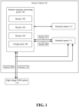
- FIG. 1 illustrates a block diagram of an isolation resistance monitoring system integrated with two high voltage systems, in accordance with one or more embodiments described herein.
- the block diagram comprises electric vehicle 101, isolation resistance monitoring system 102, resistors 103 -105, voltage meter 106, switches 107-110, smartcell system 111, high voltage EVSE system 112 and electrical chassis 113.
- electric vehicle 101 can comprise an isolation resistance monitoring system 102.
- Isolation resistance monitoring system 102 can be an electrical circuit comprising resistors 103, 104, and 105, and voltage meter 106.
- the isolation resistance monitoring system can monitor isolation resistance between the smartcell system 111 and the electrical chassis 113 of electric vehicle 101, and it can simultaneously monitor isolation resistance between the high voltage Electric Vehicle Supply Equipment (EVSE) system and the electrical chassis 113, wherein the EVSE system is an external DC charging station for electric vehicle 101.
- Isolation resistance monitoring system 102 can be electrically integrated with the smartcell system 111 via switches 107 and 108, wherein switches 107 and 108 can be respectively connected to each of the high voltage terminals of a high voltage bus of the smartcell system 111.
- isolation resistance monitoring system 102 can be electrically integrated with the high voltage EVSE system 112 via switches 109 and 110.
- Switches 109 and 110 can further provide a connection between the isolation resistance monitoring system 102 and the electrical circuit of the smartcell system 111, and they can allow the isolation resistance monitoring system to simultaneously monitor isolation resistance for the smartcell system and the high voltage EVSE system, during DC charging of electric vehicle 101.
- Isolation resistance monitoring system 102 can be integrated with the electrical chassis 113 of the electric vehicle 101, wherein the electrical chassis can be a reference point for the isolation resistance monitoring system 102.
- Voltage meter 106 can measure voltage through the smartcell system 111 and through the high voltage EVSE system 112 to assist the isolation resistance monitoring system 102 to monitor isolation resistance. Switches 107, 108, 109 and 110 can further assist the isolation resistance monitoring system 102 with measuring isolation resistance for electric vehicle 101. Isolation resistance monitoring system 102 can be controlled by a software and it can be used to locate isolation fault in different areas of the smartcell system 111, including isolation faults in cable harnesses, busbars, fuses, and other high voltage components of the smartcell system 111.
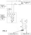
- FIG. 2 illustrates the architecture of the isolation resistance monitoring system, in accordance with one or more embodiments described herein.
- FIG. 2 comprises isolation resistance monitoring system 102, resistors 103-105, voltage meter 106, smartcell system 111, high voltage EVSE system 112, electrical chassis 113, and switches 107-110 of FIG. 1 , wherein resistors 103, 104 and 105 are respectively represented as R1, R2 and R3, and switches 107, 108, 109 and 110 are respectively represented as S1, S2, S3 and S4.
- resistor R3 can be connected in parallel with voltage meter 106.
- Resistors R1 and R2 can be connected in parallel with one another, and the parallel combination of resistor R3 and voltage meter 106 can be in series connection with the parallel combination of resistors R1 and R2.
- Switch S1 can be in series with resistor R1 and switch S2 can be in series with resistor R2 such that the isolation resistance monitoring system 102 can be galvanically connected with a high voltage bus of the smartcell system 111 via switches S1 and S2.
- the high voltage bus can be in parallel combination with one or more high voltage buses of smartcell system 111.
- switch S3 can be in series with resistor R1 and switch S4 can be in series with resistor R2 such that the isolation resistance monitoring system 102 can be galvanically connected with the smartcell system 111, and with high voltage EVSE system 112, wherein the high voltage EVSE system can be an external DC charging station, as discussed in one or more embodiments herein.
- switches S1, S2, S3 and S4 can be operated consecutively. Initially, all switches can be in the open position, switch S1 can be closed and the voltage through the circuit can be measured using the voltage meter 106, switch S1 can be opened, and the procedure can be repeated for switch S2 to measure isolation resistance for the parallel combination of high voltage buses of smartcell system. The procedure of consecutively opening and closing the plurality of switches can be repeated for switches S3 and S4 to measure isolation resistance for the smartcell system and for the high voltage EVSE system, wherein the smartcell system and the high voltage EVSE system are galvanically connected during DC charging.
- FIG. 3 illustrates the architecture of the isolation resistance monitoring system integrated with a smartcell system, in accordance with one or more embodiments described herein.
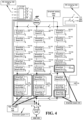
- FIG. 4 illustrates the architecture of the smartcell system, in accordance with one or more embodiments described herein.
- FIG. 3 and FIG. 4 comprise the smartcell system 111 and isolation resistance monitoring system 102 of FIG. 1 , contactors 301 - 314 of FIG. 3 , and smartcell battery pack 402, smartcell board 404, asynchronous motor (ASM) 406, high voltage bus 408, alternating current (AC) charging inlet 410, and DC charging inlet 411 of FIG. 4 .
- ASM synchronous motor
- AC alternating current
- the isolation resistance monitoring system 102 can be electrically integrated with the smartcell system 111 via switches S1 and S2 (also known as switches 107 and 108 per FIG. 1 and 2 ), as well as via switches S3 and S4 (also known as switches 109 and 110 per FIG. 3 and 4 ).
- the smartcell system topology comprises a smartcell battery pack 402 which can further comprise multiples of smartcell board 404.
- Each smartcell board 404 can control a battery module comprising one or more cells.
- a master node can control each smartcell board 404 and their respective battery modules such that the smartcell battery pack can produce different levels of AC output voltage at the pack level and it can produce different levels of DC output voltage at the pack or module level.
- a battery module can output up to 14 volts (V), and the one or more battery modules can be combined in series such that each series combination can be arranged to form three parallel strings of the battery modules.
- Each string can also comprise a combination of battery modules configured to form a high voltage bus 408 that can produce a galvanically isolated output of 400V.
- the 14 V battery modules on each string form the low voltage side of the smartcell system, which can be galvanically isolated from the high voltage buses on each string.
- the isolation resistance monitoring system 102 can be utilized for both AC and DC applications, for charging and non-charging use cases.
- the charging use cases can comprise DC charging of an electric vehicle via a high voltage EVSE system, during which the isolation resistance monitoring system can simultaneously monitor isolation resistance for the secondary circuit of the high voltage EVSE system and for the high voltage circuit of the smartcell system, including the high voltage buses and not including the low voltage, 14 V battery modules, by using switches S3 and S4.
- the isolated 400V bus if alive, can also be monitored by using S1 and S2.
- Contactors 301, 302, 305, 306, 307, and 308 can be closed for DC charging.
- the charging use cases can further comprise AC charging of the electric vehicle, during which isolation resistance can be monitored for the high voltage circuit of the smartcell system, including the high voltage buses and not including the low voltage, 14 V battery modules, by using switches S1 and S2.
- Contactors 301, 302, 311, 312, 313, and 314 can be closed for AC charging.
- the high voltage buses of the smartcell system can be energized to high voltage levels. Therefore, the solution can allow continuous isolation monitoring functionality for isolated high voltage buses with various voltage levels.
- the non-charging use cases can comprise isolation resistance measurement, as part of an isolation test, to detect isolation fault prior to AC and/or DC charging, during short-term and long-term parking, before every start-up, during every power-down, and before and after every service action of the electric vehicle.
- the high voltage buses of the smartcell system can be energized to safe voltage levels by the smartcell battery pack 402, wherein safe voltage levels can include voltage levels under 30 V for AC applications and voltage levels under 60 V for DC applications.
- the isolation resistance monitoring system 102 can detect isolation fault in the smartcell system 111, wherein the fault can be in cable harnesses, busbars, fuses, and other high voltage components of the smartcell system 111. Energizing the high voltage buses to non-hazardous voltage levels, for isolation resistance measurement for detecting isolation fault, can further allow service technicians to troubleshoot isolation faults much easier.
- the fault detection sequence which is described in greater detail in subsequent figures, can involve closing and opening several combinations of contactors 301 through 314 illustrated in the smartcell topology.
- the smartcell system 111 further comprises AC charging inlet 410 and DC charging inlet 411, and it is integrated with an asynchronous motor 406 (ASM 406).
- ASM is also known as the electric front axle drive (EFAD) since it drives the front axle of the electric vehicle.
- the isolation resistance monitoring system can employ the isolation fault detection sequence such that depending on where an isolation fault is detected in the smartcell system, it can prevent AC charging, DC charging or front wheel drive of the vehicle, by opening the respective contactors to the AC charging inlet, DC charging inlet and the ASM, and it can prevent energization of the high voltage buses.
- FIG. 5 illustrates an isolation resistance monitoring method that facilitates isolation resistance monitoring, in accordance with one or more embodiments described herein. Repetitive description of like elements and/or processes employed in respective embodiments is omitted for sake of brevity.
- environment 500 can comprise, at 502, an isolation resistance monitoring method which can facilitate monitoring, by an isolation resistance monitoring system, isolation resistance, simultaneously, for a smartcell system of an electric vehicle, and for a DC charging source external to the electric vehicle, wherein a voltage meter measures voltage to assist with the isolation resistance monitoring.
- FIG. 6 illustrates a flow diagram of an isolation resistance monitoring method that facilitates isolation resistance monitoring and isolation fault detection, in accordance with one or more embodiments described herein.
- environment 600 can comprise, at 502, an isolation resistance monitoring method which can facilitate monitoring, by an isolation resistance monitoring system, isolation resistance, simultaneously, for a smartcell system of an electric vehicle, and for a DC charging source external to the electric vehicle, wherein a voltage meter measures voltage to assist with the isolation resistance monitoring.
- the isolation resistance monitoring method can facilitate detecting, by an isolation resistance monitoring system, an isolation fault in the smartcell system, wherein one or more contactors of the smartcell system are configured to design an isolation test for detecting the isolation fault.
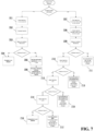
- FIG. 7 illustrates a flow diagram of an isolation resistance monitoring method that facilitates isolation fault detection, in accordance with one or more embodiments described herein. Repetitive description of like elements and/or processes employed in respective embodiments is omitted for sake of brevity.
- FIG. 7 is to be understood in conjunction with FIG. 3 and 4 where the smartcell system architecture is addressed.
- one or more contactors of a smartcell system can be configured to design an isolation test for detecting isolation fault, using the isolation resistance monitoring system, due to one or more components in the smartcell system.
- the isolation test can comprise two isolation test sequences, respectively, for a first and a second use case.
- the first use case comprises isolation fault detection in the smartcell system prior to AC charging and/or DC charging.
- the second use case comprises isolation fault detection in the smartcell system during short-term and long-term parking, before every start-up, during every power-down, and before and after every service action of an electric vehicle.
- the first isolation test sequence is described by steps 701 -706 which address the first use case comprising isolation fault detection in the smartcell system prior to AC charging and/or DC charging.
- all contactors can be in the open position.
- contactors 301, 302, 305, 306, 309, and 310 (as illustrated in FIG. 3 ) can be closed, and the system can be energized by the smartcell battery pack 402 to low DC voltage levels at 702, followed by isolation resistance measurement of the smartcell system 111 at 703. If an isolation failure is detected in the system, charging can be prevented at 704.
- the test can be concluded by opening contactors 301, 302, 305, 306, 309, and 310, at 705, and the smartcell battery pack can be allowed to be charged either via an AC charging source or a DC charging source, at 706. Further isolation resistance monitoring of the smartcell system can operate upon a request.
- the second isolation test sequence is described by steps 707-717 which address the second use case comprising isolation fault detection in the smartcell system 111 during short-term and long-term parking, before every start-up, during every power-down, and before and after every service action of an electric vehicle.
- all contactors can be in the open position.
- contactors 301, 302, 305, 306, 307, 308, 309, 310, 311, 312, 313, and 314 (as illustrated in FIG. 3 ) can be closed, and the system can be energized by the smartcell battery pack 402 to low DC voltage levels at 708.
- the isolation resistance of the smartcell system 111 can be measured by the isolation resistance monitoring system102. If no isolation faults can be detected, high voltage energization of the smartcell system 111 can be allowed at 711, and if an isolation fault can be detected, contactors 311, 312, 313 and 314 can be disconnected at 710.
- step 710 If no isolation fault can be detected after step 710, it can imply that the fault exists within the onboard section of the AC charging bus, since contactors 311, 312, 313, and 314 can provide a connection between the smartcell system 111 and the AC charging inlet 410. Thus, AC charging can be prevented, and high voltage energization of the smartcell system can be allowed at 713. If an isolation fault can be detected after step 710, contactors 307 and 308 can be opened at 712.
- step 712 If no isolation fault can be detected after step 712, it can imply that the fault exists within the onboard section of the DC charging bus, since contactors 307 and 308 can provide a connection between the smartcell system 111 and the DC charging inlet 411. Thus, DC charging can be prevented, and high voltage energization of the smartcell system can be allowed at 715. If an isolation fault can be detected after step 712, contactors 309 and 310 can be opened at 714.
- step 714 If no isolation fault can be detected after step 714, it can imply that the fault exists with ASM 406, since contactors 309 and 310 can provide a connection between the smartcell system 111 and ASM 406. Thus, front wheel drive can be prevented, and high voltage energization of the smartcell system can be allowed at 717. If an isolation fault can be detected after step 714, high voltage energization can be prevented at 716, and the test can be concluded.
- an isolation fault detection test can be performed upon a request, and the isolation test sequence can be executed at safe voltage levels by energizing the high voltage buses of the smartcell system accordingly.
- the isolation fault detection test can detect isolation faults in the smartcell system, where in the faults can be caused in cable harness, busbars, fuses and other high voltage components of the smartcell system.
Landscapes
- Physics & Mathematics (AREA)
- General Physics & Mathematics (AREA)
- Engineering & Computer Science (AREA)
- Chemical & Material Sciences (AREA)
- Combustion & Propulsion (AREA)
- Power Engineering (AREA)
- Transportation (AREA)
- Mechanical Engineering (AREA)
- Electric Propulsion And Braking For Vehicles (AREA)
- Testing Of Short-Circuits, Discontinuities, Leakage, Or Incorrect Line Connections (AREA)
- Secondary Cells (AREA)
Claims (15)
- System zur Überwachung eines Isolationswiderstands (102), umfassend:einen elektrischen Schaltkreis, umfassend:ein oder mehrere Widerstände (103, 104, 105); undeinen Spannungsmesser (106), der die Spannung misst, sodass die Spannungsmessung die Überwachung des Isolationswiderstands gleichzeitig zwischen einem Batteriesystem (111) eines Elektrofahrzeugs (101) und einem elektrischen Chassis (113) des Elektrofahrzeugs (101) sowie zwischen einer externen Gleichstrom- (DC) Ladequelle und dem elektrischen Chassis (113) unterstützt, wobei die DC-Ladequelle ein Hochspannungs-Elektrofahrzeug-Ladesystem (EVSE) (112) umfasst, welches eine externe Ladestation für das Elektrofahrzeug (101) darstellt,das System zur Überwachung eines Isolationswiderstands (102) weiter umfassend:eine erste Anzahl von Schaltern (107, 108), die das System zur Überwachung eines Isolationswiderstands (102) elektrisch mit dem Batteriesystem (111) des Elektrofahrzeugs (101) integrieren; undeine zweite Anzahl von Schaltern (109, 110), die das System zur Überwachung eines Isolationswiderstands (102) elektrisch mit dem Hochspannungs-EVSE-System (112) integrieren.
- Das System nach Anspruch 1, wobei das System zur Überwachung eines Isolationswiderstands (102) den Isolationswiderstand gleichzeitig für das Hochspannungs-EVSE-System (112) und für ein oder mehrere Hochspannungsbusse des Batteriesystems (111) während des DC-Ladens überwacht.
- Das System nach Anspruch 2, wobei die ein oder mehreren Hochspannungsbusse des Batteriesystems (111) für den DC-Ladeanwendungsfall auf hohe Spannungspegel eingestellt sind.
- Das System nach Anspruch 2, wobei die ein oder mehreren Hochspannungsbusse während Nicht-Ladeanwendungsfällen des Systems zur Überwachung eines Isolationswiderstands (102) auf niedrige Spannungspegel eingestellt sind.
- Das System nach Anspruch 4, wobei die Nicht-Ladeanwendungsfälle die Messung des Isolationswiderstands als Teil eines Isolationstests zur Erkennung von Isolationsfehlern im Batteriesystem (111) vor dem AC- und/oder DC-Laden, während kurz- und langfristigem Parken, vor jedem Startvorgang, während jeder Abschaltung und vor sowie nach jeder Wartungsmaßnahme des Elektrofahrzeugs (101) für AC- und/oder DC-Anwendungen umfassen.
- Das System nach Anspruch 4, wobei Niederspannungspegel Spannungspegel unter 30 V für AC-Anwendungen und Spannungspegel unter 60 V für DC-Anwendungen umfassen.
- Verfahren zur Überwachung eines Isolationswiderstands, umfassend:überwachen, durch ein System zur Überwachung eines Isolationswiderstands (102), des Isolationswiderstands gleichzeitig zwischen einem Batteriesystem (111) eines Elektrofahrzeugs (101) und einem elektrischen Chassis (113) des Elektrofahrzeugs (101) sowie zwischen einer externen DC-Ladequelle und dem elektrischen Chassis (113), wobei ein Spannungsmesser (106) die Spannung misst, um die Überwachung des Isolationswiderstands zu unterstützen, wobei die DC-Ladequelle ein Hochspannungs-Elektrofahrzeug-Ladesystem (EVSE) (112) umfasst, welches eine externe Ladestation für das Elektrofahrzeug (101) darstellt,integrieren, durch das System, des Überwachungssystems mit dem Batteriesystem (111) des Elektrofahrzeugs (101) unter Verwendung einer ersten Anzahl von Schaltern (107, 108);integrieren, durch das System, des Systems zur Überwachung eines Isolationswiderstands (102) mit dem Hochspannungs-EVSE-System (112) des Elektrofahrzeugs (101) unter Verwendung einer zweiten Anzahl von Schaltern (109, 110); undüberwachen, durch das System, des Systems zur Überwachung eines Isolationswiderstands (102) gleichzeitig für das Hochspannungs-EVSE-System (112) und für ein oder mehrere Hochspannungsbusse des Batteriesystems (111) während des DC-Ladens.
- Das Verfahren nach Anspruch 7, wobei die ein oder mehreren Hochspannungsbusse des Batteriesystems (111) für den DC-Ladeanwendungsfall auf hohe Spannungspegel eingestellt sind; und wobei die ein oder mehreren Hochspannungsbusse während Nicht-Ladeanwendungsfällen des Systems zur Überwachung eines Isolationswiderstands auf niedrige Spannungspegel eingestellt sind.
- Das Verfahren nach Anspruch 8, wobei die Nicht-Ladeanwendungsfälle die Messung des Isolationswiderstands als Teil eines Isolationstests zur Erkennung von Isolationsfehlern im Batteriesystem (111) vor dem AC- und/oder DC-Laden, während kurz- und langfristigem Parken, vor jedem Startvorgang, während jeder Abschaltung und vor sowie nach jeder Wartungsmaßnahme des Elektrofahrzeugs (101) für AC- und/oder DC-Anwendungen umfassen.
- Ein Verfahren zur Erkennung von Isolationsfehlern, umfassend:
erkennen, durch ein System zur Überwachung eines Isolationswiderstands (102) gemäß einem der Ansprüche 1 bis 6, eines Isolationsfehlers in einem Batteriesystem (111), wobei ein oder mehrere Schaltgeräte des Batteriesystems (111) an einem Isolationstest zur Erkennung des Isolationsfehlers teilnehmen. - Das Verfahren nach Anspruch 10, umfassend:ausführen, durch das System, einer ersten Isolationstestsequenz des Isolationstests für einen ersten Anwendungsfall;ausführen, durch das System, der ersten Isolationstestsequenz, sodass der Isolationsfehler durch Einstellen des Batteriesystems (111) auf niedrige Spannungspegel lokalisiert wird;erkennen, durch das System, des Isolationsfehlers für den ersten Anwendungsfall, wobei der erste Anwendungsfall die Erkennung von Isolationsfehlern im Batteriesystem (111) vor dem AC- und/oder DC-Laden umfasst;ausführen, durch das System, einer zweiten Isolationstestsequenz des Isolationstests für einen zweiten Anwendungsfall;ausführen, durch das System, der zweiten Isolationstestsequenz, sodass der Isolationsfehler durch Einstellen des Batteriesystems (111) auf niedrige Spannungspegel lokalisiert wird; underkennen, durch das System, des Isolationsfehlers für den zweiten Anwendungsfall, wobei der zweite Anwendungsfall die Erkennung von Isolationsfehlern im Batteriesystem (111) während kurz- und langfristigem Parken, vor jedem Startvorgang, während jeder Abschaltung und vor sowie nach jeder Wartungsmaßnahme eines Elektrofahrzeugs (101) umfasst.
- Das Verfahren nach Anspruch 11, wobei im ersten Isolationstestsequenz das Laden verhindert wird, wenn ein Isolationsfehler im Batteriesystem (111) erkannt wird.
- Das Verfahren nach Anspruch 11, wobei in der zweiten Isolationstestsequenz das AC-Laden verhindert werden kann, wenn ein Isolationsfehler in einem Bordabschnitt eines AC-Ladebusses erkannt wird.
- Das Verfahren nach Anspruch 11, wobei in der zweiten Isolationstestsequenz das DC-Laden verhindert werden kann, wenn ein Isolationsfehler in einem Bordabschnitt eines DC-Ladebusses erkannt wird.
- Das Verfahren nach Anspruch 10, umfassend:
erkennen, durch das System, des Isolationsfehlers im Batteriesystem (111), wobei das Verfahren zur Erkennung von Isolationsfehlern Servicetechnikern dabei hilft, Isolationsfehler zu beheben, und die Fahrbarkeit eines Elektrofahrzeugs (101) unterstützt.
Applications Claiming Priority (1)
| Application Number | Priority Date | Filing Date | Title |
|---|---|---|---|
| US17/653,666 US12123904B2 (en) | 2022-03-07 | 2022-03-07 | Isolation resistance monitoring for high voltage systems |
Publications (2)
| Publication Number | Publication Date |
|---|---|
| EP4242672A1 EP4242672A1 (de) | 2023-09-13 |
| EP4242672B1 true EP4242672B1 (de) | 2025-05-28 |
Family
ID=85510824
Family Applications (1)
| Application Number | Title | Priority Date | Filing Date |
|---|---|---|---|
| EP23160557.7A Active EP4242672B1 (de) | 2022-03-07 | 2023-03-07 | Isolationswiderstandsüberwachung für hochspannungssysteme |
Country Status (3)
| Country | Link |
|---|---|
| US (1) | US12123904B2 (de) |
| EP (1) | EP4242672B1 (de) |
| CN (1) | CN116718835A (de) |
Families Citing this family (1)
| Publication number | Priority date | Publication date | Assignee | Title |
|---|---|---|---|---|
| JP7652101B2 (ja) * | 2022-02-08 | 2025-03-27 | トヨタ自動車株式会社 | 充放電装置、車両、および、充放電装置の制御方法 |
Family Cites Families (18)
| Publication number | Priority date | Publication date | Assignee | Title |
|---|---|---|---|---|
| JP4326415B2 (ja) | 2004-07-06 | 2009-09-09 | 三洋電機株式会社 | 車両用の電源装置 |
| US9046559B2 (en) | 2012-05-09 | 2015-06-02 | Curtis Instruments, Inc. | Isolation monitor |
| US9696384B2 (en) * | 2012-08-24 | 2017-07-04 | GM Global Technology Operations LLC | High voltage bus-to-chassis isolation resistance and Y-capacitance measurement |
| US9063179B2 (en) * | 2012-09-26 | 2015-06-23 | Lg Chem, Ltd. | System and method for determining an isolation resistance of a battery pack disposed on a vehicle chassis |
| GB2517184B (en) * | 2013-08-14 | 2016-01-20 | Jaguar Land Rover Ltd | Method and system for controlling an isolated HV circuit |
| KR101512395B1 (ko) | 2013-10-08 | 2015-04-16 | 현대오트론 주식회사 | 절연저항 측정 장치 및 방법 |
| US9720049B2 (en) | 2014-07-22 | 2017-08-01 | Robert Bosch Battery Systems Llc | System and method for high voltage system isolation resistance measurement |
| CN105109361B (zh) | 2015-07-01 | 2018-02-02 | 深圳电擎科技有限公司 | 电动汽车多功能电动力综合系统及综合控制系统 |
| JP6772720B2 (ja) | 2016-09-23 | 2020-10-21 | 三菱自動車工業株式会社 | 漏電検出装置 |
| EP3361271B1 (de) | 2017-02-08 | 2022-06-01 | Fico Triad, S.A. | Vorrichtung und verfahren zur messung des isolationswiderstands eines batteriebetriebenen systems |
| EP3608152B1 (de) | 2018-08-06 | 2022-06-22 | Ningbo Geely Automobile Research & Development Co. Ltd. | Verfahren zur detektion eines isolierungsfehlers |
| US11353563B2 (en) * | 2018-09-13 | 2022-06-07 | Pixart Imaging Inc. | Avalanche diode based object detection device |
| US11254215B2 (en) | 2018-11-21 | 2022-02-22 | Volvo Car Corporation | Isolation resistance measurement of power system in vehicle |
| JP6986004B2 (ja) | 2018-12-03 | 2021-12-22 | 株式会社デンソー | 絶縁抵抗検出装置 |
| US11754629B2 (en) * | 2019-08-06 | 2023-09-12 | GM Global Technology Operations LLC | Active isolation detection using adaptive bias resistance |
| CN114076878B (zh) | 2020-08-14 | 2024-09-06 | 北京新能源汽车股份有限公司 | 一种绝缘检测方法、装置、控制设备及汽车 |
| CN113715663B (zh) | 2021-08-12 | 2023-02-10 | 深圳欣锐科技股份有限公司 | 绝缘检测电路、电动汽车和充电桩 |
| US20240109448A1 (en) * | 2022-09-29 | 2024-04-04 | Rivian Ip Holdings, Llc | Monitoring isolation resistance to validate vehicle charger functionality |
-
2022
- 2022-03-07 US US17/653,666 patent/US12123904B2/en active Active
-
2023
- 2023-03-07 EP EP23160557.7A patent/EP4242672B1/de active Active
- 2023-03-07 CN CN202310234165.4A patent/CN116718835A/zh active Pending
Also Published As
| Publication number | Publication date |
|---|---|
| US12123904B2 (en) | 2024-10-22 |
| EP4242672A1 (de) | 2023-09-13 |
| CN116718835A (zh) | 2023-09-08 |
| US20230280384A1 (en) | 2023-09-07 |
Similar Documents
| Publication | Publication Date | Title |
|---|---|---|
| US11091039B2 (en) | Bus leakage resistance estimation for electrical isolation testing and diagnostics | |
| US10114058B2 (en) | System and method for high voltage leakage detection | |
| US8688317B2 (en) | Method for diagnosing the operation of a device for cutting off and connecting a battery from/to the onboard power network of a motor vehicle | |
| US10962597B2 (en) | Measurement apparatus, energy storage apparatus, measurement system, and offset error measurement method | |
| US9194918B2 (en) | Leakage detection circuit with integral circuit robustness check | |
| CN105938171B (zh) | 使用dc总线泄漏硬件的ac牵引马达故障检测 | |
| US7109604B2 (en) | Device for distributing electrical energy and method for monitoring the distribution of energy | |
| US10882403B2 (en) | Vehicle high/low voltage systems isolation testing | |
| US11091038B2 (en) | Technique for insulation monitoring in vehicles | |
| EP3361271B1 (de) | Vorrichtung und verfahren zur messung des isolationswiderstands eines batteriebetriebenen systems | |
| KR101708984B1 (ko) | 전기 고전압 시스템에서 전압의 부재를 결정하기 위한 방법 및 전기 고전압 시스템 | |
| CN105572540A (zh) | 自适应的电动汽车高压电安全故障诊断预警定位监测系统 | |
| KR20120059943A (ko) | 배터리 전압 측정 라인의 단선 검출용 전압 측정 장치 | |
| CN207481815U (zh) | 电动汽车高压上下电系统 | |
| US20250076353A1 (en) | System and method for isolation resistance measurement | |
| EP4242672A1 (de) | Isolationswiderstandsüberwachung für hochspannungssysteme | |
| US11858360B2 (en) | Method for operating at least one electrical component of a vehicle | |
| US20130270901A1 (en) | Method and Arrangement for Diagnosing Drivers of Contactors, Battery, and Motor Vehicle having such a Battery | |
| CN108508272B (zh) | 用于车辆中的绝缘监测的技术 | |
| WO2022136434A2 (en) | Method and equipment for monitoring a failure in a high-voltage circuit of a vehicle, and high-voltage circuit system | |
| KR20220135327A (ko) | 전기 자동차의 전력 분배 유닛 고장진단장치 | |
| CN118671579A (zh) | 一种继电器状态检测电路及检测方法、电池管理系统 | |
| CN117728057A (zh) | 电池系统、用于诊断电池系统的方法 | |
| KR102839450B1 (ko) | 배터리 장치 및 드리프트 오류 진단 방법 | |
| US20250070588A1 (en) | Partial pre-charge of the high voltage system |
Legal Events
| Date | Code | Title | Description |
|---|---|---|---|
| PUAI | Public reference made under article 153(3) epc to a published international application that has entered the european phase |
Free format text: ORIGINAL CODE: 0009012 |
|
| STAA | Information on the status of an ep patent application or granted ep patent |
Free format text: STATUS: THE APPLICATION HAS BEEN PUBLISHED |
|
| AK | Designated contracting states |
Kind code of ref document: A1 Designated state(s): AL AT BE BG CH CY CZ DE DK EE ES FI FR GB GR HR HU IE IS IT LI LT LU LV MC ME MK MT NL NO PL PT RO RS SE SI SK SM TR |
|
| STAA | Information on the status of an ep patent application or granted ep patent |
Free format text: STATUS: REQUEST FOR EXAMINATION WAS MADE |
|
| 17P | Request for examination filed |
Effective date: 20240308 |
|
| RBV | Designated contracting states (corrected) |
Designated state(s): AL AT BE BG CH CY CZ DE DK EE ES FI FR GB GR HR HU IE IS IT LI LT LU LV MC ME MK MT NL NO PL PT RO RS SE SI SK SM TR |
|
| GRAP | Despatch of communication of intention to grant a patent |
Free format text: ORIGINAL CODE: EPIDOSNIGR1 |
|
| STAA | Information on the status of an ep patent application or granted ep patent |
Free format text: STATUS: GRANT OF PATENT IS INTENDED |
|
| INTG | Intention to grant announced |
Effective date: 20241008 |
|
| GRAJ | Information related to disapproval of communication of intention to grant by the applicant or resumption of examination proceedings by the epo deleted |
Free format text: ORIGINAL CODE: EPIDOSDIGR1 |
|
| STAA | Information on the status of an ep patent application or granted ep patent |
Free format text: STATUS: REQUEST FOR EXAMINATION WAS MADE |
|
| GRAP | Despatch of communication of intention to grant a patent |
Free format text: ORIGINAL CODE: EPIDOSNIGR1 |
|
| STAA | Information on the status of an ep patent application or granted ep patent |
Free format text: STATUS: GRANT OF PATENT IS INTENDED |
|
| INTC | Intention to grant announced (deleted) | ||
| INTG | Intention to grant announced |
Effective date: 20250210 |
|
| GRAS | Grant fee paid |
Free format text: ORIGINAL CODE: EPIDOSNIGR3 |
|
| GRAA | (expected) grant |
Free format text: ORIGINAL CODE: 0009210 |
|
| STAA | Information on the status of an ep patent application or granted ep patent |
Free format text: STATUS: THE PATENT HAS BEEN GRANTED |
|
| AK | Designated contracting states |
Kind code of ref document: B1 Designated state(s): AL AT BE BG CH CY CZ DE DK EE ES FI FR GB GR HR HU IE IS IT LI LT LU LV MC ME MK MT NL NO PL PT RO RS SE SI SK SM TR |
|
| REG | Reference to a national code |
Ref country code: GB Ref legal event code: FG4D |
|
| REG | Reference to a national code |
Ref country code: CH Ref legal event code: EP |
|
| REG | Reference to a national code |
Ref country code: IE Ref legal event code: FG4D Ref country code: DE Ref legal event code: R096 Ref document number: 602023003655 Country of ref document: DE |
|
| P01 | Opt-out of the competence of the unified patent court (upc) registered |
Free format text: CASE NUMBER: APP_25238/2025 Effective date: 20250527 |
|
| REG | Reference to a national code |
Ref country code: NL Ref legal event code: MP Effective date: 20250528 |
|
| PG25 | Lapsed in a contracting state [announced via postgrant information from national office to epo] |
Ref country code: FI Free format text: LAPSE BECAUSE OF FAILURE TO SUBMIT A TRANSLATION OF THE DESCRIPTION OR TO PAY THE FEE WITHIN THE PRESCRIBED TIME-LIMIT Effective date: 20250528 Ref country code: ES Free format text: LAPSE BECAUSE OF FAILURE TO SUBMIT A TRANSLATION OF THE DESCRIPTION OR TO PAY THE FEE WITHIN THE PRESCRIBED TIME-LIMIT Effective date: 20250528 |
|
| REG | Reference to a national code |
Ref country code: LT Ref legal event code: MG9D |
|
| PG25 | Lapsed in a contracting state [announced via postgrant information from national office to epo] |
Ref country code: GR Free format text: LAPSE BECAUSE OF FAILURE TO SUBMIT A TRANSLATION OF THE DESCRIPTION OR TO PAY THE FEE WITHIN THE PRESCRIBED TIME-LIMIT Effective date: 20250829 Ref country code: NO Free format text: LAPSE BECAUSE OF FAILURE TO SUBMIT A TRANSLATION OF THE DESCRIPTION OR TO PAY THE FEE WITHIN THE PRESCRIBED TIME-LIMIT Effective date: 20250828 |
|
| PG25 | Lapsed in a contracting state [announced via postgrant information from national office to epo] |
Ref country code: NL Free format text: LAPSE BECAUSE OF FAILURE TO SUBMIT A TRANSLATION OF THE DESCRIPTION OR TO PAY THE FEE WITHIN THE PRESCRIBED TIME-LIMIT Effective date: 20250528 Ref country code: PL Free format text: LAPSE BECAUSE OF FAILURE TO SUBMIT A TRANSLATION OF THE DESCRIPTION OR TO PAY THE FEE WITHIN THE PRESCRIBED TIME-LIMIT Effective date: 20250528 |
|
| PG25 | Lapsed in a contracting state [announced via postgrant information from national office to epo] |
Ref country code: BG Free format text: LAPSE BECAUSE OF FAILURE TO SUBMIT A TRANSLATION OF THE DESCRIPTION OR TO PAY THE FEE WITHIN THE PRESCRIBED TIME-LIMIT Effective date: 20250528 |
|
| PG25 | Lapsed in a contracting state [announced via postgrant information from national office to epo] |
Ref country code: HR Free format text: LAPSE BECAUSE OF FAILURE TO SUBMIT A TRANSLATION OF THE DESCRIPTION OR TO PAY THE FEE WITHIN THE PRESCRIBED TIME-LIMIT Effective date: 20250528 |
|
| PG25 | Lapsed in a contracting state [announced via postgrant information from national office to epo] |
Ref country code: RS Free format text: LAPSE BECAUSE OF FAILURE TO SUBMIT A TRANSLATION OF THE DESCRIPTION OR TO PAY THE FEE WITHIN THE PRESCRIBED TIME-LIMIT Effective date: 20250828 |
|
| PG25 | Lapsed in a contracting state [announced via postgrant information from national office to epo] |
Ref country code: IS Free format text: LAPSE BECAUSE OF FAILURE TO SUBMIT A TRANSLATION OF THE DESCRIPTION OR TO PAY THE FEE WITHIN THE PRESCRIBED TIME-LIMIT Effective date: 20250928 |
|
| PG25 | Lapsed in a contracting state [announced via postgrant information from national office to epo] |
Ref country code: LV Free format text: LAPSE BECAUSE OF FAILURE TO SUBMIT A TRANSLATION OF THE DESCRIPTION OR TO PAY THE FEE WITHIN THE PRESCRIBED TIME-LIMIT Effective date: 20250528 |
|
| REG | Reference to a national code |
Ref country code: AT Ref legal event code: MK05 Ref document number: 1798871 Country of ref document: AT Kind code of ref document: T Effective date: 20250528 |
|
| PG25 | Lapsed in a contracting state [announced via postgrant information from national office to epo] |
Ref country code: DK Free format text: LAPSE BECAUSE OF FAILURE TO SUBMIT A TRANSLATION OF THE DESCRIPTION OR TO PAY THE FEE WITHIN THE PRESCRIBED TIME-LIMIT Effective date: 20250528 Ref country code: SM Free format text: LAPSE BECAUSE OF FAILURE TO SUBMIT A TRANSLATION OF THE DESCRIPTION OR TO PAY THE FEE WITHIN THE PRESCRIBED TIME-LIMIT Effective date: 20250528 Ref country code: AT Free format text: LAPSE BECAUSE OF FAILURE TO SUBMIT A TRANSLATION OF THE DESCRIPTION OR TO PAY THE FEE WITHIN THE PRESCRIBED TIME-LIMIT Effective date: 20250528 |
|
| PG25 | Lapsed in a contracting state [announced via postgrant information from national office to epo] |
Ref country code: CZ Free format text: LAPSE BECAUSE OF FAILURE TO SUBMIT A TRANSLATION OF THE DESCRIPTION OR TO PAY THE FEE WITHIN THE PRESCRIBED TIME-LIMIT Effective date: 20250528 |
|
| PG25 | Lapsed in a contracting state [announced via postgrant information from national office to epo] |
Ref country code: EE Free format text: LAPSE BECAUSE OF FAILURE TO SUBMIT A TRANSLATION OF THE DESCRIPTION OR TO PAY THE FEE WITHIN THE PRESCRIBED TIME-LIMIT Effective date: 20250528 |
|
| PG25 | Lapsed in a contracting state [announced via postgrant information from national office to epo] |
Ref country code: SK Free format text: LAPSE BECAUSE OF FAILURE TO SUBMIT A TRANSLATION OF THE DESCRIPTION OR TO PAY THE FEE WITHIN THE PRESCRIBED TIME-LIMIT Effective date: 20250528 |
|
| PG25 | Lapsed in a contracting state [announced via postgrant information from national office to epo] |
Ref country code: IT Free format text: LAPSE BECAUSE OF FAILURE TO SUBMIT A TRANSLATION OF THE DESCRIPTION OR TO PAY THE FEE WITHIN THE PRESCRIBED TIME-LIMIT Effective date: 20250528 |
|
| REG | Reference to a national code |
Ref country code: DE Ref legal event code: R097 Ref document number: 602023003655 Country of ref document: DE |
|
| PLBE | No opposition filed within time limit |
Free format text: ORIGINAL CODE: 0009261 |
|
| STAA | Information on the status of an ep patent application or granted ep patent |
Free format text: STATUS: NO OPPOSITION FILED WITHIN TIME LIMIT |
|
| REG | Reference to a national code |
Ref country code: CH Ref legal event code: L10 Free format text: ST27 STATUS EVENT CODE: U-0-0-L10-L00 (AS PROVIDED BY THE NATIONAL OFFICE) Effective date: 20260409 |
|
| PGFP | Annual fee paid to national office [announced via postgrant information from national office to epo] |
Ref country code: DE Payment date: 20260219 Year of fee payment: 4 |
|
| PGFP | Annual fee paid to national office [announced via postgrant information from national office to epo] |
Ref country code: FR Payment date: 20260219 Year of fee payment: 4 |
|
| 26N | No opposition filed |
Effective date: 20260303 |