EP4242003A1 - Auftragseinheit - Google Patents
Auftragseinheit Download PDFInfo
- Publication number
- EP4242003A1 EP4242003A1 EP23150247.7A EP23150247A EP4242003A1 EP 4242003 A1 EP4242003 A1 EP 4242003A1 EP 23150247 A EP23150247 A EP 23150247A EP 4242003 A1 EP4242003 A1 EP 4242003A1
- Authority
- EP
- European Patent Office
- Prior art keywords
- recording sheet
- applying unit
- sensor
- printer
- adhesive
- Prior art date
- Legal status (The legal status is an assumption and is not a legal conclusion. Google has not performed a legal analysis and makes no representation as to the accuracy of the status listed.)
- Pending
Links
Images






Classifications
-
- B—PERFORMING OPERATIONS; TRANSPORTING
- B41—PRINTING; LINING MACHINES; TYPEWRITERS; STAMPS
- B41J—TYPEWRITERS; SELECTIVE PRINTING MECHANISMS, i.e. MECHANISMS PRINTING OTHERWISE THAN FROM A FORME; CORRECTION OF TYPOGRAPHICAL ERRORS
- B41J3/00—Typewriters or selective printing or marking mechanisms characterised by the purpose for which they are constructed
- B41J3/407—Typewriters or selective printing or marking mechanisms characterised by the purpose for which they are constructed for marking on special material
- B41J3/4075—Tape printers; Label printers
-
- B—PERFORMING OPERATIONS; TRANSPORTING
- B41—PRINTING; LINING MACHINES; TYPEWRITERS; STAMPS
- B41J—TYPEWRITERS; SELECTIVE PRINTING MECHANISMS, i.e. MECHANISMS PRINTING OTHERWISE THAN FROM A FORME; CORRECTION OF TYPOGRAPHICAL ERRORS
- B41J3/00—Typewriters or selective printing or marking mechanisms characterised by the purpose for which they are constructed
- B41J3/44—Typewriters or selective printing mechanisms having dual functions or combined with, or coupled to, apparatus performing other functions
-
- B—PERFORMING OPERATIONS; TRANSPORTING
- B05—SPRAYING OR ATOMISING IN GENERAL; APPLYING FLUENT MATERIALS TO SURFACES, IN GENERAL
- B05C—APPARATUS FOR APPLYING FLUENT MATERIALS TO SURFACES, IN GENERAL
- B05C1/00—Apparatus in which liquid or other fluent material is applied to the surface of the work by contact with a member carrying the liquid or other fluent material, e.g. a porous member loaded with a liquid to be applied as a coating
- B05C1/02—Apparatus in which liquid or other fluent material is applied to the surface of the work by contact with a member carrying the liquid or other fluent material, e.g. a porous member loaded with a liquid to be applied as a coating for applying liquid or other fluent material to separate articles
- B05C1/025—Apparatus in which liquid or other fluent material is applied to the surface of the work by contact with a member carrying the liquid or other fluent material, e.g. a porous member loaded with a liquid to be applied as a coating for applying liquid or other fluent material to separate articles to flat rectangular articles, e.g. flat sheets
-
- B—PERFORMING OPERATIONS; TRANSPORTING
- B05—SPRAYING OR ATOMISING IN GENERAL; APPLYING FLUENT MATERIALS TO SURFACES, IN GENERAL
- B05C—APPARATUS FOR APPLYING FLUENT MATERIALS TO SURFACES, IN GENERAL
- B05C1/00—Apparatus in which liquid or other fluent material is applied to the surface of the work by contact with a member carrying the liquid or other fluent material, e.g. a porous member loaded with a liquid to be applied as a coating
- B05C1/04—Apparatus in which liquid or other fluent material is applied to the surface of the work by contact with a member carrying the liquid or other fluent material, e.g. a porous member loaded with a liquid to be applied as a coating for applying liquid or other fluent material to work of indefinite length
- B05C1/08—Apparatus in which liquid or other fluent material is applied to the surface of the work by contact with a member carrying the liquid or other fluent material, e.g. a porous member loaded with a liquid to be applied as a coating for applying liquid or other fluent material to work of indefinite length using a roller or other rotating member which contacts the work along a generating line
- B05C1/0826—Apparatus in which liquid or other fluent material is applied to the surface of the work by contact with a member carrying the liquid or other fluent material, e.g. a porous member loaded with a liquid to be applied as a coating for applying liquid or other fluent material to work of indefinite length using a roller or other rotating member which contacts the work along a generating line the work being a web or sheets
-
- B—PERFORMING OPERATIONS; TRANSPORTING
- B05—SPRAYING OR ATOMISING IN GENERAL; APPLYING FLUENT MATERIALS TO SURFACES, IN GENERAL
- B05C—APPARATUS FOR APPLYING FLUENT MATERIALS TO SURFACES, IN GENERAL
- B05C11/00—Component parts, details or accessories not specifically provided for in groups B05C1/00 - B05C9/00
- B05C11/10—Storage, supply or control of liquid or other fluent material; Recovery of excess liquid or other fluent material
- B05C11/1002—Means for controlling supply, i.e. flow or pressure, of liquid or other fluent material to the applying apparatus, e.g. valves
- B05C11/1015—Means for controlling supply, i.e. flow or pressure, of liquid or other fluent material to the applying apparatus, e.g. valves responsive to a conditions of ambient medium or target, e.g. humidity, temperature ; responsive to position or movement of the coating head relative to the target
-
- B—PERFORMING OPERATIONS; TRANSPORTING
- B41—PRINTING; LINING MACHINES; TYPEWRITERS; STAMPS
- B41J—TYPEWRITERS; SELECTIVE PRINTING MECHANISMS, i.e. MECHANISMS PRINTING OTHERWISE THAN FROM A FORME; CORRECTION OF TYPOGRAPHICAL ERRORS
- B41J11/00—Devices or arrangements of selective printing mechanisms, e.g. ink-jet printers or thermal printers, for supporting or handling copy material in sheet or web form
- B41J11/0015—Devices or arrangements of selective printing mechanisms, e.g. ink-jet printers or thermal printers, for supporting or handling copy material in sheet or web form for treating before, during or after printing or for uniform coating or laminating the copy material before or after printing
-
- B—PERFORMING OPERATIONS; TRANSPORTING
- B41—PRINTING; LINING MACHINES; TYPEWRITERS; STAMPS
- B41J—TYPEWRITERS; SELECTIVE PRINTING MECHANISMS, i.e. MECHANISMS PRINTING OTHERWISE THAN FROM A FORME; CORRECTION OF TYPOGRAPHICAL ERRORS
- B41J11/00—Devices or arrangements of selective printing mechanisms, e.g. ink-jet printers or thermal printers, for supporting or handling copy material in sheet or web form
- B41J11/0095—Detecting means for copy material, e.g. for detecting or sensing presence of copy material or its leading or trailing end
-
- B—PERFORMING OPERATIONS; TRANSPORTING
- B41—PRINTING; LINING MACHINES; TYPEWRITERS; STAMPS
- B41J—TYPEWRITERS; SELECTIVE PRINTING MECHANISMS, i.e. MECHANISMS PRINTING OTHERWISE THAN FROM A FORME; CORRECTION OF TYPOGRAPHICAL ERRORS
- B41J11/00—Devices or arrangements of selective printing mechanisms, e.g. ink-jet printers or thermal printers, for supporting or handling copy material in sheet or web form
- B41J11/36—Blanking or long feeds; Feeding to a particular line, e.g. by rotation of platen or feed roller
- B41J11/42—Controlling printing material conveyance for accurate alignment of the printing material with the printhead; Print registering
- B41J11/44—Controlling printing material conveyance for accurate alignment of the printing material with the printhead; Print registering by devices, e.g. program tape or contact wheel, moved in correspondence with movement of paper-feeding devices, e.g. platen rotation
-
- B—PERFORMING OPERATIONS; TRANSPORTING
- B41—PRINTING; LINING MACHINES; TYPEWRITERS; STAMPS
- B41J—TYPEWRITERS; SELECTIVE PRINTING MECHANISMS, i.e. MECHANISMS PRINTING OTHERWISE THAN FROM A FORME; CORRECTION OF TYPOGRAPHICAL ERRORS
- B41J11/00—Devices or arrangements of selective printing mechanisms, e.g. ink-jet printers or thermal printers, for supporting or handling copy material in sheet or web form
- B41J11/66—Applications of cutting devices
- B41J11/70—Applications of cutting devices cutting perpendicular to the direction of paper feed
- B41J11/703—Cutting of tape
-
- B—PERFORMING OPERATIONS; TRANSPORTING
- B41—PRINTING; LINING MACHINES; TYPEWRITERS; STAMPS
- B41J—TYPEWRITERS; SELECTIVE PRINTING MECHANISMS, i.e. MECHANISMS PRINTING OTHERWISE THAN FROM A FORME; CORRECTION OF TYPOGRAPHICAL ERRORS
- B41J2/00—Typewriters or selective printing mechanisms characterised by the printing or marking process for which they are designed
- B41J2/315—Typewriters or selective printing mechanisms characterised by the printing or marking process for which they are designed characterised by selective application of heat to a heat sensitive printing or impression-transfer material
- B41J2/32—Typewriters or selective printing mechanisms characterised by the printing or marking process for which they are designed characterised by selective application of heat to a heat sensitive printing or impression-transfer material using thermal heads
-
- B—PERFORMING OPERATIONS; TRANSPORTING
- B65—CONVEYING; PACKING; STORING; HANDLING THIN OR FILAMENTARY MATERIAL
- B65H—HANDLING THIN OR FILAMENTARY MATERIAL, e.g. SHEETS, WEBS, CABLES
- B65H37/00—Article or web delivery apparatus incorporating devices for performing specified auxiliary operations
- B65H37/02—Article or web delivery apparatus incorporating devices for performing specified auxiliary operations for applying adhesive
-
- B—PERFORMING OPERATIONS; TRANSPORTING
- B65—CONVEYING; PACKING; STORING; HANDLING THIN OR FILAMENTARY MATERIAL
- B65H—HANDLING THIN OR FILAMENTARY MATERIAL, e.g. SHEETS, WEBS, CABLES
- B65H2301/00—Handling processes for sheets or webs
- B65H2301/40—Type of handling process
- B65H2301/44—Moving, forwarding, guiding material
- B65H2301/443—Moving, forwarding, guiding material by acting on surface of handled material
- B65H2301/4431—Moving, forwarding, guiding material by acting on surface of handled material by means with operating surfaces contacting opposite faces of material
- B65H2301/44318—Moving, forwarding, guiding material by acting on surface of handled material by means with operating surfaces contacting opposite faces of material between rollers
-
- B—PERFORMING OPERATIONS; TRANSPORTING
- B65—CONVEYING; PACKING; STORING; HANDLING THIN OR FILAMENTARY MATERIAL
- B65H—HANDLING THIN OR FILAMENTARY MATERIAL, e.g. SHEETS, WEBS, CABLES
- B65H2801/00—Application field
- B65H2801/03—Image reproduction devices
- B65H2801/12—Single-function printing machines, typically table-top machines
Definitions
- a certain aspect of the embodiment is related to an applying unit.
- printers that are known to include a printing part that prints on a recording sheet and a transfer part that transfers an adhesive to the recording sheet.
- an applying unit that can be connected to a printer and apply an adhesive to a recording sheet includes: a roller configured to transport the recording sheet that is discharged from the printer; a sensor configured to detect the bend of the recording sheet; an applying portion configured to apply the adhesive to the recording sheet; and a control device configured to adjust the rotation speed of the roller according to the value detected by the sensor.
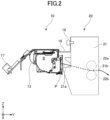
- a printer 10 is, for example, a thermal printer, and is installed in an ATM (Automated Teller Machine), a ticket vending machine, a kiosk terminal, or the like.
- ATM Automatic Teller Machine
- the type of the printer is not limited to a thermal printer, and other printers such as an inkjet printer and a laser printer may be used as well.
- the printer 10 has a thermal head 11, a platen roller 12, a motor 13, a movable blade 14, a fixed blade 15, a frame 16, and a control substrate 17.
- the printer 10 sandwiches a recording sheet P between the thermal head 11 and the platen roller 12, and prints on the recording sheet P by feeding the recording paper P by the rotation of the platen roller 12, and by pressing the recording sheet P against the thermal head 11.
- the motor 13 rotates the platen roller 12.
- the movable blade 14 and the fixed blade 15 constitute a cutter, and the recording sheet P is cut by moving the movable blade 14 toward the fixed blade 15.
- the control substrate 17 is attached to the frame 16.
- the control substrate 17 controls the operation of the printer 10.
- the X direction is the width direction of the sheet
- the Z direction is the vertical direction with respect to the sheet surface.
- the applying unit 20 has a housing 21, rollers 22, a gear array 23, a motor 24, a pressing portion 25, a sensor 26, an applying portion 27, and a control device 28.
- the housing 21 accommodates the rollers 22, the gear array 23, the motor 24, the pressing portion 25, the sensor 26, the applying portion 27, and the control device 28.
- the frame 16 is screwed to the housing 21 with a screw 18.
- the applying unit 20 is connected to the printer 10.
- the housing 21 includes a feed port 21a and a discharge port 21b.
- the feed port 21a is an opening for carrying the recording sheet P, discharged from the printer 10, into the housing 21.
- the discharge port 21b is an opening for discharging the recording sheet P to the outside of the housing 21.
- the rollers 22 transport the recording sheet P discharged from the printer 10.
- the rollers 22 include upper rollers 22a and lower rollers 22b.
- a pair of upper rollers 22a are provided near both widthwise ends of the recording sheet P.
- a pair of lower rollers 22b are provided below the upper rollers 22a so as to be in contact with the upper rollers 22a.
- the lower rollers 22b are connected to the motor 24 via the gear array 23. By rotating the motor 24, the gear array 23 also rotates, and this rotation is transmitted to rotate the lower rollers 22b.
- both end portions of the recording paper P are sandwiched between the upper rollers 22a and the lower rollers 22b, and discharged out of the housing 21 from the discharge port 21b.
- the upper rollers 22a may be rotated by connecting the motor to the upper rollers 22a via the gear array.
- the upper rollers 22a and the lower rollers 22b may also be rotated by connecting the motor to both the upper rollers 22a and the lower rollers 22b via the gear array.
- the gear array 23 includes a plurality of gears, and transmits the power of the motor 24 to the lower rollers 22b.
- the motor 24 rotates the lower rollers 22b via the gear array 23.
- the rotation of the motor 24 is controlled based on commands from the control device 28.
- the motor 24 is, for example, a servo motor.
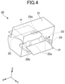
- the pressing portion 25 is provided on the transport path of the recording sheet P between the feed port 21a and the rollers 22.
- the recording sheet P to be transported by the rollers 22 is preloaded by the pressing portion 25 in a direction away from the sensor 26 and pressed in the +Z direction, thereby causing the recording sheet P to bend.
- the pressing portion 25 is provided with an opening 25a, so that the light projected by the sensor 26 can pass therethrough.
- the shape of the opening 25a is, for example, rectangular.
- the pressing portion 25 is, for example, a leaf spring.
- the sensor 26 is, for example, a photoelectric sensor, and provided at a position corresponding to the opening 25a.
- the sensor 26 projects light toward the opening 25a, detects the light reflected by the recording sheet P, converts the changes in the amount of detected light into a voltage signal, and transmits the voltage signal to the control device 28.
- FIG. 7 is a diagram illustrating an example of the sensor's output waveform, where the horizontal axis is the distance from the sensor 26 to the recording sheet P, and the vertical axis is the voltage output by the sensor 26 (sensor voltage). As shown in FIG.
- the sensor 26 has a characteristic of showing the maximum value when the distance from the sensor 26 to the recording sheet P is equal to a distance d, which is the distance from the sensor 26 to the +Z-side wall of the transport path(see FIG. 5 ).
- a distance d which is the distance from the sensor 26 to the +Z-side wall of the transport path(see FIG. 5 ).
- the sensor voltage becomes smaller than when the distance from the sensor 26 to the recording sheet P is d.
- the above-described characteristic of the sensor 26 is by no means limiting, and, for example, the sensor 26 may have a characteristic in which the sensor voltage decreases or increases as the distance from the sensor 26 to the recording sheet P increases.
- the applying portion 27 is provided between the pair of lower rollers 22b.
- the applying portion 27 applies an adhesive to the lower surface of the recording sheet P transported by the rollers 22.
- the applying portion 27 includes a holding portion 27a, an adhesive portion 27b, and a pressing portion 27c.
- the holding portion 27a holds the adhesive portion 27b exposed upward (facing the recording sheet P).
- the adhesive portion 27b is a solid adhesive. However, the adhesive portion 27b may be a liquid adhesive as well.
- the pressing portion 27c presses the holding portion 27a upward, so as to press the adhesive portion 27b against the lower surface of the recording sheet P and apply the adhesive.
- the pressing portion 27c is, for example, a coil spring.
- the control device 28 adjusts the rotation speed of the lower rollers 22b according to the detection value of the sensor 26.
- the control device 28 includes a determining portion 28a, a storage portion 28b, and a control portion 28c.
- the determining portion 28a determines that the recording sheet P is in the applying unit 20.
- the detection value of the sensor 26 is equal to or greater than a presence determining value
- the determining portion 28a determines that the recording sheet P is in the applying unit 20.
- the presence determining value is a preset value.
- the determining portion 28a determines that the recording sheet P is bent.
- the determining portion 28a determines that the recording sheet P is not bent or is bent only a little.
- the bend determining value is a preset value, set to a larger value than the presence determining value, and set to a smaller value than the sensor voltage when the recording sheet P is present at a position corresponding to the distance d.
- the storage portion 28b stores various information.
- the various information includes the presence determining value and the bend determining value.
- the control portion 28c adjusts the rotation speed of the lower rollers 22b based on the determination result of the determining portion 28a.
- the control portion 28c stops the lower rollers 22b by stopping the motor 24.
- the control portion 28c increases the rotation speed of the motor 24 according to the difference between the sensor voltage and the bend determining value, and rotates the lower rollers 22b at a higher speed.
- the transport speed of the recording sheet P in the applying unit 20 becomes closer to the transport speed in the printer 10, and the bend of the recording sheet P becomes smaller.
- the control portion 28c slows down the rotation speed of the motor 24 according to the difference between the sensor voltage and the bend determining value, and rotates the lower rollers 22b at a lower speed. By this means, the transport speed in the applying unit 20 becomes closer to the transport speed in the printer 10.
- FIG. 9A to FIG. 14B are diagrams for explaining the states of the applying unit 20, in which the printer 10 prints on the recording sheet P, the applying unit 20 applies an adhesive to the recording sheet P, and the recording sheet P is discharged from the applying unit 20.
- each "A" diagram is a schematic view that illustrates an internal structure of the applying unit 20, and each "B" diagram is a view that illustrates the detected values of the sensor 26.
- FIGs. 9A and 9B are diagrams for explaining the state of the applying unit 20 when the printer 10 starts operating.
- FIG. 9A no the recording sheet P has been transported to the rollers 22 of the applying unit 20 when the printer 10 starts operating.
- the sensor 26 outputs a voltage value V1 that is smaller than a presence determining value Vth1.
- the control device 28 determines that the recording sheet P is not present in the applying unit 20, based on the output of the sensor 26.
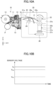
- FIGs. 10A and 10B are diagrams for explaining the state of the applying unit 20 when the recording sheet P is passed from the printer 10 onto the applying unit 20.
- the recording sheet P is passed from the printer 10 onto the applying unit 20
- the recording sheet P is pressed by the pressing portion 25 in a direction away from the sensor 26, and therefore the distance from the sensor 26 to the recording sheet P becomes d, and the recording sheet P is transported in the direction of the rollers 22.
- the sensor 26 outputs a voltage value V2, which is larger than a presence determining value Vth1 and a bend determining value Vth2.
- the control device 28 determines that the recording sheet P is present in the applying unit 20 and that the recording sheet P is bent. Also, in accordance with this determination result, the control device 28 increases the rotation speed of the motor 24 to rotate the lower rollers 22b at a higher speed and reduce the bend of the recording sheet P.
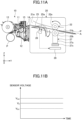
- FIG. 11 is a diagram for explaining the state of the applying unit 20 when the transport speed of the recording sheet P in the applying unit 20 is higher than the transport speed in the printer 10.
- the recording sheet P is pulled by the rollers 22, so that the pressing portion 25 is pressed downward in the -Z direction, and the recording sheet P approaches the sensor 26.
- the sensor 26 outputs a voltage value V3 that is larger than presence determining value Vth1 and smaller than bend determining value Vth2.
- the control device 28 determines that the recording sheet P is present in the applying unit 20 and that the recording sheet P is not bent or is bent only a little. Also, in accordance with this determination result, the control device 28 lowers the rotation speed of the motor 24 to rotate the lower rollers 22b at a lower speed. By this means, the transport speed in the applying unit 20 becomes closer to the transport speed in the printer 10, and the bend of the recording sheet P becomes smaller.
- the applying portion 27 applies an adhesive A to the recording sheet P, and the recording sheet P is transported toward the discharge port 21b.
- FIGs. 12A and 12B are diagrams for explaining the state of the applying unit 20 when the transport speed of the recording sheet P in the applying unit 20 is slower than the transport speed of the recording sheet P in the printer 10.
- FIG. 12A in the event the transport speed in the applying unit 20 is slower than the transport speed in the printer 10, the tension of the recording sheet P between the printer 10 and the rollers 22 weakens, and the recording sheet P is pressed by the pressing portion 25 in a direction away from the sensor 26. Consequently, the recording sheet P moves away from the sensor 26.
- the sensor 26 outputs a voltage value V4 that is greater than presence determining value Vth1 and bend determining value Vth2.
- the control device 28 determines that the recording sheet P is in the applying unit 20 and that the recording sheet P is bent. Also, in accordance with this determination result, the control device 28 receives and increases the rotation speed of the motor 24 to rotate the lower rollers 22b at a higher speed. By this means, the transport speed in the applying unit 20 becomes closer to the transport speed in the printer 10.
- the control device 28 thus repeatedly controls the rotation speed of the motor 24 shown in FIGs. 11A and 11B and FIGs. 12A and 12B while the recording sheet P is transported by the rollers 22.
- the transport speed in the applying unit 20 can be made to follow the transport speed in the printer 10.
- the recording sheet P can be uniformly coated with the adhesive. That is, it is possible to provide a highly versatile applying unit 20 that can be retrofitted to various printers without necessitating complex control.
- FIGs. 13A and 13B are diagrams for explaining the state of the applying unit 20 when the recording sheet P is cut in the printer 10.
- the recording sheet P is cut, the recording sheet P is pressed by the pre-loading of the pressing portion 25 in a direction away from the sensor 26, and so the distance from the sensor 26 to the recording sheet P is d.
- the sensor 26 outputs a voltage value V5 that is greater than presence determining value Vth1 and bend determining value Vth2.
- the control device 28 determines that the recording sheet P is in the applying unit 20 and that the recording sheet P is bent.
- control device 28 increases the rotation speed of the motor 24 to a higher speed than shortly before the recording sheet P is cut, so as to rotate the lower rollers 22b at a higher speed.
- the recording sheet P coated with the adhesive A is discharged from the discharge port 21b.
- FIGs. 14A and 14B are diagrams for explaining the state of the applying unit 20 when the recording sheet P is discharged from the applying unit 20.
- the recording sheet P is not at the detection position of the sensor 26. Consequently, as shown in FIG. 14B , the sensor 26 outputs a voltage value V6 that is smaller than presence determining value Vth1.
- the control device 28 determines that the recording sheet P is not in the applying unit 20. Also, in accordance with this determination result, the control device 28 transports the recording sheet P for a distance that is longer than the distance from the sensor 26 to the rollers 22, and then stops the rotation of the lower rollers 22b. Note that it is also possible to stop the recording sheet P at a position where the rollers 22 grip the recording sheet P, and let the user pull out the recording sheet P.
- a label sheet is created, the upper surface of which is printed, and the lower surface of which is coated with the adhesive A.
- the control device 28 adjusts the rotation speed of the rollers 22 in accordance with the bend of the recording sheet P discharged from the printer 10, the bend being detected by the sensor 26.
- the transport speed of the recording sheet P in the applying unit 20 can be made to follow the transport speed in the printer 10. Therefore, even when the applying unit 20 is connected to the printer, it is still possible to apply an adhesive to the recording sheet P. That is, it is possible to provide a highly versatile applying unit 20 that can be retrofitted to various printers without necessitating complex control such as synchronizing the printer and the applying unit.
- the applying unit 20 of this embodiment applies an adhesive to the recording sheet P after the recording sheet P is cut in the printer 10. That is, when the recording sheet P is cut, the adhesive is not transferred to the recording sheet P yet, so that no adhesive sticks to the movable blade 14 and the fixed blade 15 of the printer 10. As a result of this, the frequency of cleaning and replacing the movable blade 14 and fixed blade 15 can be reduced.
- control device 28 determines the presence or absence of the recording sheet P and adjusts the transport speed of the lower rollers 22b based on the detection value obtained by one sensor 26, so that the number of parts does not increase.
- an adhesive is transferred to the recording sheet P by pressing the adhesive portion 27b against the recording sheet P being transported by the rollers 22 and thus applying the adhesive to the recording sheet P.
- any commercially available solid adhesives and liquid adhesives can be used, without using special adhesives such as adhesive tapes.
- the present invention is by no means limited to this.
- another sensor such as a mechanical sensor may be used to detect the bend of the recording sheet.
- the applying portion applied adhesive to the lower surface of the recording sheet in the case described in the above embodiment, the present invention is by no means limited to this.
- the applying portion may be provided between a pair of upper rollers and apply an adhesive to the upper surface of the recording sheet transported by the rollers.
- the applying portion was provided separately from the rollers in the case described in the above embodiment, the present invention is by no means limited to this.
- the upper rollers themselves and/or the lower rollers themselves may be configured as adhesive portions.
Landscapes
- Controlling Sheets Or Webs (AREA)
- Physics & Mathematics (AREA)
- General Physics & Mathematics (AREA)
- Handling Of Sheets (AREA)
- Controlling Rewinding, Feeding, Winding, Or Abnormalities Of Webs (AREA)
- Folding Of Thin Sheet-Like Materials, Special Discharging Devices, And Others (AREA)
- Delivering By Means Of Belts And Rollers (AREA)
Applications Claiming Priority (1)
| Application Number | Priority Date | Filing Date | Title |
|---|---|---|---|
| JP2022037735A JP2023132424A (ja) | 2022-03-11 | 2022-03-11 | 塗布ユニット |
Publications (1)
| Publication Number | Publication Date |
|---|---|
| EP4242003A1 true EP4242003A1 (de) | 2023-09-13 |
Family
ID=84820067
Family Applications (1)
| Application Number | Title | Priority Date | Filing Date |
|---|---|---|---|
| EP23150247.7A Pending EP4242003A1 (de) | 2022-03-11 | 2023-01-04 | Auftragseinheit |
Country Status (3)
| Country | Link |
|---|---|
| EP (1) | EP4242003A1 (de) |
| JP (1) | JP2023132424A (de) |
| CN (1) | CN116727168A (de) |
Citations (8)
| Publication number | Priority date | Publication date | Assignee | Title |
|---|---|---|---|---|
| JP2001018478A (ja) | 1999-07-08 | 2001-01-23 | Nisca Corp | 印刷シートに添着性を付与する画像形成装置およびこの画像形成装置用のシート積載装置 |
| EP1388421B1 (de) * | 2002-08-05 | 2006-12-27 | Seiko Instruments Inc. | Vorrichtung zur thermischen Aktivierung von wärmeempfindlicher Klebefolie und Drucker |
| JP2011235595A (ja) | 2010-05-13 | 2011-11-24 | Seiko Epson Corp | 粘着剤付加ユニットおよびプリンター、ならびに粘着ラベルの作成方法 |
| US20120249713A1 (en) * | 2011-03-28 | 2012-10-04 | Yoshinori Sato | Adhesive label issuing device and printer |
| JP2014097851A (ja) | 2012-11-13 | 2014-05-29 | Seiko Epson Corp | 記録装置、粘着剤付加装置、及び印刷システム |
| US20140373775A1 (en) * | 2012-05-09 | 2014-12-25 | Seiko Epson Corporation | Adhesive label production device |
| JP2020019582A (ja) | 2018-07-30 | 2020-02-06 | スター精密株式会社 | 粘着剤転写機構及びプリンタ |
| EP3240693B1 (de) * | 2014-12-29 | 2020-09-23 | Custom S.p.A. | Druckvorrichtung |
Family Cites Families (4)
| Publication number | Priority date | Publication date | Assignee | Title |
|---|---|---|---|---|
| JPS62108098A (ja) * | 1985-11-06 | 1987-05-19 | 株式会社学習研究社 | メモ用紙の製造方法 |
| JP2004058518A (ja) * | 2002-07-30 | 2004-02-26 | Noritsu Koki Co Ltd | 画像形成装置 |
| JP2012041182A (ja) * | 2010-08-23 | 2012-03-01 | Seiko Epson Corp | 搬送装置、記録装置及び搬送方法 |
| CN112455116B (zh) * | 2020-11-17 | 2021-10-01 | 曹雪松 | 一种会计用自动点胶装置 |
-
2022
- 2022-03-11 JP JP2022037735A patent/JP2023132424A/ja active Pending
-
2023
- 2023-01-04 EP EP23150247.7A patent/EP4242003A1/de active Pending
- 2023-02-22 CN CN202310149783.9A patent/CN116727168A/zh active Pending
Patent Citations (8)
| Publication number | Priority date | Publication date | Assignee | Title |
|---|---|---|---|---|
| JP2001018478A (ja) | 1999-07-08 | 2001-01-23 | Nisca Corp | 印刷シートに添着性を付与する画像形成装置およびこの画像形成装置用のシート積載装置 |
| EP1388421B1 (de) * | 2002-08-05 | 2006-12-27 | Seiko Instruments Inc. | Vorrichtung zur thermischen Aktivierung von wärmeempfindlicher Klebefolie und Drucker |
| JP2011235595A (ja) | 2010-05-13 | 2011-11-24 | Seiko Epson Corp | 粘着剤付加ユニットおよびプリンター、ならびに粘着ラベルの作成方法 |
| US20120249713A1 (en) * | 2011-03-28 | 2012-10-04 | Yoshinori Sato | Adhesive label issuing device and printer |
| US20140373775A1 (en) * | 2012-05-09 | 2014-12-25 | Seiko Epson Corporation | Adhesive label production device |
| JP2014097851A (ja) | 2012-11-13 | 2014-05-29 | Seiko Epson Corp | 記録装置、粘着剤付加装置、及び印刷システム |
| EP3240693B1 (de) * | 2014-12-29 | 2020-09-23 | Custom S.p.A. | Druckvorrichtung |
| JP2020019582A (ja) | 2018-07-30 | 2020-02-06 | スター精密株式会社 | 粘着剤転写機構及びプリンタ |
Also Published As
| Publication number | Publication date |
|---|---|
| CN116727168A (zh) | 2023-09-12 |
| US20230286009A1 (en) | 2023-09-14 |
| JP2023132424A (ja) | 2023-09-22 |
Similar Documents
| Publication | Publication Date | Title |
|---|---|---|
| US7997676B2 (en) | Image recording apparatus | |
| KR100775452B1 (ko) | 프린터 | |
| US5566906A (en) | Decurling device for a rolled recording paper | |
| US6602008B2 (en) | Print-medium transport unit | |
| US20160124687A1 (en) | Printing Device and Control Method of a Printing Device | |
| US10787009B2 (en) | Printing apparatus | |
| US20200039253A1 (en) | Printing apparatus | |
| US20210362520A1 (en) | Printer | |
| US8066278B2 (en) | Printer | |
| EP4242003A1 (de) | Auftragseinheit | |
| EP2918418A2 (de) | Bilderzeugungsvorrichtung | |
| US12616993B2 (en) | Applying unit | |
| US11691842B2 (en) | Image forming apparatus | |
| US7165902B2 (en) | Printer and printer control method | |
| US7500666B2 (en) | Recording medium feeding apparatus, recording apparatus, liquid ejecting apparatus | |
| US20130084120A1 (en) | Hybrid printer-feeder mechanism | |
| JP4816542B2 (ja) | インクジェット記録装置 | |
| US9061519B2 (en) | Printer apparatus and printing method | |
| EP2927006A1 (de) | Drucker | |
| US8020986B2 (en) | Image recording apparatus | |
| JP2003112458A (ja) | 記録装置 | |
| JP2004043095A (ja) | 記録装置および被記録材搬送用トレイ | |
| CN110549733B (zh) | 图像打印设备 | |
| JP2001105678A (ja) | プリンタ及びその制御方法 | |
| JP2005254733A (ja) | プリンタ及びプリンタの制御方法 |
Legal Events
| Date | Code | Title | Description |
|---|---|---|---|
| PUAI | Public reference made under article 153(3) epc to a published international application that has entered the european phase |
Free format text: ORIGINAL CODE: 0009012 |
|
| STAA | Information on the status of an ep patent application or granted ep patent |
Free format text: STATUS: THE APPLICATION HAS BEEN PUBLISHED |
|
| AK | Designated contracting states |
Kind code of ref document: A1 Designated state(s): AL AT BE BG CH CY CZ DE DK EE ES FI FR GB GR HR HU IE IS IT LI LT LU LV MC ME MK MT NL NO PL PT RO RS SE SI SK SM TR |
|
| STAA | Information on the status of an ep patent application or granted ep patent |
Free format text: STATUS: REQUEST FOR EXAMINATION WAS MADE |
|
| 17P | Request for examination filed |
Effective date: 20230908 |
|
| RBV | Designated contracting states (corrected) |
Designated state(s): AL AT BE BG CH CY CZ DE DK EE ES FI FR GB GR HR HU IE IS IT LI LT LU LV MC ME MK MT NL NO PL PT RO RS SE SI SK SM TR |
|
| STAA | Information on the status of an ep patent application or granted ep patent |
Free format text: STATUS: EXAMINATION IS IN PROGRESS |
|
| 17Q | First examination report despatched |
Effective date: 20240822 |