EP4241997A1 - Liquid discharge head and liquid discharge apparatus - Google Patents
Liquid discharge head and liquid discharge apparatus Download PDFInfo
- Publication number
- EP4241997A1 EP4241997A1 EP23159596.8A EP23159596A EP4241997A1 EP 4241997 A1 EP4241997 A1 EP 4241997A1 EP 23159596 A EP23159596 A EP 23159596A EP 4241997 A1 EP4241997 A1 EP 4241997A1
- Authority
- EP
- European Patent Office
- Prior art keywords
- liquid discharge
- liquid
- housing member
- discharge head
- ground
- Prior art date
- Legal status (The legal status is an assumption and is not a legal conclusion. Google has not performed a legal analysis and makes no representation as to the accuracy of the status listed.)
- Granted
Links
Images



Classifications
-
- B—PERFORMING OPERATIONS; TRANSPORTING
- B41—PRINTING; LINING MACHINES; TYPEWRITERS; STAMPS
- B41J—TYPEWRITERS; SELECTIVE PRINTING MECHANISMS, i.e. MECHANISMS PRINTING OTHERWISE THAN FROM A FORME; CORRECTION OF TYPOGRAPHICAL ERRORS
- B41J2/00—Typewriters or selective printing mechanisms characterised by the printing or marking process for which they are designed
- B41J2/005—Typewriters or selective printing mechanisms characterised by the printing or marking process for which they are designed characterised by bringing liquid or particles selectively into contact with a printing material
- B41J2/01—Ink jet
- B41J2/135—Nozzles
- B41J2/14—Structure thereof only for on-demand ink jet heads
- B41J2/14201—Structure of print heads with piezoelectric elements
-
- B—PERFORMING OPERATIONS; TRANSPORTING
- B41—PRINTING; LINING MACHINES; TYPEWRITERS; STAMPS
- B41J—TYPEWRITERS; SELECTIVE PRINTING MECHANISMS, i.e. MECHANISMS PRINTING OTHERWISE THAN FROM A FORME; CORRECTION OF TYPOGRAPHICAL ERRORS
- B41J2/00—Typewriters or selective printing mechanisms characterised by the printing or marking process for which they are designed
- B41J2/005—Typewriters or selective printing mechanisms characterised by the printing or marking process for which they are designed characterised by bringing liquid or particles selectively into contact with a printing material
- B41J2/01—Ink jet
- B41J2/135—Nozzles
- B41J2/14—Structure thereof only for on-demand ink jet heads
- B41J2002/14491—Electrical connection
-
- B—PERFORMING OPERATIONS; TRANSPORTING
- B41—PRINTING; LINING MACHINES; TYPEWRITERS; STAMPS
- B41J—TYPEWRITERS; SELECTIVE PRINTING MECHANISMS, i.e. MECHANISMS PRINTING OTHERWISE THAN FROM A FORME; CORRECTION OF TYPOGRAPHICAL ERRORS
- B41J2202/00—Embodiments of or processes related to ink-jet or thermal heads
- B41J2202/01—Embodiments of or processes related to ink-jet heads
- B41J2202/05—Heads having a valve
Definitions
- the disclosures herein relate to a liquid discharge head and a liquid discharge apparatus.
- an ink-jet type image forming apparatus that forms an image by discharging ink to paper or the like is known.
- the liquid discharge head In such an image forming apparatus, if electric charge such as static electricity is accumulated in a liquid discharge head that discharges ink, the printing quality may be adversely affected. Therefore, in order to remove the accumulated electric charge, the liquid discharge head is often provided with a ground member.
- Patent Document 1 Japanese Unexamined Patent Application Publication No. 2013-151094 ) describes a configuration in which a ground member contacts the outer side of a liquid discharge head.
- Patent Document 1 Japanese Unexamined Patent Application Publication No. 2013-151094
- a liquid discharge head includes a nozzle forming member having a nozzle configured to discharge liquid; an opening and closing member configured to open and close the nozzle; a piezoelectric body configured to expand and contract in an axial direction in response to a drive voltage so as to actuate the opening and closing member such that the nozzle is opened and closed; a first housing member having a cylindrical shape and configured to house the piezoelectric body; and a ground member configured to contact an inner side of the first housing member.
- the grounding of a liquid discharge head can be maintained satisfactorily.
- FIG. 1 is a diagram illustrating the configuration of the painting apparatus 201 according to an embodiment.
- FIG. 2 is a diagram illustrating an example arrangement of the painting apparatus 201 with respect to an automobile M that is a printing target.
- FIG. 3 is a diagram illustrating another example arrangement of the painting apparatus 201 with respect to the automobile M that is the printing target.
- the painting apparatus 201 includes a print head 202, an X-Y table 203, a camera 204, a control unit 209, a driver 211, and the like.
- the print head 202 is a liquid discharge head that discharges paint (liquid) toward the painting target surface of a painting target object M.
- the print head 202 includes a plurality of valve nozzles, and the paint is discharged from each of the valve nozzles in a direction perpendicular to the paint discharge surface of the print head 202. That is, the paint discharge surface of the print head 202 is parallel to an X-Y plane formed by the movement of the X-Y table 203, and paint dots discharged from the valve nozzles are discharged in a direction perpendicular to the X-Y plane. The directions in which the paint is discharged from the valve nozzles are parallel to each other.
- Each of the valve nozzles is coupled to a paint tank of a predetermined color.
- the ink tank is pressurized by a pressurizing device, so that paint dots can be discharged onto the printing target surface of the painting target object M without any problem as long as the distance between each of the valve nozzles and the printing target surface is approximately 50
- the X-Y table 203 includes a mechanism for moving the print head 202 and the camera 204 in the X direction and the Y direction that are orthogonal to each other.
- the X-Y table 203 includes an X-axis movement mechanism 205 and a Y-axis movement mechanism 206.
- the X-axis movement mechanism 205 moves a slider that holds the print head 202 and the camera 204, which will be described later, in the X direction
- the Y-axis movement mechanism 206 moves the X-axis movement mechanism 205 in the Y direction while holding the X-axis movement mechanism 205 by two arms.
- a shaft 207 is provided on the Y-axis movement mechanism 206.
- the shaft 207 is held and driven by a robot arm 208 such that the print head 202 can be freely arranged at a predetermined position where printing is to be performed on the painting target object M.
- the print head 202 can be arranged at an upper position of the automobile as illustrated in FIG. 2 or at a side position of the automobile as illustrated in FIG. 3 .
- the operation of the robot arm 208 is controlled based on a program that is stored in the control unit 209 in advance.
- the camera 204 is an image capturing device, such as a digital camera, that captures images of the printing target surface of the painting target object M.
- the camera 204 captures images of a predetermined range of the printing target surface of the painting target object M at fixed fine intervals while moving in the X direction and the Y direction by the X-axis movement mechanism 205 and the Y-axis movement mechanism 206. Specifications of lenses, resolution, and the like of the camera 204 are appropriately selected, such that the camera 204 can capture a plurality of sub-divided images of the predetermined range of the printing target surface.
- the camera 204 captures a plurality of sub-divided images of the printing target surface continuously and automatically as controlled by the control unit 209, which will be described later.
- the control unit 209 moves the X-Y table 203 based on image editing software S for editing an image captured by the camera 204 and a preset control program so as to control the printing operation (paint discharging operation) of the print head 202.
- the control unit 209 is constituted by what is known as a microcomputer.
- the control unit 209 includes a storage device that records and stores various programs, data of captured images, data of images to be printed, and the like, a central processing unit that executes various processes according to programs, and input devices such as a keyboard and a mouse.
- the control unit 209 includes a digital versatile disc (DVD) player and the like as necessary.
- the control unit 209 includes a monitor 210.
- the monitor 210 displays information input into the control unit 209, results processed by the control unit 209, and the like.
- the control unit 209 uses image processing software to perform image processing on a plurality of pieces of sub-divided image data captured by the camera 204, and generates a composite print surface obtained by projecting the printing target surface of the painting target object M, which is not planar, onto a plane. Further, the control unit 209 superimposes, on the composite print surface, a rendering target image A that is to be printed such that the rendering target image A is continuous with an image already printed on the printing target surface, and edits the rendering target image A such that the rendering target image A is continuous with the edge portion of the already-printed image, thereby generating an edited image B.
- FIG. 4 is a cross-sectional view illustrating an overall configuration of the print head according to the embodiment.
- FIG. 5 is a partially enlarged cross-sectional view of the print head of FIG. 4 .
- the print head 202 is a valve-type liquid discharge head.
- the print head 202 includes a nozzle plate 22 that serves as a nozzle forming member having a nozzle 22a (discharge port) configured to discharge paint (liquid), a liquid chamber 23, a needle 21 that serves as an opening and closing member configured to open and close the nozzle 22a, a piezoelectric body 9, a piezoelectric frame 8, an outer housing 1 that serves as a first housing member, and an inner housing 2 that serves as a second housing member.
- the outer housing 1 is a member that has a cylindrical shape and houses the needle 21, the piezoelectric body 9, the piezoelectric frame 8, the inner housing 2, and the like.
- the nozzle plate 22 is provided at the left end, as viewed in FIG. 4 , of the outer housing 1 via the liquid chamber 23.
- the liquid chamber 23 is provided with a liquid flow channel 27, and the paint is supplied from the outside into the liquid chamber 23 through the liquid flow channel 27.
- the piezoelectric frame 8 holds the piezoelectric body 9 so as to sandwich both ends in the longitudinal direction of the piezoelectric body 9.
- the right end, as viewed in FIG. 4 , of the piezoelectric frame 8 is positioned with respect to the inner housing 2 and is fixed to the inner housing 2.
- the needle 21 is supported on the left end, as viewed in FIG. 4 , of the piezoelectric frame 8.
- a cornice-shaped deformable part 8a that can expand and contract in the axial direction of the housing 1 (in the horizontal direction in FIG. 4 ) is provided in the vicinity of the left end, as viewed in FIG. 4 , of the piezoelectric frame 8.
- the deformable part 8a When the piezoelectric body 9 expands and contracts in the axial direction in response to the application of a drive voltage, the deformable part 8a also expands and contracts in the axial direction. As a result, the needle 21 supported by the piezoelectric frame 8 is moved in the axial direction, and the nozzle 22a is opened and closed by the needle 21. As illustrated in FIG. 4 , in a state in which the needle 21 is moved rightward and the nozzle 22a is opened, the paint within the liquid chamber 23 is discharged from the nozzle 22a.
- the inner housing 2 is formed in a cylindrical shape, and a lead wire 4 that serves as a supply wire for supplying the drive voltage to the piezoelectric body 9 is inserted through the inner housing 2.
- the piezoelectric body 9 is electrically connected to an external power source via the lead wire 4, and the drive voltage is applied from the power source to the piezoelectric body 9 via the lead wire 4.
- the inner housing 2 includes a frame positioning portion 2b on the inside (inner wall) of the inner housing 2.
- the frame positioning portion 2b positions the piezoelectric frame 8.
- the right end, as viewed in FIG. 5 , of the piezoelectric frame 8 is inserted into the inner housing 2 and contacts the frame positioning portion 2b, thereby causing the piezoelectric frame 8 to be positioned axially with respect to the inner housing 2.
- a ground wire (an earth wire) 3 that is electrically connected to an external grounding point is inserted into the inner housing 2.
- the ground wire 3 is held together with the lead wire 4 by a binding heat-shrink tube 6 that serves as a holding member housed in the inner housing 2.
- the ground wire 3 and the lead wire 4 are supported by a wiring support disk 11 that serves as a support member housed in the inner housing 2.
- the wiring support disk 11 has a hole 11a in the center thereof and a hole 11b on the outer diameter side relative to the hole 11a.
- the ground wire 3 is inserted through the hole 11a, and the lead wire 4 is inserted through the hole 11b.
- a part located on the right side relative to the wiring support disk 11, that is, a part including the binding heat-shrink tube 6 is filled with a resin 5.
- the ground wire 3 is constituted by a conductive wire and an insulating portion that covers the conductive wire.
- the left end, as viewed in FIG. 5 , of the ground wire 3 serves as an exposed portion 7 where the conductive wire is exposed.
- the exposed portion 7 is electrically connected to a leaf spring 10 that servers as a ground member.
- the leaf spring 10 includes a ground wire connector 10a disposed in the inner housing 2.
- the exposed portion 7 is electrically connected to the ground wire connector 10a.
- the leaf spring 10 is attached to and supported by the inner housing 2. As illustrated in FIG. 5 , in a state in which the leaf spring 10 is attached to the inner housing 2, a contact portion 10b of the leaf spring 10 is disposed on a grooved portion 2a provided on the outer peripheral surface of the inner housing 2. Further, the contact portion 10b of the leaf spring 10 is interposed between the inner housing 2 and the outer housing 1 while being elastically deformed, and the leaf spring 10 (contact portion 10b) resiliently contacts the outer peripheral surface (grooved portion 2a) of the inner housing 2 and the inner peripheral surface of the outer housing 1 by the resilient preload of the contact portion 10b.
- the leaf spring 10 which serves as the ground member, resiliently contacts both the outer housing 1 and the inner housing 2, thereby causing the outer housing 1 and the inner housing 2 to be electrically connected (grounded) to the external grounding point via the leaf spring 10 and the ground wire 3. Accordingly, even if electric charge is accumulated in the outer housing 1 and the inner housing 2, the accumulated electric charge can be removed via the leaf spring 10 and the ground wire 3.
- the leaf spring 10 which serves as the ground member, is housed in the outer housing 1. Therefore, even if an external shock or vibration is applied to the print head, the leaf spring 10 can be prevented from being damaged or falling off from the print head. Accordingly, the grounding of the print head can be maintained satisfactorily.
- the leaf spring 10 is attached to the inner housing 2, the leaf spring 10 and the inner housing 2 can be integrally inserted into and removed from the outer housing 1. As described, in the print head according to the present embodiment, since the leaf spring 10 and the inner housing 2 are integrally insertable into and removable from the outer housing 1, work of replacing housing components including the leaf spring 10 can be easily performed.
- the inner housing 2 to which the leaf spring 10 is attached also serves as a member for positioning the piezoelectric body 9 and the piezoelectric frame 8. Therefore, when the inner housing 2 is inserted into the outer housing 1, both the grounding of the outer housing 1 and the inner housing 2 and the positioning of the piezoelectric body 9 and the piezoelectric frame 8 can be performed.
- the piezoelectric body 9 and the piezoelectric frame 8 are inserted into the outer housing 1, and subsequently, the inner housing 2, to which the leaf spring 10 is attached, is inserted into the outer housing 1 from the right side toward the left side as viewed in FIG. 5 .
- the outer housing 1 and the inner housing 2 are grounded via the leaf spring 10 and also the piezoelectric body 9 and the piezoelectric frame 8 are positioned. Accordingly, with the configuration according to the present embodiment, grounding work and assembly work of the print head can be simplified.
- the ground wire 3 and the lead wire 4 are supported by the wiring support disk 11, thereby preventing the ground wire 3 and the lead wire 4 from being displaced in the inner housing 2 and contacting surrounding members such as the inner housing 2. Further, as viewed in a direction in which the inner housing 2 is inserted into the outer housing 1 (as viewed from the right side in FIG. 5 ), the ground wire 3 and the lead wire 4 are supported by the wiring support disk 11 at mutually different positions (without contacting each other). Therefore, the ground wire 3 and the lead wire 4 can be reliably prevented from contacting each other.
- the ground wire 3 and the lead wire 4 are supported so as not to contact each other or other surrounding members. Therefore, the ground wire 3 (exposed portion 7) can be prevented from falling off from the ground wire connector 10a of the leaf spring 10 and resulting in poor grounding, and also, poor connection between the lead wire 4 and the piezoelectric body 9 can be prevented. Accordingly, in the print head according to the present embodiment, the grounding of the outer housing 1 and the inner housing 2 and an electrical connection between the piezoelectric body 9 and the power source can be satisfactorily ensured.
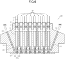
- FIG. 6 is a cross-sectional view illustrating a configuration of a head unit including liquid discharge heads according to an embodiment.
- a head unit 20 includes a plurality of (in the example illustrated in FIG. 6 , eight) liquid discharge heads 30, a liquid supply channel 32 for supplying paint (liquid) to the liquid discharge heads 30, a liquid supply port 33 for supplying the paint to the liquid supply channel 32, and a liquid discharge port 34 for discharging the paint from the liquid supply channel 32.
- the basic configuration of the plurality of liquid discharge heads 30 is the same as that described with reference to FIGS. 4 and 5 , and components corresponding to those of FIGS. 4 and 5 are denoted by the same reference numerals in FIG. 6 .
- the eight liquid discharge heads 30 are provided such that respective nozzles (discharge ports) 22a are arranged at substantially equal intervals in one direction (in the horizontal direction in FIG. 6 ).
- the liquid discharge heads 30 extend in the vertical direction so as to discharge paint downward from the respective nozzles 22a on the lower side of FIG. 6 .
- Each of the liquid discharge heads 30 is rotated by substantially 90 degrees counterclockwise from the state illustrated in FIG. 4 , centering on the nozzle 22a side.
- the liquid supply channel 32 is provided such that the liquid supply channel 32 penetrates through liquid chambers 23 of the respective liquid discharge heads 30, thereby enabling paint to flow from one side (the left side of FIG. 6 ) to the other side (the right side of FIG. 6 ) in the arrangement direction of the eight liquid discharge heads 30. That is, for each of the liquid discharge heads 30, the liquid supply channel 32 is provided with, in addition to a liquid flow channel 27 into which paint is injected, a discharge port 28 for discharging the paint on the side opposite to the liquid flow channel 27.
- the liquid discharge port 34 is usually closed by a valve or the like. Therefore, the liquid supply channel 32 is usually filled with paint supplied from the liquid supply port 33 as illustrated in FIG. 6 . In this state, when the nozzles 22a are opened by needles 21 of the respective liquid discharge heads 30, the paint is discharged from the each of the nozzles 22a of the liquid discharge heads 30. Conversely, when cleaning of the head unit 20 is performed, the valve of the liquid discharge port 34 is configured to be opened such that the inside of the head unit 20 can be easily cleaned.
- an inner housing 2 of one of the eight liquid discharge heads 30 may be provided with a leaf spring 10, which serves as a ground member, or inner housings 2 of all of the eight liquid discharge heads 30 may be provided with leaf springs 10.
- the present invention can be applied to a painting apparatus 8000 configured to paint the body of an automobile as illustrated in FIG. 7 , for example.
- the painting apparatus 8000 serving as a liquid discharge apparatus, includes a robot arm 810 having a plurality of joints so as to be freely movable like a human arm.
- the painting apparatus 8000 includes a head unit 820 including eight liquid discharge heads 30 configured to discharge liquid at the tip of the robot arm 810.
- the robot arm 810 includes a 3D sensor 830 in the vicinity of the head unit 820.
- an articulated robot having an appropriate number of axes such as 5 axes, 6 axes, or 7 axes can be used.
- the painting apparatus 8000 detects the position of the head unit 820 with respect to an object (in the present embodiment, the automobile) M by using the 3D sensor 830, and paints the object M by discharging paint onto the object M from the eight liquid discharge heads 30 of the head unit 820 while moving the robot arm 810 based on the detected results.
- a "liquid discharge apparatus” is an apparatus that includes a liquid discharge head or a head unit including the liquid discharge head, and that drives the liquid discharge head to discharge liquid.
- the liquid discharge apparatus include not only an apparatus capable of discharging liquid to an object to which the liquid can adhere, but also an apparatus configured to discharge liquid toward gas or liquid.
- the “liquid discharge apparatus” may include devices for feeding, conveying, and ejecting a material to which liquid can adhere, as well as a pre-processing device, a post-processing device, and the like.
- the liquid discharge apparatus may be an imaging forming apparatus configured to form an image on a sheet by discharging ink, or may be a three-dimensional shaping apparatus configured to shape a three-dimensional object by discharging shaping liquid onto a powder layer formed of layers of powder.
- the liquid discharge apparatus is not limited to an apparatus configured to discharge liquid to visualize meaningful images such as characters and figures.
- Examples of the liquid discharge apparatus include an apparatus configured to form patterns not meant to convey any meaning, three-dimensional images, and the like.
- the above-described "material to which liquid can adhere” represents a material to which liquid can at least temporarily adhere, a material to which liquid adheres and is fixed, a material to which liquid adheres and penetrates, and the like.
- the material to which liquid can adhere include a recording medium such as paper, recording paper, a recording sheet, a film, and a cloth, an electronic component such as an electronic substrate and a piezoelectric body, and a medium such as a powder layer, an organ model, and a cell for testing.
- the material to which liquid can adhere includes any material to which liquid adheres, unless particularly limited.
- the material to which liquid can adhere may be any material to which liquid can adhere even temporarily, such as paper, threads, fibers, fabrics, leather, metal, plastic, glass, wood, and ceramics.
- the “liquid” is not particularly limited and may be any liquid as long as the liquid has a viscosity and surface tension by which the liquid can be discharged from the head.
- the liquid has a viscosity of 30 mPa s or more under normal temperature and normal pressure or by heating or cooling.
- examples of the liquid include a solution, a suspension, and an emulsion, including a solvent such as water and an organic solvent, a colorant such as a dye and a pigment, a functional material such as a polymerizable compound, a resin, and a surfactant, a biocompatible material such as DNA, amino acid, protein, and calcium, and an edible material such as a natural colorant.
- Such a solution, a suspension, and an emulsion can be used for inkjet ink, a surface treatment solution, a liquid for forming a component of an electronic element or a light-emitting element or an electronic circuit resist pattern, and a solution for three-dimensional shaping.
- liquid discharge apparatus is an apparatus configured to relatively move the liquid discharge head and the material to which liquid can adhere, but is not limited thereto.
- Specific examples of the liquid discharge head include a serial-type apparatus that moves the liquid discharge head or a line-type apparatus that does not move the liquid discharge head.
- liquid discharge apparatus examples include a treatment liquid application apparatus configured to discharge treatment liquid to a sheet so as to apply the treatment liquid to the surface of the sheet for the purpose of modifying the surface of the sheet, and an injection granulation apparatus configured to inject, through nozzles, a composition liquid, in which raw materials are dispersed in a solution, to granulate fine particles of the raw materials.
- the "head unit” is an apparatus that includes at least one liquid discharge head, a liquid supply channel for supplying liquid to the liquid discharge head, and a liquid supply port for supplying the liquid to the liquid supply channel.
Landscapes
- Coating Apparatus (AREA)
- Particle Formation And Scattering Control In Inkjet Printers (AREA)
Abstract
Description
- The disclosures herein relate to a liquid discharge head and a liquid discharge apparatus.
- As an example of a liquid discharge apparatus, an ink-jet type image forming apparatus that forms an image by discharging ink to paper or the like is known.
- In such an image forming apparatus, if electric charge such as static electricity is accumulated in a liquid discharge head that discharges ink, the printing quality may be adversely affected. Therefore, in order to remove the accumulated electric charge, the liquid discharge head is often provided with a ground member.
- For example, Patent Document 1 (
Japanese Unexamined Patent Application Publication No. 2013-151094 - However, with the configuration in which the ground member contacts the outer side of the liquid discharge head as described in
Patent Document 1, if an external shock or vibration is applied to the liquid discharge head, the ground member may be damaged or may fall off from the liquid discharge head. Thus, the grounding of the liquid discharge head may be unable to be maintained satisfactorily. - Patent Document 1:
Japanese Unexamined Patent Application Publication No. 2013-151094 - According to an embodiment of the present disclosure, a liquid discharge head includes a nozzle forming member having a nozzle configured to discharge liquid; an opening and closing member configured to open and close the nozzle; a piezoelectric body configured to expand and contract in an axial direction in response to a drive voltage so as to actuate the opening and closing member such that the nozzle is opened and closed; a first housing member having a cylindrical shape and configured to house the piezoelectric body; and a ground member configured to contact an inner side of the first housing member.
- According to an embodiment of the present disclosure, the grounding of a liquid discharge head can be maintained satisfactorily.
- Other objects and further features of the present invention will be apparent from the following detailed description when read in conjunction with the accompanying drawings, in which:
-
FIG. 1 is a diagram illustrating a configuration of a liquid discharge apparatus to which a liquid discharge head according to an embodiment is applied; -
FIG. 2 is a diagram illustrating an example arrangement of a painting apparatus with respect to an automobile that is a printing target; -
FIG. 3 is a diagram illustrating another example arrangement of the painting apparatus with respect to the automobile; -
FIG. 4 is a cross-sectional view illustrating an overall configuration of a print head according to the embodiment; -
FIG. 5 is a partially enlarged cross-sectional view of the print head ofFIG. 4 ; -
FIG. 6 is a diagram illustrating a configuration of a head unit including liquid discharge heads according to an embodiment; and -
FIG. 7 is a diagram illustrating another painting apparatus to which the liquid discharge heads according to the embodiment is applied. - In the following, embodiments of the present invention will be described with reference to the accompanying drawings. In the drawings for describing the embodiments, components such as members and constituent parts having the same functions or shapes are denoted by the same reference numerals as long as they are distinguishable, and the description thereof will not be repeated.
- First, a configuration of a
painting apparatus 201, which is an example of a liquid discharge apparatus to which a liquid discharge head according to an embodiment is applied, will be described with reference toFIG. 1 through FIG. 3 .FIG. 1 is a diagram illustrating the configuration of thepainting apparatus 201 according to an embodiment.FIG. 2 is a diagram illustrating an example arrangement of thepainting apparatus 201 with respect to an automobile M that is a printing target.FIG. 3 is a diagram illustrating another example arrangement of thepainting apparatus 201 with respect to the automobile M that is the printing target. - As illustrated in
FIG. 1 , thepainting apparatus 201 according to the present embodiment includes aprint head 202, an X-Y table 203, acamera 204, acontrol unit 209, adriver 211, and the like. - The
print head 202 is a liquid discharge head that discharges paint (liquid) toward the painting target surface of a painting target object M. Theprint head 202 includes a plurality of valve nozzles, and the paint is discharged from each of the valve nozzles in a direction perpendicular to the paint discharge surface of theprint head 202. That is, the paint discharge surface of theprint head 202 is parallel to an X-Y plane formed by the movement of the X-Y table 203, and paint dots discharged from the valve nozzles are discharged in a direction perpendicular to the X-Y plane. The directions in which the paint is discharged from the valve nozzles are parallel to each other. Each of the valve nozzles is coupled to a paint tank of a predetermined color. The ink tank is pressurized by a pressurizing device, so that paint dots can be discharged onto the printing target surface of the painting target object M without any problem as long as the distance between each of the valve nozzles and the printing target surface is approximately 50 mm. - The X-Y table 203 includes a mechanism for moving the
print head 202 and thecamera 204 in the X direction and the Y direction that are orthogonal to each other. Specifically, the X-Y table 203 includes anX-axis movement mechanism 205 and a Y-axis movement mechanism 206. TheX-axis movement mechanism 205 moves a slider that holds theprint head 202 and thecamera 204, which will be described later, in the X direction, and the Y-axis movement mechanism 206 moves theX-axis movement mechanism 205 in the Y direction while holding theX-axis movement mechanism 205 by two arms. Ashaft 207 is provided on the Y-axis movement mechanism 206. Theshaft 207 is held and driven by arobot arm 208 such that theprint head 202 can be freely arranged at a predetermined position where printing is to be performed on the painting target object M. For example, if the painting target object M is an automobile, theprint head 202 can be arranged at an upper position of the automobile as illustrated inFIG. 2 or at a side position of the automobile as illustrated inFIG. 3 . Note that the operation of therobot arm 208 is controlled based on a program that is stored in thecontrol unit 209 in advance. - The
camera 204 is an image capturing device, such as a digital camera, that captures images of the printing target surface of the painting target object M. Thecamera 204 captures images of a predetermined range of the printing target surface of the painting target object M at fixed fine intervals while moving in the X direction and the Y direction by theX-axis movement mechanism 205 and the Y-axis movement mechanism 206. Specifications of lenses, resolution, and the like of thecamera 204 are appropriately selected, such that thecamera 204 can capture a plurality of sub-divided images of the predetermined range of the printing target surface. Thecamera 204 captures a plurality of sub-divided images of the printing target surface continuously and automatically as controlled by thecontrol unit 209, which will be described later. - The
control unit 209 moves the X-Y table 203 based on image editing software S for editing an image captured by thecamera 204 and a preset control program so as to control the printing operation (paint discharging operation) of theprint head 202. Thecontrol unit 209 is constituted by what is known as a microcomputer. Thecontrol unit 209 includes a storage device that records and stores various programs, data of captured images, data of images to be printed, and the like, a central processing unit that executes various processes according to programs, and input devices such as a keyboard and a mouse. Thecontrol unit 209 includes a digital versatile disc (DVD) player and the like as necessary. Further, thecontrol unit 209 includes amonitor 210. Themonitor 210 displays information input into thecontrol unit 209, results processed by thecontrol unit 209, and the like. - The
control unit 209 uses image processing software to perform image processing on a plurality of pieces of sub-divided image data captured by thecamera 204, and generates a composite print surface obtained by projecting the printing target surface of the painting target object M, which is not planar, onto a plane. Further, thecontrol unit 209 superimposes, on the composite print surface, a rendering target image A that is to be printed such that the rendering target image A is continuous with an image already printed on the printing target surface, and edits the rendering target image A such that the rendering target image A is continuous with the edge portion of the already-printed image, thereby generating an edited image B. Then, by discharging paint from theprint head 202 based on the edited image B, a new image is printed without any gap between the new image and the already-printed image. Note that the operation of capturing a plurality of sub-divided images by thecamera 204 and the operation of printing an image by discharging paint from each of the nozzles of theprint head 202 are performed by thedriver 211 as controlled by thecontrol unit 209. - Next, a configuration of the print head according to the embodiment will be described with reference to
FIG. 4 and FIG. 5. FIG. 4 is a cross-sectional view illustrating an overall configuration of the print head according to the embodiment.FIG. 5 is a partially enlarged cross-sectional view of the print head ofFIG. 4 . - As illustrated in
FIG. 4 , theprint head 202 according to the embodiment is a valve-type liquid discharge head. Theprint head 202 includes anozzle plate 22 that serves as a nozzle forming member having anozzle 22a (discharge port) configured to discharge paint (liquid), aliquid chamber 23, aneedle 21 that serves as an opening and closing member configured to open and close thenozzle 22a, apiezoelectric body 9, apiezoelectric frame 8, anouter housing 1 that serves as a first housing member, and aninner housing 2 that serves as a second housing member. - The
outer housing 1 is a member that has a cylindrical shape and houses theneedle 21, thepiezoelectric body 9, thepiezoelectric frame 8, theinner housing 2, and the like. Thenozzle plate 22 is provided at the left end, as viewed inFIG. 4 , of theouter housing 1 via theliquid chamber 23. Theliquid chamber 23 is provided with aliquid flow channel 27, and the paint is supplied from the outside into theliquid chamber 23 through theliquid flow channel 27. - The
piezoelectric frame 8 holds thepiezoelectric body 9 so as to sandwich both ends in the longitudinal direction of thepiezoelectric body 9. The right end, as viewed inFIG. 4 , of thepiezoelectric frame 8 is positioned with respect to theinner housing 2 and is fixed to theinner housing 2. Theneedle 21 is supported on the left end, as viewed inFIG. 4 , of thepiezoelectric frame 8. A cornice-shapeddeformable part 8a that can expand and contract in the axial direction of the housing 1 (in the horizontal direction inFIG. 4 ) is provided in the vicinity of the left end, as viewed inFIG. 4 , of thepiezoelectric frame 8. When thepiezoelectric body 9 expands and contracts in the axial direction in response to the application of a drive voltage, thedeformable part 8a also expands and contracts in the axial direction. As a result, theneedle 21 supported by thepiezoelectric frame 8 is moved in the axial direction, and thenozzle 22a is opened and closed by theneedle 21. As illustrated inFIG. 4 , in a state in which theneedle 21 is moved rightward and thenozzle 22a is opened, the paint within theliquid chamber 23 is discharged from thenozzle 22a. - As illustrated in
FIG. 5 , theinner housing 2 is formed in a cylindrical shape, and alead wire 4 that serves as a supply wire for supplying the drive voltage to thepiezoelectric body 9 is inserted through theinner housing 2. Thepiezoelectric body 9 is electrically connected to an external power source via thelead wire 4, and the drive voltage is applied from the power source to thepiezoelectric body 9 via thelead wire 4. - The
inner housing 2 includes aframe positioning portion 2b on the inside (inner wall) of theinner housing 2. Theframe positioning portion 2b positions thepiezoelectric frame 8. The right end, as viewed inFIG. 5 , of thepiezoelectric frame 8 is inserted into theinner housing 2 and contacts theframe positioning portion 2b, thereby causing thepiezoelectric frame 8 to be positioned axially with respect to theinner housing 2. - Further, a ground wire (an earth wire) 3 that is electrically connected to an external grounding point is inserted into the
inner housing 2. Theground wire 3 is held together with thelead wire 4 by a binding heat-shrink tube 6 that serves as a holding member housed in theinner housing 2. Further, theground wire 3 and thelead wire 4 are supported by awiring support disk 11 that serves as a support member housed in theinner housing 2. Thewiring support disk 11 has a hole 11a in the center thereof and ahole 11b on the outer diameter side relative to the hole 11a. Theground wire 3 is inserted through the hole 11a, and thelead wire 4 is inserted through thehole 11b. As illustrated inFIG. 5 , in the inner space of theinner housing 2, a part located on the right side relative to thewiring support disk 11, that is, a part including the binding heat-shrink tube 6 is filled with aresin 5. - The
ground wire 3 is constituted by a conductive wire and an insulating portion that covers the conductive wire. The left end, as viewed inFIG. 5 , of theground wire 3 serves as an exposedportion 7 where the conductive wire is exposed. The exposedportion 7 is electrically connected to aleaf spring 10 that servers as a ground member. Theleaf spring 10 includes aground wire connector 10a disposed in theinner housing 2. The exposedportion 7 is electrically connected to theground wire connector 10a. - The
leaf spring 10 is attached to and supported by theinner housing 2. As illustrated inFIG. 5 , in a state in which theleaf spring 10 is attached to theinner housing 2, acontact portion 10b of theleaf spring 10 is disposed on agrooved portion 2a provided on the outer peripheral surface of theinner housing 2. Further, thecontact portion 10b of theleaf spring 10 is interposed between theinner housing 2 and theouter housing 1 while being elastically deformed, and the leaf spring 10 (contact portion 10b) resiliently contacts the outer peripheral surface (groovedportion 2a) of theinner housing 2 and the inner peripheral surface of theouter housing 1 by the resilient preload of thecontact portion 10b. - As described, in the print head according to the present embodiment, the
leaf spring 10, which serves as the ground member, resiliently contacts both theouter housing 1 and theinner housing 2, thereby causing theouter housing 1 and theinner housing 2 to be electrically connected (grounded) to the external grounding point via theleaf spring 10 and theground wire 3. Accordingly, even if electric charge is accumulated in theouter housing 1 and theinner housing 2, the accumulated electric charge can be removed via theleaf spring 10 and theground wire 3. - In addition, in the print head according to the present embodiment, the
leaf spring 10, which serves as the ground member, is housed in theouter housing 1. Therefore, even if an external shock or vibration is applied to the print head, theleaf spring 10 can be prevented from being damaged or falling off from the print head. Accordingly, the grounding of the print head can be maintained satisfactorily. - Further, since the
leaf spring 10 is attached to theinner housing 2, theleaf spring 10 and theinner housing 2 can be integrally inserted into and removed from theouter housing 1. As described, in the print head according to the present embodiment, since theleaf spring 10 and theinner housing 2 are integrally insertable into and removable from theouter housing 1, work of replacing housing components including theleaf spring 10 can be easily performed. - Further, the
inner housing 2 to which theleaf spring 10 is attached also serves as a member for positioning thepiezoelectric body 9 and thepiezoelectric frame 8. Therefore, when theinner housing 2 is inserted into theouter housing 1, both the grounding of theouter housing 1 and theinner housing 2 and the positioning of thepiezoelectric body 9 and thepiezoelectric frame 8 can be performed. In the present embodiment, first, thepiezoelectric body 9 and thepiezoelectric frame 8 are inserted into theouter housing 1, and subsequently, theinner housing 2, to which theleaf spring 10 is attached, is inserted into theouter housing 1 from the right side toward the left side as viewed inFIG. 5 . As a result, theouter housing 1 and theinner housing 2 are grounded via theleaf spring 10 and also thepiezoelectric body 9 and thepiezoelectric frame 8 are positioned. Accordingly, with the configuration according to the present embodiment, grounding work and assembly work of the print head can be simplified. - Further, in the print head according to the present embodiment, the
ground wire 3 and thelead wire 4 are supported by thewiring support disk 11, thereby preventing theground wire 3 and thelead wire 4 from being displaced in theinner housing 2 and contacting surrounding members such as theinner housing 2. Further, as viewed in a direction in which theinner housing 2 is inserted into the outer housing 1 (as viewed from the right side inFIG. 5 ), theground wire 3 and thelead wire 4 are supported by thewiring support disk 11 at mutually different positions (without contacting each other). Therefore, theground wire 3 and thelead wire 4 can be reliably prevented from contacting each other. - As described, in the print head according to the present embodiment, the
ground wire 3 and thelead wire 4 are supported so as not to contact each other or other surrounding members. Therefore, the ground wire 3 (exposed portion 7) can be prevented from falling off from theground wire connector 10a of theleaf spring 10 and resulting in poor grounding, and also, poor connection between thelead wire 4 and thepiezoelectric body 9 can be prevented. Accordingly, in the print head according to the present embodiment, the grounding of theouter housing 1 and theinner housing 2 and an electrical connection between thepiezoelectric body 9 and the power source can be satisfactorily ensured. - Next, a head unit including liquid discharge heads (print heads) according to an embodiment will be described with refence to
FIG. 6. FIG. 6 is a cross-sectional view illustrating a configuration of a head unit including liquid discharge heads according to an embodiment. - As illustrated in
FIG. 6 , ahead unit 20 according to an embodiment includes a plurality of (in the example illustrated inFIG. 6 , eight) liquid discharge heads 30, aliquid supply channel 32 for supplying paint (liquid) to the liquid discharge heads 30, aliquid supply port 33 for supplying the paint to theliquid supply channel 32, and aliquid discharge port 34 for discharging the paint from theliquid supply channel 32. - The basic configuration of the plurality of liquid discharge heads 30 is the same as that described with reference to
FIGS. 4 and 5 , and components corresponding to those ofFIGS. 4 and 5 are denoted by the same reference numerals inFIG. 6 . - In the
head unit 20 illustrated inFIG. 6 , the eight liquid discharge heads 30 are provided such that respective nozzles (discharge ports) 22a are arranged at substantially equal intervals in one direction (in the horizontal direction inFIG. 6 ). The liquid discharge heads 30 extend in the vertical direction so as to discharge paint downward from therespective nozzles 22a on the lower side ofFIG. 6 . Each of the liquid discharge heads 30 is rotated by substantially 90 degrees counterclockwise from the state illustrated inFIG. 4 , centering on thenozzle 22a side. - The
liquid supply channel 32 is provided such that theliquid supply channel 32 penetrates throughliquid chambers 23 of the respective liquid discharge heads 30, thereby enabling paint to flow from one side (the left side ofFIG. 6 ) to the other side (the right side ofFIG. 6 ) in the arrangement direction of the eight liquid discharge heads 30. That is, for each of the liquid discharge heads 30, theliquid supply channel 32 is provided with, in addition to aliquid flow channel 27 into which paint is injected, adischarge port 28 for discharging the paint on the side opposite to theliquid flow channel 27. - In the
head unit 20 illustrated inFIG. 6 , theliquid discharge port 34 is usually closed by a valve or the like. Therefore, theliquid supply channel 32 is usually filled with paint supplied from theliquid supply port 33 as illustrated inFIG. 6 . In this state, when thenozzles 22a are opened byneedles 21 of the respective liquid discharge heads 30, the paint is discharged from the each of thenozzles 22a of the liquid discharge heads 30. Conversely, when cleaning of thehead unit 20 is performed, the valve of theliquid discharge port 34 is configured to be opened such that the inside of thehead unit 20 can be easily cleaned. In thehead unit 20 illustrated inFIG. 6 , aninner housing 2 of one of the eight liquid discharge heads 30 may be provided with aleaf spring 10, which serves as a ground member, orinner housings 2 of all of the eight liquid discharge heads 30 may be provided withleaf springs 10. - Instead of the
painting apparatus 201 as illustrated inFIG. 1 , the present invention can be applied to apainting apparatus 8000 configured to paint the body of an automobile as illustrated inFIG. 7 , for example. Thepainting apparatus 8000, serving as a liquid discharge apparatus, includes arobot arm 810 having a plurality of joints so as to be freely movable like a human arm. Thepainting apparatus 8000 includes ahead unit 820 including eight liquid discharge heads 30 configured to discharge liquid at the tip of therobot arm 810. In addition, therobot arm 810 includes a3D sensor 830 in the vicinity of thehead unit 820. As thepainting apparatus 8000, an articulated robot having an appropriate number of axes such as 5 axes, 6 axes, or 7 axes can be used. Thepainting apparatus 8000 detects the position of thehead unit 820 with respect to an object (in the present embodiment, the automobile) M by using the3D sensor 830, and paints the object M by discharging paint onto the object M from the eight liquid discharge heads 30 of thehead unit 820 while moving therobot arm 810 based on the detected results. - Although the embodiments of the present invention have been described above, the present invention is not limited to the above-described embodiments, and changes in design may be appropriately made without departing from the scope of the present invention.
- In the present disclosure, a "liquid discharge apparatus" is an apparatus that includes a liquid discharge head or a head unit including the liquid discharge head, and that drives the liquid discharge head to discharge liquid. Examples of the liquid discharge apparatus include not only an apparatus capable of discharging liquid to an object to which the liquid can adhere, but also an apparatus configured to discharge liquid toward gas or liquid.
- The "liquid discharge apparatus" may include devices for feeding, conveying, and ejecting a material to which liquid can adhere, as well as a pre-processing device, a post-processing device, and the like.
- For example, the liquid discharge apparatus may be an imaging forming apparatus configured to form an image on a sheet by discharging ink, or may be a three-dimensional shaping apparatus configured to shape a three-dimensional object by discharging shaping liquid onto a powder layer formed of layers of powder.
- The liquid discharge apparatus is not limited to an apparatus configured to discharge liquid to visualize meaningful images such as characters and figures. Examples of the liquid discharge apparatus include an apparatus configured to form patterns not meant to convey any meaning, three-dimensional images, and the like.
- The above-described "material to which liquid can adhere" represents a material to which liquid can at least temporarily adhere, a material to which liquid adheres and is fixed, a material to which liquid adheres and penetrates, and the like. To be more specific, examples of the material to which liquid can adhere include a recording medium such as paper, recording paper, a recording sheet, a film, and a cloth, an electronic component such as an electronic substrate and a piezoelectric body, and a medium such as a powder layer, an organ model, and a cell for testing. The material to which liquid can adhere includes any material to which liquid adheres, unless particularly limited.
- The material to which liquid can adhere may be any material to which liquid can adhere even temporarily, such as paper, threads, fibers, fabrics, leather, metal, plastic, glass, wood, and ceramics.
- The "liquid" is not particularly limited and may be any liquid as long as the liquid has a viscosity and surface tension by which the liquid can be discharged from the head. Preferably, the liquid has a viscosity of 30 mPa s or more under normal temperature and normal pressure or by heating or cooling. More specifically, examples of the liquid include a solution, a suspension, and an emulsion, including a solvent such as water and an organic solvent, a colorant such as a dye and a pigment, a functional material such as a polymerizable compound, a resin, and a surfactant, a biocompatible material such as DNA, amino acid, protein, and calcium, and an edible material such as a natural colorant. Such a solution, a suspension, and an emulsion can be used for inkjet ink, a surface treatment solution, a liquid for forming a component of an electronic element or a light-emitting element or an electronic circuit resist pattern, and a solution for three-dimensional shaping.
- Further, the "liquid discharge apparatus" is an apparatus configured to relatively move the liquid discharge head and the material to which liquid can adhere, but is not limited thereto. Specific examples of the liquid discharge head include a serial-type apparatus that moves the liquid discharge head or a line-type apparatus that does not move the liquid discharge head.
- Further, examples of the "liquid discharge apparatus" include a treatment liquid application apparatus configured to discharge treatment liquid to a sheet so as to apply the treatment liquid to the surface of the sheet for the purpose of modifying the surface of the sheet, and an injection granulation apparatus configured to inject, through nozzles, a composition liquid, in which raw materials are dispersed in a solution, to granulate fine particles of the raw materials.
- In the present disclosure, the "head unit" is an apparatus that includes at least one liquid discharge head, a liquid supply channel for supplying liquid to the liquid discharge head, and a liquid supply port for supplying the liquid to the liquid supply channel.
Claims (6)
- A liquid discharge head comprising:a nozzle forming member having a nozzle configured to discharge liquid;an opening and closing member configured to open and close the nozzle;a piezoelectric body configured to expand and contract in an axial direction in response to a drive voltage so as to actuate the opening and closing member such that the nozzle is opened and closed;a first housing member having a cylindrical shape and configured to house the piezoelectric body; anda ground member configured to contact an inner side of the first housing member.
- The liquid discharge head according to claim 1, further comprising a second housing member configured to be inserted into the first housing member,
wherein the ground member is supported by the second housing member. - The liquid discharge head according to claim 2, wherein the second housing member and the ground member are integrally insertable into and removable from the first housing member.
- The liquid discharge head according to claim 2 or 3, further comprisinga ground wire connected to the ground member,a supply wire configured to supply the drive voltage to the piezoelectric body, anda support member provided within the second housing member and configured to support the ground wire and the supply wire at mutually different positions as viewed in a direction in which the second housing member is inserted into the first housing member.
- The liquid discharge head according to any one of claims 1 to 4, wherein the ground member is elastically deformable, and the ground member contacts the inner side of the first housing member while being elastically deformed.
- A liquid discharge apparatus comprising:the liquid discharge head according to any one of claims 1 to 5; anda driver configured to drive the liquid discharge head.
Applications Claiming Priority (1)
| Application Number | Priority Date | Filing Date | Title |
|---|---|---|---|
| JP2022037977A JP7825466B2 (en) | 2022-03-11 | 2022-03-11 | Liquid ejection head and liquid ejection device |
Publications (2)
| Publication Number | Publication Date |
|---|---|
| EP4241997A1 true EP4241997A1 (en) | 2023-09-13 |
| EP4241997B1 EP4241997B1 (en) | 2025-10-29 |
Family
ID=85415472
Family Applications (1)
| Application Number | Title | Priority Date | Filing Date |
|---|---|---|---|
| EP23159596.8A Active EP4241997B1 (en) | 2022-03-11 | 2023-03-02 | Liquid discharge head and liquid discharge apparatus |
Country Status (3)
| Country | Link |
|---|---|
| US (1) | US12291031B2 (en) |
| EP (1) | EP4241997B1 (en) |
| JP (1) | JP7825466B2 (en) |
Families Citing this family (1)
| Publication number | Priority date | Publication date | Assignee | Title |
|---|---|---|---|---|
| JP2024130575A (en) | 2023-03-15 | 2024-09-30 | 株式会社リコー | Liquid ejection head and liquid ejection device |
Citations (4)
| Publication number | Priority date | Publication date | Assignee | Title |
|---|---|---|---|---|
| JP2004297042A (en) * | 2003-03-13 | 2004-10-21 | Denso Corp | Piezoelectric actuator, its manufacturing method, and injector |
| JP2013151094A (en) | 2012-01-24 | 2013-08-08 | Seiko Epson Corp | Liquid ejecting head module and liquid ejecting apparatus |
| WO2019042585A1 (en) * | 2017-09-04 | 2019-03-07 | Durst Phototechnik Ag | ACTUATOR DEVICE FOR A PRINT HEAD |
| EP3511078A1 (en) * | 2018-01-16 | 2019-07-17 | Ricoh Company, Ltd. | Valve type nozzle and liquid discharge apparatus |
Family Cites Families (18)
| Publication number | Priority date | Publication date | Assignee | Title |
|---|---|---|---|---|
| JPS55156072A (en) * | 1979-05-23 | 1980-12-04 | Ricoh Co Ltd | Multinozzle head in ink jet recording device |
| JPS5987168A (en) * | 1982-11-11 | 1984-05-19 | Ricoh Co Ltd | Ink jet head |
| JP2002137400A (en) * | 2000-11-06 | 2002-05-14 | Seiko Epson Corp | Ink ejection device and filter drawing device including the same |
| JP2003305843A (en) * | 2002-04-12 | 2003-10-28 | Seiko Epson Corp | Ink jet recording device |
| JP4704003B2 (en) * | 2004-10-07 | 2011-06-15 | 旭サナック株式会社 | Electrostatic painting gun |
| KR101422210B1 (en) * | 2006-04-28 | 2014-07-30 | 후지필름 디마틱스, 인크. | Printhead module |
| JP5914064B2 (en) | 2012-03-12 | 2016-05-11 | 株式会社エルエーシー | Printing device |
| JP6198499B2 (en) | 2013-07-04 | 2017-09-20 | 株式会社エルエーシー | Printing device |
| JP6198634B2 (en) | 2014-02-26 | 2017-09-20 | 株式会社エルエーシー | Curved surface printing system |
| JP6803730B2 (en) * | 2016-11-22 | 2020-12-23 | 旭サナック株式会社 | Electrostatic coating equipment |
| JP6834765B2 (en) | 2017-05-16 | 2021-02-24 | 株式会社リコー | Inkjet printer and 3D printing method |
| US11148364B2 (en) | 2018-07-19 | 2021-10-19 | Ricoh Company, Ltd. | Three dimensional modeling apparatus |
| EP3599102B1 (en) | 2018-07-24 | 2022-11-09 | Ricoh Company, Ltd. | Liquid jet device |
| US10987927B2 (en) | 2018-08-01 | 2021-04-27 | Ricoh Company, Ltd. | Liquid discharge head, head unit, apparatus for discharging liquid, and liquid discharging method |
| CN113710495B (en) | 2019-04-03 | 2023-05-09 | 株式会社理光 | Liquid discharge device and liquid discharge equipment |
| JP7600601B2 (en) * | 2020-03-23 | 2024-12-17 | 株式会社リコー | Discharge head, discharge unit, and device for discharging liquid |
| JP7553316B2 (en) | 2020-10-14 | 2024-09-18 | トヨタ自動車東日本株式会社 | Paint injection nozzle |
| JP7553315B2 (en) | 2020-10-14 | 2024-09-18 | トヨタ自動車東日本株式会社 | Paint injection nozzle and control method thereof |
-
2022
- 2022-03-11 JP JP2022037977A patent/JP7825466B2/en active Active
-
2023
- 2023-03-01 US US18/176,742 patent/US12291031B2/en active Active
- 2023-03-02 EP EP23159596.8A patent/EP4241997B1/en active Active
Patent Citations (4)
| Publication number | Priority date | Publication date | Assignee | Title |
|---|---|---|---|---|
| JP2004297042A (en) * | 2003-03-13 | 2004-10-21 | Denso Corp | Piezoelectric actuator, its manufacturing method, and injector |
| JP2013151094A (en) | 2012-01-24 | 2013-08-08 | Seiko Epson Corp | Liquid ejecting head module and liquid ejecting apparatus |
| WO2019042585A1 (en) * | 2017-09-04 | 2019-03-07 | Durst Phototechnik Ag | ACTUATOR DEVICE FOR A PRINT HEAD |
| EP3511078A1 (en) * | 2018-01-16 | 2019-07-17 | Ricoh Company, Ltd. | Valve type nozzle and liquid discharge apparatus |
Also Published As
| Publication number | Publication date |
|---|---|
| EP4241997B1 (en) | 2025-10-29 |
| US12291031B2 (en) | 2025-05-06 |
| JP2023132575A (en) | 2023-09-22 |
| US20230286271A1 (en) | 2023-09-14 |
| JP7825466B2 (en) | 2026-03-06 |
Similar Documents
| Publication | Publication Date | Title |
|---|---|---|
| US10987927B2 (en) | Liquid discharge head, head unit, apparatus for discharging liquid, and liquid discharging method | |
| JP7582372B2 (en) | Valve-type nozzle and device for discharging liquid | |
| JP7310404B2 (en) | Liquid ejection head, head unit, device for ejecting liquid, and liquid ejection method | |
| CN113710495A (en) | Liquid discharge device and liquid discharge apparatus | |
| US12291031B2 (en) | Liquid discharge head and liquid discharge apparatus | |
| US11981151B2 (en) | Three-dimensional object printing apparatus and three-dimensional object printing method | |
| US20190039380A1 (en) | Liquid supply unit | |
| KR20080025397A (en) | Fluid attachment device | |
| JP7017048B2 (en) | Liquid discharge head, liquid discharge unit, liquid discharge device | |
| JP2023140936A (en) | Liquid ejection head, liquid ejection device | |
| JP2023139496A (en) | Droplet ejection head and droplet ejection device | |
| US20250256510A1 (en) | Liquid discharge head and liquid discharge apparatus | |
| US20240308215A1 (en) | Liquid discharge head and liquid discharge apparatus | |
| US12552162B2 (en) | Liquid discharge head and liquid discharge apparatus | |
| CN118488894A (en) | Liquid discharge head and liquid discharge apparatus | |
| JP2024121419A (en) | DRIVE CONTROL DEVICE, LIQUID EJECTION DEVICE, CONTROL METHOD, AND CONTROL PROGRAM | |
| CN115891435B (en) | Printing apparatus having a plurality of nozzle heads and method of arranging a plurality of nozzle tips | |
| JP2024130564A (en) | LIQUID EJECTION MODULE, LIQUID EJECTION HEAD, AND LIQUID EJECTION APPARATUS | |
| JP2023135592A (en) | Liquid discharge head and liquid discharge device | |
| JP2024086451A (en) | LIQUID EJECTION HEAD, LIQUID EJECTION UNIT, AND LIQUID EJECTION APPARATUS | |
| JP2024118946A (en) | DRIVE CONTROL DEVICE, LIQUID EJECTION ... SYSTEM, CONTROL METHOD, AND CONTROL PROGRAM | |
| JPH03295698A (en) | Printing device | |
| JP2024071950A (en) | LIQUID DISCHARGE HEAD, LIQUID DISCHARGE UNIT, DEVICE FOR DISCHARGING LIQUID, AND METHOD FOR MANUFACTURING LIQUID DISCHARGE UNIT | |
| JP2015164771A (en) | recording device |
Legal Events
| Date | Code | Title | Description |
|---|---|---|---|
| PUAI | Public reference made under article 153(3) epc to a published international application that has entered the european phase |
Free format text: ORIGINAL CODE: 0009012 |
|
| STAA | Information on the status of an ep patent application or granted ep patent |
Free format text: STATUS: REQUEST FOR EXAMINATION WAS MADE |
|
| 17P | Request for examination filed |
Effective date: 20230302 |
|
| AK | Designated contracting states |
Kind code of ref document: A1 Designated state(s): AL AT BE BG CH CY CZ DE DK EE ES FI FR GB GR HR HU IE IS IT LI LT LU LV MC ME MK MT NL NO PL PT RO RS SE SI SK SM TR |
|
| STAA | Information on the status of an ep patent application or granted ep patent |
Free format text: STATUS: EXAMINATION IS IN PROGRESS |
|
| 17Q | First examination report despatched |
Effective date: 20241111 |
|
| GRAP | Despatch of communication of intention to grant a patent |
Free format text: ORIGINAL CODE: EPIDOSNIGR1 |
|
| STAA | Information on the status of an ep patent application or granted ep patent |
Free format text: STATUS: GRANT OF PATENT IS INTENDED |
|
| INTG | Intention to grant announced |
Effective date: 20250626 |
|
| GRAS | Grant fee paid |
Free format text: ORIGINAL CODE: EPIDOSNIGR3 |
|
| P01 | Opt-out of the competence of the unified patent court (upc) registered |
Free format text: CASE NUMBER: UPC_APP_3575_4241997/2025 Effective date: 20250818 |
|
| GRAA | (expected) grant |
Free format text: ORIGINAL CODE: 0009210 |
|
| STAA | Information on the status of an ep patent application or granted ep patent |
Free format text: STATUS: THE PATENT HAS BEEN GRANTED |
|
| AK | Designated contracting states |
Kind code of ref document: B1 Designated state(s): AL AT BE BG CH CY CZ DE DK EE ES FI FR GB GR HR HU IE IS IT LI LT LU LV MC ME MK MT NL NO PL PT RO RS SE SI SK SM TR |
|
| REG | Reference to a national code |
Ref country code: CH Ref legal event code: F10 Free format text: ST27 STATUS EVENT CODE: U-0-0-F10-F00 (AS PROVIDED BY THE NATIONAL OFFICE) Effective date: 20251029 Ref country code: GB Ref legal event code: FG4D |
|
| REG | Reference to a national code |
Ref country code: IE Ref legal event code: FG4D |
|
| REG | Reference to a national code |
Ref country code: DE Ref legal event code: R096 Ref document number: 602023007877 Country of ref document: DE |
|
| REG | Reference to a national code |
Ref country code: NL Ref legal event code: MP Effective date: 20251029 |
|
| PG25 | Lapsed in a contracting state [announced via postgrant information from national office to epo] |
Ref country code: ES Free format text: LAPSE BECAUSE OF FAILURE TO SUBMIT A TRANSLATION OF THE DESCRIPTION OR TO PAY THE FEE WITHIN THE PRESCRIBED TIME-LIMIT Effective date: 20251029 |
|
| REG | Reference to a national code |
Ref country code: LT Ref legal event code: MG9D |
|
| PG25 | Lapsed in a contracting state [announced via postgrant information from national office to epo] |
Ref country code: NO Free format text: LAPSE BECAUSE OF FAILURE TO SUBMIT A TRANSLATION OF THE DESCRIPTION OR TO PAY THE FEE WITHIN THE PRESCRIBED TIME-LIMIT Effective date: 20260129 |
|
| PGFP | Annual fee paid to national office [announced via postgrant information from national office to epo] |
Ref country code: DE Payment date: 20260319 Year of fee payment: 4 |
|
| PG25 | Lapsed in a contracting state [announced via postgrant information from national office to epo] |
Ref country code: HR Free format text: LAPSE BECAUSE OF FAILURE TO SUBMIT A TRANSLATION OF THE DESCRIPTION OR TO PAY THE FEE WITHIN THE PRESCRIBED TIME-LIMIT Effective date: 20251029 Ref country code: FI Free format text: LAPSE BECAUSE OF FAILURE TO SUBMIT A TRANSLATION OF THE DESCRIPTION OR TO PAY THE FEE WITHIN THE PRESCRIBED TIME-LIMIT Effective date: 20251029 Ref country code: AT Free format text: LAPSE BECAUSE OF FAILURE TO SUBMIT A TRANSLATION OF THE DESCRIPTION OR TO PAY THE FEE WITHIN THE PRESCRIBED TIME-LIMIT Effective date: 20251029 |
|
| PGFP | Annual fee paid to national office [announced via postgrant information from national office to epo] |
Ref country code: AT Payment date: 20260301 Year of fee payment: 4 |
|
| REG | Reference to a national code |
Ref country code: AT Ref legal event code: MK05 Ref document number: 1851164 Country of ref document: AT Kind code of ref document: T Effective date: 20251029 |
|
| PG25 | Lapsed in a contracting state [announced via postgrant information from national office to epo] |
Ref country code: NL Free format text: LAPSE BECAUSE OF FAILURE TO SUBMIT A TRANSLATION OF THE DESCRIPTION OR TO PAY THE FEE WITHIN THE PRESCRIBED TIME-LIMIT Effective date: 20251029 |
|
| PG25 | Lapsed in a contracting state [announced via postgrant information from national office to epo] |
Ref country code: RS Free format text: LAPSE BECAUSE OF FAILURE TO SUBMIT A TRANSLATION OF THE DESCRIPTION OR TO PAY THE FEE WITHIN THE PRESCRIBED TIME-LIMIT Effective date: 20260129 |
|
| PG25 | Lapsed in a contracting state [announced via postgrant information from national office to epo] |
Ref country code: IS Free format text: LAPSE BECAUSE OF FAILURE TO SUBMIT A TRANSLATION OF THE DESCRIPTION OR TO PAY THE FEE WITHIN THE PRESCRIBED TIME-LIMIT Effective date: 20260228 |
|
| PGFP | Annual fee paid to national office [announced via postgrant information from national office to epo] |
Ref country code: FR Payment date: 20260323 Year of fee payment: 4 |
|
| PG25 | Lapsed in a contracting state [announced via postgrant information from national office to epo] |
Ref country code: PT Free format text: LAPSE BECAUSE OF FAILURE TO SUBMIT A TRANSLATION OF THE DESCRIPTION OR TO PAY THE FEE WITHIN THE PRESCRIBED TIME-LIMIT Effective date: 20260302 |
|
| PG25 | Lapsed in a contracting state [announced via postgrant information from national office to epo] |
Ref country code: PL Free format text: LAPSE BECAUSE OF FAILURE TO SUBMIT A TRANSLATION OF THE DESCRIPTION OR TO PAY THE FEE WITHIN THE PRESCRIBED TIME-LIMIT Effective date: 20251029 |
|
| PG25 | Lapsed in a contracting state [announced via postgrant information from national office to epo] |
Ref country code: LV Free format text: LAPSE BECAUSE OF FAILURE TO SUBMIT A TRANSLATION OF THE DESCRIPTION OR TO PAY THE FEE WITHIN THE PRESCRIBED TIME-LIMIT Effective date: 20251029 |
|
| PG25 | Lapsed in a contracting state [announced via postgrant information from national office to epo] |
Ref country code: BG Free format text: LAPSE BECAUSE OF FAILURE TO SUBMIT A TRANSLATION OF THE DESCRIPTION OR TO PAY THE FEE WITHIN THE PRESCRIBED TIME-LIMIT Effective date: 20251029 |