EP4241951B1 - A method for manufacturing a ceramic tile and an equipment for manufacturing a ceramic tile - Google Patents
A method for manufacturing a ceramic tile and an equipment for manufacturing a ceramic tile Download PDFInfo
- Publication number
- EP4241951B1 EP4241951B1 EP22160582.7A EP22160582A EP4241951B1 EP 4241951 B1 EP4241951 B1 EP 4241951B1 EP 22160582 A EP22160582 A EP 22160582A EP 4241951 B1 EP4241951 B1 EP 4241951B1
- Authority
- EP
- European Patent Office
- Prior art keywords
- tile
- firing
- cooling
- kiln
- cooling rate
- Prior art date
- Legal status (The legal status is an assumption and is not a legal conclusion. Google has not performed a legal analysis and makes no representation as to the accuracy of the status listed.)
- Active
Links
Images
Classifications
-
- C—CHEMISTRY; METALLURGY
- C04—CEMENTS; CONCRETE; ARTIFICIAL STONE; CERAMICS; REFRACTORIES
- C04B—LIME, MAGNESIA; SLAG; CEMENTS; COMPOSITIONS THEREOF, e.g. MORTARS, CONCRETE OR LIKE BUILDING MATERIALS; ARTIFICIAL STONE; CERAMICS; REFRACTORIES; TREATMENT OF NATURAL STONE
- C04B33/00—Clay-wares
- C04B33/32—Burning methods
- C04B33/34—Burning methods combined with glazing
-
- B—PERFORMING OPERATIONS; TRANSPORTING
- B28—WORKING CEMENT, CLAY, OR STONE
- B28B—SHAPING CLAY OR OTHER CERAMIC COMPOSITIONS; SHAPING SLAG; SHAPING MIXTURES CONTAINING CEMENTITIOUS MATERIAL, e.g. PLASTER
- B28B11/00—Apparatus or processes for treating or working the shaped or preshaped articles
- B28B11/24—Apparatus or processes for treating or working the shaped or preshaped articles for curing, setting or hardening
- B28B11/243—Setting, e.g. drying, dehydrating or firing ceramic articles
-
- B—PERFORMING OPERATIONS; TRANSPORTING
- B28—WORKING CEMENT, CLAY, OR STONE
- B28B—SHAPING CLAY OR OTHER CERAMIC COMPOSITIONS; SHAPING SLAG; SHAPING MIXTURES CONTAINING CEMENTITIOUS MATERIAL, e.g. PLASTER
- B28B17/00—Details of, or accessories for, apparatus for shaping the material; Auxiliary measures taken in connection with such shaping
- B28B17/0063—Control arrangements
- B28B17/0072—Product control or inspection
-
- C—CHEMISTRY; METALLURGY
- C04—CEMENTS; CONCRETE; ARTIFICIAL STONE; CERAMICS; REFRACTORIES
- C04B—LIME, MAGNESIA; SLAG; CEMENTS; COMPOSITIONS THEREOF, e.g. MORTARS, CONCRETE OR LIKE BUILDING MATERIALS; ARTIFICIAL STONE; CERAMICS; REFRACTORIES; TREATMENT OF NATURAL STONE
- C04B33/00—Clay-wares
- C04B33/24—Manufacture of porcelain or white ware
-
- F—MECHANICAL ENGINEERING; LIGHTING; HEATING; WEAPONS; BLASTING
- F27—FURNACES; KILNS; OVENS; RETORTS
- F27B—FURNACES, KILNS, OVENS OR RETORTS IN GENERAL; OPEN SINTERING OR LIKE APPARATUS
- F27B9/00—Furnaces through which the charge is moved mechanically, e.g. of tunnel type; Similar furnaces in which the charge moves by gravity
- F27B9/30—Details, accessories or equipment specially adapted for furnaces of these types
- F27B9/36—Arrangements of heating devices
-
- F—MECHANICAL ENGINEERING; LIGHTING; HEATING; WEAPONS; BLASTING
- F27—FURNACES; KILNS; OVENS; RETORTS
- F27B—FURNACES, KILNS, OVENS OR RETORTS IN GENERAL; OPEN SINTERING OR LIKE APPARATUS
- F27B9/00—Furnaces through which the charge is moved mechanically, e.g. of tunnel type; Similar furnaces in which the charge moves by gravity
- F27B9/30—Details, accessories or equipment specially adapted for furnaces of these types
- F27B9/40—Arrangements of controlling or monitoring devices
-
- G—PHYSICS
- G01—MEASURING; TESTING
- G01B—MEASURING LENGTH, THICKNESS OR SIMILAR LINEAR DIMENSIONS; MEASURING ANGLES; MEASURING AREAS; MEASURING IRREGULARITIES OF SURFACES OR CONTOURS
- G01B11/00—Measuring arrangements characterised by the use of optical techniques
- G01B11/24—Measuring arrangements characterised by the use of optical techniques for measuring contours or curvatures
-
- C—CHEMISTRY; METALLURGY
- C04—CEMENTS; CONCRETE; ARTIFICIAL STONE; CERAMICS; REFRACTORIES
- C04B—LIME, MAGNESIA; SLAG; CEMENTS; COMPOSITIONS THEREOF, e.g. MORTARS, CONCRETE OR LIKE BUILDING MATERIALS; ARTIFICIAL STONE; CERAMICS; REFRACTORIES; TREATMENT OF NATURAL STONE
- C04B2235/00—Aspects relating to ceramic starting mixtures or sintered ceramic products
- C04B2235/65—Aspects relating to heat treatments of ceramic bodies such as green ceramics or pre-sintered ceramics, e.g. burning, sintering or melting processes
- C04B2235/656—Aspects relating to heat treatments of ceramic bodies such as green ceramics or pre-sintered ceramics, e.g. burning, sintering or melting processes characterised by specific heating conditions during heat treatment
Definitions
- a method for manufacturing a ceramic tile and an equipment for manufacturing a ceramic tile is a method for manufacturing a ceramic tile and an equipment for manufacturing a ceramic tile.
- the present invention relates to a method for manufacturing a ceramic tile, in particular a floor, wall, ceiling or furniture tile, and to an equipment for manufacturing a floor tile.
- Ceramic tiles are manufactured via firing at high temperature, in continuous roller kiln, of a green tile comprising ceramic raw materials in form of compacted powders. During firing said powders are sintered to consolidate the ceramic material and reduce the residual porosity thereof.
- the high degree of sintering, especially in low porous materials like porcelain causes a relevant shrinkage of the tile that, if not well balanced, can lead to dimensional and/or shape deformations in the final product.
- said deformations are corrected by intervening on one or more process parameters, not necessarily belonging to the firing process, like for example pressing conditions of the powders, firing temperatures, change of materials etc. Said correction are always done manually and are based on the experience of the operator so that they are approximated and can become effective only after several trials and after the production of scraps and/or of second choice material.
- the measurement of said deformation is made only on selected samples and, since the tiles are hot at the exit of the kiln, is often delayed to the moment when the operator can handle the sample for the measurement, so that the resulting measured deformation doesn't precisely reflect the real deformation of the product.
- WO 2007/085317 A1 discloses a method for manufacturing ceramic tiles in accordance with the preamble of claim 1 and a corresponding system.
- the present invention aims in the first place to provide an alternative method for manufacturing ceramic tile, which, in accordance with several of its preferred embodiments, is directed to solve one or more of the problems arising in the state of the art.
- the present invention relates to a method for manufacturing ceramic tiles that comprises the steps of providing a green tile formed by a mixture of ceramic raw materials, firing said green tile in a kiln to obtain a ceramic tile, said kiln being configured to fire the green tile according to a firing cycle defined by one or more firing parameter.
- the method of the invention has the characteristic that it comprises the steps of measuring a shape and/or dimension parameter of the obtained ceramic tile, and the step of adjusting the firing parameter on the basis of said measurement, in accordance with the wording of claim 1. Thanks to said adjustment, the efficacy of the manufacturing process can be improved.
- the remaining parameters can be kept constant (are not adjusted). In this way, it is possible to minimize interaction of multiple parameters and the adjustment is more effective.
- Said firing parameters can further comprise maximum temperature, heating rate, firing time.
- the inventor has found that, by acting on the cooling rate of the firing process, it is possible to improve the efficacy of the correction since the risk influence of further factors is minimized.
- said firing cycle comprise an upper firing cycle, acting on an upper surface of the tile, and a lower firing cycle, acting on a lower surface of the tile.
- Said upper and lower firing cycles are defined by respective upper and lower firing parameters.
- Said upper and lower firing cycle can be identical or differ each other in one or more firing parameters.
- said adjustable firing parameters can be both or only one of the upper and lower correspondent firing parameters, for example upper and lower cooling rate.
- the firing cycle comprises a heating stage and a cooling stage.
- Said cooling stage comprises one or more parts, preferably two, even more preferably three cooling parts.
- the first cooling part starts from the maximum temperature of the firing cycle, for example above 900°C, preferably between 900°C and 1250°C, and ends at a temperature around 800°C, for example between 750°C and 850°C.
- said first cooling part can preferably end at a temperature preferably slightly below, the glass transition temperature of said glassy phase.
- said first cooling part can end at a temperature being 50°C more or 50°C less than said glass transition temperature.
- the second cooling part starts from the end of the first cooling part and ends at a temperature around 570°C, in particular said end temperature of the second period substantially corresponds to the transition temperature between ⁇ -quartz and ⁇ -quartz.
- the third cooling part starts from the end of the second cooling part and ends at the exit of the kiln, for example at a temperature around 150°C.
- Each of the first, second and third cooling part comprises a respective first, second and third cooling rate.
- each cooling part comprises a respective upper and lower cooling rate, just by way of example the first cooling part comprises an upper and a lower first cooling rate.
- the second cooling part shows a cooling rate that is generally lower than in the first and second cooling part.
- the cooling rate is adjusted in the first and/or in the second cooling rate for correcting said deformation.
- said cooling can be either direct or indirect.
- direct cooling cool air (air at a lower temperature of the tile) can be blown directly on the upper and lower surface of the tile; in case of indirect cooling said fresh air is blown in tubes disposed below and above the tile, in such a way that the cooling is slower than in the direct cooling.
- cooling is direct in the first and/or second cooling part.
- cooling is indirect in the third cooling part.
- said cooling rate is adjusted by varying the flow condition, for example flow rate, temperature, speed, of the fresh air, either in the indirect or direct cooling.
- the shape and/or dimension parameter are measured by a measuring device connected to a control unit.
- Said control unit is connected to the kiln for adjusting said firing parameter.
- said firing parameters can be adjusted immediately after said measurement so that production of scrap of second choice material can be minimized.
- said adjustment can be based on a plurality of shape and/or dimension parameter measured on a same tile or on multiple tiles so that said measurement and the consequent adjustment is more accurate.
- said measuring device comprises optical sensor. The inventor has found that by using optical sensor the measuring can be quicker and also more accurate that by using contact sensor. In this way the measurement can be performed immediately after the exit of the kiln so that production of scrap or second choice material limited to the material in the cooling part of the kiln.
- said deformation can be measured immediately at the exit of the kiln. In alternative embodiments, said deformation can be measured after a predetermined time after the exit of the tile from the kiln, said predetermined time preferably being at least 10min, for example at least 20min. For example, said deformation can be measured when the temperature of the tile is below a predetermined threshold temperature, said threshold temperature preferably 150°C, for example below 100°C. In this way, it may be possible to prevent influence of the temperature of the tile on the optical measuring, moreover after said predetermined time, the tile is stabilized, and the deformation becomes definitive.
- the measuring device comprises a device configured to measure the planarity deviation of the tile.
- the planarity deviation is the deviation, with respect to the flat surface, of the center of the tile.
- a non-planar tile can be either concave or convex; if it's concave, the tile shows an upward concavity and the center of the tile stays on a lower plane than the corners; if it's convex, the tile shows a downward concavity, and the center of the tile stays on an upper plane than the corners.
- the inventor, during private research has found that the planarity deviation can be caused by several factors of the whole manufacturing process of the tile including, for example, pressing condition, firing conditions, both during heating or cooling, composition of the green tile.
- planarity deviation can be corrected by adjusting the cooling rate, in particular by acting on the upper and/or lower cooling rate. More in detail, the inventor has found that in case the measured planarity deviation shows a concave tile, said deviation can be corrected by increasing the upper cooling rate. The inventor has also found that in case the measured planarity deviation shows a convex tile, said deviation can be corrected by increasing the lower cooling rate.
- the cooling rate influences the final volume of the tile. To a higher cooling rate, corresponds a higher volume.
- the volume of the upper part of the tile will be higher than the lower one so that the deformation that causes the concavity can be compensated. It is noted that by acting on the upper and/or cooling rate it may be possible to correct planarity deviations caused by upstream factors of the process like, for example, pressing condition without intervening on said upstream factors themselves. Therefore, the correction of the planarity can be performed in an easy way without the need of intervening on multiple factors that could cause other deformation.
- the inventor has found that the tiles obtained in standard processes have the tendency to be convex rather than concave.
- said planarity deformation can be due to the fact that cooling can be more efficient, and thus the cooling rate higher, on the upper surface of the tile. This may be due to a sort of thermal shield effect caused by the presence of the roller and by the difficulty of blowing fresh air upward in a hot environment. Therefore, in the most preferred embodiment, said adjustment of the cooling rate is performed especially, or even exclusively, on the upper cooling rate.
- a convex planarity deviation can be adjusted by lowering down the upper cooling rate.
- a concave planarity deviation can be adjusted by increasing the upper cooling rate.
- the tile comprises a support made of a ceramic material, for example porcelain, red body tile, earthenware, single fire wall tile.
- the tile can further comprise a top layer comprising one or more glaze layers.
- the support is made of porcelain and preferably comprises one or more glaze layers on the upper surface.
- the support layer, of the fired tile can comprise a glassy phase.
- said glassy phase is at least partially formed during the firing process.
- Said glassy phase can represent up to the 80%, for example between 50 and 75% based on the total weight of the support.
- the inventor has found that it is particularly the glassy phase of the ceramic tile that shows the tendency to vary the volume according to the cooling rate, thereto in presence of a high quantity of glassy phase the adjustment of the cooling rate is more effective in contrasting the planarity deviation for ceramic material having a higher content of glassy phase.
- the effect of the cooling rate adjustment is particularly effective in case of tiles having one more glaze layer on the upper surface since said glazes are mostly or completely made of vitreous material.
- the inventor has also found that the adjustment of the cooling temperature becomes particularly effective in contrasting the planarity deviation when the cooling rate is modified around the glass transition temperature of the glassy phase.
- Said firing parameter is adjusted on the basis of said measurement and on the basis of said glass transition temperature.
- said cooling rate is adjusted when the temperature of the tile is in a range between 50°C more and 50°C less than the glass transition temperature of the glassy phase, for example between 750°C and 850°C.
- final volume of the tile changes when the cooling rate is changed in proximity of the glass transition temperature of the glassy phase.
- the cooling rate can be adjusted across the transition between the first and the second cooling part of the firing cycle.
- the cooling rate can be adjusted only in a limited portion of the first and/or of the second cooling part of the firing cycle.
- the method may conveniently comprise the step of determining the glass transition temperature of the mixture of raw materials of the green tile, i.e. of the glassy phase of the tile, and/or of any glaze layers and adjusting said firing parameter on the basis of said determined values.
- said determined value can be stored in a memory connected to the control unit, for example a personal computer, for controlling the kiln.
- the kiln can comprise multiple temperature sensors, for example thermocouple, for measuring the temperature in the kiln in multiple points or sector of the kiln, so to that the temperature of the tile during its advancement in the kiln can be monitored.
- said temperature sensors can be connected to the control unit that controls the kiln so that the adjustment of the cooling rate can be commanded only where it can be most effective, for example where the temperature is in proximity of the glass transition temperature of the glassy phase. In this way, for example only certain cooling means of the kiln can be controlled, i.e. those located in the portion of the kiln where the temperature is close the glass transition temperature of the kiln.
- a second independent aspect of the invention relates to a system for carrying on the method of the first aspect.
- said second aspect provides for a system for manufacturing ceramic tiles comprising: a kiln configured for fire green ceramic tile according to a firing cycle defined by one or more firing parameters to obtain a ceramic tile, said kiln comprising one or more means for controlling said firing parameters; a device for measuring a shape and/or dimension parameter of the ceramic tile; a control unit connected to the device and to the kiln and configure to control said means on the basis of the measured value.
- Said kiln preferably is a continuous kiln having a inlet opening and an exit opening.
- Said kiln can be a roller kiln. Rollers have the advantage that the tiles run on the rollers in form of one layer so that heat exchange at the upper and lower surface of the tile is optimized.
- Said devices for controlling the parameters can comprise burners, blowers for hot hair, fresh air flow valves, engine for rotating the rollers etc.
- Said device for measuring the shape and/or dimension parameter can comprise optical sensor.
- said device is a device configured to measure a planarity deviation of the ceramic tile.
- Said device can be for example a laser gauges for applications on industrial processing lines.
- Figure 1 shows a roller kiln 1 for firing a green tile 2 to obtain a ceramic tile 3.
- the kiln 1 has an inlet opening 4 and an exit opening 5.
- the green tile 2 has an upper and a lower surface.
- the green tile comprising at least a support made of a mixture of ceramic raw materials like, for example clays, kaolin, feldspar, calcium carbonate, zirconium silicate, talc, quartz and frits.
- the ceramic mixture forming the support of the green tile is configured for forming a glassy phase in the support of the ceramic tile 3.
- said mixture is a mixture for porcelain tiles or slabs for floor, wall or furniture, and is configured for forming a glassy phase of for example between 50 and 70% based on the total weight of the support.
- the green tile 2, and consequently the ceramic tile 3, can comprise one or more glaze layers covering the upper surface of the support.
- ceramic tile 3 it is meant a ceramic tile after completion of the firing process in the kiln 1 and thus the expression ceramic tile it is used to refer to a tile after the exit from the kiln 1, whereas the expression green tile is used before and inside the kiln 1.
- the kiln 1 comprises a plurality of motorized rollers 6 for advancing the green tile 2 from the inlet opening 4 toward the exit opening 5, the rollers supporting the lower surface of the green tile 2.
- the kiln 1 comprises a heating portion 7 closer to the inlet opening 4 provided with burners 8 disposed above and below said rollers. Downstream to said heating portion 7, the kiln 1 is provided with a cooling portion 9 until the exit opening 5.
- Said cooling portion 9 is provided by first cooling means 10, for example air blowers or fans connected to tubes provided with ejecting nozzles or orifices, for direct cooling of the fired tile 2.
- the first cooling means are adapted to blow or convey a flow of air directly in contact with the tile.
- said first cooling means 10 are disposed above and/or below said rollers 6 in such a way to blow fresh air on the upper and lower surface of the tile respectively.
- Said cooling part 9 is also provided by second cooling means 11 for indirect cooling of the green tile 2.
- the second cooling means comprise closed tubes for the flow of fresh air in the cooling portion for receiving heat from the tile.
- said second cooling means 11 are disposed above and/or below said rollers 6. It is noted that within the context of the present invention with “fresh air” it is meant air that is colder than the tile, and that it can be used to cool the tile.
- Figure 1 further shows a device 12 configured to measure a shape and/or dimension parameter of the tile 3.
- the device 12 is disposed downstream the exit 5 of the kiln 1.
- said device 12 comprises an optical sensor adapted to determine a planarity deviation of the ceramic tile 3.
- the device 12 is laser gauges for applications on industrial processing lines.
- the device 12 is connected to a control unit CU, for example a computer, that is connected to the first and/or the second cooling means 10, 11 for controlling them.
- a control unit CU for example a computer
- Figure 2 schematically a possible firing cycle for firing ceramic tiles 3 using the kiln 1 shown in figure 1 .
- figure 2 shows two firing cycles slightly different each other and active respectively on the upper surface and on the lower surface of the fired tile 2.
- Figure 2 shows that the firing cycle comprises a heating part HP wherein the temperature T of the green tile 2 increases with a substantially constant heating rate HR up to a maximum firing temperature MFT. Said heating rate being for example comprised between 80 and 150°C/min.
- Figure 2 shows that heating rate can be slightly different on the upper surface of the tile and on the lower surface and that the heating part comprises an upper heating rate UHR and a lower heating rate LHR.
- Figure 2 shows that the maximum firing temperature can be maintained substantially constant for a predetermined interval.
- the maximum firing temperature MFT is preferably above 1000°C, for example for porcelain tiles, being between 1200°C and 1270°C.
- Figure 2 shows that the firing cycle comprises a first cooling part ICP where the temperature T of the fired tile 2 decreases with a substantially constant first cooling rate ICR from the maximum firing temperature MFT down to a first end temperature, preferably between 750°C and 850°C, said first end temperature being preferably in a range of between 50°C more and 50°C less than the glass transition temperature TG of the glassy phase of the ceramic tile 3.
- Said first cooling rate being for example comprised between 120 and 150 °C/min.
- Figure 2 shows that first cooling rate can be slightly different on the upper surface of the tile and on the lower surface and that the first cooling part comprises an upper first cooling rate UICR and a lower first heating rate LICR.
- the fired tile 2 is cooled via the direct cooling through the first cooling means 10.
- Figure 2 shows that the firing cycle comprises a second cooling part IICP where the temperature T of the fired tile 2 decreases with a substantially constant second cooling rate IICR from the first end temperature down to a second end temperature, preferably below 570 °C. Said second cooling rate is lower than the first cooling rate, for example is between 100 and 80 °C/min.
- Figure 2 shows that second cooling rate can be slightly different on the upper surface of the tile and on the lower surface and that the second cooling part comprises an upper second cooling rate UIICR and a lower second heating rate LIICR.
- the fired tile 2 is cooled via the indirect cooling through the second cooling means 11.
- Figure 2 shows that the firing cycle comprises a third cooling part IIICP where the temperature T of the fired tile 2 decreases with a substantially constant third cooling rate IIICR from the second end temperature down to a final temperature, preferably around 100 °C.
- Said third cooling rate is higher than the second cooling rate, for example is between 120 and 150 °C/min.
- Figure 2 shows that third cooling rate can be slightly different on the upper surface of the tile and on the lower surface and that the second cooling part comprises an upper third cooling rate UIIICR and a lower third heating rate LIIICR.
- the fired tile 2 is cooled via the direct cooling through the first cooling means 10.
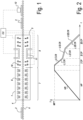
- Figure 3a illustrates a concave tile 3 that shows a concavity directed upward
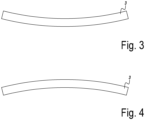
- Figure 3b illustrates a convex tile 3 that shows a concavity directed upward.
- the control unit CU commands the first or second cooling means 10, 11 to increase the upper first cooling rate UICP and/or the upper second cooling rate UIICP.
- the CPU commands the first cooling means 10 to increase the flow rate of fresh air directed towards the upper surface of the fired tile 2 in the first cooling part ICP of the cycle.
- the upper first cooling rate is increased in an adjustment area AA of the firing cycle where the adjustment of the cooling rate is more effective for correcting the planarity deviation, said adjustment area AA being close to the first end temperature, preferably between 50°C more and 50°C less than the glass transition temperature TG of the glassy phase of the ceramic tile 3.
- the control unit CU commands the first or second cooling means 10, 11 to increase the lower first cooling rate LICR and/or the lower second cooling rate LIICR.
- the CPU commands the first cooling means 10 to increase the flow rate of fresh air directed towards the lower surface of the green tile 2 in the first cooling part ICP of the cycle.
- the lower first cooling rate LICR is increased in an adjustment area AA of the firing cycle where the adjustment of the cooling rate is more effective for correcting the planarity deviation, said adjustment area AA being close to the first end temperature, between 50°C more and 50°C less than the glass transition temperature TG of the glassy phase of the ceramic tile 3.
- the method of the invention can also comprise the step of manufacturing a sample od mixture of raw material for forming the green tile 2 and measuring the glass transition temperature TG of the glassy phase formed by said mixture. Said sample can be manufactured and tested in a laboratory.
- the method subsequently, can comprise storing the measured value of glass transition temperature TG in a memory unit of said control unit CU, so that the control unit CU can adjust the cooling rate on the basis of said glass transition temperature TG and of said measured planarity deviation PD.
Landscapes
- Engineering & Computer Science (AREA)
- Chemical & Material Sciences (AREA)
- Ceramic Engineering (AREA)
- Mechanical Engineering (AREA)
- Structural Engineering (AREA)
- General Engineering & Computer Science (AREA)
- Dispersion Chemistry (AREA)
- Materials Engineering (AREA)
- Organic Chemistry (AREA)
- Manufacturing & Machinery (AREA)
- Physics & Mathematics (AREA)
- General Physics & Mathematics (AREA)
- Tunnel Furnaces (AREA)
- Finishing Walls (AREA)
- Compositions Of Oxide Ceramics (AREA)
- Press-Shaping Or Shaping Using Conveyers (AREA)
Description
- A method for manufacturing a ceramic tile and an equipment for manufacturing a ceramic tile.
- The present invention relates to a method for manufacturing a ceramic tile, in particular a floor, wall, ceiling or furniture tile, and to an equipment for manufacturing a floor tile. Ceramic tiles are manufactured via firing at high temperature, in continuous roller kiln, of a green tile comprising ceramic raw materials in form of compacted powders. During firing said powders are sintered to consolidate the ceramic material and reduce the residual porosity thereof. The high degree of sintering, especially in low porous materials like porcelain, causes a relevant shrinkage of the tile that, if not well balanced, can lead to dimensional and/or shape deformations in the final product.
- Usually, in private practice, said deformations are corrected by intervening on one or more process parameters, not necessarily belonging to the firing process, like for example pressing conditions of the powders, firing temperatures, change of materials etc. Said correction are always done manually and are based on the experience of the operator so that they are approximated and can become effective only after several trials and after the production of scraps and/or of second choice material.
- Moreover, the measurement of said deformation is made only on selected samples and, since the tiles are hot at the exit of the kiln, is often delayed to the moment when the operator can handle the sample for the measurement, so that the resulting measured deformation doesn't precisely reflect the real deformation of the product.
-
WO 2007/085317 A1 discloses a method for manufacturing ceramic tiles in accordance with the preamble of claim 1 and a corresponding system. - The present invention aims in the first place to provide an alternative method for manufacturing ceramic tile, which, in accordance with several of its preferred embodiments, is directed to solve one or more of the problems arising in the state of the art.
- Thereto, the present invention, according to its first independent aspect, relates to a method for manufacturing ceramic tiles that comprises the steps of providing a green tile formed by a mixture of ceramic raw materials, firing said green tile in a kiln to obtain a ceramic tile, said kiln being configured to fire the green tile according to a firing cycle defined by one or more firing parameter. The method of the invention has the characteristic that it comprises the steps of measuring a shape and/or dimension parameter of the obtained ceramic tile, and the step of adjusting the firing parameter on the basis of said measurement, in accordance with the wording of claim 1. Thanks to said adjustment, the efficacy of the manufacturing process can be improved.
- Preferably, while one parameter is adjustable, the remaining parameters can be kept constant (are not adjusted). In this way, it is possible to minimize interaction of multiple parameters and the adjustment is more effective.
- Said firing parameters can further comprise maximum temperature, heating rate, firing time. The inventor has found that, by acting on the cooling rate of the firing process, it is possible to improve the efficacy of the correction since the risk influence of further factors is minimized.
- It is noted that, in the most preferred embodiment, said firing cycle comprise an upper firing cycle, acting on an upper surface of the tile, and a lower firing cycle, acting on a lower surface of the tile. Said upper and lower firing cycles are defined by respective upper and lower firing parameters. Said upper and lower firing cycle can be identical or differ each other in one or more firing parameters. Preferably, said adjustable firing parameters can be both or only one of the upper and lower correspondent firing parameters, for example upper and lower cooling rate.
- It is also noted that the firing cycle comprises a heating stage and a cooling stage. Said cooling stage comprises one or more parts, preferably two, even more preferably three cooling parts. In particular, the first cooling part starts from the maximum temperature of the firing cycle, for example above 900°C, preferably between 900°C and 1250°C, and ends at a temperature around 800°C, for example between 750°C and 850°C. In case the final ceramic tile comprises a glassy phase, as it will also be explained below, said first cooling part can preferably end at a temperature preferably slightly below, the glass transition temperature of said glassy phase. For example, said first cooling part can end at a temperature being 50°C more or 50°C less than said glass transition temperature. The second cooling part starts from the end of the first cooling part and ends at a temperature around 570°C, in particular said end temperature of the second period substantially corresponds to the transition temperature between β-quartz and α-quartz. The third cooling part starts from the end of the second cooling part and ends at the exit of the kiln, for example at a temperature around 150°C. Each of the first, second and third cooling part comprises a respective first, second and third cooling rate. Preferably, each cooling part comprises a respective upper and lower cooling rate, just by way of example the first cooling part comprises an upper and a lower first cooling rate. It is noted that the second cooling part shows a cooling rate that is generally lower than in the first and second cooling part. This due to the fact that an uncomplete transformation of the quartz from β-quartz to α-quartz could lead to fractures in the tile. Preferably, according to some embodiments of the invention, the cooling rate is adjusted in the first and/or in the second cooling rate for correcting said deformation.
- Preferably, said cooling can be either direct or indirect. In case of direct cooling cool air (air at a lower temperature of the tile) can be blown directly on the upper and lower surface of the tile; in case of indirect cooling said fresh air is blown in tubes disposed below and above the tile, in such a way that the cooling is slower than in the direct cooling. Preferably, cooling is direct in the first and/or second cooling part. Preferably, cooling is indirect in the third cooling part. Preferably said cooling rate is adjusted by varying the flow condition, for example flow rate, temperature, speed, of the fresh air, either in the indirect or direct cooling.
- The shape and/or dimension parameter are measured by a measuring device connected to a control unit. Said control unit is connected to the kiln for adjusting said firing parameter. In this way the firing parameters can be adjusted immediately after said measurement so that production of scrap of second choice material can be minimized. Moreover, said adjustment can be based on a plurality of shape and/or dimension parameter measured on a same tile or on multiple tiles so that said measurement and the consequent adjustment is more accurate. Preferably said measuring device comprises optical sensor. The inventor has found that by using optical sensor the measuring can be quicker and also more accurate that by using contact sensor. In this way the measurement can be performed immediately after the exit of the kiln so that production of scrap or second choice material limited to the material in the cooling part of the kiln. In some embodiments, said deformation can be measured immediately at the exit of the kiln. In alternative embodiments, said deformation can be measured after a predetermined time after the exit of the tile from the kiln, said predetermined time preferably being at least 10min, for example at least 20min. For example, said deformation can be measured when the temperature of the tile is below a predetermined threshold temperature, said threshold temperature preferably 150°C, for example below 100°C. In this way, it may be possible to prevent influence of the temperature of the tile on the optical measuring, moreover after said predetermined time, the tile is stabilized, and the deformation becomes definitive.
- In the preferred embodiment, the measuring device comprises a device configured to measure the planarity deviation of the tile. The planarity deviation is the deviation, with respect to the flat surface, of the center of the tile. In practice, a non-planar tile can be either concave or convex; if it's concave, the tile shows an upward concavity and the center of the tile stays on a lower plane than the corners; if it's convex, the tile shows a downward concavity, and the center of the tile stays on an upper plane than the corners. The inventor, during private research has found that the planarity deviation can be caused by several factors of the whole manufacturing process of the tile including, for example, pressing condition, firing conditions, both during heating or cooling, composition of the green tile.
- During private research the inventor has found that said planarity deviation can be corrected by adjusting the cooling rate, in particular by acting on the upper and/or lower cooling rate. More in detail, the inventor has found that in case the measured planarity deviation shows a concave tile, said deviation can be corrected by increasing the upper cooling rate. The inventor has also found that in case the measured planarity deviation shows a convex tile, said deviation can be corrected by increasing the lower cooling rate. During said private research, the inventor has found that the cooling rate influences the final volume of the tile. To a higher cooling rate, corresponds a higher volume. Therefore, if the tile tends to be concave, by increasing the cooling the upper cooling rate, the volume of the upper part of the tile will be higher than the lower one so that the deformation that causes the concavity can be compensated. It is noted that by acting on the upper and/or cooling rate it may be possible to correct planarity deviations caused by upstream factors of the process like, for example, pressing condition without intervening on said upstream factors themselves. Therefore, the correction of the planarity can be performed in an easy way without the need of intervening on multiple factors that could cause other deformation.
- During internal observation the inventor has found that the tiles obtained in standard processes have the tendency to be convex rather than concave. The inventor has observed that said planarity deformation can be due to the fact that cooling can be more efficient, and thus the cooling rate higher, on the upper surface of the tile. This may be due to a sort of thermal shield effect caused by the presence of the roller and by the difficulty of blowing fresh air upward in a hot environment. Therefore, in the most preferred embodiment, said adjustment of the cooling rate is performed especially, or even exclusively, on the upper cooling rate. This preferred embodiment a convex planarity deviation can be adjusted by lowering down the upper cooling rate. On the other hand, a concave planarity deviation can be adjusted by increasing the upper cooling rate.
- Preferably the tile comprises a support made of a ceramic material, for example porcelain, red body tile, earthenware, single fire wall tile. The tile can further comprise a top layer comprising one or more glaze layers. In the most preferred embodiment, the support is made of porcelain and preferably comprises one or more glaze layers on the upper surface.
- In the preferred embodiment the support layer, of the fired tile, can comprise a glassy phase. Preferably said glassy phase is at least partially formed during the firing process.
- Said glassy phase can represent up to the 80%, for example between 50 and 75% based on the total weight of the support. The inventor has found that it is particularly the glassy phase of the ceramic tile that shows the tendency to vary the volume according to the cooling rate, thereto in presence of a high quantity of glassy phase the adjustment of the cooling rate is more effective in contrasting the planarity deviation for ceramic material having a higher content of glassy phase. To this aim the effect of the cooling rate adjustment is particularly effective in case of tiles having one more glaze layer on the upper surface since said glazes are mostly or completely made of vitreous material.
- The inventor has also found that the adjustment of the cooling temperature becomes particularly effective in contrasting the planarity deviation when the cooling rate is modified around the glass transition temperature of the glassy phase. Said firing parameter is adjusted on the basis of said measurement and on the basis of said glass transition temperature. In accordance with the invention said cooling rate is adjusted when the temperature of the tile is in a range between 50°C more and 50°C less than the glass transition temperature of the glassy phase, for example between 750°C and 850°C. In fact, the inventor has surprisingly found that final volume of the tile changes when the cooling rate is changed in proximity of the glass transition temperature of the glassy phase. To this aim the cooling rate can be adjusted across the transition between the first and the second cooling part of the firing cycle. Preferably the cooling rate can be adjusted only in a limited portion of the first and/or of the second cooling part of the firing cycle.
- The method may conveniently comprise the step of determining the glass transition temperature of the mixture of raw materials of the green tile, i.e. of the glassy phase of the tile, and/or of any glaze layers and adjusting said firing parameter on the basis of said determined values. In some embodiment, said determined value can be stored in a memory connected to the control unit, for example a personal computer, for controlling the kiln.
- The kiln can comprise multiple temperature sensors, for example thermocouple, for measuring the temperature in the kiln in multiple points or sector of the kiln, so to that the temperature of the tile during its advancement in the kiln can be monitored. Preferably, said temperature sensors can be connected to the control unit that controls the kiln so that the adjustment of the cooling rate can be commanded only where it can be most effective, for example where the temperature is in proximity of the glass transition temperature of the glassy phase. In this way, for example only certain cooling means of the kiln can be controlled, i.e. those located in the portion of the kiln where the temperature is close the glass transition temperature of the kiln.
- A second independent aspect of the invention relates to a system for carrying on the method of the first aspect. In particular, said second aspect provides for a system for manufacturing ceramic tiles comprising: a kiln configured for fire green ceramic tile according to a firing cycle defined by one or more firing parameters to obtain a ceramic tile, said kiln comprising one or more means for controlling said firing parameters; a device for measuring a shape and/or dimension parameter of the ceramic tile; a control unit connected to the device and to the kiln and configure to control said means on the basis of the measured value.
- Said kiln preferably is a continuous kiln having a inlet opening and an exit opening. Said kiln can be a roller kiln. Rollers have the advantage that the tiles run on the rollers in form of one layer so that heat exchange at the upper and lower surface of the tile is optimized.
- Said devices for controlling the parameters can comprise burners, blowers for hot hair, fresh air flow valves, engine for rotating the rollers etc.
- Said device for measuring the shape and/or dimension parameter can comprise optical sensor. For example, said device is a device configured to measure a planarity deviation of the ceramic tile. Said device can be for example a laser gauges for applications on industrial processing lines.
- With the intention of better showing the characteristics of the invention, in the following, as an example without any limitative character, several preferred forms of embodiments are described with reference to the accompanying drawings, wherein:
-
Figure 1 schematically shows some step of a method according to the invention, and a system for carrying on the invention; -
Figure 2 shows a firing cycle for ceramic tile according to the invention; - Figure 3a and 3b show a schematic side view respectively of a concave and of a convex tile.
-
Figure 1 shows a roller kiln 1 for firing agreen tile 2 to obtain aceramic tile 3. The kiln 1 has an inlet opening 4 and an exit opening 5. - The
green tile 2 has an upper and a lower surface. The green tile comprising at least a support made of a mixture of ceramic raw materials like, for example clays, kaolin, feldspar, calcium carbonate, zirconium silicate, talc, quartz and frits. The ceramic mixture forming the support of the green tile is configured for forming a glassy phase in the support of theceramic tile 3. In the example said mixture is a mixture for porcelain tiles or slabs for floor, wall or furniture, and is configured for forming a glassy phase of for example between 50 and 70% based on the total weight of the support. Thegreen tile 2, and consequently theceramic tile 3, can comprise one or more glaze layers covering the upper surface of the support. It is noted that within the context of the present invention withceramic tile 3 it is meant a ceramic tile after completion of the firing process in the kiln 1 and thus the expression ceramic tile it is used to refer to a tile after the exit from the kiln 1, whereas the expression green tile is used before and inside the kiln 1. - The kiln 1 comprises a plurality of
motorized rollers 6 for advancing thegreen tile 2 from the inlet opening 4 toward the exit opening 5, the rollers supporting the lower surface of thegreen tile 2. - The kiln 1 comprises a
heating portion 7 closer to the inlet opening 4 provided withburners 8 disposed above and below said rollers. Downstream to saidheating portion 7, the kiln 1 is provided with a coolingportion 9 until the exit opening 5. Said coolingportion 9 is provided by first cooling means 10, for example air blowers or fans connected to tubes provided with ejecting nozzles or orifices, for direct cooling of the firedtile 2. In particular, the first cooling means are adapted to blow or convey a flow of air directly in contact with the tile. Preferably, said first cooling means 10 are disposed above and/or below saidrollers 6 in such a way to blow fresh air on the upper and lower surface of the tile respectively. Said coolingpart 9 is also provided by second cooling means 11 for indirect cooling of thegreen tile 2. In particular, the second cooling means comprise closed tubes for the flow of fresh air in the cooling portion for receiving heat from the tile. Preferably, said second cooling means 11 are disposed above and/or below saidrollers 6. It is noted that within the context of the present invention with "fresh air" it is meant air that is colder than the tile, and that it can be used to cool the tile. -
Figure 1 further shows adevice 12 configured to measure a shape and/or dimension parameter of thetile 3. Thedevice 12 is disposed downstream the exit 5 of the kiln 1. In the preferred embodiment saiddevice 12 comprises an optical sensor adapted to determine a planarity deviation of theceramic tile 3. For example, thedevice 12 is laser gauges for applications on industrial processing lines. - The
device 12 is connected to a control unit CU, for example a computer, that is connected to the first and/or the second cooling means 10, 11 for controlling them. -
Figure 2 schematically a possible firing cycle for firingceramic tiles 3 using the kiln 1 shown infigure 1 . In particular,figure 2 shows two firing cycles slightly different each other and active respectively on the upper surface and on the lower surface of the firedtile 2. -
Figure 2 shows that the firing cycle comprises a heating part HP wherein the temperature T of thegreen tile 2 increases with a substantially constant heating rate HR up to a maximum firing temperature MFT. Said heating rate being for example comprised between 80 and 150°C/min.Figure 2 shows that heating rate can be slightly different on the upper surface of the tile and on the lower surface and that the heating part comprises an upper heating rate UHR and a lower heating rate LHR. -
Figure 2 shows that the maximum firing temperature can be maintained substantially constant for a predetermined interval. The maximum firing temperature MFT is preferably above 1000°C, for example for porcelain tiles, being between 1200°C and 1270°C. -
Figure 2 shows that the firing cycle comprises a first cooling part ICP where the temperature T of the firedtile 2 decreases with a substantially constant first cooling rate ICR from the maximum firing temperature MFT down to a first end temperature, preferably between 750°C and 850°C, said first end temperature being preferably in a range of between 50°C more and 50°C less than the glass transition temperature TG of the glassy phase of theceramic tile 3. Said first cooling rate being for example comprised between 120 and 150 °C/min.Figure 2 shows that first cooling rate can be slightly different on the upper surface of the tile and on the lower surface and that the first cooling part comprises an upper first cooling rate UICR and a lower first heating rate LICR. Preferably during said first cooling part ICP the firedtile 2 is cooled via the direct cooling through the first cooling means 10. -
Figure 2 shows that the firing cycle comprises a second cooling part IICP where the temperature T of the firedtile 2 decreases with a substantially constant second cooling rate IICR from the first end temperature down to a second end temperature, preferably below 570 °C. Said second cooling rate is lower than the first cooling rate, for example is between 100 and 80 °C/min.Figure 2 shows that second cooling rate can be slightly different on the upper surface of the tile and on the lower surface and that the second cooling part comprises an upper second cooling rate UIICR and a lower second heating rate LIICR. Preferably during said second cooling part IICP the firedtile 2 is cooled via the indirect cooling through the second cooling means 11. -
Figure 2 shows that the firing cycle comprises a third cooling part IIICP where the temperature T of the firedtile 2 decreases with a substantially constant third cooling rate IIICR from the second end temperature down to a final temperature, preferably around 100 °C. Said third cooling rate is higher than the second cooling rate, for example is between 120 and 150 °C/min.Figure 2 shows that third cooling rate can be slightly different on the upper surface of the tile and on the lower surface and that the second cooling part comprises an upper third cooling rate UIIICR and a lower third heating rate LIIICR. Preferably during said third cooling part IIICP the firedtile 2 is cooled via the direct cooling through the first cooling means 10. - Figure 3a illustrates a
concave tile 3 that shows a concavity directed upward; Figure 3b illustrates aconvex tile 3 that shows a concavity directed upward. - When the
device 12 measures a planarity deviation PD corresponding to aconcave tile 3, as shown in figure 3a, the control unit CU commands the first or second cooling means 10, 11 to increase the upper first cooling rate UICP and/or the upper second cooling rate UIICP. In the preferred embodiment, for example, the CPU commands the first cooling means 10 to increase the flow rate of fresh air directed towards the upper surface of the firedtile 2 in the first cooling part ICP of the cycle. Preferably the upper first cooling rate is increased in an adjustment area AA of the firing cycle where the adjustment of the cooling rate is more effective for correcting the planarity deviation, said adjustment area AA being close to the first end temperature, preferably between 50°C more and 50°C less than the glass transition temperature TG of the glassy phase of theceramic tile 3. - When the
device 12 measures a planarity deviation PD corresponding to aconvex tile 3, as shown in figure 3b, the control unit CU commands the first or second cooling means 10, 11 to increase the lower first cooling rate LICR and/or the lower second cooling rate LIICR. In the preferred embodiment, for example, the CPU commands the first cooling means 10 to increase the flow rate of fresh air directed towards the lower surface of thegreen tile 2 in the first cooling part ICP of the cycle. Preferably the lower first cooling rate LICR is increased in an adjustment area AA of the firing cycle where the adjustment of the cooling rate is more effective for correcting the planarity deviation, said adjustment area AA being close to the first end temperature, between 50°C more and 50°C less than the glass transition temperature TG of the glassy phase of theceramic tile 3. - The method of the invention can also comprise the step of manufacturing a sample od mixture of raw material for forming the
green tile 2 and measuring the glass transition temperature TG of the glassy phase formed by said mixture. Said sample can be manufactured and tested in a laboratory. The method subsequently, can comprise storing the measured value of glass transition temperature TG in a memory unit of said control unit CU, so that the control unit CU can adjust the cooling rate on the basis of said glass transition temperature TG and of said measured planarity deviation PD. - The present invention is in no way limited to the hereinabove described embodiments, but such equipment and/or plant may be realized according to different variants without leaving the scope of the present invention.
Claims (14)
- A method for manufacturing ceramic tiles (3) that comprises the steps of providing a green tile (2) formed by a mixture of ceramic raw materials, firing said green tile (2) in a kiln (1) to obtain a ceramic tile (3), said kiln (1) being configured to fire the green tile (2) according to a firing cycle defined by one or more firing parameter (HR, MFT, UICR, UIICR, UIIICR, LICR, LIICR, LIIICR), wherein it comprises the steps of measuring a shape and/or dimension parameter of the obtained ceramic tile (3), characterized by the step of adjusting a cooling rate (UICR, UIICR, UIIICR, LICR, LIICR, LIIICR) in the kiln (1) between 50°C above or 50°C below the glass transition temperature of a glassy phase of the tile (3) on the basis of said measurement, preferably while one parameter is adjustable the remaining parameters are to be kept constant.
- The method according to claim 1, characterized in that said firing parameters can comprise maximum temperature, heating rate, cooling rate, firing time.
- The method according to claim 1 or 2, characterized in that said firing cycle comprises an upper firing cycle, acting on an upper surface of the tile, and a lower firing cycle, having respective upper and lower firing parameter (UICR, UIICR, UIIICR, LICR, LIICR, LIIICR), wherein said adjustable firing parameters comprise at least one of the upper and lower correspondent firing parameters, preferably upper cooling rate (UICR, UIICR, UIIICR) and lower cooling rate (LICR, LIICR, LIIICR).
- The method according to any of the preceding claims, characterized in that the firing cycle comprises:- a first cooling part (ICP), preferably starting from the maximum temperature (MFT) of the firing cycle, and ending at a temperature around 800°C, for example between 750°C and 850°C, or ending at a temperature being 50°C more or 50°C less than a glass transition temperature of the ceramic tile, or of a glassy phase thereof, said first cooling part having a respective first cooling rate (UICR, LICR); and/or- a second cooling part (IICP) that starts from the end of the first cooling part (ICP) and ends at a temperature around 570°C, said second cooling part having a second cooling rate (UIICR, LIICR); and/or- a third cooling part (IICP) starting from the end of the second cooling part (IICP) and ending at the exit of the kiln (1), said third cooling part having a third cooling rate (UIICR, LIIICR).
- The method according to any of the preceding claims, characterized in that said kiln (1) is adapted to cool the tile via indirect cooling and/or via direct cooling, and wherein the method comprises adjusting the cooling rate in said direct cooling.
- The method according to any of the preceding claims, characterized in that the shape and/or dimension parameter can be preferably measured by a measuring device (12) connected to a control unit (CU), preferably said control unit being connected to the kiln (1) for adjusting said firing parameter.
- The method according to claim 6, characterized in that said measuring device (12) comprises optical sensor.
- The method according to any of the preceding claims, characterized in that said steps of measuring a shape and/or dimension parameter of the obtained ceramic tile (3) is measured:- immediately at the exit of the kiln (1); or- after a predetermined time after the exit of the tile (3) from the kiln (1), said predetermined time preferably being at least 10min, for example at least 20min; and/or- when the temperature of the tile (3) is below a predetermined threshold temperature, preferably said threshold temperature being 150°C or below, for example below 100°C.
- The method according to any of the preceding claims, characterized in that said steps of measuring a shape and/or dimension parameter of the obtained ceramic tile (3) comprises the planarity deviation of the tile.
- The method according to claims 9 and 3, characterized in that in case the measured planarity deviation shows a convex tile (3), said deviation can be corrected by increasing a lower cooling rate (LICR, LIICR) or decreasing a upper cooling rate(UICR, UIICR); and/or in case in case the measured planarity deviation shows a concave tile, said deviation can be corrected by decreasing a lower cooling rate (LICR, LIICR) or increasing a upper cooling rate (UICR, UIICR).
- The method according to any of the preceding claims, characterized in that the tile (3) comprises a top layer comprising one or more glaze layers.
- The method according to any of the preceding claims, characterized in that the obtained fired tile (3) comprises a support having a glassy phase, preferably wherein said glassy phase represents up to the 80%, for example between 50 and 75% based on the total weight of the support.
- The method according to any of the preceding claims, characterized in that it comprises the step of determining the glass transition temperature of the mixture of raw materials of the green tile, i.e. of the glassy phase of the tile, and/or of any glaze layers and adjusting said firing parameter on the basis of said determined values.
- A system for manufacturing ceramic tiles (3), comprising:- a kiln (1) configured for fire green ceramic tile (2) according to a firing cycle defined by one or more firing parameters (HR, MFT, UICR, UIICR, UIIICR, LICR, LIICR, LIIICR) to obtain a ceramic tile (3), said kiln (1) comprising one or more devices (8, 10, 11) for controlling said firing parameters (HR, MFT, UICR, UIICR, UIIICR, LICR, LIICR, LIIICR);- a device (12) for measuring a shape and/or dimension parameter of the ceramic tile (3);- a control unit (C) connected to the measuring device (12) and to the kiln (1) and configured to control said devices (9,10,11) of the kiln (1) on the basis of the measured value, in accordance with the method as per the preceding claim 1.
Priority Applications (6)
| Application Number | Priority Date | Filing Date | Title |
|---|---|---|---|
| PL22160582.7T PL4241951T3 (en) | 2022-03-07 | 2022-03-07 | A method for manufacturing a ceramic tile and an equipment for manufacturing a ceramic tile |
| ES22160582T ES3034542T3 (en) | 2022-03-07 | 2022-03-07 | A method for manufacturing a ceramic tile and an equipment for manufacturing a ceramic tile |
| EP22160582.7A EP4241951B1 (en) | 2022-03-07 | 2022-03-07 | A method for manufacturing a ceramic tile and an equipment for manufacturing a ceramic tile |
| EP23710100.1A EP4489953A1 (en) | 2022-03-07 | 2023-03-03 | A method for manufacturing a ceramic tile and an equipment for manufacturing a ceramic tile |
| PCT/IB2023/051990 WO2023170527A1 (en) | 2022-03-07 | 2023-03-03 | A method for manufacturing a ceramic tile and an equipment for manufacturing a ceramic tile. |
| US18/844,174 US20250171362A1 (en) | 2022-03-07 | 2023-03-03 | A method for manufacturing a ceramic tile and an equipment for manufacturing a ceramic tile. |
Applications Claiming Priority (1)
| Application Number | Priority Date | Filing Date | Title |
|---|---|---|---|
| EP22160582.7A EP4241951B1 (en) | 2022-03-07 | 2022-03-07 | A method for manufacturing a ceramic tile and an equipment for manufacturing a ceramic tile |
Publications (2)
| Publication Number | Publication Date |
|---|---|
| EP4241951A1 EP4241951A1 (en) | 2023-09-13 |
| EP4241951B1 true EP4241951B1 (en) | 2025-05-07 |
Family
ID=80978840
Family Applications (2)
| Application Number | Title | Priority Date | Filing Date |
|---|---|---|---|
| EP22160582.7A Active EP4241951B1 (en) | 2022-03-07 | 2022-03-07 | A method for manufacturing a ceramic tile and an equipment for manufacturing a ceramic tile |
| EP23710100.1A Pending EP4489953A1 (en) | 2022-03-07 | 2023-03-03 | A method for manufacturing a ceramic tile and an equipment for manufacturing a ceramic tile |
Family Applications After (1)
| Application Number | Title | Priority Date | Filing Date |
|---|---|---|---|
| EP23710100.1A Pending EP4489953A1 (en) | 2022-03-07 | 2023-03-03 | A method for manufacturing a ceramic tile and an equipment for manufacturing a ceramic tile |
Country Status (5)
| Country | Link |
|---|---|
| US (1) | US20250171362A1 (en) |
| EP (2) | EP4241951B1 (en) |
| ES (1) | ES3034542T3 (en) |
| PL (1) | PL4241951T3 (en) |
| WO (1) | WO2023170527A1 (en) |
Families Citing this family (3)
| Publication number | Priority date | Publication date | Assignee | Title |
|---|---|---|---|---|
| WO2025238534A1 (en) | 2024-05-14 | 2025-11-20 | Sacmi Cooperativa Meccanici Imola Societa' Cooperativa | Line and method for the production of decorated ceramic products in a continuous cycle |
| WO2025238536A1 (en) | 2024-05-14 | 2025-11-20 | Sacmi Cooperativa Meccanici Imola Societa' Cooperativa | Method for creating a database for a continuous cycle production line for decorated ceramic products and computer server containing the database |
| WO2026018122A1 (en) | 2024-07-18 | 2026-01-22 | Marazzi Group Srl A Socio Unico | Method for tracking products in a ceramic tiles manufacturing process |
Citations (13)
| Publication number | Priority date | Publication date | Assignee | Title |
|---|---|---|---|---|
| SU426126A1 (en) | 1972-10-16 | 1974-04-30 | институт автоматизации предпри тий промышленности строительных | |
| US4462797A (en) | 1982-04-21 | 1984-07-31 | Gottfried Cremer | Cooling zone for a kiln, more specially a roller kiln |
| US4834646A (en) | 1986-03-22 | 1989-05-30 | Ngk Insulators, Ltd. | Process for cooling fired products in a kiln |
| US5830251A (en) | 1996-04-10 | 1998-11-03 | Vortec Corporation | Manufacture of ceramic tiles from industrial waste |
| US5900202A (en) | 1997-09-26 | 1999-05-04 | Lingart; Youri | Method for making glass silicate tiles |
| ITRE20000096A1 (en) | 2000-10-16 | 2002-04-16 | Sacmi Forni Spa | COOKING OVEN FOR CERAMIC TILES WITH PERFECTED COOLING SECTION |
| EP1500889A1 (en) | 2003-07-25 | 2005-01-26 | Tck S.R.L. | Monitoring system of a ceramics kiln |
| WO2007085317A1 (en) | 2006-01-26 | 2007-08-02 | Sacmi Forni S.P.A. | A process and an apparatus for optimised management of a kiln for ceramic tiles |
| EP1884730A2 (en) | 2006-07-28 | 2008-02-06 | Sacmi forni S.p.A. | A tunnel kiln for ceramic products |
| ITRE20120058A1 (en) | 2012-09-21 | 2014-03-22 | Sacmi Forni Spa | OVEN FOR CONTINUOUS COOKING OF BRICKS ON CASSETTE SUPPORTS |
| WO2015015263A2 (en) | 2013-08-02 | 2015-02-05 | Sacmi Cooperativa Meccanici Imola Societá Cooperativa | A radiating heating module for continuous-cycle firing kilns of ceramic products |
| IT201600131763A1 (en) | 2016-12-28 | 2018-06-28 | Sacmi Forni Spa | OVEN FOR COOKING CERAMIC ARTICLES |
| IT201600131761A1 (en) | 2016-12-28 | 2018-06-28 | Sacmi Forni Spa | OVEN FOR COOKING CERAMIC ARTICLES |
-
2022
- 2022-03-07 EP EP22160582.7A patent/EP4241951B1/en active Active
- 2022-03-07 PL PL22160582.7T patent/PL4241951T3/en unknown
- 2022-03-07 ES ES22160582T patent/ES3034542T3/en active Active
-
2023
- 2023-03-03 EP EP23710100.1A patent/EP4489953A1/en active Pending
- 2023-03-03 WO PCT/IB2023/051990 patent/WO2023170527A1/en not_active Ceased
- 2023-03-03 US US18/844,174 patent/US20250171362A1/en active Pending
Patent Citations (13)
| Publication number | Priority date | Publication date | Assignee | Title |
|---|---|---|---|---|
| SU426126A1 (en) | 1972-10-16 | 1974-04-30 | институт автоматизации предпри тий промышленности строительных | |
| US4462797A (en) | 1982-04-21 | 1984-07-31 | Gottfried Cremer | Cooling zone for a kiln, more specially a roller kiln |
| US4834646A (en) | 1986-03-22 | 1989-05-30 | Ngk Insulators, Ltd. | Process for cooling fired products in a kiln |
| US5830251A (en) | 1996-04-10 | 1998-11-03 | Vortec Corporation | Manufacture of ceramic tiles from industrial waste |
| US5900202A (en) | 1997-09-26 | 1999-05-04 | Lingart; Youri | Method for making glass silicate tiles |
| ITRE20000096A1 (en) | 2000-10-16 | 2002-04-16 | Sacmi Forni Spa | COOKING OVEN FOR CERAMIC TILES WITH PERFECTED COOLING SECTION |
| EP1500889A1 (en) | 2003-07-25 | 2005-01-26 | Tck S.R.L. | Monitoring system of a ceramics kiln |
| WO2007085317A1 (en) | 2006-01-26 | 2007-08-02 | Sacmi Forni S.P.A. | A process and an apparatus for optimised management of a kiln for ceramic tiles |
| EP1884730A2 (en) | 2006-07-28 | 2008-02-06 | Sacmi forni S.p.A. | A tunnel kiln for ceramic products |
| ITRE20120058A1 (en) | 2012-09-21 | 2014-03-22 | Sacmi Forni Spa | OVEN FOR CONTINUOUS COOKING OF BRICKS ON CASSETTE SUPPORTS |
| WO2015015263A2 (en) | 2013-08-02 | 2015-02-05 | Sacmi Cooperativa Meccanici Imola Societá Cooperativa | A radiating heating module for continuous-cycle firing kilns of ceramic products |
| IT201600131763A1 (en) | 2016-12-28 | 2018-06-28 | Sacmi Forni Spa | OVEN FOR COOKING CERAMIC ARTICLES |
| IT201600131761A1 (en) | 2016-12-28 | 2018-06-28 | Sacmi Forni Spa | OVEN FOR COOKING CERAMIC ARTICLES |
Non-Patent Citations (20)
| Title |
|---|
| ANONYMOUS: "A comparison of the glass transition measured by DSC, TMA and DMA", METTLER-TOLDEO AG, 1 December 2009 (2009-12-01), XP093369092 |
| ANONYMOUS: "Measurement of the glass transition temperature TG", GLASS PROPERTIES, 5 November 2007 (2007-11-05), XP093369087, Retrieved from the Internet <URL:https://glassproperties.com/tg/> |
| ARNDT J., HÄBERLE F.: "Thermal expansion and glass transition temperatures of synthetic glasses of plagioclase-like compositions", CONTRIBUTIONS TO MINERALOGY AND PETROLOGY, SPRINGER BERLIN HEIDELBERG, BERLIN/HEIDELBERG, vol. 39, no. 2, 1 January 1973 (1973-01-01), Berlin/Heidelberg , pages 175 - 183, XP093369077, ISSN: 0010-7999, DOI: 10.1007/BF00375739 |
| C. ZANELLI; M. RAIMONDO; G. GUARINI; M. DONDI;: "The vitreous phase of porcelain stoneware: Composition, evolution during sintering and physical properties", JOURNAL OF NON-CRYSTALLINE SOLIDS, NORTH-HOLLAND PHYSICS PUBLISHING. AMSTERDAM., NL, vol. 357, no. 16, NL , pages 3251 - 3260, XP028231576, ISSN: 0022-3093, DOI: 10.1016/j.jnoncrysol.2011.05.020 |
| CANTAVELLA V, GARCÍA-TEN J, SÁNCHEZ E, BANNIER E, SÁNCHEZ J, SOLER C, SALES J, CASTELLÓN JAUME I, SPAIN, TAULELL ), TAU S A, CASTE: "DELAYED CURVATURES IN PORCELAIN TILE. ANALYSIS AND MEASUREMENT OF INFLUENCING FACTORS", QUALICER, 2008, 1 January 2008 (2008-01-01), XP093369069, Retrieved from the Internet <URL:https://www.qualicer.org/recopilatorio/ponencias/pdfs/0823173e.pdf> |
| CONTE SONIA, ZANELLI CHIARA, ARDIT MATTEO, CRUCIANI GIUSEPPE, DONDI MICHELE: "Predicting Viscosity and Surface Tension at High Temperature of Porcelain Stoneware Bodies: A Methodological Approach", MATERIALS, MDPI AG, vol. 11, no. 12, pages 2475, XP093369074, ISSN: 1996-1944, DOI: 10.3390/ma11122475 |
| D13 - DILATOMETRIC AGREEMENT IN DOUBLE COMPACTION PORCELAIN TILE |
| D14 - INFLUENCE OF COMPOSITION ON MECHANICAL BEHAVIOUR OF PORCELAIN TILE. |
| D16 - EXPERIMENTAL STUDY OF TYPICAL DEFECTS IN TRADITIONAL CERAMIC PRODUCTS |
| D17 - STUDIO DEI PROCESSI DI SINTERIZZAZIONE E RAFFREDDAMENTO |
| D21A - ZANNINI, PAOLO: "Applied Ceramic Technology - Volume I", 1 December 2002, SACMI, ISBN: 88-88108-48-3, article ZANNINI, PAOLO: "Chapter IV - Raw materials for frits and glazes", pages: 139 - 174, XP009565937 |
| D29 - W. OCHEN: "Influence of residual stress on the mechanical behavior of ceramics with various quartz sizes", SCIENTIFIC AFRICAN, vol. 11, December 2009 (2009-12-01) |
| DAL BÓ MARCELO, CANTAVELLA VICENTE, SÁNCHEZ ENRIQUE, HOTZA DACHAMIR, BOSCHI ANSELMO: "MECHANICAL MODELLING OF RAPID COOLING IN PORCELAIN TILE-TYPE SYSTEMS", QUALICER THE WORLD CONGRESS ON CERAMIC TILE QUALITY, 1 December 2012 (2012-12-01), XP093369066, ISBN: 978-84-95931-38-2, Retrieved from the Internet <URL:https://www.qualicer.org/recopilatorio/ponencias/pdfs/2012075.pdf> |
| DELAVI D.G.G., J. GARCÍA-TEN, A. SABURIT, A. ESCRIG, D. HOTZA: "PORCELAIN TILE BEHAVIOUR UNDER CUTTING. RELATIONSHIP WITH RESIDUAL STRESSES", QUALICER '16, 1 December 2016 (2016-12-01), XP093369073 |
| GARCÍA-TEN JAVIER, TISCAR JUAN MIGUEL: "WP2. Residual stresses in porcelain tiles - Modelling of the stresses during the cooling", TECNARGILLA, 27 September 2018 (2018-09-27), XP093369096 |
| QUEREDA M F, SABURIT A, GARCÍA TEN J, LORENTE M M, GIMENO C, SÁNCHEZ A: "USE Of ThE OPTICAL fLEXIMETER TO EVALUATE ThE TENDENCY Of CERAMIC TILES AND TILE BODIES TO DEfORM DURING fIRING", QUALICER 2012, 1 January 2012 (2012-01-01), XP093369081, Retrieved from the Internet <URL:https://www.qualicer.org/recopilatorio/ponencias/pdfs/2012121.pdf> |
| SANDITOV DAMBA S, OJOVAN MICHAEL I: "INVITED SCIENTIFIC REPORT 2 - RELAXATION ASPECTS OF THE GLASS TRANSITION", JOINT ICTP-IAEA WORKSHOP "FUNDAMENTALS OF VITRIFICATION AND VITREOUS MATERIALS FOR NUCLEAR WASTE IMMOBILIZATION"., 6 November 2017 (2017-11-06), XP093369097 |
| SANDITOV DAMBA S.; OJOVAN MICHAEL I.: "On relaxation nature of glass transition in amorphous materials", PHYSICA B: CONDENSED MATTER, ELSEVIER, AMSTERDAM, NL, vol. 523, 1 January 1900 (1900-01-01), AMSTERDAM, NL , pages 96 - 113, XP085157595, ISSN: 0921-4526, DOI: 10.1016/j.physb.2017.08.025 |
| TRACHENKO KOSTYA, BRAZHKIN V. V.: "Heat capacity at the glass transition", PHYSICAL REVIEW B, AMERICAN PHYSICAL SOCIETY, US, vol. 83, no. 1, 1 January 2011 (2011-01-01), US , XP093369075, ISSN: 1098-0121, DOI: 10.1103/PhysRevB.83.014201 |
| ZANNINI, PAOLO: "Applied Ceramic Technology - Volume II", 1 January 2002, SACMI, ISBN: 88-88108-55-6, article ZANNINI, PAOLO: "Chapter VI - Firing", pages: 207 - 242, XP009565535 |
Also Published As
| Publication number | Publication date |
|---|---|
| US20250171362A1 (en) | 2025-05-29 |
| PL4241951T3 (en) | 2025-08-18 |
| EP4241951A1 (en) | 2023-09-13 |
| EP4489953A1 (en) | 2025-01-15 |
| ES3034542T3 (en) | 2025-08-19 |
| WO2023170527A1 (en) | 2023-09-14 |
Similar Documents
| Publication | Publication Date | Title |
|---|---|---|
| US20250171362A1 (en) | A method for manufacturing a ceramic tile and an equipment for manufacturing a ceramic tile. | |
| TWI637141B (en) | Heat treatment furnace and heat treatment method | |
| KR930012000B1 (en) | Process and apparatus for producing glazed ceramic tiles, and tiles so obtained | |
| US20250178975A1 (en) | Slate hot bending furnace and method for performing hot bending treatment on slate | |
| KR101193351B1 (en) | Furnace | |
| US6511628B2 (en) | Method for controlling the firing of ceramics | |
| CN217677289U (en) | Hot processing die for curved ceramic plate | |
| CN101360966B (en) | Method and device for optimizing the management of a tile kiln | |
| CN101277799A (en) | Method of forming refractory shaped item for mounting on plate glass forming apparatus, refractory shaped item, method of forming plate glass and plate glass | |
| CN109186259A (en) | A kind of ceramic packing sintering kiln | |
| CN108395273A (en) | A kind of production technology improving foamed ceramic partition plate fire endurance | |
| CN117142757B (en) | Glass annealing tunnel kiln with controllable humidity and adjustable flatness | |
| US20100081560A1 (en) | general-purpose method for producing large-sized ceramic products such as houses or rooms from clay, large-sized blocks, bricks, and ceiling slabs (embodiments) | |
| Rimpel | POTENTIALITIES AND LIMITS OF DIRECT FLOW DRYING OF VERTICALLY PERFORATED CLAY BRICKS IN COMPARISON WITH CONVENTIONAL CONVECTION DRYING IN LARGE AREAS | |
| JP2678332B2 (en) | Method for determining firing conditions for ceramic products and electric furnace used for the method | |
| JP2010100490A (en) | Method for measuring firing temperature of fired product | |
| JP2627390B2 (en) | Control method and control device in heat treatment apparatus | |
| JP2006275330A (en) | Kiln | |
| JPH10202645A (en) | Device for continuously manufacturing ceramic plate | |
| JPH0544425B2 (en) | ||
| SU356260A1 (en) | METHOD OF SINGLE-VOLUME GRINDING OF CERAMIC PRODUCTS | |
| JPH10230510A (en) | Continuously producing apparatus of earthenware plate | |
| Herzog et al. | INFLUENCING THE PRODUCT PROPERTIES OF CLAY ROOFING TILES BY CHANGING THE MATERIAL AND PROCESS TECHNOLOGY CONDITIONS | |
| TR2022003980A2 (en) | ANORTITE CRYSTAL PHASE GLASE COMPOSITION DEVELOPED BY USING ALUMINA-BASED FIRE ZONE WASTE COILS WITHOUT CRYSTOBALITE PHASE INSTEAD OF ALUMINUM OXIDE | |
| JPH0544424B2 (en) |
Legal Events
| Date | Code | Title | Description |
|---|---|---|---|
| PUAI | Public reference made under article 153(3) epc to a published international application that has entered the european phase |
Free format text: ORIGINAL CODE: 0009012 |
|
| STAA | Information on the status of an ep patent application or granted ep patent |
Free format text: STATUS: THE APPLICATION HAS BEEN PUBLISHED |
|
| AK | Designated contracting states |
Kind code of ref document: A1 Designated state(s): AL AT BE BG CH CY CZ DE DK EE ES FI FR GB GR HR HU IE IS IT LI LT LU LV MC MK MT NL NO PL PT RO RS SE SI SK SM TR |
|
| STAA | Information on the status of an ep patent application or granted ep patent |
Free format text: STATUS: REQUEST FOR EXAMINATION WAS MADE |
|
| 17P | Request for examination filed |
Effective date: 20240226 |
|
| RBV | Designated contracting states (corrected) |
Designated state(s): AL AT BE BG CH CY CZ DE DK EE ES FI FR GB GR HR HU IE IS IT LI LT LU LV MC MK MT NL NO PL PT RO RS SE SI SK SM TR |
|
| GRAP | Despatch of communication of intention to grant a patent |
Free format text: ORIGINAL CODE: EPIDOSNIGR1 |
|
| STAA | Information on the status of an ep patent application or granted ep patent |
Free format text: STATUS: GRANT OF PATENT IS INTENDED |
|
| INTG | Intention to grant announced |
Effective date: 20241009 |
|
| GRAS | Grant fee paid |
Free format text: ORIGINAL CODE: EPIDOSNIGR3 |
|
| P01 | Opt-out of the competence of the unified patent court (upc) registered |
Free format text: CASE NUMBER: APP_4818/2025 Effective date: 20250129 |
|
| GRAA | (expected) grant |
Free format text: ORIGINAL CODE: 0009210 |
|
| STAA | Information on the status of an ep patent application or granted ep patent |
Free format text: STATUS: THE PATENT HAS BEEN GRANTED |
|
| AK | Designated contracting states |
Kind code of ref document: B1 Designated state(s): AL AT BE BG CH CY CZ DE DK EE ES FI FR GB GR HR HU IE IS IT LI LT LU LV MC MK MT NL NO PL PT RO RS SE SI SK SM TR |
|
| REG | Reference to a national code |
Ref country code: GB Ref legal event code: FG4D |
|
| REG | Reference to a national code |
Ref country code: CH Ref legal event code: EP |
|
| REG | Reference to a national code |
Ref country code: DE Ref legal event code: R096 Ref document number: 602022014085 Country of ref document: DE |
|
| REG | Reference to a national code |
Ref country code: IE Ref legal event code: FG4D |
|
| REG | Reference to a national code |
Ref country code: NL Ref legal event code: FP |
|
| REG | Reference to a national code |
Ref country code: ES Ref legal event code: FG2A Ref document number: 3034542 Country of ref document: ES Kind code of ref document: T3 Effective date: 20250819 |
|
| PG25 | Lapsed in a contracting state [announced via postgrant information from national office to epo] |
Ref country code: FI Free format text: LAPSE BECAUSE OF FAILURE TO SUBMIT A TRANSLATION OF THE DESCRIPTION OR TO PAY THE FEE WITHIN THE PRESCRIBED TIME-LIMIT Effective date: 20250507 Ref country code: PT Free format text: LAPSE BECAUSE OF FAILURE TO SUBMIT A TRANSLATION OF THE DESCRIPTION OR TO PAY THE FEE WITHIN THE PRESCRIBED TIME-LIMIT Effective date: 20250908 |
|
| REG | Reference to a national code |
Ref country code: LT Ref legal event code: MG9D |
|
| PG25 | Lapsed in a contracting state [announced via postgrant information from national office to epo] |
Ref country code: NO Free format text: LAPSE BECAUSE OF FAILURE TO SUBMIT A TRANSLATION OF THE DESCRIPTION OR TO PAY THE FEE WITHIN THE PRESCRIBED TIME-LIMIT Effective date: 20250807 Ref country code: GR Free format text: LAPSE BECAUSE OF FAILURE TO SUBMIT A TRANSLATION OF THE DESCRIPTION OR TO PAY THE FEE WITHIN THE PRESCRIBED TIME-LIMIT Effective date: 20250808 |
|
| REG | Reference to a national code |
Ref country code: AT Ref legal event code: MK05 Ref document number: 1791992 Country of ref document: AT Kind code of ref document: T Effective date: 20250507 |
|
| PG25 | Lapsed in a contracting state [announced via postgrant information from national office to epo] |
Ref country code: BG Free format text: LAPSE BECAUSE OF FAILURE TO SUBMIT A TRANSLATION OF THE DESCRIPTION OR TO PAY THE FEE WITHIN THE PRESCRIBED TIME-LIMIT Effective date: 20250507 |
|
| PG25 | Lapsed in a contracting state [announced via postgrant information from national office to epo] |
Ref country code: HR Free format text: LAPSE BECAUSE OF FAILURE TO SUBMIT A TRANSLATION OF THE DESCRIPTION OR TO PAY THE FEE WITHIN THE PRESCRIBED TIME-LIMIT Effective date: 20250507 |
|
| PG25 | Lapsed in a contracting state [announced via postgrant information from national office to epo] |
Ref country code: AT Free format text: LAPSE BECAUSE OF FAILURE TO SUBMIT A TRANSLATION OF THE DESCRIPTION OR TO PAY THE FEE WITHIN THE PRESCRIBED TIME-LIMIT Effective date: 20250507 |
|
| PG25 | Lapsed in a contracting state [announced via postgrant information from national office to epo] |
Ref country code: RS Free format text: LAPSE BECAUSE OF FAILURE TO SUBMIT A TRANSLATION OF THE DESCRIPTION OR TO PAY THE FEE WITHIN THE PRESCRIBED TIME-LIMIT Effective date: 20250807 |
|
| PG25 | Lapsed in a contracting state [announced via postgrant information from national office to epo] |
Ref country code: IS Free format text: LAPSE BECAUSE OF FAILURE TO SUBMIT A TRANSLATION OF THE DESCRIPTION OR TO PAY THE FEE WITHIN THE PRESCRIBED TIME-LIMIT Effective date: 20250907 |
|
| PG25 | Lapsed in a contracting state [announced via postgrant information from national office to epo] |
Ref country code: LV Free format text: LAPSE BECAUSE OF FAILURE TO SUBMIT A TRANSLATION OF THE DESCRIPTION OR TO PAY THE FEE WITHIN THE PRESCRIBED TIME-LIMIT Effective date: 20250507 |
|
| PG25 | Lapsed in a contracting state [announced via postgrant information from national office to epo] |
Ref country code: SM Free format text: LAPSE BECAUSE OF FAILURE TO SUBMIT A TRANSLATION OF THE DESCRIPTION OR TO PAY THE FEE WITHIN THE PRESCRIBED TIME-LIMIT Effective date: 20250507 Ref country code: DK Free format text: LAPSE BECAUSE OF FAILURE TO SUBMIT A TRANSLATION OF THE DESCRIPTION OR TO PAY THE FEE WITHIN THE PRESCRIBED TIME-LIMIT Effective date: 20250507 |
|
| PG25 | Lapsed in a contracting state [announced via postgrant information from national office to epo] |
Ref country code: CZ Free format text: LAPSE BECAUSE OF FAILURE TO SUBMIT A TRANSLATION OF THE DESCRIPTION OR TO PAY THE FEE WITHIN THE PRESCRIBED TIME-LIMIT Effective date: 20250507 |
|
| PG25 | Lapsed in a contracting state [announced via postgrant information from national office to epo] |
Ref country code: EE Free format text: LAPSE BECAUSE OF FAILURE TO SUBMIT A TRANSLATION OF THE DESCRIPTION OR TO PAY THE FEE WITHIN THE PRESCRIBED TIME-LIMIT Effective date: 20250507 |
|
| PG25 | Lapsed in a contracting state [announced via postgrant information from national office to epo] |
Ref country code: SK Free format text: LAPSE BECAUSE OF FAILURE TO SUBMIT A TRANSLATION OF THE DESCRIPTION OR TO PAY THE FEE WITHIN THE PRESCRIBED TIME-LIMIT Effective date: 20250507 |
|
| REG | Reference to a national code |
Ref country code: DE Ref legal event code: R026 Ref document number: 602022014085 Country of ref document: DE |
|
| PLBI | Opposition filed |
Free format text: ORIGINAL CODE: 0009260 |
|
| REG | Reference to a national code |
Ref country code: CH Ref legal event code: L10 Free format text: ST27 STATUS EVENT CODE: U-0-0-L10-L00 (AS PROVIDED BY THE NATIONAL OFFICE) Effective date: 20260218 |
|
| PLAX | Notice of opposition and request to file observation + time limit sent |
Free format text: ORIGINAL CODE: EPIDOSNOBS2 |
|
| 26 | Opposition filed |
Opponent name: CLARKE, MODET Y CIA., S.L. Effective date: 20260205 Opponent name: J. PEREIRA DA CRUZ SA Effective date: 20260206 |
|
| PLAB | Opposition data, opponent's data or that of the opponent's representative modified |
Free format text: ORIGINAL CODE: 0009299OPPO |