EP4241868A1 - Filter element, cartridge and filter system - Google Patents
Filter element, cartridge and filter system Download PDFInfo
- Publication number
- EP4241868A1 EP4241868A1 EP22161621.2A EP22161621A EP4241868A1 EP 4241868 A1 EP4241868 A1 EP 4241868A1 EP 22161621 A EP22161621 A EP 22161621A EP 4241868 A1 EP4241868 A1 EP 4241868A1
- Authority
- EP
- European Patent Office
- Prior art keywords
- filter element
- filter
- fold
- cartridge
- axis
- Prior art date
- Legal status (The legal status is an assumption and is not a legal conclusion. Google has not performed a legal analysis and makes no representation as to the accuracy of the status listed.)
- Pending
Links
- 239000012530 fluid Substances 0.000 claims abstract description 69
- 239000000203 mixture Substances 0.000 claims abstract description 52
- 239000000463 material Substances 0.000 claims description 15
- 230000005484 gravity Effects 0.000 claims description 5
- 239000000835 fiber Substances 0.000 claims description 4
- 229920002994 synthetic fiber Polymers 0.000 claims description 4
- 230000002708 enhancing effect Effects 0.000 claims description 3
- 239000003365 glass fiber Substances 0.000 claims description 3
- 229920003043 Cellulose fiber Polymers 0.000 claims description 2
- 229910000831 Steel Inorganic materials 0.000 claims description 2
- 229910000746 Structural steel Inorganic materials 0.000 claims description 2
- 229910052782 aluminium Inorganic materials 0.000 claims description 2
- XAGFODPZIPBFFR-UHFFFAOYSA-N aluminium Chemical compound [Al] XAGFODPZIPBFFR-UHFFFAOYSA-N 0.000 claims description 2
- 239000002657 fibrous material Substances 0.000 claims description 2
- 239000007769 metal material Substances 0.000 claims description 2
- 239000010959 steel Substances 0.000 claims description 2
- -1 steel Chemical compound 0.000 claims description 2
- 238000004519 manufacturing process Methods 0.000 abstract description 7
- 238000004581 coalescence Methods 0.000 description 24
- 239000000443 aerosol Substances 0.000 description 12
- 238000000926 separation method Methods 0.000 description 7
- 239000002245 particle Substances 0.000 description 6
- 238000005520 cutting process Methods 0.000 description 4
- 238000000605 extraction Methods 0.000 description 4
- 238000010992 reflux Methods 0.000 description 4
- 239000005068 cooling lubricant Substances 0.000 description 3
- 238000004891 communication Methods 0.000 description 2
- 230000001419 dependent effect Effects 0.000 description 2
- 238000009826 distribution Methods 0.000 description 2
- 239000007788 liquid Substances 0.000 description 2
- 229910052751 metal Inorganic materials 0.000 description 2
- 239000002184 metal Substances 0.000 description 2
- 238000000034 method Methods 0.000 description 2
- 239000003795 chemical substances by application Substances 0.000 description 1
- 230000006835 compression Effects 0.000 description 1
- 238000007906 compression Methods 0.000 description 1
- 238000000151 deposition Methods 0.000 description 1
- 239000000839 emulsion Substances 0.000 description 1
- 230000007613 environmental effect Effects 0.000 description 1
- 238000000227 grinding Methods 0.000 description 1
- ORQBXQOJMQIAOY-UHFFFAOYSA-N nobelium Chemical compound [No] ORQBXQOJMQIAOY-UHFFFAOYSA-N 0.000 description 1
- 238000003825 pressing Methods 0.000 description 1
- 238000005096 rolling process Methods 0.000 description 1
- 238000007493 shaping process Methods 0.000 description 1
- 125000006850 spacer group Chemical group 0.000 description 1
- 238000004804 winding Methods 0.000 description 1
Images


Classifications
-
- B—PERFORMING OPERATIONS; TRANSPORTING
- B01—PHYSICAL OR CHEMICAL PROCESSES OR APPARATUS IN GENERAL
- B01D—SEPARATION
- B01D46/00—Filters or filtering processes specially modified for separating dispersed particles from gases or vapours
- B01D46/0027—Filters or filtering processes specially modified for separating dispersed particles from gases or vapours with additional separating or treating functions
- B01D46/003—Filters or filtering processes specially modified for separating dispersed particles from gases or vapours with additional separating or treating functions including coalescing means for the separation of liquid
-
- B—PERFORMING OPERATIONS; TRANSPORTING
- B01—PHYSICAL OR CHEMICAL PROCESSES OR APPARATUS IN GENERAL
- B01D—SEPARATION
- B01D46/00—Filters or filtering processes specially modified for separating dispersed particles from gases or vapours
- B01D46/52—Particle separators, e.g. dust precipitators, using filters embodying folded corrugated or wound sheet material
- B01D46/521—Particle separators, e.g. dust precipitators, using filters embodying folded corrugated or wound sheet material using folded, pleated material
- B01D46/523—Particle separators, e.g. dust precipitators, using filters embodying folded corrugated or wound sheet material using folded, pleated material with means for maintaining spacing between the pleats or folds
-
- B—PERFORMING OPERATIONS; TRANSPORTING
- B01—PHYSICAL OR CHEMICAL PROCESSES OR APPARATUS IN GENERAL
- B01D—SEPARATION
- B01D46/00—Filters or filtering processes specially modified for separating dispersed particles from gases or vapours
- B01D46/56—Filters or filtering processes specially modified for separating dispersed particles from gases or vapours with multiple filtering elements, characterised by their mutual disposition
- B01D46/62—Filters or filtering processes specially modified for separating dispersed particles from gases or vapours with multiple filtering elements, characterised by their mutual disposition connected in series
- B01D46/64—Filters or filtering processes specially modified for separating dispersed particles from gases or vapours with multiple filtering elements, characterised by their mutual disposition connected in series arranged concentrically or coaxially
Definitions
- the corrugations have at least one corrugated separator opening on corrugation sides facing each other.
- the corrugated separator openings preferably act on both sides of the corrugations.
- the coalescing filter medium may essentially consist of at least one fibrous material, such as synthetic fibre material and/or at least one glass fibre material and/or at least one plant fibre material.
- the gas mixture e.g. aerosol/air mixture
- the gas mixture is directed generally along fluid path 90 from the inflow side 102 against the corrugated separators 42, passes hollow channels formed by the corrugations and flows through openings 44, e.g. vent openings, such as vent holes, of the corrugated separators 42.
- openings 44 e.g. vent openings, such as vent holes, of the corrugated separators 42.
- the drain openings 53 are advantageously arranged only on the raw side of the coalescing filter medium 40. Thus, an undesirable bypass is prevented.
- the drain openings 53 can be essentially even distributed over the frame bottom 52 as depicted in figure 14 .
- the total area of the drain openings 53 is preferably smaller than the total area of the open sides of the folds at the inflow side 102 of the filter element 100.
Abstract
Description
- The present invention relates to a filter element according to the preamble of claim 1. The present invention further relates to a cartridge according to the preamble of claim 9 and to a filter system according to the preamble of claim 13.
- The present invention relates in particular to a coalescence filter element for use in an industrial filter system, for example for use in at least one extraction or exhaust chamber of at least one tooling machine. Said tooling machine may be designed for processing processes such as cutting, shaping, rolling and pressing, grinding and scarfing.
- The filter element of the present invention is designed for separating a dispersed fluid phase, in particular oil aerosols, from a continuous phase of a gas mixture, in particular for separating oil aerosols from raw gas, e.g. from the exhaust air of the tooling machine.
- In the case of tooling machines, e.g. of cutting machines, cooling lubricant is applied to the tooling edge, e.g. to the cutting edge, during the tooling process, e.g. during removal of material. This cooling lubricant evaporates at the tooling edge or is atomized by the rotary movements of the tooling edge, wherein a dispersed fluid phase, in particular an oil aerosol, is produced.
- In order to prevent the dispersed fluid phase from escaping out of the extraction or exhaust chamber of the tooling machine in an uncontrolled manner, the extraction or exhaust chamber is sucked off and a filter element is used to separate the dispersed fluid phase from the extracted exhaust air. This filter element can be associated with one tooling machine or with a plurality of tooling machines.
- Prior art document
WO 2021 18 54 77 A1 describes a filter element according to the preamble of claim 1. This filter element comprises a folded coalescing filter medium and separators being arranged in the folds. These separators are corrugated in a sinusoidal or zigzag-shaped manner and are located in between adjacent folds for spacing the folds apart from one another in order to prevent collapse of the folds in the event of pressure differences. According to the teaching ofWO 2021 18 54 77 A1 the gas mixture flows vertically through the filter element and the corrugations of the separators are aligned vertically. This means, that hollow channels, being formed by the corrugated separators, are arranged vertically, i.e. perpendicularly to the horizontal axis of the filter element, and the gas mixture flowing through the filter element passes through these vertical channels. The filter system described inWO 2021 18 54 77 A1 comprises a plurality of filter elements being arranged one upon the other as depicted infigure 10 ofWO 2021 18 54 77 A1 . However, in some cases there is not enough space to arrange such a vertical flowed through filter system in connection with the extraction or exhaust chamber of a tooling machine. Therefore, there is a demand for a coalescer filter element which can be flowed through horizontally by the gas mixture. - Filter elements designed for a horizontal gas flow are depicted in prior art document "AFS - starke Leistung, reine Luft; Luftreinigungsgerate und -Anlagen zur Absaugung von Ol- und Emulsionsnebel, lufttechnischer Anlagenbau, raumlufttechnische Anlagen, betrieblicher Umweltschutz" edited by AFS Airfilter Systeme GmbH, Am Richtbach 14, 74547 Übrigshausen, 2018, which can be downloaded by the link: file:///C:/Users/CHRIST~1.ARE/AppData/Local/Temp/AFS-Prospekt 2018.pdf
- Moreover, a filter system designed for being flowed through horizontally is disclosed in the prior art document "IFMC 500" edited by ifs Industriefilter Service GmbH, Vogelsbitze 12, D-53604 Bad Honnef, which can be downloaded by the link: file:///C:/Users/CHRIST~1.ARE/AppData/Local/Temp/Produktblatt IFMC 500 01.pdf
- The main stage of these filter systems for horizontal flow of the gas mixture comprises a plurality of filter elements in the form of filter mats being arranged in parallel in a filter cassette(cf.
figures 18 and19 ). Such filter mats may be e.g. at least one metal mash mat, at least one coalescing filter medium mat and at least one further filter tissue mat. - Downstream of these filter mats a fine filter element, for example a H[igh-]Efficiency ]P[articulate ]A[ir/Arrestance] filter, is arranged. To obtain a sufficient degree of purity so that the gas mixture can be fed to the fine filter, these filter systems require multiple filter mats to pre-clean the gas mixture.
- Starting from the disadvantages and shortcomings as described above and taking the prior art as discussed into account, an object of the present invention is to further develop a filter element of the kind as described in the technical field, a cartridge of the kind in the technical field as well as a filter system of the kind as described in the technical field, in such way that smaller dimensions, lighter weight and lower manufacturing costs are required.
- The object of the present invention is achieved by a filter element comprising the features of claim 1, by a cartridge comprising the features of claim 9 as well as by a filter system comprising the features of claim 13. Advantageous embodiments and expedient improvements of the present invention are disclosed in the respective dependent claims.
- The present invention is principally based on the idea to provide a filter element of the kind as described in the technical field with horizontal flow, i.e. the filter element is flowed through by the gas mixture along its horizontal axis. This horizontal flow allows smaller dimensions, lower weight and lower manufacturing costs of the filter element.
- To make the best possible use of the filter element's surface area through which the air flows horizontally and to achieve a high separation efficiency, the longitudinal surfaces of the folds or pleats extend along the horizontal axis of the filter element.
- Compared to the filter element for horizontal flow known from the prior art, the filter element of the present invention has a significant higher efficiency for separating fluid, because the flow rate of the gas mixture through the folded or pleated coalescing filter medium is much lower than flow rate of through a filter mat.
- To ensure optimized flow of the gas mixture and drainage of the fluid being separated by the filter element, the corrugation depth axis is disposed at an angle offset to the vertical axis of the filter element as well as offset to the depth axis of the filter element as well as offset to the horizontal axis of the filter element. With other words, the corrugation depth axis is arranged in an oblique angle to an axis through the length of the fold for preventing an overload of the filter element.
- For enhancing the fluid being separated from the gas mixture to be drained out of the filter element by gravity as well as for enhancing the distribution of the gas mixture to the entire surface of the coalescence medium, each corrugation preferably extends across the depth of the fold in such way, that at least one hollow channel is provided through the depth of the fold. In this context, the corrugated separator advantageously extends in a planar manner between the longitudinal surfaces of the coalescence medium fold in such a way that at least one hollow channel is formed between the fold tip and the fold trough of the coalescence medium, wherein this hollow channel is designed for guiding the gas mixture and for draining the fluid being separated by the filter element.
- According to a preferred embodiment of the invention, the corrugation depth axis is disposed at an angle of about 20 degrees to about 70 degrees, in particular of about 25 degrees to about 55 degrees, for example of about 30 degrees, to the vertical axis of the filter element. An angle of 30 degrees is optimal regarding stability of the corrugated separator and its capability to withstand horizontal and vertical forces supplied to the corrugated separator during use of the filter element.
- A corrugated separator located in between adjacent longitudinal surfaces of the fold of the coalescing filter medium may be located at a raw side of the coalescing filter medium. A corrugated separator located in between adjacent longitudinal surfaces of the next fold of the coalescing filter medium may be located at a clean side of the coalescing filter medium. The corrugated separator may have a corrugation depth axis such that the hollow channel is angled to optimize drainage of fluid separated by the corrugated separator. The hollow channel of the corrugated separator at the raw side may be angled to optimize drainage of the separated fluid into frame drain opening(s) in the frame. The hollow channel of the corrugated separator at the clean side may be angled to optimize flow of the clean gas having essentially no dispersed fluid phase to the filter system outlet.
- To allow the gas mixture to stream through the corrugated separator and to allow the gas mixture to inflow into the entire area of the filter element, the corrugations are preferably comprising at least one corrugated separator opening, in particular at least one perforation or at least one vent hole, at corrugation surfaces facing each other. Preferably the corrugations comprise multiple corrugated separator openings distributed over the corrugation surfaces. The corrugated separator openings may be arranged at respective opposite sides of the corrugations in such way, that the gas mixture flows along the horizontal axis of the filter element through corrugated separator openings facing each other. With other words, to ensure optimized flow and drainage, according to a preferable embodiment of the invention, the corrugations have at least one corrugated separator opening on corrugation sides facing each other. The corrugated separator openings preferably act on both sides of the corrugations.
- The corrugated separator may be bonded to the fold to stabilize it to the coalescing filter medium.
- Alternatively, to stabilize the corrugated separator to the coalescing filter medium, the coalescing filter medium may be arranged in at least one frame
- being assigned to the cartridge,
- being designed for receiving the coalescing filter medium with the corrugated separator located in the fold and
- being in dimension slightly smaller than the coalescing filter medium with the corrugated separator located in the fold such that, the filter element is held within the frame by means of a press fit. For example, the coalescing filter medium, which may be slightly more than 600mm in a dimension, is compressed within the frame, which may have a dimension of 600mm x 600mm; thus, the corrugated separators are also compressed within this setup, therefore bonding is not needed or used in this embodiment.
- The corrugated separator may essentially consist of at least one metal material, in particular at least one material comprising aluminum, e.g. steel, such as unalloyed structural steel of grade S235.
- Alternatively, to allow the corrugated separator to be disposed in an environmental and cost saving manner, it may essentially consist of at least one combustible material, in particular combustible synthetic material and/or combustible plant fibre material, e.g. cellulose fibre material.
- The coalescing filter medium may essentially consist of at least one fibrous material, such as synthetic fibre material and/or at least one glass fibre material and/or at least one plant fibre material.
- In connection herewith or independently thereof, the cartridge of the present invention may comprise a or a plurality of filter element(s) mounted in or within the frame. To permit the gas mixture to be exposed to the largest possible amount of the filter element's surface area, sides of the filter element may be supported by the frame. Fold tips of the filter element may be supported by the frame.
- For admitting the gas mixture, in particular the raw gas, into the cartridge, the frame comprises at least one fluid inlet opening or fluid inlet area. Where at least one fluid inlet opening is present, the fluid inlet opening(s) lead to the fluid inlet area at an inflow or raw side of the filter element. For draining fluid being separated by the filter element, the frame comprises at least one frame drain opening. For preventing a flow of the gas mixture through the frame drain opening(s), instead of a post-cartridge stage, a post-separator stage or the filter system outlet, the total area of the frame drain opening(s) is preferably smaller than the total area of the fluid inlet opening(s) or the total fluid inlet area.
- According to a preferred embodiment of the invention, each fold comprises two longitudinal surfaces being connected by a fold tip and comprising an open fold trough opposed to the fold tip. An area between two longitudinal surfaces being connected by a fold tip facing an inflow side for the gas mixture forms the clean side of the coalescing filter medium and an area between two longitudinal surfaces being connected by a fold tip facing an outflow side for the gas mixture forms the raw side of the coalescing filter medium. To avoid a reflux of the drained fluid into the filter element, the frame drain opening is preferably only arranged in the area of the raw side of the coalescing filter medium.
- Moreover, to prevent a reflux of the drained fluid into the filter element, the frame drain openings are preferably arranged in flow direction of the gas mixture only in the first two thirds of the area of the horizontal ground area.
- A fluid reservoir formed by the filter system housing may be in fluid communication with the ground area to collect the fluid drained through the frame drain opening. The fluid reservoir may be in fluid communication with the fluid inlet opening or fluid inlet area. Where a ventilator is located after the cartridge or separator, the ventilator may generate a negative pressure to provide a horizontal flow pulling raw gas through the cartridge and clean gas subsequently through any post-cartridge stage to the filter system outlet. Alternatively, where a ventilator is located before the cartridge, the ventilator may generate a positive pressure to provide a horizontal flow pushing raw gas through the cartridge and clean gas subsequently through any post-cartridge stage to the filter system outlet. The fluid reservoir may therefore be subject to the pressure at the fluid inlet opening or fluid inlet area.
- As mentioned above, fluid separated by passing the corrugated separator at the raw side of the coalescing filter medium may be drained out of the frame drain opening arranged at the raw side or in the first two thirds of the area of the horizontal ground area. Any fluid still entrained in the continuous gas phase may be further separated by the coalescing filter medium, such that a continuous gas phase or clean gas phase having essentially no dispersed fluid phase may be obtained at the outflow side of the filter element. No drain openings may be arranged in the area of the clean side of the coalescing filter medium or in the last third of the area of the horizontal ground area, so that the drained fluid collected, e.g., in the fluid reservoir, does not flow back into the clean side through such openings. No drain openings may be arranged in the area of the clean side of the coalescing filter medium or in the last third of the area of the horizontal ground area to prevent any pressure generated by the ventilator from causing a reflux of the collected fluid, e.g., in the fluid reservoir, at the clean side.
- The fluid reservoir may be sealed or physically separated from any post-cartridge stage to prevent any reflux of the drained fluid into the post-cartridge stage. The post-cartridge stage may be installed slightly higher than the cartridge in order to keep possible residual dispersed fluid phase or moisture away from the post-cartridge stage. The fluid reservoir may comprise at least one fluid outlet to remove collected fluid out of the filter system housing.
- The present invention further relates to the use of the filter element as described above in a cartridge as described above or a filter system as described above.
- As already discussed above, there are several options to embody as well as to improve the teaching of the present invention in an advantageous manner. To this aim, reference is made to the claims respectively dependent on claim 1 and claim 9; further improvements, features and advantages of the present invention are explained below in more detail with reference to two preferred embodiments by way of example and to the accompanying drawings where
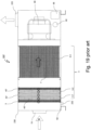
- Fig. 1
- shows an embodiment of a filter system according to the present invention, said filter system comprising a cartridge according to a first exemplary embodiment of the present invention, wherein said cartridge comprises a filter element according to an exemplary embodiment of the present invention;
- Fig. 2
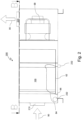
- shows a side view of the filter system of
Fig. 1 in view of section A-A depicted inFig. 3 ; - Fig. 3
- shows a top view of the filter system of
Fig. 1 in view of section B-B ofFig. 2 ; - Fig. 4
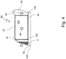
- shows a detailed view of
area 84 depicted inFigure 2 ; - Fig. 5
- shows a detailed view of
area 80 depicted inFigure 3 ; - Fig. 6
- shows a detailed view of
area 82 depicted inFigure 3 , wheredrain openings 53 are shown through a transparent view ofcoalescence medium 40; - Fig. 7
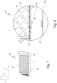
- shows a detailed view of
area 84 depicted inFigure 2 ; - Fig. 8
- shows a detailed view of
area 86 depicted inFigure 2 ; - Fig. 9
- shows in detail the filter element of
Fig. 1 ; - Fig. 10
- shows in detail the cartridge of
Fig. 1 , wheredrain openings 53 are shown through a transparent view ofcoalescence medium 40; - Fig.··11
- shows in detail the corrugated separator of
Fig. 1 ; - Fig. 12
- shows in detail the ground area of the frame of the cartridge of
Fig. 1 ; - Fig. 13
- shows in detail the corrugated separator of
Fig. 1 - Fig. 14
- shows a cartridge according to a second exemplary embodiment of the present invention;
- Fig. 15
- shows in detail the flow of the gas mixture through the cartridge of
Figure 14 as well as the corrugated separator of the cartridge ofFig. 14 ; - Fig. 16
- shows in detail the filter element of the cartridge of
Fig. 14 or of the cartridge ofFig. 1 ; - Fig. 17
- shows in detail the drainage of the separated fluid out of the cartridge of
Fig. 14 ; - Fig. 18
- shows a first embodiment of a filter system according to prior art being designed for a horizontal gas flow; and
- Fig. 19
- shows a second embodiment of a filter system according to prior art being designed for a horizontal gas flow.
- The same reference numerals are used for corresponding parts in
Fig. 1 to Fig. 19 . - In order to avoid unnecessary repetitions, the following description regarding the embodiments, characteristics and advantages of the present invention relates (unless stated otherwise)
- to the first embodiment of the
cartridge 120 according to the present invention (cf.Fig. 1 ) as well as - to the second embodiment of the
cartridge 122 according to the present invention (cf.Figure 14 ). - In
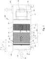
figure 1 is shown an embodiment of a horizontal flow coalescingfilter system 200 comprising apre-separator stage 5, a first embodiment of acartridge 120 according to the the present invention and ahousing 230 to house thepre-separator stage 5 and thecartridge 120. Thefilter system 200 may comprise a housing withmultiple housing sections - a
first housing section 20, comprising afilter system inlet 210, - a
second housing section 21 and athird housing section 22 being arranged to a pre-separator stage, - a
fourth housing section 23, afifth housing section 24 and asixth housing section 25 being arranged to a main-separator stage, - a
seventh housing section 26, being arranged to a post-separator stage and - an
eighth housing section 27, comprising a filter system outlet 220 (cf.figure 1 ). - The
filter element 100 depicted inFigures 1 to 17 is designed for being flowed through by the gas mixture along the horizontal axis X of thefilter element 100 and for separating a dispersed fluid phase from a continuous phase of a gas mixture. It comprises - a vertical axis Y, a horizontal axis X and a depth axis Z perpendicularly to each other,
- a coalescing
filter medium 40 being folded in a sinusoidal or zigzagged manner forming multiple folds, each fold having alength 70 and adepth 72, and -
corrugated separators 42, wherein - at least one of the
corrugated separators 42 is assigned to each fold, - each
corrugated separator 42 comprises sinusoidal or zigzag-shapedcorrugations 46 located in between adjacentlongitudinal surfaces corrugated separator 42. With other words, each corrugation comprises a corrugation vertex being in contact with a first longitudinal surface of the adjacent layers of the fold and a corrugation foot being in contact with a second longitudinal surface of the adjacent layers of the fold. The heights of the corrugations extend perpendicularly to thelongitudinal surfaces longitudinal surfaces filter element 100. - The second embodiment of the
cartridge 122 shown infigure 14 differs from the first embodiment of thecartridge 120 shown infigure 1 only in the orientation of the folds of the coalescingfilter medium 40. As depicted infigures 1 and16 , the folds of the coalescingfilter medium 40 may be arranged in thecartridge 120 lying horizontally, i.e. thelongitudinal surfaces filter element 100. Alternatively, as depicted infigure 14 , the folds of the coalescingfilter medium 40 may be arranged in the cartridge standing horizontally, i.e. thelongitudinal surfaces filter element 100. - Each
corrugation 46 of thecorrugated separators 42 comprises a corrugation depth axis L extending across thedepth 72 of the fold. Said corrugation depth axis L is disposed at an angle offset to the vertical axis Y of thefilter element 100 as well as offset to the depth axis Z of thefilter element 100 as well as offset to the horizontal axis X of thefilter element 100. - With other words, each
corrugated separator 42 is disposed across the depth of the fold being assigned to the respectivecorrugated separator 42 thus that its corrugation vertexes form corrugation vertex lines extending through the depth of the fold and its corrugation feet form corrugation feet lines extending through the depth of the fold, wherein the corrugation vertex lines and the corrugation feet lines are disposed at an slanted angle offset to an axis through the length of the fold being assigned to the respectivecorrugated separator 42. - As depicted in
figures 5, 6 ,9, 10 and16 , the coalescingfilter medium 40 is wound horizontally around thecorrugated separators 42 which leads to aninflow side 102 for the gas mixture, a so called raw side, and to an outflow side, a so called clean side.Figures 15 to 17 show in detail thefilter element 100 incartridge figure 15 , flow of the dispersed fluid phase in the gas mixture is represented by the shadedarrow 90, while flow of the continuous phase of the gas mixture is represented by theclear arrow 90. - The gas mixture, e.g. aerosol/air mixture, is directed generally along
fluid path 90 from theinflow side 102 against thecorrugated separators 42, passes hollow channels formed by the corrugations and flows throughopenings 44, e.g. vent openings, such as vent holes, of thecorrugated separators 42. By passing the hollow channels and by flowing through thevent openings 44 the gas mixture has the first possibility of depositing or separating the dispersed fluid phase. - The angled or oblique orientation of the corrugation depth axis L of the
corrugated separators 42 ensures a distribution of the residual gas mixture to the entire surface of the coalescingfilter medium 40, which performs the fine separation for the residual gas mixture and thus provides a continuous gas phase or clean gas phase having essentially no dispersed fluid phase. - As depicted in
figure 16 , the gas mixture flows through the whole longitudinal section of the coalescingfilter medium 40 extending along the horizontal axis X of thefilter element 100. Specifically, the continuous gas phase is conducted by thecorrugated separator 42 in the raw side, in particular by the corrugations as described above, then flows through thelongitudinal surfaces filter medium 40, to thecorrugated separator 42 in the clean side, and to anoutflow side 104 of thefilter element 100. After leaving thecoalescence filter element 100, the continuous gas phase is optionally further separated by at least onepost cartridge element 7 for separating suspended particles, then flows into the post-separator stage and out of thefilter system 200 viafilter system outlet 220. Saidpost cartridge element 7 may be assigned to a further housing section, e.g. to afifth housing section 24 or to asixth housing section 25 as depicted infigure 1 . Saidpost cartridge element 7 may be a High-Efficiency Particulate Air/Arrestance Filter, a so called HEPA-Filter. Thefilter element 100 and thepost cartridge element 7 may both be assigned to amain separator stage 3, for example to a multi-stage main separator stage comprising e.g. a first main separator stage 3-1, a second main separator stage 3-2 and a third main separator stage 3-3, as depicted infigure 1 or prior artfigure 19 . Thefilter system 200 advantageously does not require multiple coalescence filtermedia 40 or filterelements 100, as is required in the prior art filter system 200' infigure 19 . Thefilter system 200 may comprise a multi-stagemain separator stage 3 comprising thefilter element 100, i.e. main separator stage 3-1, and thepost cartridge element 7, i.e. main separator stage 3-3. - The
filter element 100 may be housed in thefourth housing section 23 orframe 50. Thefilter element 100 may be fit intohousing section 23 orframe 50, or compressed withinhousing section 23 orframe 50, such that movement of thefilter element 100 is minimized when the continuous gas phase is conducted therethrough. Particularly, the coalescingfilter medium 40 may be compressed byhousing section 23 orframe 50, which in turn compressescorrugated separators 42 between thelongitudinal surfaces filter medium 40. Advantageously, compression of thefilter element 100 byhousing section 23 orframe 50 negates the need to bond the corrugated separator to the fold or to bond the coalescingfilter medium 40 to thehousing section 23 orframe 50. - A major advantage of the present invention is that more coalescing
filter medium 40 can be flowed through at the same time than with thefilter mats 40' used in the prior art in the horizontal direction of flow as depicted infigures 18 and19 . - The aerosol mixture separated in this way forms droplets 64 (cf.
figure 8 ,15 and17 ) according to the flow velocity and the separation surfaces of the coalescingfilter medium 40. Saiddroplets 64 move downwards according to gravity, even during the flow of the gas mixture through the coalescingfilter medium 40. For the embodiment depicted infigure 16 , i.e., the first embodiment ofcartridge 120,droplets 64 move according to gravity along the angledcorrugated separators 42 located in the raw side, towardsdrain openings 53. Somedroplets 64 may be entrained within theseparation surface filter medium 40, such that clean air emerges from thelower separation surface Droplets 64 entrained within theseparation surface separation surface filter medium 40 that is adjacent to the bottom 52 of theframe 50, and towardsdrain openings 53. At the bottom orground area 52 of theframe 50 of thecartridge droplets 64 are collected influid reservoir 62, passed through or discharged. - Advantageously, the separated droplets are led out of the
coalescence filter 100 throughdrain openings 53 arranged in the bottom 52 of theframe 50 of thecartridge drain openings 53 are formed to pass through or to penetrate the bottom 52 of theframe 50 of thecartridge drain openings 53, the separateddroplets 64 may be collected in afluid reservoir 62 of thefilter system housing 230 and/or drained out by afluid outlet 232 of thefilter system housing 230. - As depicted in
figures 10 and12 , thedrain openings 53 are advantageously arranged only on the raw side of the coalescingfilter medium 40. Thus, an undesirable bypass is prevented. - The coalescing
filter medium 40 and thecorrugated separators 42 are connected to thedrain openings 53 comprisingbottom 52, e.g. of the perforated bottom, of thecartridge frame 50 is as follows:
Thehorizontal coalescence medium 40, which is wrapped around thecorrugated separators 42, is piled up in the receivingframe 50 with a defined contact pressure until thecartridge frame 50 is completely filled. It may be started with a layer ofcoalescence medium 40 followed by thecorrugated separator 42. Thecorrugated separator 42 is preferably centered on thecoalescence medium 40, another layer of thecoalescence medium 40 is now placed on thecorrugated separator 42 separator again, followed by anothercorrugated separator 42, and so on. Thecoalescence medium 40 or a part of thecoalescence medium 40, e.g. the starting layer of thecoalescence medium 40, may be bonded to theframe 50. - As depicted in
figure 10 , this winding creates open and closed sides of the folds, where thedrain openings 53 are advantageously arranged at the frame bottom 52 in the area of the open side, i.e. in the area of the raw side, in the direction ofhorizontal flow 90. - The
drain openings 53 can be essentially even distributed over the frame bottom 52 as depicted infigure 14 . - As depicted in
figure 12 , thedrain openings 53 are advantageously only arranged before the last third of the horizontal length of the coalescence medium in the direction of thegas flow 90 or of theoutflow side 104 or clean side of thefilter element 100. Thus, in the horizontal flow direction, preferably up to one third of the cartridge frame bottom 52 is designed withoutdrain openings 53. This arrangement of thedrain openings 53 is preferably adjusted in conjunction with the selected angle of the corrugation depth axis L of thecorrugated separators 42. - The
drain openings 53 themselves are preferably small, like perforations. However, the size of the drain openings should be large enough to be unsusceptible to dirt. - Independently thereof or in connection therewith, the total area of the
drain openings 53 is preferably smaller than the total area of the open sides of the folds at theinflow side 102 of thefilter element 100. - The
filter system 200 or filter element depicted infigures 1 to 17 is designed for being flowed through by a flow rate of the gas mixture of up to 2000 cubic meter per hour. In an example, the flow rate of the gas mixture may be in the range of about 400 cubic meter per hour to 2000 cubic meter per hour. - The
filter system 200 may comprise adifferential pressure indicator 60 for indicating pressure differences, acontrol device 66 for controllingfilter system 200 and aventilator 68 for providing thehorizontal gas flow 90. Thedifferential pressure indicator 60 may identify the pressure drop of the raw gas entering thefilter system 200, e.g. before thepre-separator stage 5, and the clean gas exiting thefilter system 200, e.g. after themain separator stage 3. Thedifferential pressure indicator 60 may feed its data to thecontrol device 66. Thecontrol device 66 may control the strength ofventilator 68, based on data received such as from thedifferential pressure indicator 60, in order to maintain thehorizontal gas flow 90 at the desired flow rate of the gas mixture. - The surface area of the coalescing
filter medium 40' of the filter system 200' according to prior art, as depicted infigures 18 and19 amounts approximately 0,75 square meter. - The coalescence filter medium 40 depicted in
figures 1 to 17 amounts in thesame space 6,5 square meter due to the folding. - In a nutshell, the coalescence filter medium 40 depicted in
figures 1 to 17 relates to a horizontal flow coalescing aerosol filter element, mainly designed for separating oil/emulsion aerosols, wherein thiscoalescence filter medium 40 allows for smaller dimensions, lighter weight and lower manufacturing costs compared to the coalescence filter medium 40' according to prior art. -
- 3
- main separator stage
- 3-1
- first main separator stage
- 3-2
- further main separator stage, in particular second main separator stage
- 3-3
- further main separator stage, in particular third main separator stage
- 5
- pre-separator stage, in particular pre-separator element for separating coarse dirt particles, for example metal mash
- 7
- post-cartridge stage, in particular post-cartridge element for separating suspended particles, for example H[igh-]Efficiency ]P[articulate ]A[ir/Arrestance] Filter, preferably being assigned to the main separator stage, for example to a second or third main separator stage
- 20
- first housing section
- 21
- second housing section
- 22
- third housing section
- 23
- fourth housing section
- 24
- fifth housing section
- 25
- sixth housing section,
- 26
- seventh housing section
- 27
- eighth housing section
- 28
- ninth housing section
- 40
- coalescing filter medium or coalescence filter medium, for example folded multilayered glass fibre medium, for separating a dispersed fluid phase from a continuous phase of a gas mixture, in particular for separating oil aerosol particles from raw gas, for example for separating cooling lubricant aerosol articles and/or release agent aerosol particles from the exhaust air of at least one production machine
- 40'
- coalescing filter medium or coalescence filter medium, in particular coalescence filter mat, according to prior art used for horizontal flow direction
- 42
- corrugated separator, in particular angulated corrugated separator, for example spacer for supporting the
longitudinal surfaces - 44
- corrugated separator opening, in particular vent whole or perforation of the
corrugated separator 42 - 46
- corrugation of the
corrugated separator 21 - 50
- frame of the
cartridge 120 for receiving the coalescingfilter medium 40 and thecorrugated separators 42, in particular cuboid frame of thecartridge 120 - 52
- ground area or bottom of the frame of the
cartridge 120, in particular perforated bottom - 53
- drain opening of the
frame 50 for draining fluid out of thecartridge 120, in particular fluid drain - 60
- differential pressure indicator of the
filter system 200 - 62
- fluid reservoir of the
filter system 200, in particular collection volume for receiving separated fluid or liquid - 64
- fluid droplet
- 66
- control device of the
filter system 200 - 68
- ventilator or fan
- 70
- length of a fold
- 72
- depth of the fold
- 74
- longitudinal surface of a fold
- 76
- further longitudinal surface of a fold
- 80
- area adjacent to the ground area of the
frame 52 of thecartridge 120 offigure 3 , saidarea 80 is depicted inFigure 5 in detail - 82
- area adjacent to the ground area of the
frame 52 of thecartridge 120 offigure 3 , saidarea 82 depicted inFigure 6 in detail - 84
- area adjacent to the ground area of the
frame 52 of thecartridge 120 offigure 2 , saidarea 84 is depicted inFigure 4 in detail - 86
- area adjacent to the ground area of the
frame 52 of thecartridge 120 offigure 2 , saidarea 86 is depicted inFigures 7 and10 in detail - 90
- flow of gas mixture or fluid path
- 100
- filter element, in particular coalescing filter element
- 102
- inflow side of the
filter element 100 - 104
- outflow side of the
filter element 100 - 106
- fold tip
- 120
- cartridge, in particular filter cassette, first embodiment cf.
Fig. 1 - 122
- cartridge, in particular filter cassette, second embodiment cf.
Fig. 14 - 200
- filter system, in particular separator, e.g. coalescing aerosol filter system, for separating a dispersed fluid phase from a continuous phase of a gas mixture, in particular for separating oil aerosol particles from raw gas, in particular from the exhaust air of at least one production machine, in particular of a cutting production machine
- 200'
- horizontal flow coalescing filter system according to prior art cf.
figures 18 and19 - 210
- filter system inlet, in particular raw gas inlet
- 220
- filter system outlet, in particular clean gas outlet
- 230
- housing of the
filter system 200 - 232
- fluid outlet of the
filter system housing 230, in particular of a ground area of thefilter system housing 230 - L
- corrugation depth axis, in particular crest line of the sinusoidal or zig-zag formed corrugation, e.g. crest line of the hollow channel formed by the corrugation
- X
- horizontal axis of the
filter element 100 - Y
- vertical axis of the
filter element 100 - Z
- depth axis or sagittal axis of the
filter element 100
Claims (15)
- Filter element (100) adapted to separate a dispersed fluid phase from a continuous phase of a gas mixture, the filter element (100) comprising- a horizontal axis (X), a vertical axis (Y) and a depth axis (Z) perpendicularly to the each other,- a coalescing filter medium (40) being folded in a sinusoidal or zigzagged manner forming at least one fold having a length (70) and a depth (72), and- at least one corrugated separator (42) comprising sinusoidal or zigzag-shaped corrugations (46) located in between adjacent longitudinal surfaces (74, 76) of the fold, wherein the heights of the corrugations extend perpendicularly to the length (70) of the fold and wherein each corrugation (46) comprises a corrugation depth axis (L) extending across the depth (72) of the fold, characterized in, that- the corrugation depth axis (L) is disposed at an angle offset to the horizontal axis (X) as well as offset to the vertical axis (Y) as well as offset to the depth axis (Z) and- the longitudinal surfaces (74, 76) of the fold extend along the horizontal axis (X) of the filter element (100) from an inflow side (102) of the filter element (100) to an outflow side (104) of the filter element (100).
- Filter element according to claim 1, characterized in that the corrugation depth axis (L) is disposed at an angle of about 20 degrees to about 70 degrees, in particular of about 25 degrees to about 55 degrees, for example of about 30 degrees, to the vertical axis (Y) of the filter element (100).
- Filter element according to claim 1 or 2, characterized in that the corrugations (46) are comprising at least one corrugated separator opening (44), in particular at least one perforation, being designed for being streamed through by the gas mixture streaming along the horizontal axis (X) of the filter element (100).
- A filter element according to at least one of claims 1 to 3, characterized in that each corrugation (46) extends across the depth (72) of the fold in such way, that at least one hollow channel is provided through the depth (72) of the fold, wherein the corrugation depth axis (L) of the corrugation (46) is disposed at the angle for enhancing the fluid being separated from the gas mixture to be drained by gravity.
- A filter element according to at least one of claims 1 to 4, characterized in that the longitudinal surfaces (74, 76) of the fold extend between the- horizontal filter element axis (X) and the depth filter element axis (Z) or- horizontal filter element axis (X) and the vertical filter element axis (Y).
- A filter element according to at least one of claims 1 to 5, characterized in that the filter element (100) is designed for being flowed through by a flow rate of the gas mixture of up to 2000 cubic meter per hour, for example by a flow rate of the gas mixture in the range of about 400 cubic meter per hour to 2000 cubic meter per hour.
- A filter element according to at least one of claims 1 to 6, characterized in that- the corrugated separators (42) comprise, in particular essentially consist of, at least one metal material, in particular at least one material comprising aluminum, e.g. steel, such as unalloyed structural steel of grade S235, and/or at least one combustible material, in particular combustible synthetic material and/or combustible plant fibre material, e.g. cellulose fibre material, and/or- the coalescing filter medium (40) comprises, in particular essentially consists of, at least one fibrous material, such as at least one synthetic fibre material and/or at least one glass fibre material and/or at least one plant fibre material.
- A cartridge (120; 122) comprising at least one frame (50) for receiving at least one filter element comprising at least one coalescing filter medium (40) with at least one corrugated separator (42) integrated into at least one fold of the coalescing filter medium (40), characterized in that- the filter element is a filter element (100) according to at least one of claims 1 to 8 and- the frame (50) comprises an essentially horizontal ground area (52) comprising at least one frame drain opening (53) for draining fluid being separated by the filter element (100).
- Cartridge according to claim 8, characterized in that the at least one filter element (100) is held within the frame (50) by means of a press fit, such that the at least one corrugated separator (42) is compressed between the fold of the coalescing filter medium (40).
- Cartridge according to claim 8 or 9, characterized in that the coalescing filter medium (40) comprises at least one gas mixture inlet area at the inflow side (102) of the filter element (100), wherein the total area of the at least one frame drain opening (53) is smaller than the total area of the at least one gas mixture inlet.
- The cartridge according to at least one of claims 8 to 10, characterized in that- the fold comprises longitudinal surfaces (74, 76) being connected by a fold tip (106), wherein the area between two longitudinal surfaces (74, 76) being connected by a fold tip (106) facing the inflow side (102) of the filter element 100 forms the clean side of the coalescing filter medium (40) and the area between two longitudinal surfaces (74, 76) being connected by a fold tip (106) facing the outflow side (104) of the filter element 100 of the filter element 100 forms the raw side of the coalescing filter medium (40), and- the frame drain opening (53) is only arranged in the area of the raw side of the coalescing filter medium (40).
- Cartridge according to at least one of claims 8 to 11, characterized in that the frame drain opening (53) is arranged in flow direction of the gas mixture only in the first two thirds of the area of the horizontal ground area (··52).
- Filter system (200) comprising a pre-separator stage (5), a cartridge (120; 122) and a housing (230) to house the pre-separator stage (5) and the cartridge (120; 122), characterized in that the cartridge (120; 122) is a cartridge (120; 122) according to at least one of claims 8 to 12, wherein a continuous phase of a gas mixture comprising a dispersed fluid phase that entered a filter system inlet (210) of the housing (230) flows horizontally through the pre-separator stage (5) and through the cartridge (120; 122), and a continuous gas phase having essentially no dispersed fluid phase exits the filter system (200) through an filter system outlet (220) of the housing (230).
- Filter system according to claim 13, characterized by a post-cartridge stage (7) of filter class ten or higher according to European Norm EN 1822.
- Use of the filter element of at least one of claims 1 to 7 in a cartridge (120; 122) of at least one of claims 8 to 12 or a filter system (200) according to claim 13 or 14.
Priority Applications (3)
| Application Number | Priority Date | Filing Date | Title |
|---|---|---|---|
| EP22161621.2A EP4241868A1 (en) | 2022-03-11 | 2022-03-11 | Filter element, cartridge and filter system |
| CN202380012643.5A CN117651599A (en) | 2022-03-11 | 2023-03-06 | Filter element, cartridge and filter system |
| PCT/IB2023/052056 WO2023170538A1 (en) | 2022-03-11 | 2023-03-06 | Filter element, cartridge and filter system |
Applications Claiming Priority (1)
| Application Number | Priority Date | Filing Date | Title |
|---|---|---|---|
| EP22161621.2A EP4241868A1 (en) | 2022-03-11 | 2022-03-11 | Filter element, cartridge and filter system |
Publications (1)
| Publication Number | Publication Date |
|---|---|
| EP4241868A1 true EP4241868A1 (en) | 2023-09-13 |
Family
ID=80738920
Family Applications (1)
| Application Number | Title | Priority Date | Filing Date |
|---|---|---|---|
| EP22161621.2A Pending EP4241868A1 (en) | 2022-03-11 | 2022-03-11 | Filter element, cartridge and filter system |
Country Status (3)
| Country | Link |
|---|---|
| EP (1) | EP4241868A1 (en) |
| CN (1) | CN117651599A (en) |
| WO (1) | WO2023170538A1 (en) |
Citations (3)
| Publication number | Priority date | Publication date | Assignee | Title |
|---|---|---|---|---|
| JPS57152925U (en) * | 1981-03-20 | 1982-09-25 | ||
| US5395411A (en) * | 1992-07-31 | 1995-03-07 | Toyo Boseki Kabushiki Kaisha | Filter for air cleaning |
| WO2021185477A1 (en) | 2020-03-17 | 2021-09-23 | Mann+Hummel Life Sciences & Environment Holding Singapore Pte. Ltd. | Separation element, filter system, and method for producing a separation element |
-
2022
- 2022-03-11 EP EP22161621.2A patent/EP4241868A1/en active Pending
-
2023
- 2023-03-06 WO PCT/IB2023/052056 patent/WO2023170538A1/en unknown
- 2023-03-06 CN CN202380012643.5A patent/CN117651599A/en active Pending
Patent Citations (3)
| Publication number | Priority date | Publication date | Assignee | Title |
|---|---|---|---|---|
| JPS57152925U (en) * | 1981-03-20 | 1982-09-25 | ||
| US5395411A (en) * | 1992-07-31 | 1995-03-07 | Toyo Boseki Kabushiki Kaisha | Filter for air cleaning |
| WO2021185477A1 (en) | 2020-03-17 | 2021-09-23 | Mann+Hummel Life Sciences & Environment Holding Singapore Pte. Ltd. | Separation element, filter system, and method for producing a separation element |
Non-Patent Citations (3)
| Title |
|---|
| "AFS - starke Leistung, reine Luft; Luftreinigungsgerate und -Anlagen zur Absaugung von Ol- und Emulsionsnebel, lufttechnischer Anlagenbau, raumlufttechnische Anlagen, betrieblicher Umweltschutz", vol. 14, 2018, pages: 74547 |
| N N: "AFS - starke Leistung, reine Luft Luftreinigungsgeräte und -Anlagen zur Absaugung von Öl- und Emulsionsnebel, lufttechnischer Anlagenbau, raumlufttechnische Anlagen, betrieblicher Umweltschutz", 1 January 2018 (2018-01-01), pages 1 - 16, XP055907856, Retrieved from the Internet <URL:https://www.afs-airfilter.de/fileadmin/Download/Prospekt/AFS-Prospekt_2018.pdf> [retrieved on 20220401] * |
| N N: "IFMC 500", 1 January 2017 (2017-01-01), pages 1 - 1, XP055907858, Retrieved from the Internet <URL:https://www.ifs-industriefilter.de/fileadmin/upload/Produktdatenblaetter_DE_ENG/Industriefilter_mechanisch/Produktblatt_IFMC_500_01.pdf> [retrieved on 20220401] * |
Also Published As
| Publication number | Publication date |
|---|---|
| WO2023170538A1 (en) | 2023-09-14 |
| CN117651599A (en) | 2024-03-05 |
Similar Documents
| Publication | Publication Date | Title |
|---|---|---|
| US4878929A (en) | Liquid-gas separator | |
| EP1855781B1 (en) | Fiber collecting media strip for a mist eliminator | |
| US7416576B2 (en) | Fiber bed assembly and fiber bed therefor | |
| US9005340B2 (en) | Fiber bed assembly including a re-entrainment control device for a fiber bed mist eliminator | |
| US20050235617A1 (en) | Mist collector arrangement and methods | |
| CA2549105C (en) | Apparatus and method for enhanced droplet collection in gas flows | |
| EP3458174B1 (en) | Filter assembly and method for filtration | |
| JP2012163096A (en) | Moisture diversion apparatus for air inlet system and method | |
| WO2010051091A1 (en) | Compact fiber bed mist eliminator | |
| US8858669B2 (en) | Oil coalescing filter | |
| RU2469771C1 (en) | Separator for gas purification | |
| EP4241868A1 (en) | Filter element, cartridge and filter system | |
| US7344580B2 (en) | Filter unit | |
| WO1998035744A1 (en) | Apparatus and method for removing entrained liquid from gas or air | |
| JP2005007363A (en) | Cylindrical mist filter and mist collector using the same | |
| CN215026860U (en) | Coalescence-separation ware of band wind separation function | |
| EP3894291B1 (en) | Effluent processing apparatus and method for a vehicle air brake charging system | |
| JP3452334B2 (en) | Oil separator | |
| WO2004108251A1 (en) | Fiber bed element for fiber bed mist eliminator | |
| CN116078072A (en) | Apparatus and method for separating oil particles from an air stream | |
| RU2136351C1 (en) | Cartridge filter | |
| MXPA99007495A (en) | Apparatus and method for removing entrained liquid from gas or air | |
| DK154007B (en) | Liquid-air-separator |
Legal Events
| Date | Code | Title | Description |
|---|---|---|---|
| PUAI | Public reference made under article 153(3) epc to a published international application that has entered the european phase |
Free format text: ORIGINAL CODE: 0009012 |
|
| STAA | Information on the status of an ep patent application or granted ep patent |
Free format text: STATUS: THE APPLICATION HAS BEEN PUBLISHED |
|
| AK | Designated contracting states |
Kind code of ref document: A1 Designated state(s): AL AT BE BG CH CY CZ DE DK EE ES FI FR GB GR HR HU IE IS IT LI LT LU LV MC MK MT NL NO PL PT RO RS SE SI SK SM TR |
|
| STAA | Information on the status of an ep patent application or granted ep patent |
Free format text: STATUS: REQUEST FOR EXAMINATION WAS MADE |
|
| 17P | Request for examination filed |
Effective date: 20231229 |
|
| RBV | Designated contracting states (corrected) |
Designated state(s): AL AT BE BG CH CY CZ DE DK EE ES FI FR GB GR HR HU IE IS IT LI LT LU LV MC MK MT NL NO PL PT RO RS SE SI SK SM TR |
|
| GRAP | Despatch of communication of intention to grant a patent |
Free format text: ORIGINAL CODE: EPIDOSNIGR1 |
|
| STAA | Information on the status of an ep patent application or granted ep patent |
Free format text: STATUS: GRANT OF PATENT IS INTENDED |
|
| GRAS | Grant fee paid |
Free format text: ORIGINAL CODE: EPIDOSNIGR3 |
|
| INTG | Intention to grant announced |
Effective date: 20240220 |
|
| GRAA | (expected) grant |
Free format text: ORIGINAL CODE: 0009210 |
|
| STAA | Information on the status of an ep patent application or granted ep patent |
Free format text: STATUS: THE PATENT HAS BEEN GRANTED |