EP3894291B1 - Effluent processing apparatus and method for a vehicle air brake charging system - Google Patents
Effluent processing apparatus and method for a vehicle air brake charging system Download PDFInfo
- Publication number
- EP3894291B1 EP3894291B1 EP19832778.5A EP19832778A EP3894291B1 EP 3894291 B1 EP3894291 B1 EP 3894291B1 EP 19832778 A EP19832778 A EP 19832778A EP 3894291 B1 EP3894291 B1 EP 3894291B1
- Authority
- EP
- European Patent Office
- Prior art keywords
- effluent
- oil
- water
- effluent mixture
- chamber
- Prior art date
- Legal status (The legal status is an assumption and is not a legal conclusion. Google has not performed a legal analysis and makes no representation as to the accuracy of the status listed.)
- Active
Links
- 238000012545 processing Methods 0.000 title claims description 44
- 238000000034 method Methods 0.000 title claims description 15
- XLYOFNOQVPJJNP-UHFFFAOYSA-N water Substances O XLYOFNOQVPJJNP-UHFFFAOYSA-N 0.000 claims description 96
- 239000000203 mixture Substances 0.000 claims description 87
- 238000010926 purge Methods 0.000 claims description 21
- 230000002093 peripheral effect Effects 0.000 claims description 2
- 239000003921 oil Substances 0.000 description 82
- 239000002245 particle Substances 0.000 description 15
- 239000000463 material Substances 0.000 description 14
- 239000003570 air Substances 0.000 description 10
- 239000002274 desiccant Substances 0.000 description 4
- 238000013461 design Methods 0.000 description 4
- 238000010586 diagram Methods 0.000 description 4
- 230000002745 absorbent Effects 0.000 description 3
- 239000002250 absorbent Substances 0.000 description 3
- 238000007605 air drying Methods 0.000 description 2
- 239000000356 contaminant Substances 0.000 description 2
- 230000005484 gravity Effects 0.000 description 2
- 230000003116 impacting effect Effects 0.000 description 2
- 239000007788 liquid Substances 0.000 description 2
- 239000003595 mist Substances 0.000 description 2
- 238000012544 monitoring process Methods 0.000 description 2
- 238000004140 cleaning Methods 0.000 description 1
- 230000003247 decreasing effect Effects 0.000 description 1
- 238000000151 deposition Methods 0.000 description 1
- 239000000835 fiber Substances 0.000 description 1
- 238000001914 filtration Methods 0.000 description 1
- 239000008187 granular material Substances 0.000 description 1
- 238000004519 manufacturing process Methods 0.000 description 1
- 239000010705 motor oil Substances 0.000 description 1
- 229920000728 polyester Polymers 0.000 description 1
- 230000002265 prevention Effects 0.000 description 1
- 238000012827 research and development Methods 0.000 description 1
- 230000000717 retained effect Effects 0.000 description 1
Images


Classifications
-
- B—PERFORMING OPERATIONS; TRANSPORTING
- B01—PHYSICAL OR CHEMICAL PROCESSES OR APPARATUS IN GENERAL
- B01D—SEPARATION
- B01D46/00—Filters or filtering processes specially modified for separating dispersed particles from gases or vapours
- B01D46/0027—Filters or filtering processes specially modified for separating dispersed particles from gases or vapours with additional separating or treating functions
- B01D46/003—Filters or filtering processes specially modified for separating dispersed particles from gases or vapours with additional separating or treating functions including coalescing means for the separation of liquid
- B01D46/0031—Filters or filtering processes specially modified for separating dispersed particles from gases or vapours with additional separating or treating functions including coalescing means for the separation of liquid with collecting, draining means
-
- B—PERFORMING OPERATIONS; TRANSPORTING
- B60—VEHICLES IN GENERAL
- B60T—VEHICLE BRAKE CONTROL SYSTEMS OR PARTS THEREOF; BRAKE CONTROL SYSTEMS OR PARTS THEREOF, IN GENERAL; ARRANGEMENT OF BRAKING ELEMENTS ON VEHICLES IN GENERAL; PORTABLE DEVICES FOR PREVENTING UNWANTED MOVEMENT OF VEHICLES; VEHICLE MODIFICATIONS TO FACILITATE COOLING OF BRAKES
- B60T17/00—Component parts, details, or accessories of power brake systems not covered by groups B60T8/00, B60T13/00 or B60T15/00, or presenting other characteristic features
- B60T17/002—Air treatment devices
- B60T17/004—Draining and drying devices
-
- B—PERFORMING OPERATIONS; TRANSPORTING
- B01—PHYSICAL OR CHEMICAL PROCESSES OR APPARATUS IN GENERAL
- B01D—SEPARATION
- B01D17/00—Separation of liquids, not provided for elsewhere, e.g. by thermal diffusion
- B01D17/02—Separation of non-miscible liquids
- B01D17/0208—Separation of non-miscible liquids by sedimentation
- B01D17/0211—Separation of non-miscible liquids by sedimentation with baffles
-
- B—PERFORMING OPERATIONS; TRANSPORTING
- B01—PHYSICAL OR CHEMICAL PROCESSES OR APPARATUS IN GENERAL
- B01D—SEPARATION
- B01D45/00—Separating dispersed particles from gases or vapours by gravity, inertia, or centrifugal forces
- B01D45/04—Separating dispersed particles from gases or vapours by gravity, inertia, or centrifugal forces by utilising inertia
- B01D45/08—Separating dispersed particles from gases or vapours by gravity, inertia, or centrifugal forces by utilising inertia by impingement against baffle separators
-
- B—PERFORMING OPERATIONS; TRANSPORTING
- B60—VEHICLES IN GENERAL
- B60T—VEHICLE BRAKE CONTROL SYSTEMS OR PARTS THEREOF; BRAKE CONTROL SYSTEMS OR PARTS THEREOF, IN GENERAL; ARRANGEMENT OF BRAKING ELEMENTS ON VEHICLES IN GENERAL; PORTABLE DEVICES FOR PREVENTING UNWANTED MOVEMENT OF VEHICLES; VEHICLE MODIFICATIONS TO FACILITATE COOLING OF BRAKES
- B60T13/00—Transmitting braking action from initiating means to ultimate brake actuator with power assistance or drive; Brake systems incorporating such transmitting means, e.g. air-pressure brake systems
- B60T13/10—Transmitting braking action from initiating means to ultimate brake actuator with power assistance or drive; Brake systems incorporating such transmitting means, e.g. air-pressure brake systems with fluid assistance, drive, or release
- B60T13/66—Electrical control in fluid-pressure brake systems
- B60T13/68—Electrical control in fluid-pressure brake systems by electrically-controlled valves
- B60T13/683—Electrical control in fluid-pressure brake systems by electrically-controlled valves in pneumatic systems or parts thereof
-
- B—PERFORMING OPERATIONS; TRANSPORTING
- B60—VEHICLES IN GENERAL
- B60T—VEHICLE BRAKE CONTROL SYSTEMS OR PARTS THEREOF; BRAKE CONTROL SYSTEMS OR PARTS THEREOF, IN GENERAL; ARRANGEMENT OF BRAKING ELEMENTS ON VEHICLES IN GENERAL; PORTABLE DEVICES FOR PREVENTING UNWANTED MOVEMENT OF VEHICLES; VEHICLE MODIFICATIONS TO FACILITATE COOLING OF BRAKES
- B60T17/00—Component parts, details, or accessories of power brake systems not covered by groups B60T8/00, B60T13/00 or B60T15/00, or presenting other characteristic features
- B60T17/02—Arrangements of pumps or compressors, or control devices therefor
Definitions
- the present application relates to vehicle air brake charging systems and is particularly directed to an effluent processing apparatus and method for a vehicle air brake charging system, such as a truck air brake charging system.
- a truck air brake charging system includes a vehicle air compressor which builds air pressure for an air braking system.
- the compressor is typically lubricated by an engine oil supply.
- a governor controls system air pressure between a preset maximum and minimum pressure level by monitoring the air pressure in a supply reservoir. When the supply reservoir air pressure becomes greater than that of a preset "cut-out” setting of the governor, the governor controls the compressor to stop the compressor from building air and also causes an air dryer downstream from the compressor to go into a purge mode. As the supply reservoir air pressure drops to a preset "cut-in” setting of the governor, the governor returns the compressor back to building air and the air dryer to air drying mode.
- the air dryer is an in-line filtration system that removes both water vapor and oil droplets from the compressor discharge air after it leaves the compressor. This results in cleaner, drier air being supplied to the air braking system, and aids in the prevention of air line and component freeze ups in winter weather.
- the air dryer typically uses a replaceable cartridge containing a desiccant material and an oil separator. Most of the oil droplets are removed by the oil separator as the air passes into the air dryer. The air then moves through the desiccant material which removes most of the water vapor.
- the governor makes the compressor stop building air and allows the air dryer's "purge cycle" to begin.
- the desiccant material is regenerated (i.e., its ability to remove water is renewed) by a reversal of the saturation process.
- a small amount of dry air passes back through the desiccant material and the water that has been collected, as well as any oil droplets collected by the oil separator, are purged out through a purge valve to atmosphere. Since the purged air from the purge valve contains oil droplets, this results in depositing of oil onto roadways by the truck.
- US 2004/094036 A1 discloses an effluent processing apparatus with a purge air cleaner being a canister having an internal cavity filled with an absorbent material to remove oil form the purge flow, and an exhaust opening allowing the cleaned purge air to be directed to atmosphere, where the path from a purge valve to the exhaust opening requires the purge air to flow through the absorbent material.
- the absorbent material can for example be a porous fixed bed inside the canister or a corrugated sheet or bed of granulated material.
- an effluent processing apparatus comprises a top housing portion that defines a substantially cylinder-shaped chamber and an effluent channel along which an effluent flows from a centrally-disposed inlet port into a center portion of the chamber coalescing element arranged to separate oil and water from an effluent mixture containing air, oil, and water from a purge valve of an air dryer.
- the coalescing element includes a plurality of members which define a predefined pattern of paths along which the effluent mixture flows to separate oil and water therefrom.
- the effluent processing apparatus further comprises a deflector plate with a cone-shaped protrusion supported on a bottom housing portion, and the plurality of members comprise a predefined pattern of pleats which are arranged to provide the predefined pattern of paths through which the effluent mixture flows to separate oil and water therefrom, wherein the cone-shaped protrusion of the deflector redirects the incoming vertical-flowing stream horizontally outwards toward the pleats of the coalescing element.
- an effluent processing apparatus for a vehicle air brake charging system having an air dryer purge valve through which an effluent containing a mixture of air, oil, and water flows in a flow direction.
- the effluent processing apparatus comprises a coalescing element arranged to separate oil and water from the effluent mixture to provide an air stream substantially devoid of oil.
- the coalescing element is oriented parallel with the flow direction of the effluent mixture such that the effluent mixture flows substantially around or substantially along the coalescing element.
- a method of operating an effluent processing apparatus to separate oil and water from a flow of effluent mixture containing air, oil, and water.
- the method comprises receiving the flow of effluent mixture in a first direction into a center portion of the chamber and redirecting the flow of effluent mixture from the center portion of the chamber in a second direction which is transverse to the first direction and towards an outer perimeter portion of the chamber.
- the method also comprises passing the flow of effluent mixture along a predefined pattern of paths to separate oil and water from the effluent mixture as the effluent mixture flows from the center portion of the chamber to the outer perimeter portion of the chamber.
- the method further comprises temporarily retaining the separated oil to provide a clean stream of air and water devoid of oil that flows into the outer peripheral chamber and exhausting the clean stream from the outer perimeter portion of the chamber to atmosphere.
- Vehicle air brake charging system 100 includes an air compressor 102 that generates compressed air in conventional manner. Structure and operation of air compressors are known and, therefore, will not be described.
- a first discharge line 109 is pneumatically connected between the compressor 102 and an air dryer 108.
- a second discharge line 110 is pneumatically connected between the air dryer 108 and a supply reservoir 112.
- Air supply line 114 is pneumatically connected between the supply reservoir 112 and air braking system and air accessories (not shown) of the vehicle.
- a governor 120 controls system air pressure between a preset maximum and minimum pressure level by monitoring the air pressure in pneumatic control line 122 from the supply reservoir 112. When air pressure in the supply reservoir 112 becomes greater than that of a preset "cut-out” setting of the governor 120, the governor controls the compressor 102 on pneumatic control line 124 to stop the compressor from building air. The governor 120 also controls a purge valve 126 on pneumatic control line 128 to purge air from the air dryer 108 in a purge mode. When air pressure in the supply reservoir 112 drops to a preset "cut-in” setting of the governor 120, the governor returns the compressor 102 back to building air and the air dryer 108 to an air drying mode.
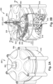
- FIG. 2A a perspective view of the effluent processing apparatus 200 shown in Fig. 1 is illustrated.
- Fig. 2B is a perspective view similar to Fig. 2A with portions removed to show a coalescing element 250 within the effluent processing apparatus 200.
- Fig. 2C is a cross-sectional view taken approximately along line 2C-2C shown in Fig. 2B .
- the effluent processing apparatus 200 includes a centrally-disposed inlet port 202 through which effluent containing a mixture of air, oil, and water from the purge valve 126 ( Fig. 1 ) of the air dryer 108 can be received.
- the effluent may be received from any device that collects air, water, and contaminants.
- the effluent processing apparatus 200 includes a top housing portion 204 that defines a substantially cylinder-shaped chamber 206 and an effluent channel 208 along which the effluent flows from the inlet port 202 into a center portion of the chamber 206.
- the effluent processing apparatus 200 also includes a bottom housing portion 210 that defines an outlet port 212 and a sump 214 into which separated oil and water flows.
- the sump 214 is removable and replaceable, and contains oil-holding media (not shown) that may include a sponge material, for example, to retain the separated oil. Other oil-holding media can be used.
- the effluent processing apparatus 200 may be affixed directly to an air dryer or may be located remotely.
- the effluent processing apparatus 200 is intended to be mounted vertically (best shown in Fig. 2C ) to promote the downward flow of separated oil and water from the effluent channel 208.
- Example overall physical dimensions of the effluent processing apparatus 200 are about 10 inches (25.4 centimeters) in diameter and about eight inches (20.3 centimeters) in height. A minimum diameter would be about five inches (12.7 centimeters) to provide a sufficient flow path and to avoid back pressure.
- the effluent processing apparatus 200 may further include a deflector plate 220 which is supported on the bottom housing portion 210, as best shown in Fig. 2C .
- the deflector plate 220 has a shape like a disc, and includes a cone-shaped protrusion 222 located at center of the disc.
- the cone-shaped protrusion 222 points towards the center portion of the chamber 206 and is centrally-aligned with the effluent channel 208.
- a baffled channel 224 is defined between the top housing portion 204 and the deflector plate 220.
- the effluent processing apparatus 200 also includes the coalescing element 250.
- the coalescing element 250 is located in the chamber 206, and is supported by the top housing 204. More specifically, as best shown in Fig. 2C , the coalescing element 250 is press-fit into a substantially donut-shaped channel 226 in the top housing portion 204.
- FIG. 2D an enlarged top perspective view of the coalescing element 250 shown in Figs. 2B and 2C constructed in accordance with an embodiment is illustrated.
- Fig. 2E is a bottom perspective view looking slightly up from the bottom side and in the direction approximately along line 2E-2E shown in Fig. 2D .
- Fig. 2F is a bottom elevational view looking approximately along line 2F-2F shown in Fig. 2E .
- the coalescing element 250 includes a ring member 252 that has a general shape of an internal-toothed lock washer.
- the ring member 252 is press-fit into the substantially donut-shaped channel 226 in the top housing portion 204.
- the number and width of the tooth patterns can vary with desired design specifications.
- the ring member 252 should not take up more than 50% of the volume of the chamber 206.
- the coalescing element 250 is arranged to separate oil and water from the effluent mixture containing air, oil, and water from the purge valve 126 of the air dryer 108 ( Fig. 1 ).
- the coalescing element 250 includes a plurality of members 260 which define a predefined pattern of paths along which the effluent mixture flows to separate oil and water therefrom.
- the plurality of members 260 comprise a predefined pattern of bristles which are arranged to provide a predefined pattern of paths along which the effluent mixture flows to separate oil and water therefrom.
- the bristles 260 comprise a plastic material such as a polyester material having fibers, for example.
- Each of the bristles 260 is rod-shaped and is inserted into the ring member 252.
- each of the bristles 260 is suspended substantially vertically from the ring member 252.
- the bristles 260 are packed together and arranged in a pattern to form a shape corresponding to the shape of the ring member 252, which is the shape of an internal-toothed lock washer, as best shown in Fig. 2F .
- the profile of the ring member 252 can have any shape, such as the tooth shape disclosed herein. As another example, the profile of the ring member 252 may have a smooth shape. Moreover, it is conceivable that the ring member 252 not be used and eliminated. In this case, the bristles 260 can be inserted into holes that are directly drilled into the top housing portion 204.
- the bristles 260 are packed with a density such that the horizontal-flowing stream can flow along the predefined pattern of paths with minimal back pressure as drops of oil and drops of water are coalescing onto the material of the bristles 260.
- the coalesced liquids flow downwards by gravity force through floor openings in the deflector plate 220 into the sump 214.
- the oil-holding media (not shown) in the sump 214 holds the separated oil until the oil-holding media or the sump 214 or both, are replaced.
- the separated water exhausts and drains out through the outlet port 212 to return the water to atmosphere.
- the bristles 260 may be arranged relative to each other in a number of different geometries to promote secondary flows that would enhance their collection efficiency.
- the bristles 260 may be arranged relative to each other in a triangular-shaped geometry.
- the bristles 260 may be arranged relative to each other in a smooth-shaped geometry. Other geometries for the arrangement of the bristles 260 relative to each other are possible.
- clean air i.e., the air which is now substantially devoid of oil
- the clean air has water mist, and flows through the baffled channel 224 to atmosphere, as best shown by the arrow lines designated "AIR-AIR (Clean)" in Fig. 2B .
- the result is cleaner air being expelled to atmosphere, and less oil being deposited and accumulated on roadways.
- Fig. 3A a perspective view similar to Fig. 2B is shown.
- Fig. 3A shows an effluent processing apparatus 300 having a coalescing element 350 constructed in accordance with another embodiment.
- Fig. 3B is an enlarged top perspective view of the coalescing element 350 shown in Fig. 3A .
- the effluent processing apparatus 300 includes a centrally-disposed inlet port 302 through which effluent containing a mixture of air, oil, and water from the purge valve 126 ( Fig. 1 ) of the air dryer 108 can be received.
- the effluent may be received from any device that collects air, water, and contaminants.
- the effluent processing apparatus 300 includes a top housing portion 304 that defines a substantially cylinder-shaped chamber 306 and an effluent channel 308 along which the effluent flows from the inlet port 302 into the center portion of the chamber 306.
- the effluent processing apparatus 300 also includes a bottom housing portion 310 that defines an outlet port 312 and a sump 314 into which separated oil and water flows.
- the sump 314 is removable and replaceable, and contains oil-holding media (not shown) that may include a sponge material, for example, to retain the separated oil. Other oil-holding media can be used.
- the effluent processing apparatus 200 may further include a deflector plate 320 which is supported on the bottom housing portion 310.
- the deflector plate 320 has a shape like a disc, and includes a cone-shaped protrusion 322 located at center of the disc.
- the cone-shaped protrusion 322 points towards the center portion of the chamber 306 and is centrally-aligned with the effluent channel 308.
- a baffled channel 324 is defined between the top housing portion 304 and the deflector plate 320.
- the coalescing element 350 comprises a predefined pattern of pleats 360 which are arranged to provide a predefined pattern of paths through which the effluent mixture flows to separate oil and water therefrom. More specifically, each of the pleats 360 forms the shape of a ruffled collar, as best shown in Fig. 3B .
- the pleats 360 have major surfaces 362 along which the effluent mixture flows in parallel to separate oil and water therefrom.
- the horizontal-flowing stream flows along the major surfaces 362 of the pleats 360, as shown with the arrow lines marked "AIR-AIR (Clean)" in Fig. 3A .
- the flow of the stream along the major surfaces 362 results in some turbulence as represented by the small swirling arrows that are adjacent to the large arrow lines marked "AIR-AIR (Clean)". This turbulence facilitates capture of oil and water particles by the major surfaces 362 of the pleats 360.
- the pleats 360 are sufficiently spaced apart from each other such that the effluent stream can flow along the predefined paths with minimal back pressure as drops of oil and drops of water are coalescing onto the major surfaces 362 of the pleats 360.
- the density of the pleats 360 can be changed by changing the number of folds per degree. There is a tradeoff between particle flow and particle capture when the number of folds per degree is changed. When the density of the pleats 360 is increased, the particle flow is more restricted but the number of particles captured is higher. However, when the density of the pleats 360 is decreased, the particle flow is less restricted but the number of particles captured is lower.
- the coalesced liquids flow downwards by gravity force through floor openings in the deflector plate 320 into the sump 314.
- the oil-holding media (not shown) in the sump 314 holds the separated oil until the oil-holding media or the sump 314 or both, are replaced.
- the separated water drains out through the outlet port 312.
- clean air i.e., the air which is now substantially devoid of oil
- the clean air has water mist, and flows through the baffled channel 324 to atmosphere, as shown by the arrow lines designated "AIR-AIR (Clean)" in Fig. 3A .
- the result is cleaner air being expelled to atmosphere, and less oil being deposited and accumulated on roadways.
- the distance between pleats varies as a function of radius of the coalescing element 350.
- the peak-to-peak distance at the outer perimeter of the coalescing element 350 is longer than it is toward the center of the coalescing element 350. Accordingly, the particle capture at the wider flow channels at the outer perimeter is poor as compared to the particle capture at the narrower flow channels toward the center of the coalescing element 350.
- FIG. 3C shows a cutaway perspective view of a coalescing element 365 constructed in accordance with another embodiment.
- the coalescing element 365 has three ruffled collars, designated with reference numerals 366, 367, 368.
- the three ruffled collars 366, 367, 368 are nested and concentric.
- Each successive ruffled collar (from the center to the outer perimeter) has an increased number of pleats per degree to maintain a desired maximum channel width. While three ruffled collars are shown in Fig. 3C , it is conceivable that only two ruffled collars be used, or more than three collars be used.
- a first ruffled collar 366 has a first predefined pattern of pleats 370 which are arranged to provide a first portion of a predefined pattern of paths along which the effluent mixture flows to separate oil and water therefrom. Each pleat of the first predefined pattern of pleats 370 forms a portion of the first ruffled collar 366.
- the first predefined pattern of pleats 370 have major surfaces 372 along which the effluent mixture flows in parallel to separate oil and water therefrom.
- a second ruffled collar 367 has a second predefined pattern of pleats 380 which are arranged to provide a second portion of the predefined pattern of paths along which the effluent mixture flows to separate oil and water therefrom.
- Each pleat of the second predefined pattern of pleats 380 forms a portion of the second ruffled collar 367.
- the second predefined pattern of pleats 380 have major surfaces 382 along which the effluent mixture flows in parallel to separate oil and water therefrom.
- a third ruffled collar 368 has a third predefined pattern of pleats 390 which are arranged to provide a third portion of the predefined pattern of paths along which the effluent mixture flows to separate oil and water therefrom.
- Each pleat of the third predefined pattern of pleats 390 forms a portion of the third ruffled collar 368.
- the third predefined pattern of pleats 390 have major surfaces 392 along which the effluent mixture flows in parallel to separate oil and water therefrom.
- FIG. 3D a perspective view similar to Fig. 3A is shown.
- Fig. 3D shows a variation of the coalescing element 350 shown in Fig. 3A .
- the variation of Fig. 3D is described using like numerals in Fig. 3A with the suffix "a" added.
- the pleats 360a shown in Fig. 3D are arranged vertically, whereas the pleats 360 shown in Fig. 3A are arranged horizontally. Since the pleats in Fig. 3D are arranged vertically, the effluent (i.e., the mixture of air, oil, and water) flows through the major surfaces 362a of the pleats 360a to separate the oil and the water from the air. In contrast, since the pleats 360 in Fig. 3A are arranged horizontally, the effluent flows along the major surfaces 362 to separate the oil and the water from the air.
- the effluent i.e., the mixture of air, oil, and water
- FIG. 4 a bottom elevational view similar to Fig. 2F is shown.
- Fig. 4 shows a coalescing element 450 constructed in accordance with another embodiment.
- the coalescing element 450 includes a plurality of strips of substantially Z-shaped members 460 which separate oil and water from an effluent mixture as the effluent mixture flows around the plurality of strips of substantially Z-shaped members 460 from the center toward the outer perimeter of the coalescing element 450.
- the effluent mixture stream flows around the strips of substantially Z-shaped members 460, as shown with the arrow lines marked "AIR-AIR (Clean)" in Fig. 4 .
- the general flow path is straight. However, the changes in direction imposed by the zigzagging of the strips of Z-shaped members 460 provide convoluted flow paths that increase the likelihood of particles impacting the strips of Z-shaped members 460 to separate out oil and water from the particles.
- the separated oil is designated "OIL”
- the separated water is designated "WATER”.
- FIG. 5 a bottom elevational view similar to Fig. 2F is shown.
- Fig. 5 shows a coalescing element 550 constructed in accordance with another embodiment.
- the coalescing element 550 includes a plurality of strips of substantially airfoil-shaped members 560 which separate oil and water from an effluent mixture as the effluent mixture flows around the plurality of strips of substantially airfoil-shaped members from the center toward the outer perimeter of the coalescing element 550.
- the effluent mixture stream flows around the substantially airfoil-shaped members, as shown with the arrow lines marked "AIR-AIR (Clean)" in Fig. 5 .
- the general flow path is straight. However, the changes in direction imposed by the curving of the strips of airfoil-shaped members 560 provide curved flow paths that increase the likelihood of particles impacting the strips of airfoil-shaped members 560 to separate out oil and water from the particles.
- the separated oil is designated "OII,”
- the separated water is designated "WATER”.
- Fig. 6 a bottom elevational view similar to Fig. 2F is shown.
- Fig. 6 shows a coalescing element 650 constructed in accordance with another embodiment.
- the coalescing element 650 includes a plurality of rows of substantially V-shaped members 660 (i.e., chevrons) which separate oil and water from an effluent mixture as the effluent mixture flows around the plurality of rows of substantially V-shaped members 660.
- the V-shaped members 660 are arranged in rows proceeding from the center to the outer perimeter of the coalescing element 650.
- the rows are staggered (i.e., offset) from each other. Accordingly, each flow path moving towards the outer perimeter is redirected each time it interacts with the point of the next V-shaped member 660.
- Low pressure zones behind each wing of a V-shaped member 660 induce recirculation.
- the effluent mixture stream flows around the substantially V-shaped members 660, as shown with the relatively straight arrow lines marked “AIR-AIR (Clean)”. Air circulation is shown with the small swirling arrow lines marked “AIR (Circulating)”.
- the separated oil is designated "OIL”
- the separated water is designated "WATER”.
- the flow paths are nonlinear, which increases the likelihood of particle collision.
- the density of the V-shaped members 660, the gap width, the angle of the V-shape, and the row spacing can be tuned to balance particle collection with back pressure.
- FIG. 7 a flow diagram 700 depicting a method of operating an effluent processing apparatus in accordance with an embodiment is illustrated.
- a method is provided of operating an effluent processing apparatus to separate oil and water from an effluent mixture containing air, oil, and water.
- a flow of effluent mixture in a first direction into a center portion of a chamber is received.
- the flow of effluent mixture is redirected from the center portion of the chamber in a second direction which is transverse to the first direction and towards an outer perimeter portion of the chamber. It is conceivable that the second direction may be other than transverse to the first direction.
- the flow of effluent mixture passes along a predefined pattern of paths to separate oil and water from the effluent mixture as the effluent mixture flows from the center portion of the chamber to the outer perimeter portion of the chamber, as shown in block 706.
- the separated oil is temporarily retained, as shown in block 708, to provide a clean stream of air and water devoid of oil that flows into the outer perimeter portion of the chamber.
- the clean stream is exhausted from the outer perimeter portion of the chamber to atmosphere. The process then ends.
- the flow of effluent mixture passes along a predefined pattern of paths formed by bristle-members to separate oil and water from the effluent mixture as the effluent mixture flows from the center portion of the chamber to the outer perimeter portion of the chamber.
- the flow of effluent mixture passes along a predefined pattern of paths formed by major surfaces of a pleated collar to separate oil and water from the effluent mixture as the effluent mixture flows from the center portion of the chamber to the outer perimeter portion of the chamber.
- the flow of effluent mixture passes along a predefined pattern of paths formed by a select one of (i) strips of substantially Z-shaped members, (ii) strips of substantially airfoil-shaped members, and (iii) rows of substantially V-shaped members to separate oil and water from the effluent mixture as the effluent mixture flows from the center portion of the chamber to the outer perimeter portion of the chamber.
- the separated water is exhausted to atmosphere to return the water to atmosphere.
- coalescing elements are arranged to separate oil and water from the effluent mixture to provide an air stream substantially devoid of oil.
- the coalescing element is oriented parallel with the flow direction of the effluent mixture such that the effluent mixture flows substantially around or substantially along the coalescing element. The effluent mixture does not flow substantially through the coalescing element.
- coalescing elements collect most particulates with a relatively low back pressure. By providing a relatively low back pressure during operation of the vehicle, the performance of the air dryer is minimally impacted.
- the effluent processing apparatus 200 may be used in a heavy vehicle such as a truck, it is conceivable that the effluent processing apparatus 200 may be used in other types of heavy vehicles, such as busses for example.
Landscapes
- Engineering & Computer Science (AREA)
- Transportation (AREA)
- Mechanical Engineering (AREA)
- Chemical & Material Sciences (AREA)
- Chemical Kinetics & Catalysis (AREA)
- Physics & Mathematics (AREA)
- Thermal Sciences (AREA)
- Separating Particles In Gases By Inertia (AREA)
- Removal Of Floating Material (AREA)
- Valves And Accessory Devices For Braking Systems (AREA)
Description
- The present application relates to vehicle air brake charging systems and is particularly directed to an effluent processing apparatus and method for a vehicle air brake charging system, such as a truck air brake charging system.
- A truck air brake charging system includes a vehicle air compressor which builds air pressure for an air braking system. The compressor is typically lubricated by an engine oil supply. A governor controls system air pressure between a preset maximum and minimum pressure level by monitoring the air pressure in a supply reservoir. When the supply reservoir air pressure becomes greater than that of a preset "cut-out" setting of the governor, the governor controls the compressor to stop the compressor from building air and also causes an air dryer downstream from the compressor to go into a purge mode. As the supply reservoir air pressure drops to a preset "cut-in" setting of the governor, the governor returns the compressor back to building air and the air dryer to air drying mode.
- The air dryer is an in-line filtration system that removes both water vapor and oil droplets from the compressor discharge air after it leaves the compressor. This results in cleaner, drier air being supplied to the air braking system, and aids in the prevention of air line and component freeze ups in winter weather. The air dryer typically uses a replaceable cartridge containing a desiccant material and an oil separator. Most of the oil droplets are removed by the oil separator as the air passes into the air dryer. The air then moves through the desiccant material which removes most of the water vapor.
- When the air pressure in the supply reservoir reaches the preset cut-out setting of the governor, the governor makes the compressor stop building air and allows the air dryer's "purge cycle" to begin. During the purge cycle, the desiccant material is regenerated (i.e., its ability to remove water is renewed) by a reversal of the saturation process. A small amount of dry air passes back through the desiccant material and the water that has been collected, as well as any oil droplets collected by the oil separator, are purged out through a purge valve to atmosphere. Since the purged air from the purge valve contains oil droplets, this results in depositing of oil onto roadways by the truck. Accordingly, those skilled in the art continue with research and development efforts in cleaning the purged air from purge valves.
US 2004/094036 A1 discloses an effluent processing apparatus with a purge air cleaner being a canister having an internal cavity filled with an absorbent material to remove oil form the purge flow, and an exhaust opening allowing the cleaned purge air to be directed to atmosphere, where the path from a purge valve to the exhaust opening requires the purge air to flow through the absorbent material. The absorbent material can for example be a porous fixed bed inside the canister or a corrugated sheet or bed of granulated material. - In accordance with one embodiment, an effluent processing apparatus comprises a top housing portion that defines a substantially cylinder-shaped chamber and an effluent channel along which an effluent flows from a centrally-disposed inlet port into a center portion of the chamber coalescing element arranged to separate oil and water from an effluent mixture containing air, oil, and water from a purge valve of an air dryer. The coalescing element includes a plurality of members which define a predefined pattern of paths along which the effluent mixture flows to separate oil and water therefrom. The effluent processing apparatus further comprises a deflector plate with a cone-shaped protrusion supported on a bottom housing portion, and the plurality of members comprise a predefined pattern of pleats which are arranged to provide the predefined pattern of paths through which the effluent mixture flows to separate oil and water therefrom, wherein the cone-shaped protrusion of the deflector redirects the incoming vertical-flowing stream horizontally outwards toward the pleats of the coalescing element.
- In accordance with another embodiment, an effluent processing apparatus is provided for a vehicle air brake charging system having an air dryer purge valve through which an effluent containing a mixture of air, oil, and water flows in a flow direction. The effluent processing apparatus comprises a coalescing element arranged to separate oil and water from the effluent mixture to provide an air stream substantially devoid of oil. The coalescing element is oriented parallel with the flow direction of the effluent mixture such that the effluent mixture flows substantially around or substantially along the coalescing element.
- In accordance with yet another embodiment, a method is provided of operating an effluent processing apparatus to separate oil and water from a flow of effluent mixture containing air, oil, and water. The method comprises receiving the flow of effluent mixture in a first direction into a center portion of the chamber and redirecting the flow of effluent mixture from the center portion of the chamber in a second direction which is transverse to the first direction and towards an outer perimeter portion of the chamber. The method also comprises passing the flow of effluent mixture along a predefined pattern of paths to separate oil and water from the effluent mixture as the effluent mixture flows from the center portion of the chamber to the outer perimeter portion of the chamber. The method further comprises temporarily retaining the separated oil to provide a clean stream of air and water devoid of oil that flows into the outer peripheral chamber and exhausting the clean stream from the outer perimeter portion of the chamber to atmosphere.
-
-
Fig. 1 is a schematic diagram of a vehicle air brake charging system including an example effluent processing apparatus constructed in accordance with an embodiment. -
Fig. 2A is a perspective view of the effluent processing apparatus shown inFig. 1 . -
Fig. 2B is a perspective view similar toFig. 2A with portions removed to show a coalescing element within the effluent processing apparatus. -
Fig. 2C is a cross-sectional view taken approximately alongline 2C-2C shown inFig. 2B . -
Fig. 2D is an enlarged top perspective view of the coalescing element shown inFigs. 2B and2C , and constructed in accordance with an embodiment. -
Fig. 2E is a bottom perspective view looking slightly up from the bottom side and in the direction approximately alongline 2E-2E shown inFig. 2D . -
Fig. 2F is a bottom elevational view looking approximately alongline 2F-2F shown inFig. 2E . -
Fig. 3A is a perspective view similar toFig. 2B , and showing an effluent processing apparatus having a coalescing element constructed in accordance with another embodiment. -
Fig. 3B is an enlarged top perspective view of the coalescing element shown inFig. 3A . -
Fig. 3C is an enlarged cutaway perspective showing a coalescing element constructed in accordance with another embodiment. -
Fig. 3D is a perspective view similar toFig. 3A , and showing a variation of the coalescing element shown inFig. 3A . -
Fig. 4 is a bottom elevational view similar toFig. 2F , and showing a coalescing element constructed in accordance with another embodiment. -
Fig. 5 is a bottom elevational view similar toFig. 2F , and showing a coalescing element constructed in accordance with another embodiment. -
Fig. 6 is a bottom elevational view similar toFig. 2F , and showing a coalescing element constructed in accordance with another embodiment. -
Fig. 7 is a flow diagram depicting a method of operating an effluent processing apparatus in accordance with an embodiment. - Referring to
Fig. 1 , a schematic diagram of a vehicle airbrake charging system 100 including an exampleeffluent processing apparatus 200 constructed in accordance with an embodiment is illustrated. Vehicle airbrake charging system 100 includes anair compressor 102 that generates compressed air in conventional manner. Structure and operation of air compressors are known and, therefore, will not be described. - A
first discharge line 109 is pneumatically connected between thecompressor 102 and anair dryer 108. Asecond discharge line 110 is pneumatically connected between theair dryer 108 and asupply reservoir 112.Air supply line 114 is pneumatically connected between thesupply reservoir 112 and air braking system and air accessories (not shown) of the vehicle. - A
governor 120 controls system air pressure between a preset maximum and minimum pressure level by monitoring the air pressure inpneumatic control line 122 from thesupply reservoir 112. When air pressure in thesupply reservoir 112 becomes greater than that of a preset "cut-out" setting of thegovernor 120, the governor controls thecompressor 102 onpneumatic control line 124 to stop the compressor from building air. Thegovernor 120 also controls apurge valve 126 onpneumatic control line 128 to purge air from theair dryer 108 in a purge mode. When air pressure in thesupply reservoir 112 drops to a preset "cut-in" setting of thegovernor 120, the governor returns thecompressor 102 back to building air and theair dryer 108 to an air drying mode. - Referring to
Fig. 2A , a perspective view of theeffluent processing apparatus 200 shown inFig. 1 is illustrated.Fig. 2B is a perspective view similar toFig. 2A with portions removed to show a coalescingelement 250 within theeffluent processing apparatus 200.Fig. 2C is a cross-sectional view taken approximately alongline 2C-2C shown inFig. 2B . - As shown in
Figs. 2A, 2B , and2C , theeffluent processing apparatus 200 includes a centrally-disposedinlet port 202 through which effluent containing a mixture of air, oil, and water from the purge valve 126 (Fig. 1 ) of theair dryer 108 can be received. Alternatively, the effluent may be received from any device that collects air, water, and contaminants. - The
effluent processing apparatus 200 includes atop housing portion 204 that defines a substantially cylinder-shapedchamber 206 and aneffluent channel 208 along which the effluent flows from theinlet port 202 into a center portion of thechamber 206. Theeffluent processing apparatus 200 also includes abottom housing portion 210 that defines anoutlet port 212 and asump 214 into which separated oil and water flows. Thesump 214 is removable and replaceable, and contains oil-holding media (not shown) that may include a sponge material, for example, to retain the separated oil. Other oil-holding media can be used. - The
effluent processing apparatus 200 may be affixed directly to an air dryer or may be located remotely. Theeffluent processing apparatus 200 is intended to be mounted vertically (best shown inFig. 2C ) to promote the downward flow of separated oil and water from theeffluent channel 208. Example overall physical dimensions of theeffluent processing apparatus 200 are about 10 inches (25.4 centimeters) in diameter and about eight inches (20.3 centimeters) in height. A minimum diameter would be about five inches (12.7 centimeters) to provide a sufficient flow path and to avoid back pressure. - The
effluent processing apparatus 200 may further include adeflector plate 220 which is supported on thebottom housing portion 210, as best shown inFig. 2C . Thedeflector plate 220 has a shape like a disc, and includes a cone-shapedprotrusion 222 located at center of the disc. The cone-shapedprotrusion 222 points towards the center portion of thechamber 206 and is centrally-aligned with theeffluent channel 208. Abaffled channel 224 is defined between thetop housing portion 204 and thedeflector plate 220. - The
effluent processing apparatus 200 also includes the coalescingelement 250. The coalescingelement 250 is located in thechamber 206, and is supported by thetop housing 204. More specifically, as best shown inFig. 2C , the coalescingelement 250 is press-fit into a substantially donut-shapedchannel 226 in thetop housing portion 204. - Referring to
Fig. 2D , an enlarged top perspective view of the coalescingelement 250 shown inFigs. 2B and2C constructed in accordance with an embodiment is illustrated.Fig. 2E is a bottom perspective view looking slightly up from the bottom side and in the direction approximately alongline 2E-2E shown inFig. 2D .Fig. 2F is a bottom elevational view looking approximately alongline 2F-2F shown inFig. 2E . - The coalescing
element 250 includes aring member 252 that has a general shape of an internal-toothed lock washer. Thering member 252 is press-fit into the substantially donut-shapedchannel 226 in thetop housing portion 204. The number and width of the tooth patterns can vary with desired design specifications. Thering member 252 should not take up more than 50% of the volume of thechamber 206. The coalescingelement 250 is arranged to separate oil and water from the effluent mixture containing air, oil, and water from thepurge valve 126 of the air dryer 108 (Fig. 1 ). In general, the coalescingelement 250 includes a plurality ofmembers 260 which define a predefined pattern of paths along which the effluent mixture flows to separate oil and water therefrom. - More specifically, the plurality of
members 260 comprise a predefined pattern of bristles which are arranged to provide a predefined pattern of paths along which the effluent mixture flows to separate oil and water therefrom. Thebristles 260 comprise a plastic material such as a polyester material having fibers, for example. Each of thebristles 260 is rod-shaped and is inserted into thering member 252. Thus, each of thebristles 260 is suspended substantially vertically from thering member 252. Thebristles 260 are packed together and arranged in a pattern to form a shape corresponding to the shape of thering member 252, which is the shape of an internal-toothed lock washer, as best shown inFig. 2F . - It is conceivable that the profile of the
ring member 252 can have any shape, such as the tooth shape disclosed herein. As another example, the profile of thering member 252 may have a smooth shape. Moreover, it is conceivable that thering member 252 not be used and eliminated. In this case, thebristles 260 can be inserted into holes that are directly drilled into thetop housing portion 204. - When an effluent stream enters the inlet port 202 (designated "EFFLUENT" in
Fig. 2B ), the stream is directed vertically down through thechannel 208 and into the center portion of thechamber 206. The cone-shapedprotrusion 222 of thedeflector plate 220 then redirects the incoming vertical-flowing stream horizontally outwards toward thebristles 260 of the coalescingelement 250. The horizontal-flowing stream moves along the predefined pattern of paths that are defined by thebristles 260. More specifically, the horizontal-flowing stream flows around thebristles 260, as shown by the arrow lines designated "AIR-AIR (Clean)" inFig. 2F . - As the horizontal-flowing stream flows around the
bristles 260, drops of oil and drops of water coalesce onto the material of thebristles 260. As shown inFig. 2B andFig. 2F , some of thebristles 260 are shown coalesced with oil (designated "OIL"), and some of thebristles 260 are coalesced with water (designated "WATER"). In actuality, each of thebristles 260 is coalesced with some oil and some water. - The
bristles 260 are packed with a density such that the horizontal-flowing stream can flow along the predefined pattern of paths with minimal back pressure as drops of oil and drops of water are coalescing onto the material of thebristles 260. As the material of thebristles 260 saturate with oil and water, the coalesced liquids flow downwards by gravity force through floor openings in thedeflector plate 220 into thesump 214. The oil-holding media (not shown) in thesump 214 holds the separated oil until the oil-holding media or thesump 214 or both, are replaced. The separated water exhausts and drains out through theoutlet port 212 to return the water to atmosphere. - The
bristles 260 may be arranged relative to each other in a number of different geometries to promote secondary flows that would enhance their collection efficiency. For example, thebristles 260 may be arranged relative to each other in a triangular-shaped geometry. As another example, thebristles 260 may be arranged relative to each other in a smooth-shaped geometry. Other geometries for the arrangement of thebristles 260 relative to each other are possible. - After the horizontal-flowing stream flows around the
bristles 260, clean air (i.e., the air which is now substantially devoid of oil) exits the coalescingelement 250 and flows into an outer perimeter portion of thechamber 206 before flowing into thebaffled channel 224 that is defined between thetop housing portion 204 and thedeflector plate 220. The clean air has water mist, and flows through thebaffled channel 224 to atmosphere, as best shown by the arrow lines designated "AIR-AIR (Clean)" inFig. 2B . The result is cleaner air being expelled to atmosphere, and less oil being deposited and accumulated on roadways. - Referring to
Fig. 3A , a perspective view similar toFig. 2B is shown. In particular,Fig. 3A shows aneffluent processing apparatus 300 having a coalescingelement 350 constructed in accordance with another embodiment.Fig. 3B is an enlarged top perspective view of the coalescingelement 350 shown inFig. 3A . As shown inFigs. 3A and 3B , theeffluent processing apparatus 300 includes a centrally-disposedinlet port 302 through which effluent containing a mixture of air, oil, and water from the purge valve 126 (Fig. 1 ) of theair dryer 108 can be received. Alternatively, the effluent may be received from any device that collects air, water, and contaminants. - The
effluent processing apparatus 300 includes atop housing portion 304 that defines a substantially cylinder-shapedchamber 306 and aneffluent channel 308 along which the effluent flows from theinlet port 302 into the center portion of thechamber 306. Theeffluent processing apparatus 300 also includes abottom housing portion 310 that defines anoutlet port 312 and asump 314 into which separated oil and water flows. Thesump 314 is removable and replaceable, and contains oil-holding media (not shown) that may include a sponge material, for example, to retain the separated oil. Other oil-holding media can be used. - The
effluent processing apparatus 200 may further include adeflector plate 320 which is supported on thebottom housing portion 310. Thedeflector plate 320 has a shape like a disc, and includes a cone-shapedprotrusion 322 located at center of the disc. The cone-shapedprotrusion 322 points towards the center portion of thechamber 306 and is centrally-aligned with theeffluent channel 308. A baffled channel 324 is defined between thetop housing portion 304 and thedeflector plate 320. - The coalescing
element 350 comprises a predefined pattern ofpleats 360 which are arranged to provide a predefined pattern of paths through which the effluent mixture flows to separate oil and water therefrom. More specifically, each of thepleats 360 forms the shape of a ruffled collar, as best shown inFig. 3B . Thepleats 360 havemajor surfaces 362 along which the effluent mixture flows in parallel to separate oil and water therefrom. - When an effluent stream enters the inlet port 302 (designated "EFFLUENT" in
Fig. 3A ), the stream is directed vertically down through thechannel 308 and into thechamber 306. The cone-shapedprotrusion 322 of thedeflector 320 redirects the incoming vertical-flowing stream horizontally outwards toward thepleats 360 of the coalescingelement 350. The horizontal-flowing stream moves along the predefined pattern of paths that are defined by themajor surfaces 362 of thepleats 360. - More specifically, the horizontal-flowing stream flows along the
major surfaces 362 of thepleats 360, as shown with the arrow lines marked "AIR-AIR (Clean)" inFig. 3A . The flow of the stream along themajor surfaces 362 results in some turbulence as represented by the small swirling arrows that are adjacent to the large arrow lines marked "AIR-AIR (Clean)". This turbulence facilitates capture of oil and water particles by themajor surfaces 362 of thepleats 360. - As the horizontal-flowing stream flows along the
major surfaces 362 of thepleats 360, drops of oil and drops of water coalesce onto themajor surfaces 362 of thepleats 360. As shown inFig. 3A , some of themajor surfaces 362 are coalesced with oil (designated "OIL"), and some of themajor surfaces 362 are coalesced with water (designated "WATER"). In actuality, each of themajor surfaces 362 is coalesced with some oil and some water. - The
pleats 360 are sufficiently spaced apart from each other such that the effluent stream can flow along the predefined paths with minimal back pressure as drops of oil and drops of water are coalescing onto themajor surfaces 362 of thepleats 360. The density of thepleats 360 can be changed by changing the number of folds per degree. There is a tradeoff between particle flow and particle capture when the number of folds per degree is changed. When the density of thepleats 360 is increased, the particle flow is more restricted but the number of particles captured is higher. However, when the density of thepleats 360 is decreased, the particle flow is less restricted but the number of particles captured is lower. - As the
major surfaces 362 of thepleats 360 saturate with oil and water, the coalesced liquids flow downwards by gravity force through floor openings in thedeflector plate 320 into thesump 314. The oil-holding media (not shown) in thesump 314 holds the separated oil until the oil-holding media or thesump 314 or both, are replaced. The separated water drains out through theoutlet port 312. - After the horizontal-flowing stream flows along the
major surfaces 362 of thepleats 360, clean air (i.e., the air which is now substantially devoid of oil) exits the coalescingelement 350 and flows into an outer perimeter portion of thechamber 306 before flowing into the baffled channel 324 that is defined between thetop housing portion 304 and thedeflector plate 320. The clean air has water mist, and flows through the baffled channel 324 to atmosphere, as shown by the arrow lines designated "AIR-AIR (Clean)" inFig. 3A . The result is cleaner air being expelled to atmosphere, and less oil being deposited and accumulated on roadways. - The distance between pleats varies as a function of radius of the coalescing
element 350. The peak-to-peak distance at the outer perimeter of the coalescingelement 350 is longer than it is toward the center of the coalescingelement 350. Accordingly, the particle capture at the wider flow channels at the outer perimeter is poor as compared to the particle capture at the narrower flow channels toward the center of the coalescingelement 350. - It is conceivable that a multiple number of ruffled collars be arranged in series to prevent the flow channels from becoming too wide at the outer perimeter of the coalescing
element 350. For example,Fig. 3C shows a cutaway perspective view of a coalescingelement 365 constructed in accordance with another embodiment. The coalescingelement 365 has three ruffled collars, designated withreference numerals collars Fig. 3C , it is conceivable that only two ruffled collars be used, or more than three collars be used. - A first
ruffled collar 366 has a first predefined pattern ofpleats 370 which are arranged to provide a first portion of a predefined pattern of paths along which the effluent mixture flows to separate oil and water therefrom. Each pleat of the first predefined pattern ofpleats 370 forms a portion of the firstruffled collar 366. The first predefined pattern ofpleats 370 havemajor surfaces 372 along which the effluent mixture flows in parallel to separate oil and water therefrom. - A second
ruffled collar 367 has a second predefined pattern ofpleats 380 which are arranged to provide a second portion of the predefined pattern of paths along which the effluent mixture flows to separate oil and water therefrom. Each pleat of the second predefined pattern ofpleats 380 forms a portion of the secondruffled collar 367. The second predefined pattern ofpleats 380 havemajor surfaces 382 along which the effluent mixture flows in parallel to separate oil and water therefrom. - A third
ruffled collar 368 has a third predefined pattern ofpleats 390 which are arranged to provide a third portion of the predefined pattern of paths along which the effluent mixture flows to separate oil and water therefrom. Each pleat of the third predefined pattern ofpleats 390 forms a portion of the thirdruffled collar 368. The third predefined pattern ofpleats 390 havemajor surfaces 392 along which the effluent mixture flows in parallel to separate oil and water therefrom. - Referring to
Fig. 3D , a perspective view similar toFig. 3A is shown. In particular,Fig. 3D shows a variation of the coalescingelement 350 shown inFig. 3A . To avoid confusion, the variation ofFig. 3D is described using like numerals inFig. 3A with the suffix "a" added. - The
pleats 360a shown inFig. 3D are arranged vertically, whereas thepleats 360 shown inFig. 3A are arranged horizontally. Since the pleats inFig. 3D are arranged vertically, the effluent (i.e., the mixture of air, oil, and water) flows through themajor surfaces 362a of thepleats 360a to separate the oil and the water from the air. In contrast, since thepleats 360 inFig. 3A are arranged horizontally, the effluent flows along themajor surfaces 362 to separate the oil and the water from the air. - Referring to
Fig. 4 , a bottom elevational view similar toFig. 2F is shown. In particular,Fig. 4 shows a coalescingelement 450 constructed in accordance with another embodiment. The coalescingelement 450 includes a plurality of strips of substantially Z-shapedmembers 460 which separate oil and water from an effluent mixture as the effluent mixture flows around the plurality of strips of substantially Z-shapedmembers 460 from the center toward the outer perimeter of the coalescingelement 450. The effluent mixture stream flows around the strips of substantially Z-shapedmembers 460, as shown with the arrow lines marked "AIR-AIR (Clean)" inFig. 4 . - The general flow path is straight. However, the changes in direction imposed by the zigzagging of the strips of Z-shaped
members 460 provide convoluted flow paths that increase the likelihood of particles impacting the strips of Z-shapedmembers 460 to separate out oil and water from the particles. The separated oil is designated "OIL", and the separated water is designated "WATER". - Referring to
Fig. 5 , a bottom elevational view similar toFig. 2F is shown. In particular,Fig. 5 shows a coalescingelement 550 constructed in accordance with another embodiment. The coalescingelement 550 includes a plurality of strips of substantially airfoil-shapedmembers 560 which separate oil and water from an effluent mixture as the effluent mixture flows around the plurality of strips of substantially airfoil-shaped members from the center toward the outer perimeter of the coalescingelement 550. The effluent mixture stream flows around the substantially airfoil-shaped members, as shown with the arrow lines marked "AIR-AIR (Clean)" inFig. 5 . - The general flow path is straight. However, the changes in direction imposed by the curving of the strips of airfoil-shaped
members 560 provide curved flow paths that increase the likelihood of particles impacting the strips of airfoil-shapedmembers 560 to separate out oil and water from the particles. The separated oil is designated "OII,", and the separated water is designated "WATER". - Referring to
Fig. 6 , a bottom elevational view similar toFig. 2F is shown. In particular,Fig. 6 shows a coalescingelement 650 constructed in accordance with another embodiment. The coalescingelement 650 includes a plurality of rows of substantially V-shaped members 660 (i.e., chevrons) which separate oil and water from an effluent mixture as the effluent mixture flows around the plurality of rows of substantially V-shapedmembers 660. - The V-shaped
members 660 are arranged in rows proceeding from the center to the outer perimeter of the coalescingelement 650. The rows are staggered (i.e., offset) from each other. Accordingly, each flow path moving towards the outer perimeter is redirected each time it interacts with the point of the next V-shapedmember 660. Low pressure zones behind each wing of a V-shapedmember 660 induce recirculation. - The effluent mixture stream flows around the substantially V-shaped
members 660, as shown with the relatively straight arrow lines marked "AIR-AIR (Clean)". Air circulation is shown with the small swirling arrow lines marked "AIR (Circulating)". The separated oil is designated "OIL", and the separated water is designated "WATER". The flow paths are nonlinear, which increases the likelihood of particle collision. The density of the V-shapedmembers 660, the gap width, the angle of the V-shape, and the row spacing can be tuned to balance particle collection with back pressure. - Referring to
Fig. 7 , a flow diagram 700 depicting a method of operating an effluent processing apparatus in accordance with an embodiment is illustrated. In particular, a method is provided of operating an effluent processing apparatus to separate oil and water from an effluent mixture containing air, oil, and water. - In
block 702, a flow of effluent mixture in a first direction into a center portion of a chamber is received. Then, inblock 704, the flow of effluent mixture is redirected from the center portion of the chamber in a second direction which is transverse to the first direction and towards an outer perimeter portion of the chamber. It is conceivable that the second direction may be other than transverse to the first direction. The flow of effluent mixture passes along a predefined pattern of paths to separate oil and water from the effluent mixture as the effluent mixture flows from the center portion of the chamber to the outer perimeter portion of the chamber, as shown inblock 706. The separated oil is temporarily retained, as shown inblock 708, to provide a clean stream of air and water devoid of oil that flows into the outer perimeter portion of the chamber. Inblock 710, the clean stream is exhausted from the outer perimeter portion of the chamber to atmosphere. The process then ends. - In some embodiments, the flow of effluent mixture passes along a predefined pattern of paths formed by bristle-members to separate oil and water from the effluent mixture as the effluent mixture flows from the center portion of the chamber to the outer perimeter portion of the chamber.
- In some embodiments, the flow of effluent mixture passes along a predefined pattern of paths formed by major surfaces of a pleated collar to separate oil and water from the effluent mixture as the effluent mixture flows from the center portion of the chamber to the outer perimeter portion of the chamber.
- In some embodiments, the flow of effluent mixture passes along a predefined pattern of paths formed by a select one of (i) strips of substantially Z-shaped members, (ii) strips of substantially airfoil-shaped members, and (iii) rows of substantially V-shaped members to separate oil and water from the effluent mixture as the effluent mixture flows from the center portion of the chamber to the outer perimeter portion of the chamber.
- In some embodiments, the separated water is exhausted to atmosphere to return the water to atmosphere.
- It should be apparent that the above-described coalescing elements are arranged to separate oil and water from the effluent mixture to provide an air stream substantially devoid of oil. The coalescing element is oriented parallel with the flow direction of the effluent mixture such that the effluent mixture flows substantially around or substantially along the coalescing element. The effluent mixture does not flow substantially through the coalescing element.
- It should also be apparent that the above-described coalescing elements collect most particulates with a relatively low back pressure. By providing a relatively low back pressure during operation of the vehicle, the performance of the air dryer is minimally impacted.
- It should further be apparent that the radial-symmetric design of the above-described coalescing elements allows for easier manufacture. Moreover, the design, as compared to other designs, is easier to package and to install and place in a vehicle.
- Although the above-description describes the
effluent processing apparatus 200 being used in a heavy vehicle such as a truck, it is conceivable that theeffluent processing apparatus 200 may be used in other types of heavy vehicles, such as busses for example.
Claims (11)
- An effluent processing apparatus (300) comprising:a top housing portion (304) that defines a substantially cylinder-shaped chamber (306) and an effluent channel (308) along which an effluent flows from a centrally-disposed inlet port (302) into a center portion of the chamber (306),a coalescing element (350) arranged to separate oil and water from an effluent mixture containing air, oil, and water from a purge valve (126) of an air dryer (108),wherein the coalescing element (350) includes a plurality of members which define a predefined pattern of paths along which the effluent mixture flows to separate oil and water therefrom,characterized in thatthe effluent processing apparatus (300) further comprises a deflector plate (320) with a cone-shaped protrusion (22) supported on a bottom housing portion (310),and the plurality of members comprise a predefined pattern of pleats (360, 360a, 370, 380, 390) which are arranged to provide the predefined pattern of paths through which the effluent mixture flows to separate oil and water therefrom,wherein the cone-shaped protrusion (322) of the deflector (320) redirects the incoming vertical-flowing stream horizontally outwards toward the pleats (360, 360a, 370, 380, 390) of the coalescing element (350).
- An effluent processing apparatus according to claim 1, wherein the plurality of members are arranged in a pattern to form a shape of an internal toothed lockwasher.
- An effluent processing apparatus according to claim 1, wherein (i) each pleat (360, 360a, 370, 380, 390) forms a portion of a ruffled collar, and (ii) each pleat (360, 360a, 370, 380, 390) has a major surface (362) along which the effluent mixture flows in parallel to separate oil and water therefrom.
- An effluent processing apparatus according to claim 1, wherein the plurality of members comprise (i) a first predefined pattern of pleats (370) which are arranged to provide a first portion of the predefined pattern of paths along which the effluent mixture flows to separate oil and water therefrom, and (ii) a second predefined pattern of pleats (380) which are arranged to provide a second portion of the predefined pattern of paths along which the effluent mixture flows to separate oil and water therefrom.
- An effluent processing apparatus according to claim 4, wherein (i) each pleat (370) of the first predefined pattern of pleats (370) forms a portion of a first ruffled collar, (ii) each pleat (370) of the first predefined pattern of pleats has a major surface (372) along which the effluent mixture flows in parallel to separate oil and water therefrom, (iii) each pleat (380) of the second predefined pattern of pleats (380) forms a portion of a second ruffled collar, (iv) each pleat (380) of the second predefined pattern of pleats (380) has a major surface (382) along which the effluent mixture flows in parallel to separate oil and water therefrom, and (v) the first and second ruffled collars are nested and concentric.
- An effluent processing apparatus according to claim 5, wherein (i) the plurality of members comprise a third predefined pattern of pleats (390) which are arranged to provide a third portion of the predefined pattern of paths along which the effluent mixture flows to separate oil and water therefrom, and (ii) each pleat (390) of the third predefined pattern of pleats (390) forms a portion of a third ruffled collar, (iii) each pleat (390) of the third predefined pattern of pleats (390) has a major surface (392) along which the effluent mixture flows in parallel to separate oil and water therefrom, and (iv) the first, second, and third ruffled collars are nested and concentric.
- An effluent processing apparatus for a vehicle air brake charging system having an air dryer purge valve (126) through which an effluent containing a mixture of air, oil and water flows in a flow direction, the effluent processing apparatus comprising:
a coalescing element (250, 350, 450, 550, 650) arranged to separate oil and water from the effluent mixture to provide an air stream substantially devoid of oil, wherein the coalescing element (250, 350, 450, 550, 650) is oriented parallel with the flow direction of the effluent mixture such that the effluent mixture flows substantially around or substantially along the coalescing element, wherein the coalescing element (250, 350, 450, 550, 650) comprises a select one of (i) a plurality of bristles (260), (ii) one or more ruffled collars, (iii) a plurality of strips of substantially Z shaped members (460), (iv) a plurality of strips of substantially airfoil-shaped members (560), and (v) a plurality of rows of substantially V shaped members (660). - An effluent processing apparatus according to claim 7, further comprising: a sump (214, 314) disposed below the coalescing element (250, 350, 450, 550, 650) and containing oil holding media for holding separated oil until the separated oil can be removed from the sump (214, 314).
- A method of operating an effluent processing apparatus to separate oil and water from a flow of effluent mixture containing air, oil, and water, the method comprising:receiving the flow of effluent mixture in a first direction into a center portion of a chamber (306);redirecting the flow of effluent mixture from the center portion of the chamber (306) in a second direction which is transverse to the first direction and towards an outer perimeter portion of the chamber (306);passing the flow of effluent mixture along a predefined pattern of paths to separate oil and water from the effluent mixture as the effluent mixture flows from the center portion of the chamber (306) to the outer perimeter portion of the chamber (306);temporarily retaining the separated oil to provide a clean stream of air and water devoid of oil that flows into the outer peripheral chamber; andexhausting the clean stream from the outer perimeter portion of the chamber (306) to atmosphere.
- A method according to claim 9, wherein passing the flow of effluent mixture along a predefined pattern of paths to separate oil and water from the effluent mixture as the effluent mixture flows from the center portion of the chamber (306) to the outer perimeter portion of the chamber (306) includes:
passing the flow of effluent mixture along a predefined pattern of paths formed by major surfaces (362, 362a, 372, 382, 392) of a pleated collar (360, 360a, 370, 380, 390) to separate oil and water from the effluent mixture as the effluent mixture flows from the center portion of the chamber (306) to the outer perimeter portion of the chamber (306). - A method according to claim 9, wherein passing the flow of effluent mixture along a predefined pattern of paths to separate oil and water from the effluent mixture as the effluent mixture flows from the center portion of the chamber to the outer perimeter portion of the chamber includes:
passing the flow of effluent mixture along a predefined pattern of paths formed by a select one of (i) strips of substantially Z shaped members (460), (ii) strips of substantially airfoil-shaped members (560), and (iii) rows of substantially V shaped members (660) to separate oil and water from the effluent mixture as the effluent mixture flows from the center portion of the chamber to the outer perimeter portion of the chamber.
Applications Claiming Priority (2)
| Application Number | Priority Date | Filing Date | Title |
|---|---|---|---|
| US16/214,647 US20200179856A1 (en) | 2018-12-10 | 2018-12-10 | Effluent Processing Apparatus and Method for a Vehicle Air Brake Charging System |
| PCT/US2019/065131 WO2020123328A1 (en) | 2018-12-10 | 2019-12-09 | Effluent processing apparatus and method for a vehicle air brake charging system |
Publications (2)
| Publication Number | Publication Date |
|---|---|
| EP3894291A1 EP3894291A1 (en) | 2021-10-20 |
| EP3894291B1 true EP3894291B1 (en) | 2023-09-06 |
Family
ID=69143665
Family Applications (1)
| Application Number | Title | Priority Date | Filing Date |
|---|---|---|---|
| EP19832778.5A Active EP3894291B1 (en) | 2018-12-10 | 2019-12-09 | Effluent processing apparatus and method for a vehicle air brake charging system |
Country Status (6)
| Country | Link |
|---|---|
| US (2) | US20200179856A1 (en) |
| EP (1) | EP3894291B1 (en) |
| CN (1) | CN113382902A (en) |
| BR (1) | BR112021011267A2 (en) |
| MX (1) | MX2021006766A (en) |
| WO (1) | WO2020123328A1 (en) |
Family Cites Families (15)
| Publication number | Priority date | Publication date | Assignee | Title |
|---|---|---|---|---|
| US1405259A (en) * | 1920-05-11 | 1922-01-31 | Beach Russ Co | Oil separator |
| US3997303A (en) * | 1975-05-01 | 1976-12-14 | Air Products And Chemicals, Inc. | Liquid-gas phase separator having a perforated plate and mist eliminator pad |
| US4516994A (en) * | 1984-04-11 | 1985-05-14 | Vilter Manufacturing Corporation | Apparatus for separating liquid droplets from gas |
| EP0992273B1 (en) * | 1998-10-06 | 2004-07-21 | Techspace aero | Centrifugal rotary separator with rods |
| US6619054B1 (en) * | 2002-05-06 | 2003-09-16 | Hydrogenics Corporation | Condenser for dehumidifying gas |
| US6730143B1 (en) * | 2002-11-18 | 2004-05-04 | Bendix Commercial Vehicle Systems, Llc | Truck air dryer purge air cleaner |
| GB0424480D0 (en) * | 2004-11-04 | 2004-12-08 | Wabco Automotive Uk Ltd | Improved air dryer |
| US7998250B2 (en) * | 2008-10-03 | 2011-08-16 | B/E Aerospace, Inc. | Multiple vortex waste separator apparatus |
| US8182676B2 (en) * | 2009-08-07 | 2012-05-22 | Bear Onsite, Llc | Wastewater effluent filter case with gas baffle |
| CA2804948C (en) * | 2010-07-14 | 2016-01-19 | Harper International Corporation | Airflow distribution system |
| WO2013129495A1 (en) * | 2012-02-27 | 2013-09-06 | ナブテスコオートモーティブ 株式会社 | Oil separator |
| US10087798B2 (en) * | 2012-02-27 | 2018-10-02 | Nabtesco Automotive Corporation | Oil separator |
| FR3010137B1 (en) * | 2013-08-30 | 2016-08-26 | Faurecia Systemes D'echappement | DEVICE FOR PURIFYING EXHAUST GAS OF INTERNAL COMBUSTION ENGINE |
| DE102016006095B4 (en) * | 2015-07-16 | 2023-05-25 | Mann+Hummel Gmbh | Separation module, line module and venting device |
| US9908070B2 (en) * | 2015-11-23 | 2018-03-06 | Pall Corporation | Fuel tank inerting prefilter assemblies, devices, and methods of use |
-
2018
- 2018-12-10 US US16/214,647 patent/US20200179856A1/en not_active Abandoned
-
2019
- 2019-12-09 CN CN201980091659.3A patent/CN113382902A/en active Pending
- 2019-12-09 WO PCT/US2019/065131 patent/WO2020123328A1/en unknown
- 2019-12-09 EP EP19832778.5A patent/EP3894291B1/en active Active
- 2019-12-09 MX MX2021006766A patent/MX2021006766A/en unknown
- 2019-12-09 BR BR112021011267-7A patent/BR112021011267A2/en not_active Application Discontinuation
-
2021
- 2021-06-01 US US17/335,323 patent/US11752462B2/en active Active
Also Published As
| Publication number | Publication date |
|---|---|
| US20200179856A1 (en) | 2020-06-11 |
| EP3894291A1 (en) | 2021-10-20 |
| US20210283543A1 (en) | 2021-09-16 |
| CN113382902A (en) | 2021-09-10 |
| WO2020123328A1 (en) | 2020-06-18 |
| MX2021006766A (en) | 2021-08-11 |
| BR112021011267A2 (en) | 2021-08-31 |
| US11752462B2 (en) | 2023-09-12 |
Similar Documents
| Publication | Publication Date | Title |
|---|---|---|
| US6994743B2 (en) | Two stage air filter | |
| CN100588448C (en) | Process for the purification of compressed air and cartridge therefore | |
| EP3787945B1 (en) | Effluent processing apparatus for a vehicle air brake charging system | |
| SU1037829A3 (en) | Filtering device | |
| EP3733260A1 (en) | Filter systems with dirty air chamber spacer elements and methods of using the same | |
| US5118330A (en) | Aerodynamic filter | |
| US7708794B2 (en) | Separator made of a fibrous porous material such as a felt | |
| US20120174787A1 (en) | Filter having flow control features | |
| WO2019070547A1 (en) | Effluent processing apparatus for a vehicle air brake charging system | |
| JPS6012886B2 (en) | Air cleaning device with reverse jet cleaning means | |
| JP2009156087A (en) | Engine oil-mist separating device | |
| EP3894291B1 (en) | Effluent processing apparatus and method for a vehicle air brake charging system | |
| WO1998034711A1 (en) | Cartridge filter | |
| KR20210051954A (en) | Multi complex dust collecting device | |
| WO2019067849A1 (en) | Effluent processing apparatus and method for a vehicle air brake charging system | |
| CN112154086B (en) | Emissions treatment apparatus and method for vehicle air brake charging system | |
| JPH0160290B2 (en) | ||
| CN1795040B (en) | Air dryer cartridge | |
| KR100490164B1 (en) | Apparatus Of Gathering Particulates For The Car's Muffler | |
| WO2005051521A1 (en) | A cartridge in an air dryer | |
| KR200299652Y1 (en) | Apparatus Of Gathering Particulates For The Car's Muffler | |
| CN115949724A (en) | Waterproof ventilation valve with cyclone separation structure | |
| WO2023170538A1 (en) | Filter element, cartridge and filter system | |
| AU5847498A (en) | Cartridge filter |
Legal Events
| Date | Code | Title | Description |
|---|---|---|---|
| STAA | Information on the status of an ep patent application or granted ep patent |
Free format text: STATUS: UNKNOWN |
|
| STAA | Information on the status of an ep patent application or granted ep patent |
Free format text: STATUS: THE INTERNATIONAL PUBLICATION HAS BEEN MADE |
|
| PUAI | Public reference made under article 153(3) epc to a published international application that has entered the european phase |
Free format text: ORIGINAL CODE: 0009012 |
|
| STAA | Information on the status of an ep patent application or granted ep patent |
Free format text: STATUS: REQUEST FOR EXAMINATION WAS MADE |
|
| 17P | Request for examination filed |
Effective date: 20210625 |
|
| AK | Designated contracting states |
Kind code of ref document: A1 Designated state(s): AL AT BE BG CH CY CZ DE DK EE ES FI FR GB GR HR HU IE IS IT LI LT LU LV MC MK MT NL NO PL PT RO RS SE SI SK SM TR |
|
| RAP3 | Party data changed (applicant data changed or rights of an application transferred) |
Owner name: BENDIX COMMERCIAL VEHICLE SYSTEMS LLC |
|
| DAV | Request for validation of the european patent (deleted) | ||
| DAX | Request for extension of the european patent (deleted) | ||
| GRAP | Despatch of communication of intention to grant a patent |
Free format text: ORIGINAL CODE: EPIDOSNIGR1 |
|
| STAA | Information on the status of an ep patent application or granted ep patent |
Free format text: STATUS: GRANT OF PATENT IS INTENDED |
|
| INTG | Intention to grant announced |
Effective date: 20230418 |
|
| GRAS | Grant fee paid |
Free format text: ORIGINAL CODE: EPIDOSNIGR3 |
|
| GRAA | (expected) grant |
Free format text: ORIGINAL CODE: 0009210 |
|
| STAA | Information on the status of an ep patent application or granted ep patent |
Free format text: STATUS: THE PATENT HAS BEEN GRANTED |
|
| AK | Designated contracting states |
Kind code of ref document: B1 Designated state(s): AL AT BE BG CH CY CZ DE DK EE ES FI FR GB GR HR HU IE IS IT LI LT LU LV MC MK MT NL NO PL PT RO RS SE SI SK SM TR |
|
| REG | Reference to a national code |
Ref country code: GB Ref legal event code: FG4D |
|
| REG | Reference to a national code |
Ref country code: CH Ref legal event code: EP |
|
| REG | Reference to a national code |
Ref country code: IE Ref legal event code: FG4D |
|
| REG | Reference to a national code |
Ref country code: DE Ref legal event code: R096 Ref document number: 602019037020 Country of ref document: DE |
|
| REG | Reference to a national code |
Ref country code: LT Ref legal event code: MG9D |
|
| REG | Reference to a national code |
Ref country code: NL Ref legal event code: MP Effective date: 20230906 |
|
| PG25 | Lapsed in a contracting state [announced via postgrant information from national office to epo] |
Ref country code: GR Free format text: LAPSE BECAUSE OF FAILURE TO SUBMIT A TRANSLATION OF THE DESCRIPTION OR TO PAY THE FEE WITHIN THE PRESCRIBED TIME-LIMIT Effective date: 20231207 |
|
| PG25 | Lapsed in a contracting state [announced via postgrant information from national office to epo] |
Ref country code: SE Free format text: LAPSE BECAUSE OF FAILURE TO SUBMIT A TRANSLATION OF THE DESCRIPTION OR TO PAY THE FEE WITHIN THE PRESCRIBED TIME-LIMIT Effective date: 20230906 Ref country code: RS Free format text: LAPSE BECAUSE OF FAILURE TO SUBMIT A TRANSLATION OF THE DESCRIPTION OR TO PAY THE FEE WITHIN THE PRESCRIBED TIME-LIMIT Effective date: 20230906 Ref country code: NO Free format text: LAPSE BECAUSE OF FAILURE TO SUBMIT A TRANSLATION OF THE DESCRIPTION OR TO PAY THE FEE WITHIN THE PRESCRIBED TIME-LIMIT Effective date: 20231206 Ref country code: LV Free format text: LAPSE BECAUSE OF FAILURE TO SUBMIT A TRANSLATION OF THE DESCRIPTION OR TO PAY THE FEE WITHIN THE PRESCRIBED TIME-LIMIT Effective date: 20230906 Ref country code: LT Free format text: LAPSE BECAUSE OF FAILURE TO SUBMIT A TRANSLATION OF THE DESCRIPTION OR TO PAY THE FEE WITHIN THE PRESCRIBED TIME-LIMIT Effective date: 20230906 Ref country code: HR Free format text: LAPSE BECAUSE OF FAILURE TO SUBMIT A TRANSLATION OF THE DESCRIPTION OR TO PAY THE FEE WITHIN THE PRESCRIBED TIME-LIMIT Effective date: 20230906 Ref country code: GR Free format text: LAPSE BECAUSE OF FAILURE TO SUBMIT A TRANSLATION OF THE DESCRIPTION OR TO PAY THE FEE WITHIN THE PRESCRIBED TIME-LIMIT Effective date: 20231207 Ref country code: FI Free format text: LAPSE BECAUSE OF FAILURE TO SUBMIT A TRANSLATION OF THE DESCRIPTION OR TO PAY THE FEE WITHIN THE PRESCRIBED TIME-LIMIT Effective date: 20230906 |
|
| PGFP | Annual fee paid to national office [announced via postgrant information from national office to epo] |
Ref country code: DE Payment date: 20231214 Year of fee payment: 5 |
|
| REG | Reference to a national code |
Ref country code: AT Ref legal event code: MK05 Ref document number: 1608166 Country of ref document: AT Kind code of ref document: T Effective date: 20230906 |
|
| PG25 | Lapsed in a contracting state [announced via postgrant information from national office to epo] |
Ref country code: NL Free format text: LAPSE BECAUSE OF FAILURE TO SUBMIT A TRANSLATION OF THE DESCRIPTION OR TO PAY THE FEE WITHIN THE PRESCRIBED TIME-LIMIT Effective date: 20230906 |
|
| P01 | Opt-out of the competence of the unified patent court (upc) registered |
Effective date: 20240222 |
|
| PG25 | Lapsed in a contracting state [announced via postgrant information from national office to epo] |
Ref country code: IS Free format text: LAPSE BECAUSE OF FAILURE TO SUBMIT A TRANSLATION OF THE DESCRIPTION OR TO PAY THE FEE WITHIN THE PRESCRIBED TIME-LIMIT Effective date: 20240106 |
|
| PG25 | Lapsed in a contracting state [announced via postgrant information from national office to epo] |
Ref country code: AT Free format text: LAPSE BECAUSE OF FAILURE TO SUBMIT A TRANSLATION OF THE DESCRIPTION OR TO PAY THE FEE WITHIN THE PRESCRIBED TIME-LIMIT Effective date: 20230906 |
|
| PG25 | Lapsed in a contracting state [announced via postgrant information from national office to epo] |
Ref country code: ES Free format text: LAPSE BECAUSE OF FAILURE TO SUBMIT A TRANSLATION OF THE DESCRIPTION OR TO PAY THE FEE WITHIN THE PRESCRIBED TIME-LIMIT Effective date: 20230906 |
|
| PG25 | Lapsed in a contracting state [announced via postgrant information from national office to epo] |
Ref country code: SM Free format text: LAPSE BECAUSE OF FAILURE TO SUBMIT A TRANSLATION OF THE DESCRIPTION OR TO PAY THE FEE WITHIN THE PRESCRIBED TIME-LIMIT Effective date: 20230906 Ref country code: RO Free format text: LAPSE BECAUSE OF FAILURE TO SUBMIT A TRANSLATION OF THE DESCRIPTION OR TO PAY THE FEE WITHIN THE PRESCRIBED TIME-LIMIT Effective date: 20230906 Ref country code: IS Free format text: LAPSE BECAUSE OF FAILURE TO SUBMIT A TRANSLATION OF THE DESCRIPTION OR TO PAY THE FEE WITHIN THE PRESCRIBED TIME-LIMIT Effective date: 20240106 Ref country code: ES Free format text: LAPSE BECAUSE OF FAILURE TO SUBMIT A TRANSLATION OF THE DESCRIPTION OR TO PAY THE FEE WITHIN THE PRESCRIBED TIME-LIMIT Effective date: 20230906 Ref country code: EE Free format text: LAPSE BECAUSE OF FAILURE TO SUBMIT A TRANSLATION OF THE DESCRIPTION OR TO PAY THE FEE WITHIN THE PRESCRIBED TIME-LIMIT Effective date: 20230906 Ref country code: CZ Free format text: LAPSE BECAUSE OF FAILURE TO SUBMIT A TRANSLATION OF THE DESCRIPTION OR TO PAY THE FEE WITHIN THE PRESCRIBED TIME-LIMIT Effective date: 20230906 Ref country code: AT Free format text: LAPSE BECAUSE OF FAILURE TO SUBMIT A TRANSLATION OF THE DESCRIPTION OR TO PAY THE FEE WITHIN THE PRESCRIBED TIME-LIMIT Effective date: 20230906 Ref country code: SK Free format text: LAPSE BECAUSE OF FAILURE TO SUBMIT A TRANSLATION OF THE DESCRIPTION OR TO PAY THE FEE WITHIN THE PRESCRIBED TIME-LIMIT Effective date: 20230906 Ref country code: PT Free format text: LAPSE BECAUSE OF FAILURE TO SUBMIT A TRANSLATION OF THE DESCRIPTION OR TO PAY THE FEE WITHIN THE PRESCRIBED TIME-LIMIT Effective date: 20240108 |
|
| PG25 | Lapsed in a contracting state [announced via postgrant information from national office to epo] |
Ref country code: PL Free format text: LAPSE BECAUSE OF FAILURE TO SUBMIT A TRANSLATION OF THE DESCRIPTION OR TO PAY THE FEE WITHIN THE PRESCRIBED TIME-LIMIT Effective date: 20230906 Ref country code: IT Free format text: LAPSE BECAUSE OF FAILURE TO SUBMIT A TRANSLATION OF THE DESCRIPTION OR TO PAY THE FEE WITHIN THE PRESCRIBED TIME-LIMIT Effective date: 20230906 |
|
| REG | Reference to a national code |
Ref country code: DE Ref legal event code: R097 Ref document number: 602019037020 Country of ref document: DE |
|
| PG25 | Lapsed in a contracting state [announced via postgrant information from national office to epo] |
Ref country code: DK Free format text: LAPSE BECAUSE OF FAILURE TO SUBMIT A TRANSLATION OF THE DESCRIPTION OR TO PAY THE FEE WITHIN THE PRESCRIBED TIME-LIMIT Effective date: 20230906 |
|
| PLBE | No opposition filed within time limit |
Free format text: ORIGINAL CODE: 0009261 |
|
| STAA | Information on the status of an ep patent application or granted ep patent |
Free format text: STATUS: NO OPPOSITION FILED WITHIN TIME LIMIT |
|
| PG25 | Lapsed in a contracting state [announced via postgrant information from national office to epo] |
Ref country code: DK Free format text: LAPSE BECAUSE OF FAILURE TO SUBMIT A TRANSLATION OF THE DESCRIPTION OR TO PAY THE FEE WITHIN THE PRESCRIBED TIME-LIMIT Effective date: 20230906 Ref country code: SI Free format text: LAPSE BECAUSE OF FAILURE TO SUBMIT A TRANSLATION OF THE DESCRIPTION OR TO PAY THE FEE WITHIN THE PRESCRIBED TIME-LIMIT Effective date: 20230906 |
|
| REG | Reference to a national code |
Ref country code: CH Ref legal event code: PL |
|
| 26N | No opposition filed |
Effective date: 20240607 |
|
| PG25 | Lapsed in a contracting state [announced via postgrant information from national office to epo] |
Ref country code: LU Free format text: LAPSE BECAUSE OF NON-PAYMENT OF DUE FEES Effective date: 20231209 |
|
| PG25 | Lapsed in a contracting state [announced via postgrant information from national office to epo] |
Ref country code: MC Free format text: LAPSE BECAUSE OF FAILURE TO SUBMIT A TRANSLATION OF THE DESCRIPTION OR TO PAY THE FEE WITHIN THE PRESCRIBED TIME-LIMIT Effective date: 20230906 |
|
| GBPC | Gb: european patent ceased through non-payment of renewal fee |
Effective date: 20231209 |
|
| REG | Reference to a national code |
Ref country code: BE Ref legal event code: MM Effective date: 20231231 |
|
| PG25 | Lapsed in a contracting state [announced via postgrant information from national office to epo] |
Ref country code: MC Free format text: LAPSE BECAUSE OF FAILURE TO SUBMIT A TRANSLATION OF THE DESCRIPTION OR TO PAY THE FEE WITHIN THE PRESCRIBED TIME-LIMIT Effective date: 20230906 Ref country code: LU Free format text: LAPSE BECAUSE OF NON-PAYMENT OF DUE FEES Effective date: 20231209 |