EP4241732A1 - Haltevorrichtung für einen dentalrohling - Google Patents
Haltevorrichtung für einen dentalrohling Download PDFInfo
- Publication number
- EP4241732A1 EP4241732A1 EP22160824.3A EP22160824A EP4241732A1 EP 4241732 A1 EP4241732 A1 EP 4241732A1 EP 22160824 A EP22160824 A EP 22160824A EP 4241732 A1 EP4241732 A1 EP 4241732A1
- Authority
- EP
- European Patent Office
- Prior art keywords
- holding device
- ring element
- adhesive
- dental blank
- adhesive gap
- Prior art date
- Legal status (The legal status is an assumption and is not a legal conclusion. Google has not performed a legal analysis and makes no representation as to the accuracy of the status listed.)
- Granted
Links
Images



Classifications
-
- B—PERFORMING OPERATIONS; TRANSPORTING
- B23—MACHINE TOOLS; METAL-WORKING NOT OTHERWISE PROVIDED FOR
- B23Q—DETAILS, COMPONENTS, OR ACCESSORIES FOR MACHINE TOOLS, e.g. ARRANGEMENTS FOR COPYING OR CONTROLLING; MACHINE TOOLS IN GENERAL CHARACTERISED BY THE CONSTRUCTION OF PARTICULAR DETAILS OR COMPONENTS; COMBINATIONS OR ASSOCIATIONS OF METAL-WORKING MACHINES, NOT DIRECTED TO A PARTICULAR RESULT
- B23Q3/00—Devices holding, supporting, or positioning work or tools, of a kind normally removable from the machine
- B23Q3/02—Devices holding, supporting, or positioning work or tools, of a kind normally removable from the machine for mounting on a work-table, tool-slide, or analogous part
- B23Q3/06—Work-clamping means
- B23Q3/062—Work-clamping means adapted for holding workpieces having a special form or being made from a special material
-
- B—PERFORMING OPERATIONS; TRANSPORTING
- B23—MACHINE TOOLS; METAL-WORKING NOT OTHERWISE PROVIDED FOR
- B23C—MILLING
- B23C3/00—Milling particular work; Special milling operations; Machines therefor
-
- B—PERFORMING OPERATIONS; TRANSPORTING
- B23—MACHINE TOOLS; METAL-WORKING NOT OTHERWISE PROVIDED FOR
- B23Q—DETAILS, COMPONENTS, OR ACCESSORIES FOR MACHINE TOOLS, e.g. ARRANGEMENTS FOR COPYING OR CONTROLLING; MACHINE TOOLS IN GENERAL CHARACTERISED BY THE CONSTRUCTION OF PARTICULAR DETAILS OR COMPONENTS; COMBINATIONS OR ASSOCIATIONS OF METAL-WORKING MACHINES, NOT DIRECTED TO A PARTICULAR RESULT
- B23Q3/00—Devices holding, supporting, or positioning work or tools, of a kind normally removable from the machine
- B23Q3/02—Devices holding, supporting, or positioning work or tools, of a kind normally removable from the machine for mounting on a work-table, tool-slide, or analogous part
- B23Q3/06—Work-clamping means
-
- B—PERFORMING OPERATIONS; TRANSPORTING
- B23—MACHINE TOOLS; METAL-WORKING NOT OTHERWISE PROVIDED FOR
- B23Q—DETAILS, COMPONENTS, OR ACCESSORIES FOR MACHINE TOOLS, e.g. ARRANGEMENTS FOR COPYING OR CONTROLLING; MACHINE TOOLS IN GENERAL CHARACTERISED BY THE CONSTRUCTION OF PARTICULAR DETAILS OR COMPONENTS; COMBINATIONS OR ASSOCIATIONS OF METAL-WORKING MACHINES, NOT DIRECTED TO A PARTICULAR RESULT
- B23Q3/00—Devices holding, supporting, or positioning work or tools, of a kind normally removable from the machine
- B23Q3/02—Devices holding, supporting, or positioning work or tools, of a kind normally removable from the machine for mounting on a work-table, tool-slide, or analogous part
- B23Q3/06—Work-clamping means
- B23Q3/08—Work-clamping means other than mechanically-actuated
- B23Q3/084—Work-clamping means other than mechanically-actuated using adhesive means
-
- B—PERFORMING OPERATIONS; TRANSPORTING
- B25—HAND TOOLS; PORTABLE POWER-DRIVEN TOOLS; MANIPULATORS
- B25B—TOOLS OR BENCH DEVICES NOT OTHERWISE PROVIDED FOR, FOR FASTENING, CONNECTING, DISENGAGING, OR HOLDING
- B25B11/00—Work holders not covered by any preceding group in the subclass, e.g. magnetic work holders, vacuum work holders
-
- A—HUMAN NECESSITIES
- A61—MEDICAL OR VETERINARY SCIENCE; HYGIENE
- A61C—DENTISTRY; APPARATUS OR METHODS FOR ORAL OR DENTAL HYGIENE
- A61C13/00—Dental prostheses; Making same
- A61C13/0003—Making bridge-work, inlays, implants or the like
- A61C13/0022—Blanks or green, unfinished dental restoration parts
-
- A—HUMAN NECESSITIES
- A61—MEDICAL OR VETERINARY SCIENCE; HYGIENE
- A61C—DENTISTRY; APPARATUS OR METHODS FOR ORAL OR DENTAL HYGIENE
- A61C3/00—Dental tools or instruments
Definitions
- the present invention relates to a holding device for a round dental blank and a method for clamping a round dental blank.
- Dental blanks for producing dental objects in dental manufacturing devices often have manufacturing-related tolerances.
- the diameter of circular or round dental blanks can vary. If these are arranged in conventional holding devices, they have play. This leads to inaccuracies when producing dental objects, for example using a milling process.
- spalling can occur on the circumferential notch, which is called chipping.
- the technical problem is solved by a holding device for a round dental blank, with an open ring element for gripping around the side dental blank; and a closing member for closing the ring member at multiple positions.
- the holding device achieves the technical advantage that dental blanks with different diameters can also be securely fastened in the holding device, since the ring element can always be closed under tension. With a larger circumference of the dental blank, the closing element is closed in a wider position and with a smaller circumference of the dental blank, the closing element is closed in a narrower position. This means that dental blanks with manufacturing tolerances can also be preloaded and fastened without play.
- the holding device can adapt to the different diameters of the dental blanks.
- the closing element comprises a tongue and a recess for inserting or latching the tongue.
- the tongue can have locking elements which engage in larger locking geometries on the opposite side of the ring element.
- the manufacturing tolerances can also be compensated for using the larger dimensioned locking geometries.
- the circumference of the ring element can be changed continuously in the area of the length of the tongue or depth of the recess.
- the recess or tongue can also be designed with positive or negative locking geometries that engage in corresponding opposite locking geometries.
- the tongue or the recess comprises one or more closure geometries.
- the closure geometries can include welding ribs, for example.
- one end of the ring element comprises a first clamping geometry for engaging a first mandrel and the other end of the ring element comprises a second clamping geometry for engaging a second mandrel.
- the clamping geometries can be formed as recesses into which the respective clamping mandrel can be inserted. This achieves, for example, the technical advantage that the ring element can be closed with a high voltage and a preload can be applied.
- the ring element comprises an adhesive gap for inserting an adhesive or a fastening gap.
- the adhesive gap or the fastening gap can be arranged between an upper circumferential edge and a lower circumferential edge of the ring element.
- the adhesive can be arranged in the adhesive gap in advance during injection molding of the holding device.
- the holding points and/or support feet can penetrate the material in a pointed design and thereby improve the hold.
- Hard dental blanks can be deformed or crushed without penetrating the material of the dental blank.
- the attachment of the holding device can be improved by means of the holding points and/or the support feet. This achieves, for example, the technical advantage that the holder of the dental blank is additionally stabilized. This is also advantageous in the event of temperature fluctuations Transport to different climate zones can arise. This allows the different coefficients of thermal expansion of the materials to be compensated for in the event of temperature fluctuations.
- the adhesive gap comprises at least one circumferential excess trough for receiving the excess adhesive. This achieves, for example, the technical advantage that the liquid adhesive cannot ooze out of the adhesive gap.
- the adhesive gap comprises a first circumferential excess trough which runs adjacent to an upper circumferential edge and a second circumferential excess trough which runs adjacent to a lower circumferential edge.
- the adhesive gap comprises a plurality of projecting holding points. This achieves, for example, the technical advantage that a temporary attachment of the dental blank can be achieved before the adhesive has hardened.
- the holding points are distributed along the adhesive gap and/or are arranged in the middle of the adhesive gap. This achieves, for example, the technical advantage that there is high pressure on the circumference of the Dental blank can be exercised, through which it improves the fixation of the dental blank.
- the adhesive gap comprises a plurality of projecting support feet. This achieves, for example, the technical advantage that better adhesion is achieved. As adhesive gap thinners, the support feet enlarge the adhesive surface and create greater rigidity.
- the support feet are distributed along the adhesive gap and/or arranged in pairs. This achieves, for example, the technical advantage of achieving even better adhesion.
- the ring element comprises a joint notch on its outer circumference. This achieves, for example, the technical advantage that it can be expanded and easily arranged around the dental blank. In addition, a defined expansion or opening is possible.
- the joint notch is arranged opposite the closing element. This achieves, for example, the technical advantage that the ring element can be opened wide.
- the joint notch can also cause the ring element to be elastic in the longitudinal direction. In this case, the ring element is always in contact with the dental blank.
- the ring element comprises at least one Edge protection element for gripping an edge of the dental blank. This achieves, for example, the technical advantage that damage to the edges of the dental blank can be prevented.
- the technical problem is solved by a method for clamping a round dental blank with a holding device according to the first aspect.
- the method achieves the same technical advantages as the holding device.
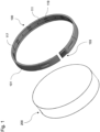
- Fig. 1 shows a view of a holding device 100 for a round dental blank 200.
- the round dental blank can be circular, cylindrical or oval Dental blank 200.
- the holding device is suitable for all shapes of dental blanks that can be enclosed by the ring element 101.
- the holding device 100 comprises an open, belt-shaped ring element 101 for laterally gripping the dental blank 200.
- the edge of the ring element 101 can be rounded at the top and bottom.
- the holding device 100 includes a closing element 103 for closing the ring element 101 in several positions.
- the holding device 100 is made of plastic, such as polyamide (PA12).
- the dental blank 200 is a circular disc-shaped blank, such as made of zirconium, from which dental objects can be milled out.
- the ring element 101 By closing the ring element 101 at different positions, it can be ensured that the ring element 101 is always tensioned around the dental blank 200 with sufficient pretension. For smaller dental blanks 200, the ring element 101 is closed at a narrower position. For larger dental blanks 200, the ring element 101 is closed at a further position.
- the ring element 101 includes an adhesive gap 111 along its length, into which a liquid adhesive is introduced.
- the adhesive additionally connects the holding device 100 to the dental blank 200.
- the adhesive gap 111 additionally includes tapered and projecting holding points 117, which rest on the side surface of the dental blank 200.
- a liquid polymer that hardens with atmospheric moisture can be used as an adhesive.
- a fastening gap 111 can also be provided, which increases the elasticity of the ring element 101 and serves to fasten the holding device 100.
- the adhesive gap or the fastening gap 111 Support feet 119, which are arranged at the same height as the outer walls of the ring element 101.
- the elongated support feet 119 provide optimized adhesion. As adhesive gap thinners, the support feet 119 increase the adhesive surface and create greater rigidity of the ring element 101. The support feet 119 allow immediate adhesion to be achieved as quickly as possible.
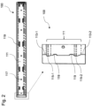
- Fig. 2 shows a cross-sectional view through the holding device 100.
- the adhesive gap 111 for receiving the adhesive runs between an upper circumferential edge 113-1 and a lower circumferential edge 113-2 of the ring element 101.
- the adhesive gap 111 has, for example, a depth of 0.2 mm and is in the center of the ring element 101 arranged.
- the surface of the adhesive gap 111 can be roughened so that the adhesive sticks better. This can be achieved by sandblasting the surface of an injection molded workpiece.
- An upper peripheral excess trough 115-1 extends adjacent an upper peripheral edge 113-1 and a lower peripheral excess trough 115-2 extends adjacent a lower peripheral edge 113-1.
- the excess troughs 115-1 and 115-2 absorb excess adhesive so that it cannot escape from the adhesive gap 111 to the outside.
- the excess trough for example, has a depth of 0.4 mm and therefore a level 0.2 mm lower than the adhesive gap 111.
- the ring element 101 preferably includes tapered holding points 117 in the middle of the adhesive gap 111.
- the holding points 117 prevent the holding device 100 from slipping until the adhesive has hardened.
- the Retaining points 117 are distributed along the adhesive gap 111 and have, for example, an overhang of 0.1 mm.
- the holding points 117 are pressed and deformed or penetrate into the dental blank 200. In this way, they are subjected to a preload.
- the holding points 117 prevent slipping during later processing steps, such as printing, labeling or packaging.
- Fig. 3 shows several views of a closing element 103. Surveys and depressions interlock.
- the ring element 101 has an opening with which the holding device 100 can be attached to the dental blank 200.
- the ring element 101 To close the ring element 101, it comprises a closing element 103 which is provided with an overlap at which the two ends of the ring element can be welded together.
- the overlap is formed by a tongue 105, which is arranged at one end of the ring element 101, and a recess 107 for inserting the tongue 105, which is arranged at another end of the ring element 101.
- the tongue 105 can be continuously pushed into the recess 107.
- the holder device 100 can be continuously closed in numerous positions and thus adapt to the diameter of the dental blank 200. Depending on the position, a different inner diameter of the holding device 100 is achieved.
- the ring element 101 can also be attached to the dental blank 200 by means of shrinkage, ie without adhesive.
- the holder device 100 can be fixed by gluing and/or shrinking.
- the overlap on the tongue 105 and the recess 107 has raised welding ribs 109.
- the elongated welding ribs extend in the insertion direction of the tongue 105 and the recess 107.
- the welding ribs as a possible closure geometry 109 create defined contact areas between the tongue 105 and the recess 109, on which the material can be melted specifically using an ultrasonic welding process in order to connect the two ends of the ring element 101 to one another.
- the closing element can also be closed using hot stamping or quick gluing.
- the overlap by the closing element 103 is designed so that dental blanks 200 with different diameters can be wrapped around.
- the overlap during welding is, for example, 4 to 6 mm.
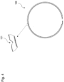
- Fig. 4 shows a view of a joint notch 121.
- the joint notch 121 is formed by a V-shaped recess in the ring element 101 and enables the ring element to be bent in a joint-like manner. This allows the ring element 101 to be opened and placed around the dental blank 200.
- the joint notch 121 enables a defined expansion of the ring element 101.
- the joint notch 121 is arranged opposite the closing element 103.
- Fig. 5 shows a cross-sectional view through the holding device 100.
- the holding device 100 includes a Edge protection element 123 for protecting or gripping an edge 125 of the dental blank 200.
- the angled or straight edge protection element 123 extends from the ring element 101.
- Fig. 6 shows a view of a closing device 300 for closing a closing element 103 with a tongue 105.
- the adhesive is applied radially to the dental blank 200 by means of an application device before the ring element 101 is attached.
- the dental blank 200 rotates and the adhesive is applied.
- the advantage is that the caliper does not come into contact with the user after the ring element 101 has been applied. Furthermore, no adhesive supply channels are necessary.
- the locking device 300 has a system for pressing the ring element 101.
- the system clamps the ring element 101 onto the dental blank 200 with a force.
- the locking device 300 can apply a defined force to the ring element 101 via a cylinder and a reinforcing spring.
- one end of the ring element 101 comprises a first clamping geometry 127-1 for engaging a first mandrel 129-1 and the other end of the ring element 101 includes a second clamping geometry 127-2 for engaging a second mandrel 129-2.
- the clamping geometries 127-1 and 127-2 are formed, for example, as recesses or depressions in the ring element ring element 101.
- the ring preload can be precisely adjusted using the clamping geometries 127-1 and 127-2.
- the clamping geometries 127-1 and 127-2 can be arranged in different configurations, such as square, rectangular, round, or oval, at a suitable point radially all around the ring element 101 or on the edges of the ring element 101. Thanks to the clamping geometries 127-1 and 127-2, a tool can be used to pull on the when closing Ring element 101 can be exerted so that it can be closed with a preload.
- the preloading can be done precisely by applying compressed air pressure to the cylinder of the preloading device.
- the measurement of the preload force can be carried out using a load cell.
- the preload of the ring element 101 can be applied to different degrees.
- the overlapping closing element 103 is closed using ultrasonic welding, hot stamping or quick-release adhesive.
- an ultrasonic welding head 131 is pressed onto the closing element 103. This heats and fuses the closing element 103. The welding is not visible from the outside. The adhesion of the weld can be achieved with simple welding parameters and is above the required adhesion. There is an overlap at the welding point so that the dental blank 200 cannot be seen from the front.
- All method steps can be implemented by devices that are suitable for carrying out the respective method step. All functions that are carried out by physical features can be a procedural step of a process.
Landscapes
- Engineering & Computer Science (AREA)
- Mechanical Engineering (AREA)
- Health & Medical Sciences (AREA)
- Oral & Maxillofacial Surgery (AREA)
- Dentistry (AREA)
- Epidemiology (AREA)
- Life Sciences & Earth Sciences (AREA)
- Animal Behavior & Ethology (AREA)
- General Health & Medical Sciences (AREA)
- Public Health (AREA)
- Veterinary Medicine (AREA)
- Dental Tools And Instruments Or Auxiliary Dental Instruments (AREA)
- Jigs For Machine Tools (AREA)
Abstract
Description
- Die vorliegende Erfindung betrifft eine Haltevorrichtung für einen runden Dentalrohling und ein Verfahren zum Einspannen eines runden Dentalrohlings.
- Dentalrohlinge zum Herstellen von Dentalobjekten in dentaltechnischen Herstellungsgeräten weisen oft fertigungsbedingte Toleranzen auf. Beispielsweise kann der Durchmesser von kreisförmigen oder runden Dentalrohlingen variieren. Werden diese in herkömmlichen Haltevorrichtungen angeordnet, weisen diese ein Spiel auf. Dies führt bei der Herstellung von Dentalobjekten, beispielsweise mithilfe eines Fräsverfahrens, zu Ungenauigkeiten. Zudem können beim Einspannen des Dentalrohlings Abplatzungen an der Umlaufkerbe entstehen, die Chipping genannt werden.
- Es ist die technische Aufgabe der vorliegenden Erfindung, eine Haltevorrichtung für einen runden Dentalrohling derart zu verbessern, dass Dentalrohlinge mit unterschiedlichen Fertigungstoleranzen spielfrei aufgenommen werden können.
- Diese technische Aufgabe wird durch Gegenstände nach den unabhängigen Ansprüchen gelöst. Technisch vorteilhafte Ausführungsformen sind Gegenstand der abhängigen Ansprüche, der Beschreibung und der Zeichnungen.
- Gemäß einem ersten Aspekt wird die technische Aufgabe durch eine Haltevorrichtung für einen runden Dentalrohling gelöst, mit einem offenen Ringelement zum seitlichen Umgreifen des Dentalrohlings; und einem Schließelement zum Schließen des Ringelements an mehreren Positionen. Durch die Haltevorrichtung wird der technische Vorteil erreicht, dass auch Dentalrohlinge mit unterschiedlichen Durchmessern sicher in der Haltevorrichtung befestigt werden können, da das Ringelement stets unter Spannung geschlossen werden kann. Bei einem größeren Umfang des Dentalrohlings wird das Schließelement in einer weiteren Position geschlossen und bei einem kleineren Umfang des Dentalrohlings wird das Schließelement in einer engeren Position geschlossen. Dadurch können auch Dentalrohlinge mit Fertigungstoleranzen spielfrei vorgespannt und befestigt werden. Die Haltevorrichtung kann sich den verschiedenen Durchmessern der Dentalrohlinge anpassen.
- In einer technisch vorteilhaften Ausführungsform der Haltevorrichtung umfasst das Schließelement eine Zunge und eine Aussparung zum Einschieben oder Einrasten der Zunge.
- Die Zunge kann Rastelemente aufweisen, die auf der Gegenseite des Ringelements in größere Rastgeometrien eingreifen. Mittels der größer dimensionierten Rastgeometrien können auch die Fertigungstoleranzen kompensiert werden.
- Dadurch wird beispielsweise der technische Vorteil erreicht, dass der Umfang des Ringelements kontinuierlich im Bereich der Länge der Zunge oder Tiefe der Aussparung verändert werden kann. Die Aussparung oder Zunge kann auch mit positiven oder negativen Rastgeometrien ausgebildet sein, die in entsprechende gegenüberliegende Rastgeometrien eingreifen. In einer weiteren technisch vorteilhaften Ausführungsform der Haltevorrichtung umfasst die Zunge oder die Aussparung ein oder mehrere Verschlussgeometrien. Die Verschlussgeometrien können beispielsweise Verschweißungsrippen umfassen. Dadurch wird beispielsweise der technische Vorteil erreicht, dass die Zunge mit der Aussparung wirksam verschweißt werden kann.
- In einer weiteren technisch vorteilhaften Ausführungsform der Haltevorrichtung umfasst das eine Ende des Ringelements eine erste Spanngeometrie zum Angreifen eines ersten Spanndorns und das andere Ende des Ringelements eine zweite Spanngeometrie zum Angreifen eines zweiten Spanndorns. Die Spanngeometrien können als Aussparungen gebildet sein, in die der jeweilige Spanndorn eingesetzt werden kann. Dadurch wird beispielsweise der technische Vorteil erreicht, dass das Ringelement mit einer hohen Spannung geschlossen werden und einer Vorspannung beaufschlagt werden kann.
- In einer weiteren technisch vorteilhaften Ausführungsform der Haltevorrichtung umfasst das Ringelement einen Klebespalt zum Einfügen eines Klebers oder einen Befestigungsspalt. Der Klebespalt oder der Befestigungsspalt kann zwischen einem oberen umlaufenden Rand und einem unteren umlaufenden Rand des Ringelements angeordnet sein. Der Kleber kann in dem Klebespalt im Vorhinein, während einem Spritzgießen der Haltevorrichtung angeordnet werden.
- Mittels einer Schrumpfung oder des Vorspannens des Ringelements können die Festhaltepunkte und/oder Aufliegefüße in spitzer Ausgestaltung in das Material eindringen und dadurch den Halt verbessern. Bei harten Dentalrohlingen können diese verformt oder gequetscht werden, ohne in das Material des Dentalrohlings einzudringen. Mittels den Festhaltepunkten und/oder den Aufliegefüßen kann die Befestigung der Haltevorrichtung verbessert werden. Dadurch wird beispielsweise der technische Vorteil erreicht, dass die Halterung des Dentalrohlings zusätzlich stabilisiert wird. Dies ist zudem bei Temperaturschwankungen vorteilhaft, die beim Transport in verschiedene Klimazonen entstehen können. Dadurch können die unterschiedlichen Temperaturausdehnungskoeffizienten der Materialen bei Temperaturschwankungen ausgeglichen werden können.
- In einer weiteren technisch vorteilhaften Ausführungsform der Haltevorrichtung umfasst der Klebespalt zumindest eine umlaufende Überschussmulde zum Aufnehmen des überschüssigen Klebers. Dadurch wird beispielsweise der technische Vorteil erreicht, dass der flüssige Kleber nicht aus dem Klebespalt herausquellen kann.
- In einer weiteren technisch vorteilhaften Ausführungsform der Haltevorrichtung umfasst der Klebespalt eine erste umlaufende Überschussmulde, die benachbart zu einem oberen umlaufenden Rand verläuft und eine zweite umlaufende Überschussmulde, die benachbart zu einem unteren umlaufenden Rand verläuft. Dadurch wird beispielsweise der technische Vorteil erreicht, dass vor jedem Rand eine Überschussmulde angeordnet ist, die ein Auslaufen von Kleber wirksam verhindert.
- In einer weiteren technisch vorteilhaften Ausführungsform der Haltevorrichtung umfasst der Klebespalt mehrere vorspringende Festhaltepunkte. Dadurch wird beispielsweise der technische Vorteil erreicht, dass sich eine vorläufige Befestigung des Dentalrohlings erreichen lässt, bevor der Kleber ausgehärtet ist.
- In einer weiteren technisch vorteilhaften Ausführungsform der Haltevorrichtung sind die Festhaltepunkte entlang des Klebespaltes verteilt und/oder in der Mitte des Klebespalts angeordnet sind. Dadurch wird beispielsweise der technische Vorteil erreicht, dass sich ein hoher Druck auf den Umfang des Dentalrohlings ausüben lässt, durch den sie die Fixierung des Dentalrohlings verbessert.
- In einer weiteren technisch vorteilhaften Ausführungsform der Haltevorrichtung umfasst der Klebespalt mehrere vorspringende Aufliegefüße. Dadurch wird beispielsweise der technische Vorteil erreicht, dass eine bessere Haftung erzielt wird. Als Klebespaltverdünnungen vergrößern die Aufliegefüße die Klebefläche und erzeugen eine größere Steifigkeit.
- In einer weiteren technisch vorteilhaften Ausführungsform der Haltevorrichtung sind die Aufliegefüße entlang des Klebespaltes verteilt und/oder in Paaren angeordnet. Dadurch wird beispielsweise der technische Vorteil erreicht, dass eine noch bessere Haftung erreicht wird.
- In einer weiteren technisch vorteilhaften Ausführungsform der Haltevorrichtung umfasst das Ringelement an seinem Außenumfang eine Gelenkkerbe. Dadurch wird beispielsweise der technische Vorteil erreicht, dass dieses aufgeweitet werden kann und auf einfache Weise um den Dentalrohling herum angeordnet werden kann. Zudem wird ein definiertes Aufweiten oder Öffnen ermöglicht.
- In einer weiteren technisch vorteilhaften Ausführungsform der Haltevorrichtung ist die Gelenkkerbe gegenüber von dem Schließelement angeordnet. Dadurch wird beispielsweise der technische Vorteil erreicht, dass das Ringelement weit geöffnet werden kann. Die Gelenkkerbe kann zudem eine Elastizität des Ringelements in Längsrichtung bewirken. In diesem Fall liegt das Ringelement stets am Dentalrohling an.
- In einer weiteren technisch vorteilhaften Ausführungsform der Haltevorrichtung umfasst das Ringelement zumindest ein Kantenschutzelement zum Umgreifen einer Kante des Dentalrohlings. Dadurch wird beispielsweise der technische Vorteil erreicht, dass eine Beschädigung der Kanten des Dentalrohlings verhindert werden kann.
- Gemäß einem zweiten Aspekt wird die technische Aufgabe durch ein Verfahren zum Einspannen eines runden Dentalrohlings mit einer Haltevorrichtung nach dem ersten Aspekt gelöst. Durch das Verfahren werden die gleichen technische Vorteile wie durch die Haltevorrichtung gelöst.
- Ausführungsbeispiele der Erfindung sind in den Zeichnungen dargestellt und werden im Folgenden näher beschrieben.
- Es zeigen:
- Fig. 1
- eine Ansicht einer Haltevorrichtung und eines Dentalrohlings;
- Fig. 2
- eine Querschnittsansicht durch die Haltevorrichtung;
- Fig. 3
- mehrere Ansichten eines Schließelements;
- Fig. 4
- eine Ansicht einer Gelenkkerbe;
- Fig. 5
- eine Querschnittsansicht durch die Haltevorrichtung; und
- Fig. 6
- eine Ansicht eines Schließgerätes zum Schließen eines Schließelements.
-
Fig. 1 zeigt eine Ansicht eine Haltevorrichtung 100 für einen runden Dentalrohling 200. Der runde Dentalrohling kann ein kreisscheibenförmiger, ein zylindrischer oder ein ovaler Dentalrohling 200 sein. Die Haltevorrichtung für alle Formen von Dentalrohlingen geeignet, die sich mittels des Ringelements 101 umschließen lassen. Die Haltevorrichtung 100 umfasst ein offenes, gürtelförmiges Ringelement 101 zum seitlichen Umgreifen des Dentalrohlings 200. Die Kante des Ringelements 101 kann unten und oben abgerundet sein. - Zudem umfasst die Haltevorrichtung 100 ein Schließelement 103 zum Schließen des Ringelements 101 an mehreren Positionen. Die Haltevorrichtung 100 ist aus Kunststoff gebildet, wie beispielsweise Polyamid (PA12). Der Dentalrohling 200 ist ein kreisscheibenförmiger Rohling wie beispielsweise aus Zirkon, aus dem Dentalobjekte herausgefräst werden können.
- Durch das Schließen des Ringelements 101 an unterschiedlichen Positionen kann sichergestellt werden, dass das Ringelement 101 stets mit einer ausreichenden Vorspannung um den Dentalrohling 200 gespannt ist. Bei kleineren Dentalrohlingen 200 wird das Ringelement 101 an einer engeren Position geschlossen. Bei größeren Dentalrohlingen 200 wird das Ringelement 101 an einer weiteren Position geschlossen.
- Das Ringelement 101 umfasst entlang seiner Länge einen Klebespalt 111, in den ein flüssiger Kleber eingebracht wird. Der Kleber verbindet die Haltevorrichtung 100 zusätzlich mit dem Dentalrohling 200. Der Klebepalt 111 umfasst zusätzlich spitz zulaufende und vorspringende Festhaltepunkte 117, die an der Seitenfläche des Dentalrohlings 200 anliegen. Als Kleber kann ein flüssiges Polymer verwendet werden, das mit Luftfeuchtigkeit aushärtet. Es kann auch ein Befestigungsspalt 111 vorgesehen sein, der die Elastizität des Ringelements 101 erhöht und zur Befestigung des Haltevorrichtung 100 dient. Des Weiteren umfasst der Klebespalt oder der Befestigungsspalt 111 Aufliegefüße 119, die auf gleicher Höhe wie die Außenwände des Ringelements 101 angeordnet sind.
- Durch die langestreckten Aufliegefüße 119 wird eine optimierte Haftung erhalten. Als Klebespaltverdünnungen vergrößern die Aufliegefüße 119 die Klebefläche und erzeugen eine größere Steifigkeit des Ringelements 101. Durch die Aufliegefüße 119 kann eine möglichst schnelle Soforthaftung erzielt werden.
-
Fig. 2 zeigt eine Querschnittsansicht durch die Haltevorrichtung 100. Der Klebespalt 111 zum Aufnehmen des Klebers verläuft zwischen einem oberen umlaufenden Rand 113-1 und einem unteren umlaufenden Rand 113-2 des Ringelements 101. Der Klebespalt 111 weist beispielsweise eine Tiefe von 0.2 mm auf und ist in der Mitte des Ringelements 101 angeordnet. Oberfläche des Klebespalts 111 kann aufgeraut sein, so dass der Kleber besser haften bleibt. Dies kann durch eine sandgestrahlte Oberfläche eines Spritzgusswerkstücks erreicht werden. - Eine obere umlaufende Überschussmulde 115-1 verläuft benachbart zu einem oberen umlaufenden Rand 113-1 und eine untere umlaufende Überschussmulde 115-2 verläuft benachbart zu einem unteren umlaufenden Rand 113-1. Die Überschussmulden 115-1 und 115-2 nehmen überschüssigen Kleber auf, so dass dieser nicht aus dem Klebespalt 111 nach außen dringen kann. Die Überschussmulde hat beispielsweise eine Tiefe von 0.4 mm und damit ein 0.2 mm niedrigeres Niveau als der Klebespalt 111.
- Das Ringelement 101 umfasst vorzugsweise spitz zulaufende Festhaltepunkte 117 in der Mitte des Klebespalts 111. Die Festhaltepunkte 117 verhindern ein Verrutschen der Haltevorrichtung 100 bis zur Aushärtung des Klebers. Die Festhaltepunkte 117 sind entlang des Klebespalts 111 verteilt und weisen beispielsweise einen Überstand von 0.1 mm. Die Festhaltepunkte 117 werden beim Anbringen des Ringelementes 101 an die Scheibe des Dentalrohlings 200 angepresst und verformt oder dringen in den Dentalrohling 200 ein. Auf diese Weise werden diese mit einer Vorspannung beaufschlagt. Die Festhaltepunkte 117 verhindern ein Verrutschen bei den späteren Verarbeitungsschritten, wie beispielsweise beim Bedrucken, Etikettieren oder Verpacken.
-
Fig. 3 zeigt mehrere Ansichten eines Schließelements 103. Erhebungen und Vertiefungen ineinandergreifen. Das Ringelement 101 weist eine Öffnung auf, mit der die Haltevorrichtung 100 an dem Dentalrohling 200 angebracht werden kann. - Zum Schließen des Ringelements 101 umfasst dieses ein Schließelement 103, das mit einer Überlappung versehen ist, an der die zwei Enden des Ringelementes zusammengeschweißt werden können. Die Überlappung ist durch eine Zunge 105 gebildet, die an einem Ende des Ringelements 101 angeordnet ist und eine Aussparung 107 zum Einschieben der Zunge 105, die an einem anderen Ende des Ringelements 101 angeordnet ist. Die Zunge 105 kann kontinuierlich in die Aussparung 107 geschoben werden. Auf diese Weise kann die Haltervorrichtung 100 kontinuierlich an zahlreichen Positionen geschlossen werden und sich so dem Durchmesser des Dentalrohlings 200 anpassen. Je nach Position wird dabei ein anderer Innendurchmesser der Haltevorrichtung 100 erreicht.
- Das Ringelement 101 kann neben einer Verklebung auch mittels einer Schrumpfung, d.h. ohne Kleber, an dem Dentalrohling 200 befestigt werden. Die Haltervorrichtung 100 kann mittels einer Verklebung und/oder Schrumpfung fixiert werden.
- Zur Verbesserung der Verschweißung verfügt die Überlappung an der Zunge 105 und der der Aussparung 107 über erhabene Verschweißungsrippen 109. Die länglichen Verschweißungsrippen erstrecken sich in Einsteckrichtung der Zunge 105 und der Aussparung 107. Die Verschweißungsrippen als mögliche Verschlussgeometrie 109 erzeugen definierte Kontaktbereiche zwischen Zunge 105 und Aussparung 109, an denen das Material gezielt mittels eines Ultraschallschweißverfahrens aufgeschmolzen werden kann, um die beiden Enden des Ringelements 101 miteinander zu verbinden. Das Schließelement kann auch mittels einem Heißprägen oder einem Schnellkleben geschlossen werden. Die Überlappung durch das Schließelement 103 ist so gestaltet, dass eine Umschlingung von Dentalrohlingen 200 mit unterschiedlichen Durchmessern möglich ist. Die Überlappung bei der Verschweißung beträgt beispielsweise 4 bis 6 mm.
- So kann sich bei kleinen Dentalrohlingen 200 ein Frontspalt an der Schweißseite von 1 mm und bei großen Dentalrohlingen 200 ein Frontspalt von 4 mm ergeben. Um eine Sichtbarkeit des Dentalrohlings 200 zu verhindern, können zwei zusätzliche Überlappungen an der Schweißstelle angebracht sein.
-
Fig. 4 zeigt eine Ansicht einer Gelenkkerbe 121. Die Gelenkkerbe 121 ist durch eine V-förmige Vertiefung im Ringelement 101 gebildet und ermöglicht ein gelenkartiges Knicken des Ringelementes. Dadurch kann das Ringelement 101 geöffnet werden und um den Dentalrohling 200 gelegt werden. Die Gelenkkerbe 121 ermöglicht ein definiertes Ausweiten des Ringelements 101. Die Gelenkkerbe 121 ist gegenüber von dem Schließelement 103 angeordnet. -
Fig. 5 zeigt eine Querschnittsansicht durch die Haltevorrichtung 100. Die Haltevorrichtung 100 umfasst ein Kantenschutzelement 123 zum Schützen oder Umgreifen einer Kante 125 des Dentalrohlings 200. Das gewinkelte oder gerade Kantenschutzelement 123 erstreckt sich vom Ringelement 101. -
Fig. 6 zeigt eine Ansicht eines Schließgerätes 300 zum Schließen eines Schließelements 103 mit einer Zunge 105. Der Kleber wird vor Anbringung des Ringelements 101 radial auf dem Dentalrohling 200 mittels einer Auftragsvorrichtung aufgebracht. Hierbei dreht sich der Dentalrohling 200 und der Kleber wird aufgetragen. In diesem Fall liegt der Vorteil darin, dass der Kelber nach Aufbringung des Ringelements 101 nicht mit dem Benutzer in Berührung kommt. Des Weiteren sind keine Klebezuführkanäle notwendig. - Das Schließgerät 300 verfügt über ein System zum Anpressen des Ringelementes 101. Durch das System wird das Ringelement 101 mit einer Kraft auf den Dentalrohling 200 gespannt. Das Schließgerät 300 kann über einen Zylinder und eine Verstärkungsfeder eine definierte Kraft an das Ringelement 101 anlegen. Zur Übertragung der Kraft umfasst das eine Ende des Ringelements 101 eine erste Spanngeometrie 127-1 zum Angreifen eines ersten Spanndorns 129-1 und das andere Ende des Ringelements 101 eine zweite Spanngeometrie 127-2 zum Angreifen eines zweiten Spanndorns 129-2. Die Spanngeometrien 127-1 und 127-2 sind beispielsweise als Aussparungen oder Vertiefungen in dem Ringelement Ringelement 101 gebildet. Durch die Spanngeometrien 127-1 und 127-2 kann die Ringvorspannung präzise eingestellt werden. Die Spanngeometrien 127-1 und 127-2 können in unterschiedlichen Ausgestaltungen, wie beispielsweise eckig, rechteckig, rund, oder oval, an geeigneter Stelle radial umlaufend am Ringelement 101 oder an den Kanten des Ringelements 101 angeordnet sein. Durch die Spanngeometrien 127-1 und 127-2 kann mittels eines Werkzeugs Beim Schließen ein Zug auf das Ringelement 101 ausgeübt werden, so dass dieses mit einer Vorspannung geschlossen werden kann.
- Die Vorspannung kann genau durch das Anlegen eines Pressluftdrucks an den Zylinder der Vorspanneinrichtung erfolgen. Die Messung der Vorspannkraft kann mittels einer Kraftmessdose durchgeführt werden. Durch das Variieren eines Pressluftdrucks kann die Vorspannung des Ringelements 101 unterschiedlich stark beaufschlagt werden.
- Ist das Ringelement 101 gespannt, wird das überlappende Schließelement 103 mittels einer Ultraschallschweißung, Heißprägung oder Schnellkleber geschlossen. Hierzu wird auf das Schließelement 103 ein Ultraschallschweißkopf 131 gedrückt. Dieser erhitz und verschmilzt das Schließelement 103. Die Verschweißung ist von außen nicht ersichtlich. Die Haftung der Verschweißung ist mit einfachen Schweißparametern zu realisieren und liegt über der benötigten Haftung. Bei der Schweißstelle erfolgt eine Überlappung, so dass der Dentalrohling 200 von vorne nicht zu sehen ist.
- Alle in Verbindung mit einzelnen Ausführungsformen der Erfindung erläuterten und gezeigten Merkmale können in unterschiedlicher Kombination in dem erfindungsgemäßen Gegenstand vorgesehen sein, um gleichzeitig deren vorteilhafte Wirkungen zu realisieren.
- Alle Verfahrensschritte können durch Vorrichtungen implementiert werden, die zum Ausführen des jeweiligen Verfahrensschrittes geeignet sind. Alle Funktionen, die von gegenständlichen Merkmalen ausgeführt werden, können ein Verfahrensschritt eines Verfahrens sein.
- Der Schutzbereich der vorliegenden Erfindung ist durch die Ansprüche gegeben und wird durch die in der Beschreibung erläuterten oder den Figuren gezeigten Merkmale nicht beschränkt.
-
- 100
- Haltevorrichtung
- 101
- Ringelement
- 103
- Schließelement
- 105
- Zunge
- 107
- Aussparung
- 109
- Verschlussgeometrie
- 111
- Klebespalt/Befestigungsspalt
- 113
- Rand
- 115
- Überschussmulde
- 117
- Festhaltepunkt
- 119
- Aufliegefuß
- 121
- Gelenkkerbe
- 123
- Kantenschutzelement
- 125
- Kante
- 127
- Spanngeometrie
- 129
- Spanndorn
- 131
- Ultraschallschweißkopf
- 200
- Dentalrohling
Claims (15)
- Haltevorrichtung (100) für einen runden Dentalrohling (200), mit:- einem offenen Ringelement (101) zum seitlichen Umgreifen des Dentalrohlings (200); und- einem Schließelement (103) zum Schließen des Ringelements (101) an mehreren Positionen.
- Haltevorrichtung (100) nach Anspruch 1, wobei das Schließelement (103) durch eine Zunge (105) und eine Aussparung (107) zum Einschieben oder Einrasten der Zunge (105) umfasst.
- Haltevorrichtung (100) nach Anspruch 2, wobei die Zunge (105) oder die Aussparung (107) ein oder mehrere Verschlussgeometrien (109) umfasst.
- Haltevorrichtung (100) nach einem der vorangehenden Ansprüche, wobei das eine Ende des Ringelements (101) eine erste Spanngeometrie (127-1) zum Angreifen eines ersten Spanndorns (129-1) und das andere Ende des Ringelements (101) eine zweite Spanngeometrie (127-2) zum Angreifen eines zweiten Spanndorns (129-2) umfasst.
- Haltevorrichtung (100) nach einem der vorangehenden Ansprüche, wobei das Ringelement (101) einen Klebespalt (111) zum Einfügen eines Klebers umfasst.
- Haltevorrichtung (100) nach Anspruch 5, wobei der Klebespalt (111) zumindest eine umlaufende Überschussmulde (115-1, 115-2) zum Aufnehmen des überschüssigen Klebers umfasst.
- Haltevorrichtung (100) nach Anspruch 6, wobei der Klebespalt (111) eine erste umlaufende Überschussmulde (115-1) umfasst, die benachbart zu einem oberen umlaufenden Rand (113-1) verläuft und eine zweite umlaufende Überschussmulde (115-2) umfasst, die benachbart zu einem unteren umlaufenden Rand (113-1) verläuft.
- Haltevorrichtung (100) nach einem der Ansprüche 5 bis 7, wobei der Klebespalt (111) mehrere vorspringende Festhaltepunkte (117) umfasst.
- Haltevorrichtung (100) nach Anspruch 8, wobei die Festhaltepunkte (117) entlang des Klebespaltes (111) verteilt sind und/oder in der Mitte des Klebespalts (111) angeordnet sind.
- Haltevorrichtung (100) nach einem der Ansprüche 4 bis 9, wobei der Klebespalt (111) mehrere vorspringende Aufliegefüße (119) umfasst.
- Haltevorrichtung (100) nach Anspruch 10, wobei die Aufliegefüße (119) entlang des Klebespaltes (111) verteilt sind und/oder in Paaren angeordnet sind.
- Haltevorrichtung (100) nach einem der vorangehenden Ansprüche, wobei das Ringelement (101) an seinem Außenumfang eine Gelenkkerbe (121) umfasst.
- Haltevorrichtung (100) nach Anspruch 12, wobei die Gelenkkerbe (121) gegenüber von dem Schließelement (103) angeordnet ist.
- Haltevorrichtung (100) nach einem der vorangehenden Ansprüche, wobei das Ringelement (101) zumindest ein Kantenschutzelement (123) zum Umgreifen einer Kante (125) des Dentalrohlings (200) umfasst.
- Verfahren zum Einspannen eines runden Dentalrohlings (200) mit einer Haltevorrichtung (100) nach einem der Ansprüche 1 bis 14.
Priority Applications (8)
| Application Number | Priority Date | Filing Date | Title |
|---|---|---|---|
| EP24211110.2A EP4480444A3 (de) | 2022-03-08 | 2022-03-08 | Haltevorrichtung für einen dentalrohling |
| EP22160824.3A EP4241732B1 (de) | 2022-03-08 | 2022-03-08 | Haltevorrichtung für einen dentalrohling |
| ES22160824T ES3006507T3 (en) | 2022-03-08 | 2022-03-08 | Holding device for a dental blank |
| CA3191615A CA3191615A1 (en) | 2022-03-08 | 2023-03-01 | Holding device for a dental blank |
| JP2023033267A JP7678013B2 (ja) | 2022-03-08 | 2023-03-04 | 歯科用ブランク用の把持装置 |
| KR1020230029994A KR20230132390A (ko) | 2022-03-08 | 2023-03-07 | 치과용 블랭크를 위한 유지 장치 |
| US18/179,857 US12151332B2 (en) | 2022-03-08 | 2023-03-07 | Dental blank and a holding device |
| CN202310220385.1A CN116728121A (zh) | 2022-03-08 | 2023-03-08 | 牙科坯料的保持装置及夹持圆形牙科坯料的方法 |
Applications Claiming Priority (1)
| Application Number | Priority Date | Filing Date | Title |
|---|---|---|---|
| EP22160824.3A EP4241732B1 (de) | 2022-03-08 | 2022-03-08 | Haltevorrichtung für einen dentalrohling |
Related Child Applications (1)
| Application Number | Title | Priority Date | Filing Date |
|---|---|---|---|
| EP24211110.2A Division EP4480444A3 (de) | 2022-03-08 | 2022-03-08 | Haltevorrichtung für einen dentalrohling |
Publications (2)
| Publication Number | Publication Date |
|---|---|
| EP4241732A1 true EP4241732A1 (de) | 2023-09-13 |
| EP4241732B1 EP4241732B1 (de) | 2024-11-27 |
Family
ID=80684140
Family Applications (2)
| Application Number | Title | Priority Date | Filing Date |
|---|---|---|---|
| EP22160824.3A Active EP4241732B1 (de) | 2022-03-08 | 2022-03-08 | Haltevorrichtung für einen dentalrohling |
| EP24211110.2A Pending EP4480444A3 (de) | 2022-03-08 | 2022-03-08 | Haltevorrichtung für einen dentalrohling |
Family Applications After (1)
| Application Number | Title | Priority Date | Filing Date |
|---|---|---|---|
| EP24211110.2A Pending EP4480444A3 (de) | 2022-03-08 | 2022-03-08 | Haltevorrichtung für einen dentalrohling |
Country Status (7)
| Country | Link |
|---|---|
| US (1) | US12151332B2 (de) |
| EP (2) | EP4241732B1 (de) |
| JP (1) | JP7678013B2 (de) |
| KR (1) | KR20230132390A (de) |
| CN (1) | CN116728121A (de) |
| CA (1) | CA3191615A1 (de) |
| ES (1) | ES3006507T3 (de) |
Families Citing this family (1)
| Publication number | Priority date | Publication date | Assignee | Title |
|---|---|---|---|---|
| US12458475B1 (en) * | 2024-09-05 | 2025-11-04 | King Saud University | Dental system including a ceramic block holding assembly and a ceramic block coupleable with the ceramic block holding assembly, and a method of using the dental system |
Citations (3)
| Publication number | Priority date | Publication date | Assignee | Title |
|---|---|---|---|---|
| EP3284438A1 (de) * | 2016-08-17 | 2018-02-21 | Shofu Inc. | Fräsrohling für dentales cad/cam mit ausgeschnittenem abschnitt zur positionierung |
| EP3372192A1 (de) * | 2017-03-10 | 2018-09-12 | Johannes Petrus Michael Grobbee | Zahnrohlingpositionierungsvorrichtung |
| EP3995107A1 (de) * | 2020-11-06 | 2022-05-11 | Ivoclar Vivadent AG | Dentalronden-halter und anordnung aus halter und dentalronde |
Family Cites Families (19)
| Publication number | Priority date | Publication date | Assignee | Title |
|---|---|---|---|---|
| JPS4924857U (de) * | 1972-06-09 | 1974-03-02 | ||
| JPH0625609U (ja) * | 1992-08-31 | 1994-04-08 | 加藤発条株式会社 | ハーネスクリップ |
| US5390395A (en) * | 1993-12-09 | 1995-02-21 | Hans Oetiker Ag Maschioen- Und Apparatefabrik | Earless, stepless clamp structure |
| DE9407491U1 (de) * | 1994-05-05 | 1995-02-23 | Hintersehr, Josef, 64347 Griesheim | Halteelement für Werkstücke, die in eine Haltevorrichtung eingespannt werden, um eine exakte Plazierung des Rohmaterials zu ermöglichen |
| WO2002035130A2 (en) * | 2000-10-27 | 2002-05-02 | Fluidmaster, Inc. | Bayonet quick coupler |
| US7698014B2 (en) | 2006-01-20 | 2010-04-13 | 3M Innovative Properties Company | Local enforcement of accuracy in fabricated models |
| US7568567B2 (en) * | 2006-08-02 | 2009-08-04 | Gm Global Technology Operations, Inc. | Snap-ring with additional loop |
| CN103003041A (zh) * | 2010-04-29 | 2013-03-27 | 牙科实验室铣床用品有限责任公司 | 用于由坯料生产产品的方法、系统和装置 |
| DE102015100666A1 (de) * | 2015-01-19 | 2016-07-21 | Dentsply International Inc. | Halterung für einen Rohling |
| DE102015204174A1 (de) * | 2015-03-09 | 2016-09-15 | Precis Glashütte GmbH | Haltevorrichtung für Dentalrohlinge |
| KR102464512B1 (ko) * | 2015-03-19 | 2022-11-07 | 쿠라레 노리타케 덴탈 가부시키가이샤 | 피가공 유닛 및 그 제조 방법 |
| CN107427346B (zh) * | 2015-03-19 | 2021-09-24 | 可乐丽则武齿科株式会社 | 被加工单元 |
| US10080406B2 (en) * | 2016-02-12 | 2018-09-25 | Aro-Sac, Inc. | Adjustable bracelet |
| US11858083B2 (en) * | 2017-03-09 | 2024-01-02 | Global Dental Science, LLC | Dental blank positioning device |
| CN208784961U (zh) * | 2017-12-05 | 2019-04-26 | 朱连芳 | 使用于制造义齿的氧化锆盘的伸缩框件 |
| DE202017006526U1 (de) * | 2017-12-20 | 2018-06-26 | General Camdent Gmbh | Werkstückhalter für Dentalrohlinge bestehend aus zwei mit Stüzvorsprüngen versehenen radial geschlitzten Ringen. |
| FR3085730B1 (fr) * | 2018-09-06 | 2021-01-15 | Sogefi Suspensions | Bague pour corps cylindrique |
| CN211276678U (zh) * | 2020-01-08 | 2020-08-18 | 漯河医学高等专科学校第二附属医院 | 一种适用于义齿雕铣机的饼料夹持装置 |
| EP3995106B1 (de) | 2020-11-06 | 2024-10-02 | Ivoclar Vivadent AG | Dentalronden-haltering |
-
2022
- 2022-03-08 ES ES22160824T patent/ES3006507T3/es active Active
- 2022-03-08 EP EP22160824.3A patent/EP4241732B1/de active Active
- 2022-03-08 EP EP24211110.2A patent/EP4480444A3/de active Pending
-
2023
- 2023-03-01 CA CA3191615A patent/CA3191615A1/en active Pending
- 2023-03-04 JP JP2023033267A patent/JP7678013B2/ja active Active
- 2023-03-07 US US18/179,857 patent/US12151332B2/en active Active
- 2023-03-07 KR KR1020230029994A patent/KR20230132390A/ko active Pending
- 2023-03-08 CN CN202310220385.1A patent/CN116728121A/zh active Pending
Patent Citations (3)
| Publication number | Priority date | Publication date | Assignee | Title |
|---|---|---|---|---|
| EP3284438A1 (de) * | 2016-08-17 | 2018-02-21 | Shofu Inc. | Fräsrohling für dentales cad/cam mit ausgeschnittenem abschnitt zur positionierung |
| EP3372192A1 (de) * | 2017-03-10 | 2018-09-12 | Johannes Petrus Michael Grobbee | Zahnrohlingpositionierungsvorrichtung |
| EP3995107A1 (de) * | 2020-11-06 | 2022-05-11 | Ivoclar Vivadent AG | Dentalronden-halter und anordnung aus halter und dentalronde |
Also Published As
| Publication number | Publication date |
|---|---|
| JP7678013B2 (ja) | 2025-05-15 |
| US20230286090A1 (en) | 2023-09-14 |
| KR20230132390A (ko) | 2023-09-15 |
| US12151332B2 (en) | 2024-11-26 |
| EP4241732B1 (de) | 2024-11-27 |
| JP2023131133A (ja) | 2023-09-21 |
| CN116728121A (zh) | 2023-09-12 |
| CA3191615A1 (en) | 2023-09-08 |
| EP4480444A2 (de) | 2024-12-25 |
| EP4480444A3 (de) | 2025-01-22 |
| ES3006507T3 (en) | 2025-03-18 |
Similar Documents
| Publication | Publication Date | Title |
|---|---|---|
| EP2573410B1 (de) | Haltemittel mit einem axialen Durchgang zur Aufnahme eines Formatteiles | |
| EP0613757A1 (de) | Werkstück-Spannvorrichtung | |
| DE3915732C2 (de) | Verbindungsanordnung | |
| DE202012101508U1 (de) | Abstützvorrichtung | |
| DE1475035B2 (de) | Befestigungsvorrichtung | |
| DE102019110701A1 (de) | Halteelement zum halten eines zu befestigenden bauteils und haltesystem mit einem solchen | |
| EP4241732B1 (de) | Haltevorrichtung für einen dentalrohling | |
| EP4112949A1 (de) | Rastbolzen, elektronikmodul und herstellverfahren | |
| DE2708538A1 (de) | Verbindung zwischen den kettengliedern einer gleiskette | |
| DE19832797C1 (de) | Fixiervorrichtung für nebeneinander angeordnete Knochenplatten und Anlegeinstrument dafür | |
| EP2101948B1 (de) | Vorrichtung und verfahren zum positionieren eines werkzeugs oder werkstücks auf eine werkzeugmaschine | |
| DE102021109063A1 (de) | Spannbare elektrische Heizvorrichtung | |
| DE4023583A1 (de) | Positioniervorrichtung | |
| DE2804962B2 (de) | Vorrichtung zum Befestigen einer biegsamen Dachhaut auf ihrer Unterlage | |
| WO2013123935A1 (de) | Bauteilverbinder zum verbinden von zylindrischen bauteilen | |
| EP1724495A1 (de) | Zahnriementrieb und Verfahren zur Herstellung einer Riemenscheibe für einen Zahnriementrieb | |
| DE102009001406A1 (de) | Vorrichtung zum Befestigen eines konzentrischen Teils auf einem Zapfen eines Zylinders einer Druckmaschine | |
| DE939730C (de) | Gleichlaufeinrichtung fuer Geschwindigkeits-Wechselgetriebe, insbesondere fuer Kraftfahrzeuge | |
| DE4119447C1 (de) | Osteosyntheseimplantat | |
| DE10224117A1 (de) | Kunststoffdübel | |
| DE4238614C1 (de) | Bolzenförmiges Paßelement zum Fixieren, Zentrieren und/oder Positionieren von Paßbohrungen aufweisenden Teilen | |
| DE2460100A1 (de) | Loesbare drehsicherung fuer ein mit einem umfangsprofil versehenes teil | |
| DE102019123132A1 (de) | Düseneinsatz für eine Spritzgießdüse eines Spritzgießwerkzeugs mit einem Halteelement, Spritzgießdüse mit einem Halteelement und Spritzgießwerkzeug | |
| EP4261446B1 (de) | Befestigungsvorrichtung, anordnung mit einer befestigungsvorrichtung und verfahren zum herstellen einer befestigungsvorrichtung | |
| EP1727445B1 (de) | Vorrichtung zum halten eines zahnbürstenkopfes |
Legal Events
| Date | Code | Title | Description |
|---|---|---|---|
| PUAI | Public reference made under article 153(3) epc to a published international application that has entered the european phase |
Free format text: ORIGINAL CODE: 0009012 |
|
| STAA | Information on the status of an ep patent application or granted ep patent |
Free format text: STATUS: THE APPLICATION HAS BEEN PUBLISHED |
|
| AK | Designated contracting states |
Kind code of ref document: A1 Designated state(s): AL AT BE BG CH CY CZ DE DK EE ES FI FR GB GR HR HU IE IS IT LI LT LU LV MC MK MT NL NO PL PT RO RS SE SI SK SM TR |
|
| STAA | Information on the status of an ep patent application or granted ep patent |
Free format text: STATUS: REQUEST FOR EXAMINATION WAS MADE |
|
| 17P | Request for examination filed |
Effective date: 20240206 |
|
| RBV | Designated contracting states (corrected) |
Designated state(s): AL AT BE BG CH CY CZ DE DK EE ES FI FR GB GR HR HU IE IS IT LI LT LU LV MC MK MT NL NO PL PT RO RS SE SI SK SM TR |
|
| GRAP | Despatch of communication of intention to grant a patent |
Free format text: ORIGINAL CODE: EPIDOSNIGR1 |
|
| STAA | Information on the status of an ep patent application or granted ep patent |
Free format text: STATUS: GRANT OF PATENT IS INTENDED |
|
| INTG | Intention to grant announced |
Effective date: 20240617 |
|
| P01 | Opt-out of the competence of the unified patent court (upc) registered |
Free format text: CASE NUMBER: APP_48925/2024 Effective date: 20240827 |
|
| GRAS | Grant fee paid |
Free format text: ORIGINAL CODE: EPIDOSNIGR3 |
|
| GRAA | (expected) grant |
Free format text: ORIGINAL CODE: 0009210 |
|
| STAA | Information on the status of an ep patent application or granted ep patent |
Free format text: STATUS: THE PATENT HAS BEEN GRANTED |
|
| AK | Designated contracting states |
Kind code of ref document: B1 Designated state(s): AL AT BE BG CH CY CZ DE DK EE ES FI FR GB GR HR HU IE IS IT LI LT LU LV MC MK MT NL NO PL PT RO RS SE SI SK SM TR |
|
| REG | Reference to a national code |
Ref country code: GB Ref legal event code: FG4D Free format text: NOT ENGLISH |
|
| REG | Reference to a national code |
Ref country code: CH Ref legal event code: EP |
|
| REG | Reference to a national code |
Ref country code: IE Ref legal event code: FG4D Free format text: LANGUAGE OF EP DOCUMENT: GERMAN |
|
| REG | Reference to a national code |
Ref country code: DE Ref legal event code: R096 Ref document number: 502022002201 Country of ref document: DE |
|
| REG | Reference to a national code |
Ref country code: ES Ref legal event code: FG2A Ref document number: 3006507 Country of ref document: ES Kind code of ref document: T3 Effective date: 20250318 |
|
| REG | Reference to a national code |
Ref country code: LT Ref legal event code: MG9D |
|
| REG | Reference to a national code |
Ref country code: NL Ref legal event code: MP Effective date: 20241127 |
|
| PG25 | Lapsed in a contracting state [announced via postgrant information from national office to epo] |
Ref country code: HR Free format text: LAPSE BECAUSE OF FAILURE TO SUBMIT A TRANSLATION OF THE DESCRIPTION OR TO PAY THE FEE WITHIN THE PRESCRIBED TIME-LIMIT Effective date: 20241127 Ref country code: IS Free format text: LAPSE BECAUSE OF FAILURE TO SUBMIT A TRANSLATION OF THE DESCRIPTION OR TO PAY THE FEE WITHIN THE PRESCRIBED TIME-LIMIT Effective date: 20250327 Ref country code: PT Free format text: LAPSE BECAUSE OF FAILURE TO SUBMIT A TRANSLATION OF THE DESCRIPTION OR TO PAY THE FEE WITHIN THE PRESCRIBED TIME-LIMIT Effective date: 20250327 |
|
| PG25 | Lapsed in a contracting state [announced via postgrant information from national office to epo] |
Ref country code: NL Free format text: LAPSE BECAUSE OF FAILURE TO SUBMIT A TRANSLATION OF THE DESCRIPTION OR TO PAY THE FEE WITHIN THE PRESCRIBED TIME-LIMIT Effective date: 20241127 Ref country code: FI Free format text: LAPSE BECAUSE OF FAILURE TO SUBMIT A TRANSLATION OF THE DESCRIPTION OR TO PAY THE FEE WITHIN THE PRESCRIBED TIME-LIMIT Effective date: 20241127 |
|
| PG25 | Lapsed in a contracting state [announced via postgrant information from national office to epo] |
Ref country code: BG Free format text: LAPSE BECAUSE OF FAILURE TO SUBMIT A TRANSLATION OF THE DESCRIPTION OR TO PAY THE FEE WITHIN THE PRESCRIBED TIME-LIMIT Effective date: 20241127 |
|
| PG25 | Lapsed in a contracting state [announced via postgrant information from national office to epo] |
Ref country code: NO Free format text: LAPSE BECAUSE OF FAILURE TO SUBMIT A TRANSLATION OF THE DESCRIPTION OR TO PAY THE FEE WITHIN THE PRESCRIBED TIME-LIMIT Effective date: 20250227 |
|
| PG25 | Lapsed in a contracting state [announced via postgrant information from national office to epo] |
Ref country code: LV Free format text: LAPSE BECAUSE OF FAILURE TO SUBMIT A TRANSLATION OF THE DESCRIPTION OR TO PAY THE FEE WITHIN THE PRESCRIBED TIME-LIMIT Effective date: 20241127 Ref country code: GR Free format text: LAPSE BECAUSE OF FAILURE TO SUBMIT A TRANSLATION OF THE DESCRIPTION OR TO PAY THE FEE WITHIN THE PRESCRIBED TIME-LIMIT Effective date: 20250228 |
|
| PG25 | Lapsed in a contracting state [announced via postgrant information from national office to epo] |
Ref country code: PL Free format text: LAPSE BECAUSE OF FAILURE TO SUBMIT A TRANSLATION OF THE DESCRIPTION OR TO PAY THE FEE WITHIN THE PRESCRIBED TIME-LIMIT Effective date: 20241127 |
|
| PG25 | Lapsed in a contracting state [announced via postgrant information from national office to epo] |
Ref country code: RS Free format text: LAPSE BECAUSE OF FAILURE TO SUBMIT A TRANSLATION OF THE DESCRIPTION OR TO PAY THE FEE WITHIN THE PRESCRIBED TIME-LIMIT Effective date: 20250227 |
|
| PG25 | Lapsed in a contracting state [announced via postgrant information from national office to epo] |
Ref country code: SM Free format text: LAPSE BECAUSE OF FAILURE TO SUBMIT A TRANSLATION OF THE DESCRIPTION OR TO PAY THE FEE WITHIN THE PRESCRIBED TIME-LIMIT Effective date: 20241127 |
|
| PG25 | Lapsed in a contracting state [announced via postgrant information from national office to epo] |
Ref country code: DK Free format text: LAPSE BECAUSE OF FAILURE TO SUBMIT A TRANSLATION OF THE DESCRIPTION OR TO PAY THE FEE WITHIN THE PRESCRIBED TIME-LIMIT Effective date: 20241127 |
|
| PGFP | Annual fee paid to national office [announced via postgrant information from national office to epo] |
Ref country code: ES Payment date: 20250403 Year of fee payment: 4 |
|
| PGFP | Annual fee paid to national office [announced via postgrant information from national office to epo] |
Ref country code: IT Payment date: 20250331 Year of fee payment: 4 |
|
| PG25 | Lapsed in a contracting state [announced via postgrant information from national office to epo] |
Ref country code: EE Free format text: LAPSE BECAUSE OF FAILURE TO SUBMIT A TRANSLATION OF THE DESCRIPTION OR TO PAY THE FEE WITHIN THE PRESCRIBED TIME-LIMIT Effective date: 20241127 |
|
| PGFP | Annual fee paid to national office [announced via postgrant information from national office to epo] |
Ref country code: CH Payment date: 20250429 Year of fee payment: 4 |
|
| PG25 | Lapsed in a contracting state [announced via postgrant information from national office to epo] |
Ref country code: RO Free format text: LAPSE BECAUSE OF FAILURE TO SUBMIT A TRANSLATION OF THE DESCRIPTION OR TO PAY THE FEE WITHIN THE PRESCRIBED TIME-LIMIT Effective date: 20241127 |
|
| PG25 | Lapsed in a contracting state [announced via postgrant information from national office to epo] |
Ref country code: SK Free format text: LAPSE BECAUSE OF FAILURE TO SUBMIT A TRANSLATION OF THE DESCRIPTION OR TO PAY THE FEE WITHIN THE PRESCRIBED TIME-LIMIT Effective date: 20241127 |
|
| PG25 | Lapsed in a contracting state [announced via postgrant information from national office to epo] |
Ref country code: CZ Free format text: LAPSE BECAUSE OF FAILURE TO SUBMIT A TRANSLATION OF THE DESCRIPTION OR TO PAY THE FEE WITHIN THE PRESCRIBED TIME-LIMIT Effective date: 20241127 |
|
| REG | Reference to a national code |
Ref country code: DE Ref legal event code: R097 Ref document number: 502022002201 Country of ref document: DE |
|
| PG25 | Lapsed in a contracting state [announced via postgrant information from national office to epo] |
Ref country code: SE Free format text: LAPSE BECAUSE OF FAILURE TO SUBMIT A TRANSLATION OF THE DESCRIPTION OR TO PAY THE FEE WITHIN THE PRESCRIBED TIME-LIMIT Effective date: 20241127 |
|
| PLBE | No opposition filed within time limit |
Free format text: ORIGINAL CODE: 0009261 |
|
| STAA | Information on the status of an ep patent application or granted ep patent |
Free format text: STATUS: NO OPPOSITION FILED WITHIN TIME LIMIT |
|
| PG25 | Lapsed in a contracting state [announced via postgrant information from national office to epo] |
Ref country code: MC Free format text: LAPSE BECAUSE OF FAILURE TO SUBMIT A TRANSLATION OF THE DESCRIPTION OR TO PAY THE FEE WITHIN THE PRESCRIBED TIME-LIMIT Effective date: 20241127 |
|
| 26N | No opposition filed |
Effective date: 20250828 |
|
| PG25 | Lapsed in a contracting state [announced via postgrant information from national office to epo] |
Ref country code: LU Free format text: LAPSE BECAUSE OF NON-PAYMENT OF DUE FEES Effective date: 20250308 |
|
| REG | Reference to a national code |
Ref country code: BE Ref legal event code: MM Effective date: 20250331 |
|
| PG25 | Lapsed in a contracting state [announced via postgrant information from national office to epo] |
Ref country code: BE Free format text: LAPSE BECAUSE OF NON-PAYMENT OF DUE FEES Effective date: 20250331 |
|
| PG25 | Lapsed in a contracting state [announced via postgrant information from national office to epo] |
Ref country code: IE Free format text: LAPSE BECAUSE OF NON-PAYMENT OF DUE FEES Effective date: 20250308 |
|
| PGFP | Annual fee paid to national office [announced via postgrant information from national office to epo] |
Ref country code: GB Payment date: 20260324 Year of fee payment: 5 |
|
| PGFP | Annual fee paid to national office [announced via postgrant information from national office to epo] |
Ref country code: DE Payment date: 20260320 Year of fee payment: 5 |
|
| PGFP | Annual fee paid to national office [announced via postgrant information from national office to epo] |
Ref country code: AT Payment date: 20260301 Year of fee payment: 5 |
|
| PGFP | Annual fee paid to national office [announced via postgrant information from national office to epo] |
Ref country code: FR Payment date: 20260327 Year of fee payment: 5 |
|
| PGFP | Annual fee paid to national office [announced via postgrant information from national office to epo] |
Ref country code: TR Payment date: 20260227 Year of fee payment: 5 |