EP4241034B1 - Dispositif de régulation thermique, notamment de refroidissement pour véhicule automobile - Google Patents
Dispositif de régulation thermique, notamment de refroidissement pour véhicule automobile Download PDFInfo
- Publication number
- EP4241034B1 EP4241034B1 EP21787466.8A EP21787466A EP4241034B1 EP 4241034 B1 EP4241034 B1 EP 4241034B1 EP 21787466 A EP21787466 A EP 21787466A EP 4241034 B1 EP4241034 B1 EP 4241034B1
- Authority
- EP
- European Patent Office
- Prior art keywords
- channels
- fluid
- notably
- reinforcing element
- diverting chamber
- Prior art date
- Legal status (The legal status is an assumption and is not a legal conclusion. Google has not performed a legal analysis and makes no representation as to the accuracy of the status listed.)
- Active
Links
Images
Classifications
-
- F—MECHANICAL ENGINEERING; LIGHTING; HEATING; WEAPONS; BLASTING
- F28—HEAT EXCHANGE IN GENERAL
- F28F—DETAILS OF HEAT-EXCHANGE AND HEAT-TRANSFER APPARATUS, OF GENERAL APPLICATION
- F28F3/00—Plate-like or laminated elements; Assemblies of plate-like or laminated elements
- F28F3/12—Elements constructed in the shape of a hollow panel, e.g. with channels
-
- F—MECHANICAL ENGINEERING; LIGHTING; HEATING; WEAPONS; BLASTING
- F28—HEAT EXCHANGE IN GENERAL
- F28D—HEAT-EXCHANGE APPARATUS, NOT PROVIDED FOR IN ANOTHER SUBCLASS, IN WHICH THE HEAT-EXCHANGE MEDIA DO NOT COME INTO DIRECT CONTACT
- F28D21/00—Heat-exchange apparatus not covered by any of the groups F28D1/00 - F28D20/00
-
- F—MECHANICAL ENGINEERING; LIGHTING; HEATING; WEAPONS; BLASTING
- F28—HEAT EXCHANGE IN GENERAL
- F28F—DETAILS OF HEAT-EXCHANGE AND HEAT-TRANSFER APPARATUS, OF GENERAL APPLICATION
- F28F3/00—Plate-like or laminated elements; Assemblies of plate-like or laminated elements
- F28F3/02—Elements or assemblies thereof with means for increasing heat-transfer area, e.g. with fins, with recesses, with corrugations
- F28F3/04—Elements or assemblies thereof with means for increasing heat-transfer area, e.g. with fins, with recesses, with corrugations the means being integral with the element
- F28F3/042—Elements or assemblies thereof with means for increasing heat-transfer area, e.g. with fins, with recesses, with corrugations the means being integral with the element in the form of local deformations of the element
- F28F3/046—Elements or assemblies thereof with means for increasing heat-transfer area, e.g. with fins, with recesses, with corrugations the means being integral with the element in the form of local deformations of the element the deformations being linear, e.g. corrugations
-
- F—MECHANICAL ENGINEERING; LIGHTING; HEATING; WEAPONS; BLASTING
- F28—HEAT EXCHANGE IN GENERAL
- F28F—DETAILS OF HEAT-EXCHANGE AND HEAT-TRANSFER APPARATUS, OF GENERAL APPLICATION
- F28F9/00—Casings; Header boxes; Auxiliary supports for elements; Auxiliary members within casings
- F28F9/02—Header boxes; End plates
- F28F9/0246—Arrangements for connecting header boxes with flow lines
- F28F9/0251—Massive connectors, e.g. blocks; Plate-like connectors
- F28F9/0253—Massive connectors, e.g. blocks; Plate-like connectors with multiple channels, e.g. with combined inflow and outflow channels
-
- H—ELECTRICITY
- H01—ELECTRIC ELEMENTS
- H01M—PROCESSES OR MEANS, e.g. BATTERIES, FOR THE DIRECT CONVERSION OF CHEMICAL ENERGY INTO ELECTRICAL ENERGY
- H01M10/00—Secondary cells; Manufacture thereof
- H01M10/60—Heating or cooling; Temperature control
- H01M10/61—Types of temperature control
- H01M10/613—Cooling or keeping cold
-
- H—ELECTRICITY
- H01—ELECTRIC ELEMENTS
- H01M—PROCESSES OR MEANS, e.g. BATTERIES, FOR THE DIRECT CONVERSION OF CHEMICAL ENERGY INTO ELECTRICAL ENERGY
- H01M10/00—Secondary cells; Manufacture thereof
- H01M10/60—Heating or cooling; Temperature control
- H01M10/65—Means for temperature control structurally associated with the cells
- H01M10/655—Solid structures for heat exchange or heat conduction
- H01M10/6556—Solid parts with flow channel passages or pipes for heat exchange
-
- H—ELECTRICITY
- H01—ELECTRIC ELEMENTS
- H01M—PROCESSES OR MEANS, e.g. BATTERIES, FOR THE DIRECT CONVERSION OF CHEMICAL ENERGY INTO ELECTRICAL ENERGY
- H01M10/00—Secondary cells; Manufacture thereof
- H01M10/60—Heating or cooling; Temperature control
- H01M10/65—Means for temperature control structurally associated with the cells
- H01M10/656—Means for temperature control structurally associated with the cells characterised by the type of heat-exchange fluid
- H01M10/6569—Fluids undergoing a liquid-gas phase change or transition, e.g. evaporation or condensation
-
- F—MECHANICAL ENGINEERING; LIGHTING; HEATING; WEAPONS; BLASTING
- F28—HEAT EXCHANGE IN GENERAL
- F28D—HEAT-EXCHANGE APPARATUS, NOT PROVIDED FOR IN ANOTHER SUBCLASS, IN WHICH THE HEAT-EXCHANGE MEDIA DO NOT COME INTO DIRECT CONTACT
- F28D1/00—Heat-exchange apparatus having stationary conduit assemblies for one heat-exchange medium only, the media being in contact with different sides of the conduit wall, in which the other heat-exchange medium is a large body of fluid, e.g. domestic or motor car radiators
- F28D1/02—Heat-exchange apparatus having stationary conduit assemblies for one heat-exchange medium only, the media being in contact with different sides of the conduit wall, in which the other heat-exchange medium is a large body of fluid, e.g. domestic or motor car radiators with heat-exchange conduits immersed in the body of fluid
- F28D1/03—Heat-exchange apparatus having stationary conduit assemblies for one heat-exchange medium only, the media being in contact with different sides of the conduit wall, in which the other heat-exchange medium is a large body of fluid, e.g. domestic or motor car radiators with heat-exchange conduits immersed in the body of fluid with plate-like or laminated conduits
- F28D1/0366—Heat-exchange apparatus having stationary conduit assemblies for one heat-exchange medium only, the media being in contact with different sides of the conduit wall, in which the other heat-exchange medium is a large body of fluid, e.g. domestic or motor car radiators with heat-exchange conduits immersed in the body of fluid with plate-like or laminated conduits the conduits being formed by spaced plates with inserted elements
- F28D1/0375—Heat-exchange apparatus having stationary conduit assemblies for one heat-exchange medium only, the media being in contact with different sides of the conduit wall, in which the other heat-exchange medium is a large body of fluid, e.g. domestic or motor car radiators with heat-exchange conduits immersed in the body of fluid with plate-like or laminated conduits the conduits being formed by spaced plates with inserted elements the plates having lateral openings therein for circulation of the heat-exchange medium from one conduit to another
-
- F—MECHANICAL ENGINEERING; LIGHTING; HEATING; WEAPONS; BLASTING
- F28—HEAT EXCHANGE IN GENERAL
- F28D—HEAT-EXCHANGE APPARATUS, NOT PROVIDED FOR IN ANOTHER SUBCLASS, IN WHICH THE HEAT-EXCHANGE MEDIA DO NOT COME INTO DIRECT CONTACT
- F28D1/00—Heat-exchange apparatus having stationary conduit assemblies for one heat-exchange medium only, the media being in contact with different sides of the conduit wall, in which the other heat-exchange medium is a large body of fluid, e.g. domestic or motor car radiators
- F28D1/02—Heat-exchange apparatus having stationary conduit assemblies for one heat-exchange medium only, the media being in contact with different sides of the conduit wall, in which the other heat-exchange medium is a large body of fluid, e.g. domestic or motor car radiators with heat-exchange conduits immersed in the body of fluid
- F28D1/03—Heat-exchange apparatus having stationary conduit assemblies for one heat-exchange medium only, the media being in contact with different sides of the conduit wall, in which the other heat-exchange medium is a large body of fluid, e.g. domestic or motor car radiators with heat-exchange conduits immersed in the body of fluid with plate-like or laminated conduits
- F28D1/0366—Heat-exchange apparatus having stationary conduit assemblies for one heat-exchange medium only, the media being in contact with different sides of the conduit wall, in which the other heat-exchange medium is a large body of fluid, e.g. domestic or motor car radiators with heat-exchange conduits immersed in the body of fluid with plate-like or laminated conduits the conduits being formed by spaced plates with inserted elements
- F28D1/0383—Heat-exchange apparatus having stationary conduit assemblies for one heat-exchange medium only, the media being in contact with different sides of the conduit wall, in which the other heat-exchange medium is a large body of fluid, e.g. domestic or motor car radiators with heat-exchange conduits immersed in the body of fluid with plate-like or laminated conduits the conduits being formed by spaced plates with inserted elements with U-flow or serpentine-flow inside the conduits
-
- F—MECHANICAL ENGINEERING; LIGHTING; HEATING; WEAPONS; BLASTING
- F28—HEAT EXCHANGE IN GENERAL
- F28D—HEAT-EXCHANGE APPARATUS, NOT PROVIDED FOR IN ANOTHER SUBCLASS, IN WHICH THE HEAT-EXCHANGE MEDIA DO NOT COME INTO DIRECT CONTACT
- F28D21/00—Heat-exchange apparatus not covered by any of the groups F28D1/00 - F28D20/00
- F28D2021/0019—Other heat exchangers for particular applications; Heat exchange systems not otherwise provided for
- F28D2021/0028—Other heat exchangers for particular applications; Heat exchange systems not otherwise provided for for cooling heat generating elements, e.g. for cooling electronic components or electric devices
- F28D2021/0029—Heat sinks
-
- F—MECHANICAL ENGINEERING; LIGHTING; HEATING; WEAPONS; BLASTING
- F28—HEAT EXCHANGE IN GENERAL
- F28F—DETAILS OF HEAT-EXCHANGE AND HEAT-TRANSFER APPARATUS, OF GENERAL APPLICATION
- F28F2210/00—Heat exchange conduits
- F28F2210/10—Particular layout, e.g. for uniform temperature distribution
-
- F—MECHANICAL ENGINEERING; LIGHTING; HEATING; WEAPONS; BLASTING
- F28—HEAT EXCHANGE IN GENERAL
- F28F—DETAILS OF HEAT-EXCHANGE AND HEAT-TRANSFER APPARATUS, OF GENERAL APPLICATION
- F28F2225/00—Reinforcing means
- F28F2225/04—Reinforcing means for conduits
-
- Y—GENERAL TAGGING OF NEW TECHNOLOGICAL DEVELOPMENTS; GENERAL TAGGING OF CROSS-SECTIONAL TECHNOLOGIES SPANNING OVER SEVERAL SECTIONS OF THE IPC; TECHNICAL SUBJECTS COVERED BY FORMER USPC CROSS-REFERENCE ART COLLECTIONS [XRACs] AND DIGESTS
- Y02—TECHNOLOGIES OR APPLICATIONS FOR MITIGATION OR ADAPTATION AGAINST CLIMATE CHANGE
- Y02E—REDUCTION OF GREENHOUSE GAS [GHG] EMISSIONS, RELATED TO ENERGY GENERATION, TRANSMISSION OR DISTRIBUTION
- Y02E60/00—Enabling technologies; Technologies with a potential or indirect contribution to GHG emissions mitigation
- Y02E60/10—Energy storage using batteries
Definitions
- the present invention relates to a thermal regulation device, in particular a cooling device, in particular for an electrical component likely to release heat during its operation, in particular a device for cooling at least one battery or battery cells of a motor vehicle.
- Cooling devices comprise cooling plates through which a coolant circulates.
- the cooling plates are installed, as far as possible without gaps, on the outside of the batteries for the purpose of dissipating heat or heating the battery.
- Cooling devices are known in which the cooling plate consists of two plate parts that are normally attached directly to each other.
- the first plate part is preferably flat
- the second plate part is preferably a pressed or deformed metal sheet that has meandering depressions. Said depressions are closed by the flat plate part that is attached to the pressed plate part, so that coolant ducts are formed.
- the patent EP 2 828 922 B1 describes such a device.
- the document FROM 10 2019 118356 A1 describes a device according to the preamble of claim 1.
- the invention aims to improve this type of device.
- the invention thus proposes a thermal regulation device, in particular a cooling device, for an electrical component likely to release heat during its operation, in particular for an energy storage module.
- this device comprising an upper plate and a lower plate assembled with the upper plate to form together a plurality of circulation channels for a heat transfer fluid, in particular a refrigerant fluid, in particular a fluid chosen from the following refrigerant fluids R134a, R1234yf or R744, device in which at least some of the channels open into at least one turning chamber by means of which the fluid can perform a turn, device in which at least one of the turning chamber and the channels comprises a mechanical reinforcement element formed on a wall of this turning chamber or of one of the channels, this reinforcement element being arranged to improve the mechanical strength of the chamber and/or the channel against potential deformations under the action of high pressure.
- the reinforcing element extends over the entire height of the turning chamber and the channels.
- the turning chamber and the channels each have a length measured along a direction of flow of the fluid, and the reinforcing element extends over only a part of the length respectively of the turning chamber or of the channel, in particular less than half of this length, or less than a quarter or a tenth of this length.
- the reinforcing element is relatively small compared to the turning chamber or channels as a whole.
- a plurality of reinforcing elements are provided along the turning chamber and/or one of the channels, this plurality of reinforcing elements being for example spaced from each other regularly.
- these reinforcing elements formed on the turning chamber are all identical.
- the reinforcing element has a rounded profile when viewed in a direction perpendicular to the plates, this rounded profile having a concavity directed towards the outside of the turning chamber or the associated channel.
- the concavity has a radius of curvature, in particular of a value less than 5 mm, in particular less than 2 mm.
- two neighboring channels connect on the turning chamber in connecting sections such that an inter-channel space is present on the turning chamber between the two connecting sections and the reinforcing element is located in this inter-channel space, in particular in the middle of this inter-channel space.
- the reinforcing elements are arranged, with regular spacing between them, along a line running along the turning chamber.
- the passage section of the fluid turning chamber is increased on either side of each reinforcing element.
- two neighboring fluid channels connect to the turning chamber, and the reinforcing element which is formed on a side wall of the turning chamber, opposite these two fluid channels, is arranged so as to be able to place an imaginary inscribed circle adjacent to the two neighboring channels and to the opposing reinforcing element, this inscribed circle having a diameter in particular less than 15 mm.
- the reinforcing element(s) are formed by stamping.
- the reinforcing element is placed in a junction zone of a channel with another channel or with a turning chamber, this reinforcing element being in particular opposite this channel.
- reinforcing elements are arranged along a straight line, in particular at equal distances from each other.
- the reinforcing elements make it possible to have larger fluid passage sections while ensuring good mechanical resistance to deformation.
- This increase in the refrigerant passage section is accompanied by a reduction in the pressure drop caused.
- the gain in passage section can be approximately +40% compared to a conventional design, without reinforcing elements.
- the invention also allows an improvement in the shape coefficient.
- the turning chamber may be arranged to allow a reversal of the fluid flow, or to allow fluid collection at the fluid inlet or outlet.
- the turning chamber may be referred to as a fluid inlet or outlet collection chamber.
- the invention also relates to a system comprising an electrical component capable of releasing heat during its operation, in particular for an electrical energy storage module, and a cooling device described above, arranged to cool the component, this component or battery being in thermal contact with the upper plate of the cooling device.
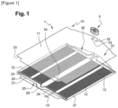
- a system 1 comprising a set of battery cells 2 to be cooled, for example arranged in two or more rows, and a cooling device 10 arranged to cool the cells 2, which are in thermal contact with an upper plate of the cooling device 10, as explained below.
- the thermal regulation device 10 comprises an upper plate 11, a lower plate 12 assembled with the upper plate 11 to together form a plurality of circulation channels 13 for a heat transfer fluid, in particular a refrigerant, in particular a fluid chosen from the following refrigerants R134a, R1234yf or R744.
- the channels 13 are grouped in groups 14 of channels, the channels of a group extending substantially parallel to each other with a predetermined spacing between neighboring channels called intra-group spacing 15.
- the channels 13 each have a cross-section of between 1 mm2 and 15 mm2, being for example locally approximately 11 mm2 in each channel.
- the channels 13 extend substantially over the entire length of the plates.
- the plates are made of aluminum.
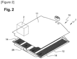
- the cooling device comprises a turning chamber 20 arranged to conduct the fluid exiting from one of the groups 14 of channels to one of the other groups of channels.
- the turning chamber 20 is formed by the upper 11 and lower 12 plates, for example made of aluminum.
- the lower plate 12 comprises a stamped area 21 arranged to participate in the formation of the turning chamber 20.
- the stamped area 21 is closed with the other of the plates 11 which is flat to form the turning chamber 20.
- the turning chamber 20 extends over one side 23 of the plates.
- the cooling device comprises a refrigerant fluid inlet zone 30 for the channels, this inlet zone being formed between the two plates 11 and 12.
- This fluid inlet zone 30 is arranged to supply all the fluid circulation channels 13 which open onto the turning chamber 20, namely the channels in which the fluid flows towards the turning chamber.
- This inlet zone 30 is common to the groups 14 of channels.
- the cooling device comprises a refrigerant fluid outlet zone 31 for the channels, this outlet zone being formed between the two plates 11 and 12.
- This fluid outlet zone 31 is arranged to conduct the fluid exiting from all the fluid circulation channels 13 which come from the turning chamber.
- This outlet zone 31 is common to both groups of channels.
- the inlet 30 and 31 and outlet zones are adjacent to an inlet orifice 32, respectively an outlet orifice 33.
- the inlet orifices 32 and outlet orifices 33 are connected to a tubing connection block 6.
- the lower plate 2 comprises areas 37 of rounded cross-section, in particular stamped areas, to form the channels 13 with the upper plate.
- the inlet 30 and outlet 31 areas comprise stamped areas of the lower plate 12.
- the heat transfer fluid can be chosen from refrigerant fluids called R134a, R1234yf or R744.
- the battery cells comprise, for example, a plurality of lithium-ion (Li-ion) batteries for use in a hybrid vehicle.
- the plurality of battery cells are Li-ion batteries for use in a battery electric vehicle.
- the turning chamber 20 and/or the inlet zone 30 and/or the outlet zone 31 comprise, where appropriate, reinforcing elements to reinforce the mechanical strength in these zones which are potentially of larger cross-section.
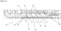
- Channels 13 open into a turning chamber 20 through which the fluid can perform a turn.
- the arrows 28 show the direction of flow of the fluid in the channels 13 and the turning chamber 20.
- the turning chamber 20 comprises mechanical reinforcement elements 27 formed on a wall of this turning chamber 20, each reinforcement element 27 being arranged to improve the mechanical resistance of the chamber against potential deformations under the action of high pressure.
- Each reinforcing element 27 extends over the entire height of the turning chamber 20.
- the turning chamber 20 and the channels 13 each have a length measured along a direction of flow of the fluid, and each reinforcing element 27 extends over only a part of the length of the turning chamber 20, here less than 1/5 or 1/8 or 1/10 of the total length of the associated turning chamber 20.
- the reinforcing elements 27 are provided along the turning chamber 20, this plurality of reinforcing elements being spaced from each other in a regular manner.
- These reinforcing elements 27 formed on the turning chamber 20 are all identical, of the same shape and the same dimensions.
- Reinforcing elements of different dimensions and/or sizes could, as a variant, be provided.
- Each reinforcing element 27 has a rounded profile when viewed in a direction perpendicular to the plates, this rounded profile having a concavity 29 directed towards the outside of the associated turning chamber 20.
- the concavity 29 has a radius of curvature, in particular of a value less than 5 mm, in particular less than 2 mm.
- the radius of curvature is that of the dotted circle on the Figure 3 , with a value of 1.1 mm.
- Two neighboring channels 13 connect to the turning chamber 20 in connecting sections 18 so that an inter-channel space 19 is present on the turning chamber 20 between the two connecting sections 18 and the reinforcing element 27 is located in this inter-channel space, here in the middle of this inter-channel space.
- the reinforcing elements 27 are arranged, with regular spacing between them, along a line 36 running along the turning chamber 20.
- the reinforcing elements 27 are formed by stamping on the corresponding plate.
- the reinforcing elements 27 allow for larger fluid passage sections while ensuring good mechanical resistance to deformation. This increase in the refrigerant passage section is accompanied by a reduction in the resulting pressure drop.
- the gain in passage section can be approximately +40% compared to a conventional design without reinforcing elements.
- Two neighboring fluid channels connect to the turning chamber, and the reinforcing element 27 which is formed on a side wall of the turning chamber, opposite these two fluid channels, is arranged so as to be able to place an imaginary circle 26 inscribed adjacent to the two neighboring channels and to the reinforcing element opposite, this inscribed circle 26 having a diameter less than 15 mm.
- passage section 25 of the fluid turning chamber 20 is increased on either side of each reinforcing element 27.
- the turning chamber 20 may be arranged to allow a reversal of the fluid flow, or to allow fluid collection at the fluid inlet or outlet. In the latter case, the turning chamber may be referred to as a fluid inlet or outlet collection chamber.
- one or more reinforcing elements 27 may be formed on at least one of the channels 13, in particular on a non-linear portion of this channel.
Landscapes
- Engineering & Computer Science (AREA)
- General Engineering & Computer Science (AREA)
- Physics & Mathematics (AREA)
- Thermal Sciences (AREA)
- Mechanical Engineering (AREA)
- Chemical & Material Sciences (AREA)
- Chemical Kinetics & Catalysis (AREA)
- Electrochemistry (AREA)
- General Chemical & Material Sciences (AREA)
- Manufacturing & Machinery (AREA)
- Secondary Cells (AREA)
- Cooling Or The Like Of Electrical Apparatus (AREA)
- Cooling, Air Intake And Gas Exhaust, And Fuel Tank Arrangements In Propulsion Units (AREA)
Description
- La présente invention concerne un dispositif de régulation thermique, notamment de refroidissement, notamment pour composant électrique susceptible de dégager de la chaleur lors de son fonctionnement, notamment un dispositif de refroidissement d'au moins une batterie ou cellules de batterie de véhicule automobile.
- Les batteries de véhicules, en particulier pour véhicules électriques ou véhicules hybrides, doivent autant que possible être maintenues à température souhaitée, raison pour laquelle on utilise des dispositifs dits de refroidissement pour batteries de véhicules. Ces dispositifs de refroidissement comprennent des plaques de refroidissement à travers lesquelles circule un liquide de refroidissement. Les plaques de refroidissement sont installées, autant que possible sans espace, sur le côté extérieur des batteries dans le but de dissiper la chaleur ou bien de chauffer la batterie. On connaît des dispositifs de refroidissement dans lesquels la plaque de refroidissement est composée de deux parties de plaque qui sont normalement fixées directement l'une à l'autre. Ici, la première partie de plaque est de préférence plane, et la seconde partie de plaque est de préférence une feuille de métal emboutie ou déformée qui présente des dépressions en méandres. Lesdites dépressions sont fermées par la partie de plaque plane qui est fixée à la partie de plaque emboutie, de sorte que des conduits de réfrigérant sont formés. Le brevet
EP 2 828 922 B1 décrit un tel dispositif. Le documentDE 10 2019 118356 A1 décrit un dispositif selon le préambule de la revendication 1. - L'invention vise à améliorer ce type de dispositif.
- L'invention propose ainsi un dispositif de régulation thermique, notamment de refroidissement, pour composant électrique susceptible de dégager de la chaleur lors de son fonctionnement, notamment pour un module de stockage d'énergie électrique, ce dispositif comportant une plaque supérieure et une plaque inférieure assemblée avec la plaque supérieure pour former ensemble une pluralité de canaux de circulation pour un fluide caloporteur, notamment un fluide réfrigérant, notamment un fluide choisi parmi les fluides réfrigérants suivants R134a, R1234yf ou R744, dispositif dans lequel au moins certains des canaux débouchent dans au moins une chambre de virage grâce à laquelle le fluide peut accomplir un virage, dispositif dans lequel l'un au moins de la chambre de virage et des canaux comporte un élément de renfort mécanique formé sur une paroi de cette chambre de virage ou de l'un des canaux, cet élément de renfort étant agencé pour améliorer la tenue mécanique de la chambre et/ou du canal contre de potentielles déformations sous l'action d'une pression élevée.
- Dans ce type de dispositif, il y a des concentrations de contraintes dans les zones où le fluide doit effectuer des virages, retournements ou ramifications, par exemple non linéaires, notamment dans les zones de distribution, de collecte ou de retournement de l'écoulement du fluide. Pour éviter la déformation dans ces zones, nous avons recours à des formes particulières, de préférence obtenues par emboutissage, que sont le ou les éléments de renfort selon l'invention.
- Selon un aspect de l'invention, l'élément de renfort s'étend sur toute la hauteur de la chambre de virage et des canaux.
- Selon un aspect de l'invention, la chambre de virage et les canaux présentent chacun une longueur mesurée suivant un sens d'écoulement du fluide, et l'élément de renfort s'étend sur une partie seulement de la longueur respectivement de la chambre de virage ou du canal, notamment moins de la moitié de cette longueur, ou moins d'un quart ou d'un dixième de cette longueur.
- Autrement dit, l'élément de renfort est relativement petit par rapport à la chambre de virage ou des canaux dans leur ensemble.
- Selon un aspect de l'invention, une pluralité d'éléments de renfort sont prévus le long de la chambre de virage et/ou de l'un des canaux, cette pluralité d'éléments de renfort étant par exemple espacés les uns des autres de manière régulière.
- Selon un aspect de l'invention, ces éléments de renfort formés sur la chambre de virage sont tous identiques.
- Selon un aspect de l'invention, l'élément de renfort présente un profil arrondi lorsqu'il est observé dans une direction perpendiculaire aux plaques, ce profil arrondi présentant une concavité dirigée vers l'extérieur de la chambre de virage ou du canal associé.
- Selon un aspect de l'invention, la concavité présente un rayon de courbure, notamment de valeur inférieure à 5 mm, notamment inférieure à 2 mm.
- Selon un aspect de l'invention, deux canaux voisins se raccordent sur la chambre de virage en des sections de raccord de sorte qu'un espace inter-canaux soit présent sur la chambre de virage entre les deux sections de raccord et l'élément de renfort est situé dans cet espace inter-canaux, notamment au milieu de cet espace inter-canaux.
- Selon un aspect de l'invention, les éléments de renforts sont disposés, avec un espacement régulier entre eux, le long d'une ligne longeant la chambre de virage.
- Selon un aspect de l'invention, la section de passage de la chambre de virage de fluide est augmentée de part et d'autre de chaque élément de renfort.
- Selon un aspect de l'invention, deux canaux de fluide voisins se raccordent à la chambre de virage, et l'élément de renfort qui est formé sur une paroi latérale de la chambre de virage, en vis-à-vis de ces deux canaux de fluide, est disposé de sorte à pouvoir placer un cercle imaginaire inscrit adjacent aux deux canaux voisins et à l'élément de renfort en vis-à-vis, ce cercle inscrit ayant un diamètre notamment inférieur à 15 mm.
- Selon l'invention, le ou les éléments de renfort sont formés par emboutissage.
- De préférence l'élément de renfort est placé dans une zone de jonction d'un canal avec un autre canal ou avec une chambre de virage, cet élément de renfort étant notamment en vis-à-vis de ce canal.
- Notamment lorsque u nombre N canaux consécutifs se raccorde à une chambre de virage, il est prévu un nombre M éléments de renfort consécutifs, avec M=N ou M inférieur à N.
- Selon un aspect de l'invention, des éléments de renfort sont disposés suivant une ligne droite, notamment à égale distance les uns des autres.
- Selon un aspect de l'invention, les éléments de renfort permettent d'avoir des sections de passage de fluide plus grandes tout en assurant une bonne tenue mécanique à la déformation. Cette augmentation de la section de passage du fluide réfrigérant s'accompagne d'une diminution de la perte de charge occasionnée. Le gain de section de passage peut être d'environ +40% par rapport à un design classique, sans élément de renfort.
- L'invention permet également une amélioration du coefficient de forme.
- Selon un aspect de l'invention, la chambre de virage peut être agencée pour permettre un retournement de l'écoulement de fluide, ou de pour permettre une collecte de fluide en entrée ou en sortie de fluide. Dans ce dernier cas, la chambre de virage peut être appelée chambre de collecte d'entrée ou de sortie de fluide.
- L'invention a encore pour objet un système comportant un composant électrique susceptible de dégager de la chaleur lors de son fonctionnement, notamment pour un module de stockage d'énergie électrique, et un dispositif de refroidissement décrit ci-dessus, agencé pour refroidir le composant, ce composant ou batterie étant en contact thermique avec la plaque supérieure du dispositif de refroidissement.
- D'autres caractéristiques et avantages de l'invention apparaitront plus clairement à la lecture de la description suivante, donnée à titre d'exemple illustratif et non limitatif, et des dessins annexés parmi lesquels :
- la [
Figure 1 ] illustre, schématiquement et partiellement, un dispositif selon de refroidissement ; - la [
Figure 2 ] illustre, schématiquement et partiellement, le dispositif de la [Figure 1 ] selon une vue différente, - la [
Figure 3 ] illustre, schématiquement et partiellement, un dispositif selon un autre exemple de l'invention, avec des détails sur une partie des plaques. - On a représenté sur la [
Figure 1 ] et sur la [Figure 2 ] un système 1 comportant un ensemble de cellules de batterie 2 à refroidir, par exemple rangées suivant deux rangées ou plus, et un dispositif de refroidissement 10 agencé pour refroidir les cellules 2, qui sont en contact thermique avec une plaque supérieure du dispositif de refroidissement 10, comme expliqué plus bas. - Le dispositif de régulation thermique 10 comporte une plaque supérieure 11, une plaque inférieure 12 assemblée avec la plaque supérieure 11 pour former ensemble une pluralité de canaux 13 de circulation pour un fluide caloporteur, notamment un fluide réfrigérant, notamment un fluide choisi parmi les fluides réfrigérants suivants R134a, R1234yf ou R744. Les canaux 13 sont regroupés par groupes 14 de canaux, les canaux d'un groupe s'étendant sensiblement parallèlement les uns aux autres avec un espacement prédéterminé entre canaux voisins appelé espacement intra-groupe 15. Les canaux 13 présentent chacun une section transversale comprise entre 1 mm2 et 15 mm2, étant par exemple localement d'environ 11 mm2 dans chaque canal. Les canaux 13 s'étendent sensiblement sur toute la longueur des plaques.
- Les plaques sont réalisées en aluminium.
- Le dispositif de refroidissement comporte une chambre de virage 20 agencée pour conduire le fluide sortant de l'un des groupes 14 de canaux vers l'un des autres groupes de canaux. La chambre de virage 20 est formée par les plaques supérieure 11 et inférieure 12, par exemple en aluminium. La plaque inferieure 12 comporte une zone emboutie 21 agencée pour participer à la formation de la chambre de virage 20. La zone emboutie 21 est fermée avec l'autre des plaques 11 qui est plane pour former la chambre de virage 20. La chambre de virage 20 s'étend sur un côté 23 des plaques.
- Le dispositif de refroidissement comporte une zone d'entrée 30 de fluide réfrigérant des canaux, cette zone d'entrée étant formée entre les deux plaques 11 et 12. Cette zone d'entrée 30 de fluide est agencée pour alimenter tous les canaux 13 de circulation de fluide qui débouchent sur la chambre de virage 20, à savoir les canaux dans lesquels le fluide s'écoule vers la chambre de virage. Cette zone d'entrée 30 est commune aux groupes 14 de canaux. Le dispositif de refroidissement comporte une zone de sortie 31 de fluide réfrigérant des canaux, cette zone de sortie étant formée entre les deux plaques 11 et 12. Cette zone de sortie 31 de fluide est agencée pour conduire le fluide sortant de tous les canaux 13 de circulation de fluide qui proviennent de la chambre de virage. Cette zone de sortie 31 est commune aux deux groupes de canaux. Les zones d'entrée 30 et 31 et de sortie sont adjacentes à un orifice d'entrée 32, respectivement de sortie 33. Les orifices d'entrée 32 et de sortie 33 sont reliés à un bloc de raccord 6 de tubulures.
- La plaque inférieure 2 comporte des zones 37 de section transversale arrondie, notamment des zones embouties, pour former avec la plaque supérieure les canaux 13. Les zones d'entrée 30 et de sortie 31 comportent des zones embouties de la plaque inferieure 12.
- Préférentiellement le fluide caloporteur peut être choisi parmi les fluides réfrigérants d'appellation R134a, R1234yf ou R744.
- Les cellules de batterie comprennent par exemple une pluralité de batteries au lithium-ion (Li-ion) pour une utilisation dans un véhicule hybride. Dans un autre mode de réalisation, la pluralité de cellules de batterie sont des batteries Li-ion pour une utilisation dans un véhicule électrique à batterie. La chambre de virage 20 et/ou la zone d'entrée 30 et/ou la zone de sortie 31 comportent, le cas échéant, des éléments de renfort pour renforcer la tenue mécanique dans ces zones qui sont potentiellement de plus forte section.
- On a représenté sur la [
Figure 3 ] un détail d'un dispositif selon un exemple de réalisation de l'invention, qui reprend la plupart des éléments de l'exemple décrit précédemment. - Il sera ici davantage décrit une chambre de virage et les canaux qui s'y raccordent.
- Des canaux 13 débouchent dans une chambre de virage 20 grâce à laquelle le fluide peut accomplir un virage.
- Les flèches 28 matérialisent le sens de l'écoulement du fluide dans les canaux 13 et la chambre de virage 20.
- La chambre de virage 20 comporte des éléments de renfort mécanique 27 formés sur une paroi de cette chambre de virage 20, chaque élément de renfort 27 étant agencé pour améliorer la tenue mécanique de la chambre contre de potentielles déformations sous l'action d'une pression élevée.
- Chaque élément de renfort 27 s'étend sur toute la hauteur de la chambre de virage 20.
- La chambre de virage 20 et les canaux 13 présentent chacun une longueur mesurée suivant un sens d'écoulement du fluide, et chaque élément de renfort 27 s'étend sur une partie seulement de la longueur de la chambre de virage 20, ici moins de 1/5 ou 1/8 ou 1/10 de la longueur totale de la chambre de virage 20 associée.
- Les éléments de renfort 27 sont prévus le long de la chambre de virage 20, cette pluralité d'éléments de renfort étant espacés les uns des autres de manière régulière.
- Ces éléments de renfort 27 formés sur la chambre de virage 20 sont tous identiques, de même forme et de mêmes dimensions.
- Des éléments de renfort de dimensions et/ou dimensions différents pourraient, en variante, être prévus.
- Chaque élément de renfort 27 présente un profil arrondi lorsqu'il est observé dans une direction perpendiculaire aux plaques, ce profil arrondi présentant une concavité 29 dirigée vers l'extérieur de la chambre de virage 20 associé.
- La concavité 29 présente un rayon de courbure, notamment de valeur inférieure à 5 mm, notamment inférieure à 2 mm. Le rayon de courbure est celui du cercle en pointillés sur la
figure 3 , avec une valeur de 1.1 mm. - Deux canaux voisins 13 se raccordent sur la chambre de virage 20 en des sections de raccord 18 de sorte qu'un espace 19 inter-canaux soit présent sur la chambre de virage 20 entre les deux sections de raccord 18 et l'élément de renfort 27 est situé dans cet espace inter-canaux, ici au milieu de cet espace inter-canaux.
- Les éléments de renforts 27 sont disposés, avec un espacement régulier entre eux, le long d'une ligne 36 longeant la chambre de virage 20.
- Les éléments de renfort 27 sont formés par emboutissage sur a plaque correspondante.
- Les éléments de renfort 27 permettent d'avoir des sections de passage de fluide plus grandes tout en assurant une bonne tenue mécanique à la déformation. Cette augmentation de la section de passage du fluide réfrigérant s'accompagne d'une diminution de la perte de charge occasionnée. Le gain de section de passage peut être d'environ +40% par rapport à un design classique, sans élément de renfort.
- Deux canaux de fluide voisins se raccordent à la chambre de virage, et l'élément de renfort 27 qui est formé sur une paroi latérale de la chambre de virage, en vis-à-vis de ces deux canaux de fluide, est disposé de sorte à pouvoir placer un cercle imaginaire 26 inscrit adjacent aux deux canaux voisins et à l'élément de renfort en vis-à-vis, ce cercle inscrit 26 ayant un diamètre inférieur à 15 mm.
- On remarquera que la section de passage 25 de la chambre de virage 20 de fluide est augmentée de part et d'autre de chaque élément de renfort 27.
- La chambre de virage 20 peut être agencée pour permettre un retournement de l'écoulement de fluide, ou de pour permettre une collecte de fluide en entrée ou en sortie de fluide. Dans ce dernier cas, la chambre de virage peut être appelée chambre de collecte d'entrée ou de sortie de fluide.
- Dans une variante, un ou des éléments de renfort 27 peuvent être formés sur l'un au moins des canaux 13, notamment sur une portion non-linéaire de ce canal.
Claims (11)
- Dispositif de régulation thermique (10), notamment de refroidissement, pour composant électrique susceptible de dégager de la chaleur lors de son fonctionnement, notamment pour un module de stockage d'énergie électrique, ce dispositif comportant une plaque supérieure et une plaque inférieure assemblée avec la plaque supérieure pour former ensemble une pluralité de canaux de circulation pour un fluide caloporteur, notamment un fluide réfrigérant, notamment un fluide choisi parmi les fluides réfrigérants suivants R134a, R1234yf ou R744, dispositif dans lequel au moins certains des canaux débouchent dans au moins une chambre de virage grâce à laquelle le fluide peut accomplir un virage (20), dispositif dans lequel l'un au moins de la chambre de virage et des canaux (13) comporte un élément de renfort mécanique (27) formé sur une paroi de cette chambre de virage ou de l'un des canaux, cet élément de renfort (27) étant agencé pour améliorer la tenue mécanique de la chambre et/ou du canal contre de potentielles déformations sous l'action d'une pression élevée, caractérise en ce que le ou les éléments de renfort (27) sont formés par emboutissage.
- Dispositif selon la revendication précédente, caractérisé en ce que l'élément de renfort (27) s'étend sur toute la hauteur de la chambre de virage (20) et des canaux.
- Dispositif selon l'une des revendications précédentes, caractérisé en ce que la chambre de virage (20) et les canaux présentent chacun une longueur mesurée suivant un sens d'écoulement (13) du fluide, et l'élément de renfort s'étend sur une partie seulement de la longueur respectivement de la chambre de virage ou du canal, notamment moins de la moitié de cette longueur, ou moins d'un quart ou d'un dixième de cette longueur.
- Dispositif selon l'une des revendications précédentes, caractérisé en ce qu'une pluralité d'éléments de renfort (27) sont prévus le long de la chambre de virage et/ou de l'un des canaux, cette pluralité d'éléments de renfort étant par exemple espacés les uns des autres de manière régulière.
- Dispositif selon l'une des revendications précédentes, caractérisé en ce que l'élément de renfort (27) présente un profil arrondi lorsqu'il est observé dans une direction perpendiculaire aux plaques, ce profil arrondi présentant une concavité (29) dirigée vers l'extérieur de la chambre de virage ou du canal associé.
- Dispositif selon la revendication précédente, caractérisé en ce que la concavité (29) présente un rayon de courbure, notamment de valeur inférieure à 5 mm, notamment inférieure à 2 mm.
- Dispositif selon l'une des revendications précédentes, caractérisé en ce que deux canaux (13) voisins se raccordent sur la chambre de virage en des sections de raccord (19) de sorte qu'un espace inter-canaux soit présent sur la chambre de virage entre les deux sections de raccord et l'élément de renfort est situé dans cet espace inter-canaux, notamment au milieu de cet espace inter-canaux.
- Dispositif selon l'une des revendications précédentes, caractérisé en ce qu'une section de passage (25) de la chambre de virage (20) de fluide est augmentée de part et d'autre de chaque élément de renfort (27).
- Dispositif selon l'une des revendications précédentes, caractérisé en ce que deux canaux de fluide voisins se raccordent à la chambre de virage, et l'élément de renfort (27) qui est formé sur une paroi latérale de la chambre de virage, en vis-à-vis de ces deux canaux de fluide, est disposé de sorte à pouvoir placer un cercle imaginaire (26) inscrit adjacent aux deux canaux voisins et à l'élément de renfort en vis-à-vis, ce cercle inscrit (26) ayant un diamètre notamment inférieur à 15 mm.
- Dispositif selon l'une des revendications précédentes, caractérisé en ce que la chambre de virage est agencée pour permettre un retournement de l'écoulement de fluide, ou de pour permettre une collecte de fluide en entrée ou en sortie de fluide.
- Système comportant un composant électrique susceptible de dégager de la chaleur lors de son fonctionnement, notamment pour un module de stockage d'énergie électrique, et un dispositif de refroidissement selon l'une des revendications précédentes, agencé pour refroidir le composant, ce composant ou batterie étant en contact thermique avec la plaque supérieure du dispositif de refroidissement.
Applications Claiming Priority (2)
| Application Number | Priority Date | Filing Date | Title |
|---|---|---|---|
| FR2010223A FR3114873B1 (fr) | 2020-10-07 | 2020-10-07 | Dispositif de régulation thermique, notamment de refroidissement pour véhicule automobile |
| PCT/EP2021/077759 WO2022074144A1 (fr) | 2020-10-07 | 2021-10-07 | Dispositif de régulation thermique, notamment de refroidissement pour véhicule automobile |
Publications (2)
| Publication Number | Publication Date |
|---|---|
| EP4241034A1 EP4241034A1 (fr) | 2023-09-13 |
| EP4241034B1 true EP4241034B1 (fr) | 2025-03-26 |
Family
ID=74668918
Family Applications (1)
| Application Number | Title | Priority Date | Filing Date |
|---|---|---|---|
| EP21787466.8A Active EP4241034B1 (fr) | 2020-10-07 | 2021-10-07 | Dispositif de régulation thermique, notamment de refroidissement pour véhicule automobile |
Country Status (5)
| Country | Link |
|---|---|
| US (1) | US12460877B2 (fr) |
| EP (1) | EP4241034B1 (fr) |
| CN (1) | CN116324324A (fr) |
| FR (1) | FR3114873B1 (fr) |
| WO (1) | WO2022074144A1 (fr) |
Families Citing this family (2)
| Publication number | Priority date | Publication date | Assignee | Title |
|---|---|---|---|---|
| EP4311995A1 (fr) | 2022-07-25 | 2024-01-31 | Valeo Systemes Thermiques | Dispositif de régulation thermique, en particulier pour le refroidissement d'un composant électrique |
| EP4589235A1 (fr) * | 2024-01-18 | 2025-07-23 | Rimac Technology LLC | Ensemble d'échange de chaleur |
Citations (16)
| Publication number | Priority date | Publication date | Assignee | Title |
|---|---|---|---|---|
| US5111877A (en) | 1991-07-01 | 1992-05-12 | General Motors Corporation | Multi-tube heat exchanger with mechanically interlocked tubes formed from mechanically interlocked plates |
| US5751414A (en) | 1995-11-30 | 1998-05-12 | Zexel Corporation | Laminated heat exchanger |
| WO2005061981A1 (fr) | 2003-12-22 | 2005-07-07 | Showa Denko K.K. | Echangeur thermique et procede de fabrication associe |
| US20070074859A1 (en) | 2003-12-22 | 2007-04-05 | Showa Denko K.K. | Heat exchanger and process for fabricating same |
| DE202012102349U1 (de) | 2011-07-14 | 2012-07-18 | Visteon Global Technologies, Inc. | Batteriekühler |
| US20120237805A1 (en) | 2011-03-18 | 2012-09-20 | Dana Canada Corporation | Battery Cell Cooler |
| WO2013156554A1 (fr) | 2012-04-19 | 2013-10-24 | Valeo Systemes Thermiques | Dispositif de regulation thermique pour module de batteries |
| DE102015221265A1 (de) | 2015-10-30 | 2017-05-04 | Bayerische Motoren Werke Aktiengesellschaft | Fluiddurchströmbarer Kühlkörper für elektrische Energiespeicher |
| DE112016002457T5 (de) | 2015-06-04 | 2018-02-15 | Dana Canada Corporation | Wärmetauscher mit regionaler strömungsverteilung zum gleichmässigen kühlen von batteriezellen |
| FR3067171A1 (fr) | 2017-06-02 | 2018-12-07 | Valeo Systemes Thermiques | Dispositif de regulation thermique de cellules de stockage d’energie electrique d'un pack-batterie de grande surface |
| WO2019115942A1 (fr) | 2017-12-14 | 2019-06-20 | Valeo Systemes Thermiques | Dispositif de régulation thermique à plaques pour module de batteries |
| CN209197512U (zh) | 2018-08-22 | 2019-08-02 | 浙江三花汽车零部件有限公司 | 一种换热装置 |
| WO2019225846A1 (fr) | 2018-05-23 | 2019-11-28 | 주식회사 엘지화학 | Élément de refroidissement de module de batterie et bloc-batterie le comprenant |
| DE102019118356A1 (de) | 2018-07-11 | 2020-01-16 | Panasonic Intellectual Property Management Co., Ltd. | Kühlvorrichtung, Batterietemperatursteuersystem und Fahrzeug |
| DE102019216443A1 (de) | 2018-10-25 | 2020-04-30 | Dana Canada Corporation | Wärmetauscher mit internen Kältefluidverteilungsmerkmalen zum Kühlen multipler Reihen von Batteriezellen |
| DE102019130983A1 (de) | 2018-11-19 | 2020-05-20 | Ford Global Technologies, Llc | Wärmetauscherplattenbaugruppen für elektrofahrzeugbatteriepacks |
Family Cites Families (8)
| Publication number | Priority date | Publication date | Assignee | Title |
|---|---|---|---|---|
| US4982785A (en) * | 1990-03-06 | 1991-01-08 | Inter-City Products Corporation (Usa) | Serpentine heat exchanger |
| US5195580A (en) * | 1992-02-11 | 1993-03-23 | Ehrhardt Tool And Machine Co., Inc. | Heat exchanger seam and method of making same |
| US5346001A (en) * | 1993-07-07 | 1994-09-13 | Carrier Corporation | Primary heat exchanger having improved heat transfer and condensate drainage |
| US6938688B2 (en) * | 2001-12-05 | 2005-09-06 | Thomas & Betts International, Inc. | Compact high efficiency clam shell heat exchanger |
| DE102012005871A1 (de) | 2012-03-23 | 2013-09-26 | Valeo Klimasysteme Gmbh | Kühlvorrichtung für eine Fahrzeugbatterie sowie Fahrzeugbatterie mit Kühlvorrichtung |
| US10126017B2 (en) * | 2012-12-14 | 2018-11-13 | Lennox Industries Inc. | Strain reduction clamshell heat exchanger design |
| FR3132594B1 (fr) * | 2022-02-07 | 2024-04-19 | Valeo Systemes Thermiques | Dispositif de régulation thermique, notamment de refroidissement |
| FR3135570A1 (fr) * | 2022-05-16 | 2023-11-17 | Valeo Systemes Thermiques | Dispositif de régulation thermique d’un bloc batterie de véhicule |
-
2020
- 2020-10-07 FR FR2010223A patent/FR3114873B1/fr active Active
-
2021
- 2021-10-07 EP EP21787466.8A patent/EP4241034B1/fr active Active
- 2021-10-07 WO PCT/EP2021/077759 patent/WO2022074144A1/fr not_active Ceased
- 2021-10-07 CN CN202180068176.9A patent/CN116324324A/zh active Pending
- 2021-10-07 US US18/248,260 patent/US12460877B2/en active Active
Patent Citations (16)
| Publication number | Priority date | Publication date | Assignee | Title |
|---|---|---|---|---|
| US5111877A (en) | 1991-07-01 | 1992-05-12 | General Motors Corporation | Multi-tube heat exchanger with mechanically interlocked tubes formed from mechanically interlocked plates |
| US5751414A (en) | 1995-11-30 | 1998-05-12 | Zexel Corporation | Laminated heat exchanger |
| WO2005061981A1 (fr) | 2003-12-22 | 2005-07-07 | Showa Denko K.K. | Echangeur thermique et procede de fabrication associe |
| US20070074859A1 (en) | 2003-12-22 | 2007-04-05 | Showa Denko K.K. | Heat exchanger and process for fabricating same |
| US20120237805A1 (en) | 2011-03-18 | 2012-09-20 | Dana Canada Corporation | Battery Cell Cooler |
| DE202012102349U1 (de) | 2011-07-14 | 2012-07-18 | Visteon Global Technologies, Inc. | Batteriekühler |
| WO2013156554A1 (fr) | 2012-04-19 | 2013-10-24 | Valeo Systemes Thermiques | Dispositif de regulation thermique pour module de batteries |
| DE112016002457T5 (de) | 2015-06-04 | 2018-02-15 | Dana Canada Corporation | Wärmetauscher mit regionaler strömungsverteilung zum gleichmässigen kühlen von batteriezellen |
| DE102015221265A1 (de) | 2015-10-30 | 2017-05-04 | Bayerische Motoren Werke Aktiengesellschaft | Fluiddurchströmbarer Kühlkörper für elektrische Energiespeicher |
| FR3067171A1 (fr) | 2017-06-02 | 2018-12-07 | Valeo Systemes Thermiques | Dispositif de regulation thermique de cellules de stockage d’energie electrique d'un pack-batterie de grande surface |
| WO2019115942A1 (fr) | 2017-12-14 | 2019-06-20 | Valeo Systemes Thermiques | Dispositif de régulation thermique à plaques pour module de batteries |
| WO2019225846A1 (fr) | 2018-05-23 | 2019-11-28 | 주식회사 엘지화학 | Élément de refroidissement de module de batterie et bloc-batterie le comprenant |
| DE102019118356A1 (de) | 2018-07-11 | 2020-01-16 | Panasonic Intellectual Property Management Co., Ltd. | Kühlvorrichtung, Batterietemperatursteuersystem und Fahrzeug |
| CN209197512U (zh) | 2018-08-22 | 2019-08-02 | 浙江三花汽车零部件有限公司 | 一种换热装置 |
| DE102019216443A1 (de) | 2018-10-25 | 2020-04-30 | Dana Canada Corporation | Wärmetauscher mit internen Kältefluidverteilungsmerkmalen zum Kühlen multipler Reihen von Batteriezellen |
| DE102019130983A1 (de) | 2018-11-19 | 2020-05-20 | Ford Global Technologies, Llc | Wärmetauscherplattenbaugruppen für elektrofahrzeugbatteriepacks |
Also Published As
| Publication number | Publication date |
|---|---|
| US20230375288A1 (en) | 2023-11-23 |
| US12460877B2 (en) | 2025-11-04 |
| EP4241034A1 (fr) | 2023-09-13 |
| WO2022074144A1 (fr) | 2022-04-14 |
| FR3114873A1 (fr) | 2022-04-08 |
| CN116324324A (zh) | 2023-06-23 |
| FR3114873B1 (fr) | 2022-11-18 |
Similar Documents
| Publication | Publication Date | Title |
|---|---|---|
| EP3931507B1 (fr) | Dispositif de regulation thermique, notamment de refroidissement pour vehicule automobile | |
| WO2020178536A1 (fr) | Dispositif de régulation thermique, notamment de refroidissement pour véhicule automobile | |
| EP4241034B1 (fr) | Dispositif de régulation thermique, notamment de refroidissement pour véhicule automobile | |
| WO2019197759A1 (fr) | Système de refroidissement d'au moins une batterie de véhicule automobile | |
| EP3956624B1 (fr) | Dispositif de régulation thermique, notamment de refroidissement pour véhicule automobile | |
| FR3115866A1 (fr) | Dispositif de régulation thermique, notamment de refroidissement pour véhicule automobile | |
| FR3078199A1 (fr) | Systeme de refroidissement de cellules de batterie de vehicule automobile | |
| WO2020053506A1 (fr) | Dispositif de regulation thermique, notamment de refroidissement | |
| EP4241030B1 (fr) | Dispositif de régulation thermique, notamment de refroidissement pour véhicule automobile | |
| EP4189319A1 (fr) | Dispositif de régulation thermique, notamment de refroidissement pour véhicule automobile | |
| FR2793009A1 (fr) | Echangeur de chaleur a tubes souples, notamment pour vehicule automobile | |
| WO2018020139A1 (fr) | Echangeur de chaleur, notamment pour la regulation thermique d'une unite de reserve d'energie, et ensemble forme dudit echangeur et de ladite unite | |
| WO2021001614A1 (fr) | Plaque constitutive d'un échangeur de chaleur et échangeur de chaleur comprenant au moins une telle plaque | |
| WO2020043960A1 (fr) | Dispositif de régulation thermique, notamment de refroidissement | |
| FR3085543A1 (fr) | Dispositif de regulation thermique | |
| WO2020234056A1 (fr) | Plaque d'un echangeur de chaleur pour vehicule | |
| FR3133439A1 (fr) | Dispositif de régulation thermique, notamment de refroidissement pour véhicule automobile | |
| WO2023169788A1 (fr) | Dispositif de regulation thermique, notamment de refroidissement pour vehicule automobile | |
| WO2025087663A1 (fr) | Dispositif de régulation thermique | |
| WO2023169790A1 (fr) | Dispositif de regulation thermique, notamment de refroidissement pour vehicule automobile | |
| WO2025125170A1 (fr) | Echangeur de chaleur à canaux alternés entre deux fluides | |
| EP4623260A1 (fr) | Echangeur de chaleur pour vehicule automobile | |
| WO2021152229A1 (fr) | Compartiment pour un equipement susceptible de degager de la chaleur |
Legal Events
| Date | Code | Title | Description |
|---|---|---|---|
| STAA | Information on the status of an ep patent application or granted ep patent |
Free format text: STATUS: UNKNOWN |
|
| STAA | Information on the status of an ep patent application or granted ep patent |
Free format text: STATUS: THE INTERNATIONAL PUBLICATION HAS BEEN MADE |
|
| PUAI | Public reference made under article 153(3) epc to a published international application that has entered the european phase |
Free format text: ORIGINAL CODE: 0009012 |
|
| STAA | Information on the status of an ep patent application or granted ep patent |
Free format text: STATUS: REQUEST FOR EXAMINATION WAS MADE |
|
| 17P | Request for examination filed |
Effective date: 20230428 |
|
| AK | Designated contracting states |
Kind code of ref document: A1 Designated state(s): AL AT BE BG CH CY CZ DE DK EE ES FI FR GB GR HR HU IE IS IT LI LT LU LV MC MK MT NL NO PL PT RO RS SE SI SK SM TR |
|
| DAV | Request for validation of the european patent (deleted) | ||
| DAX | Request for extension of the european patent (deleted) | ||
| GRAP | Despatch of communication of intention to grant a patent |
Free format text: ORIGINAL CODE: EPIDOSNIGR1 |
|
| STAA | Information on the status of an ep patent application or granted ep patent |
Free format text: STATUS: GRANT OF PATENT IS INTENDED |
|
| RIC1 | Information provided on ipc code assigned before grant |
Ipc: H01M 10/6569 20140101ALI20241011BHEP Ipc: H01M 10/6556 20140101ALI20241011BHEP Ipc: H01M 10/613 20140101ALI20241011BHEP Ipc: F28D 1/03 20060101ALI20241011BHEP Ipc: F28D 21/00 20060101ALI20241011BHEP Ipc: F28F 3/12 20060101ALI20241011BHEP Ipc: F28F 9/02 20060101ALI20241011BHEP Ipc: H01M 10/60 20140101ALI20241011BHEP Ipc: F28F 3/04 20060101AFI20241011BHEP |
|
| INTG | Intention to grant announced |
Effective date: 20241104 |
|
| GRAS | Grant fee paid |
Free format text: ORIGINAL CODE: EPIDOSNIGR3 |
|
| GRAA | (expected) grant |
Free format text: ORIGINAL CODE: 0009210 |
|
| STAA | Information on the status of an ep patent application or granted ep patent |
Free format text: STATUS: THE PATENT HAS BEEN GRANTED |
|
| AK | Designated contracting states |
Kind code of ref document: B1 Designated state(s): AL AT BE BG CH CY CZ DE DK EE ES FI FR GB GR HR HU IE IS IT LI LT LU LV MC MK MT NL NO PL PT RO RS SE SI SK SM TR |
|
| REG | Reference to a national code |
Ref country code: GB Ref legal event code: FG4D Free format text: NOT ENGLISH |
|
| REG | Reference to a national code |
Ref country code: CH Ref legal event code: EP |
|
| REG | Reference to a national code |
Ref country code: DE Ref legal event code: R096 Ref document number: 602021028211 Country of ref document: DE |
|
| REG | Reference to a national code |
Ref country code: IE Ref legal event code: FG4D Free format text: LANGUAGE OF EP DOCUMENT: FRENCH |
|
| PG25 | Lapsed in a contracting state [announced via postgrant information from national office to epo] |
Ref country code: RS Free format text: LAPSE BECAUSE OF FAILURE TO SUBMIT A TRANSLATION OF THE DESCRIPTION OR TO PAY THE FEE WITHIN THE PRESCRIBED TIME-LIMIT Effective date: 20250626 |
|
| PG25 | Lapsed in a contracting state [announced via postgrant information from national office to epo] |
Ref country code: FI Free format text: LAPSE BECAUSE OF FAILURE TO SUBMIT A TRANSLATION OF THE DESCRIPTION OR TO PAY THE FEE WITHIN THE PRESCRIBED TIME-LIMIT Effective date: 20250326 |
|
| REG | Reference to a national code |
Ref country code: LT Ref legal event code: MG9D |
|
| PG25 | Lapsed in a contracting state [announced via postgrant information from national office to epo] |
Ref country code: NO Free format text: LAPSE BECAUSE OF FAILURE TO SUBMIT A TRANSLATION OF THE DESCRIPTION OR TO PAY THE FEE WITHIN THE PRESCRIBED TIME-LIMIT Effective date: 20250626 |
|
| PG25 | Lapsed in a contracting state [announced via postgrant information from national office to epo] |
Ref country code: HR Free format text: LAPSE BECAUSE OF FAILURE TO SUBMIT A TRANSLATION OF THE DESCRIPTION OR TO PAY THE FEE WITHIN THE PRESCRIBED TIME-LIMIT Effective date: 20250326 |
|
| PG25 | Lapsed in a contracting state [announced via postgrant information from national office to epo] |
Ref country code: LV Free format text: LAPSE BECAUSE OF FAILURE TO SUBMIT A TRANSLATION OF THE DESCRIPTION OR TO PAY THE FEE WITHIN THE PRESCRIBED TIME-LIMIT Effective date: 20250326 |
|
| PG25 | Lapsed in a contracting state [announced via postgrant information from national office to epo] |
Ref country code: BG Free format text: LAPSE BECAUSE OF FAILURE TO SUBMIT A TRANSLATION OF THE DESCRIPTION OR TO PAY THE FEE WITHIN THE PRESCRIBED TIME-LIMIT Effective date: 20250326 Ref country code: GR Free format text: LAPSE BECAUSE OF FAILURE TO SUBMIT A TRANSLATION OF THE DESCRIPTION OR TO PAY THE FEE WITHIN THE PRESCRIBED TIME-LIMIT Effective date: 20250627 |
|
| REG | Reference to a national code |
Ref country code: NL Ref legal event code: MP Effective date: 20250326 |
|
| PG25 | Lapsed in a contracting state [announced via postgrant information from national office to epo] |
Ref country code: NL Free format text: LAPSE BECAUSE OF FAILURE TO SUBMIT A TRANSLATION OF THE DESCRIPTION OR TO PAY THE FEE WITHIN THE PRESCRIBED TIME-LIMIT Effective date: 20250326 |
|
| PG25 | Lapsed in a contracting state [announced via postgrant information from national office to epo] |
Ref country code: SE Free format text: LAPSE BECAUSE OF FAILURE TO SUBMIT A TRANSLATION OF THE DESCRIPTION OR TO PAY THE FEE WITHIN THE PRESCRIBED TIME-LIMIT Effective date: 20250326 |
|
| REG | Reference to a national code |
Ref country code: AT Ref legal event code: MK05 Ref document number: 1779334 Country of ref document: AT Kind code of ref document: T Effective date: 20250326 |
|
| PG25 | Lapsed in a contracting state [announced via postgrant information from national office to epo] |
Ref country code: SM Free format text: LAPSE BECAUSE OF FAILURE TO SUBMIT A TRANSLATION OF THE DESCRIPTION OR TO PAY THE FEE WITHIN THE PRESCRIBED TIME-LIMIT Effective date: 20250326 |
|
| PG25 | Lapsed in a contracting state [announced via postgrant information from national office to epo] |
Ref country code: PT Free format text: LAPSE BECAUSE OF FAILURE TO SUBMIT A TRANSLATION OF THE DESCRIPTION OR TO PAY THE FEE WITHIN THE PRESCRIBED TIME-LIMIT Effective date: 20250728 Ref country code: ES Free format text: LAPSE BECAUSE OF FAILURE TO SUBMIT A TRANSLATION OF THE DESCRIPTION OR TO PAY THE FEE WITHIN THE PRESCRIBED TIME-LIMIT Effective date: 20250326 |
|
| PG25 | Lapsed in a contracting state [announced via postgrant information from national office to epo] |
Ref country code: PL Free format text: LAPSE BECAUSE OF FAILURE TO SUBMIT A TRANSLATION OF THE DESCRIPTION OR TO PAY THE FEE WITHIN THE PRESCRIBED TIME-LIMIT Effective date: 20250326 Ref country code: IT Free format text: LAPSE BECAUSE OF FAILURE TO SUBMIT A TRANSLATION OF THE DESCRIPTION OR TO PAY THE FEE WITHIN THE PRESCRIBED TIME-LIMIT Effective date: 20250326 |
|
| PG25 | Lapsed in a contracting state [announced via postgrant information from national office to epo] |
Ref country code: AT Free format text: LAPSE BECAUSE OF FAILURE TO SUBMIT A TRANSLATION OF THE DESCRIPTION OR TO PAY THE FEE WITHIN THE PRESCRIBED TIME-LIMIT Effective date: 20250326 |
|
| PG25 | Lapsed in a contracting state [announced via postgrant information from national office to epo] |
Ref country code: EE Free format text: LAPSE BECAUSE OF FAILURE TO SUBMIT A TRANSLATION OF THE DESCRIPTION OR TO PAY THE FEE WITHIN THE PRESCRIBED TIME-LIMIT Effective date: 20250326 |
|
| PG25 | Lapsed in a contracting state [announced via postgrant information from national office to epo] |
Ref country code: RO Free format text: LAPSE BECAUSE OF FAILURE TO SUBMIT A TRANSLATION OF THE DESCRIPTION OR TO PAY THE FEE WITHIN THE PRESCRIBED TIME-LIMIT Effective date: 20250326 |
|
| PG25 | Lapsed in a contracting state [announced via postgrant information from national office to epo] |
Ref country code: SK Free format text: LAPSE BECAUSE OF FAILURE TO SUBMIT A TRANSLATION OF THE DESCRIPTION OR TO PAY THE FEE WITHIN THE PRESCRIBED TIME-LIMIT Effective date: 20250326 |
|
| PG25 | Lapsed in a contracting state [announced via postgrant information from national office to epo] |
Ref country code: IS Free format text: LAPSE BECAUSE OF FAILURE TO SUBMIT A TRANSLATION OF THE DESCRIPTION OR TO PAY THE FEE WITHIN THE PRESCRIBED TIME-LIMIT Effective date: 20250726 |
|
| REG | Reference to a national code |
Ref country code: DE Ref legal event code: R026 Ref document number: 602021028211 Country of ref document: DE |
|
| PLBI | Opposition filed |
Free format text: ORIGINAL CODE: 0009260 |
|
| PGFP | Annual fee paid to national office [announced via postgrant information from national office to epo] |
Ref country code: DE Payment date: 20251015 Year of fee payment: 5 |
|
| PG25 | Lapsed in a contracting state [announced via postgrant information from national office to epo] |
Ref country code: DK Free format text: LAPSE BECAUSE OF FAILURE TO SUBMIT A TRANSLATION OF THE DESCRIPTION OR TO PAY THE FEE WITHIN THE PRESCRIBED TIME-LIMIT Effective date: 20250326 |
|
| PGFP | Annual fee paid to national office [announced via postgrant information from national office to epo] |
Ref country code: FR Payment date: 20251027 Year of fee payment: 5 |
|
| PG25 | Lapsed in a contracting state [announced via postgrant information from national office to epo] |
Ref country code: CZ Free format text: LAPSE BECAUSE OF FAILURE TO SUBMIT A TRANSLATION OF THE DESCRIPTION OR TO PAY THE FEE WITHIN THE PRESCRIBED TIME-LIMIT Effective date: 20250326 |
|
| PLAX | Notice of opposition and request to file observation + time limit sent |
Free format text: ORIGINAL CODE: EPIDOSNOBS2 |
|
| 26 | Opposition filed |
Opponent name: BENTELER AUTOMOBILTECHNIK GMBH Effective date: 20251217 |