EP4241027B1 - Anlage und verfahren zur herstellung von wasserstoff bei kryogener temperatur - Google Patents
Anlage und verfahren zur herstellung von wasserstoff bei kryogener temperatur Download PDFInfo
- Publication number
- EP4241027B1 EP4241027B1 EP21787459.3A EP21787459A EP4241027B1 EP 4241027 B1 EP4241027 B1 EP 4241027B1 EP 21787459 A EP21787459 A EP 21787459A EP 4241027 B1 EP4241027 B1 EP 4241027B1
- Authority
- EP
- European Patent Office
- Prior art keywords
- hydrogen
- circuit
- oxygen
- expansion
- flow
- Prior art date
- Legal status (The legal status is an assumption and is not a legal conclusion. Google has not performed a legal analysis and makes no representation as to the accuracy of the status listed.)
- Active
Links
Images


Classifications
-
- C—CHEMISTRY; METALLURGY
- C25—ELECTROLYTIC OR ELECTROPHORETIC PROCESSES; APPARATUS THEREFOR
- C25B—ELECTROLYTIC OR ELECTROPHORETIC PROCESSES FOR THE PRODUCTION OF COMPOUNDS OR NON-METALS; APPARATUS THEREFOR
- C25B1/00—Electrolytic production of inorganic compounds or non-metals
- C25B1/01—Products
- C25B1/02—Hydrogen or oxygen
- C25B1/04—Hydrogen or oxygen by electrolysis of water
-
- F—MECHANICAL ENGINEERING; LIGHTING; HEATING; WEAPONS; BLASTING
- F25—REFRIGERATION OR COOLING; COMBINED HEATING AND REFRIGERATION SYSTEMS; HEAT PUMP SYSTEMS; MANUFACTURE OR STORAGE OF ICE; LIQUEFACTION SOLIDIFICATION OF GASES
- F25J—LIQUEFACTION, SOLIDIFICATION OR SEPARATION OF GASES OR GASEOUS OR LIQUEFIED GASEOUS MIXTURES BY PRESSURE AND COLD TREATMENT OR BY BRINGING THEM INTO THE SUPERCRITICAL STATE
- F25J1/00—Processes or apparatus for liquefying or solidifying gases or gaseous mixtures
- F25J1/0002—Processes or apparatus for liquefying or solidifying gases or gaseous mixtures characterised by the fluid to be liquefied
- F25J1/0005—Light or noble gases
- F25J1/001—Hydrogen
-
- F—MECHANICAL ENGINEERING; LIGHTING; HEATING; WEAPONS; BLASTING
- F25—REFRIGERATION OR COOLING; COMBINED HEATING AND REFRIGERATION SYSTEMS; HEAT PUMP SYSTEMS; MANUFACTURE OR STORAGE OF ICE; LIQUEFACTION SOLIDIFICATION OF GASES
- F25J—LIQUEFACTION, SOLIDIFICATION OR SEPARATION OF GASES OR GASEOUS OR LIQUEFIED GASEOUS MIXTURES BY PRESSURE AND COLD TREATMENT OR BY BRINGING THEM INTO THE SUPERCRITICAL STATE
- F25J1/00—Processes or apparatus for liquefying or solidifying gases or gaseous mixtures
- F25J1/0002—Processes or apparatus for liquefying or solidifying gases or gaseous mixtures characterised by the fluid to be liquefied
- F25J1/0012—Primary atmospheric gases, e.g. air
- F25J1/0017—Oxygen
-
- F—MECHANICAL ENGINEERING; LIGHTING; HEATING; WEAPONS; BLASTING
- F25—REFRIGERATION OR COOLING; COMBINED HEATING AND REFRIGERATION SYSTEMS; HEAT PUMP SYSTEMS; MANUFACTURE OR STORAGE OF ICE; LIQUEFACTION SOLIDIFICATION OF GASES
- F25J—LIQUEFACTION, SOLIDIFICATION OR SEPARATION OF GASES OR GASEOUS OR LIQUEFIED GASEOUS MIXTURES BY PRESSURE AND COLD TREATMENT OR BY BRINGING THEM INTO THE SUPERCRITICAL STATE
- F25J1/00—Processes or apparatus for liquefying or solidifying gases or gaseous mixtures
- F25J1/003—Processes or apparatus for liquefying or solidifying gases or gaseous mixtures characterised by the kind of cold generation within the liquefaction unit for compensating heat leaks and liquid production
- F25J1/0032—Processes or apparatus for liquefying or solidifying gases or gaseous mixtures characterised by the kind of cold generation within the liquefaction unit for compensating heat leaks and liquid production using the feed stream itself or separated fractions from it, i.e. "internal refrigeration"
- F25J1/0035—Processes or apparatus for liquefying or solidifying gases or gaseous mixtures characterised by the kind of cold generation within the liquefaction unit for compensating heat leaks and liquid production using the feed stream itself or separated fractions from it, i.e. "internal refrigeration" by gas expansion with extraction of work
-
- F—MECHANICAL ENGINEERING; LIGHTING; HEATING; WEAPONS; BLASTING
- F25—REFRIGERATION OR COOLING; COMBINED HEATING AND REFRIGERATION SYSTEMS; HEAT PUMP SYSTEMS; MANUFACTURE OR STORAGE OF ICE; LIQUEFACTION SOLIDIFICATION OF GASES
- F25J—LIQUEFACTION, SOLIDIFICATION OR SEPARATION OF GASES OR GASEOUS OR LIQUEFIED GASEOUS MIXTURES BY PRESSURE AND COLD TREATMENT OR BY BRINGING THEM INTO THE SUPERCRITICAL STATE
- F25J1/00—Processes or apparatus for liquefying or solidifying gases or gaseous mixtures
- F25J1/003—Processes or apparatus for liquefying or solidifying gases or gaseous mixtures characterised by the kind of cold generation within the liquefaction unit for compensating heat leaks and liquid production
- F25J1/0047—Processes or apparatus for liquefying or solidifying gases or gaseous mixtures characterised by the kind of cold generation within the liquefaction unit for compensating heat leaks and liquid production using an "external" refrigerant stream in a closed vapor compression cycle
- F25J1/005—Processes or apparatus for liquefying or solidifying gases or gaseous mixtures characterised by the kind of cold generation within the liquefaction unit for compensating heat leaks and liquid production using an "external" refrigerant stream in a closed vapor compression cycle by expansion of a gaseous refrigerant stream with extraction of work
-
- F—MECHANICAL ENGINEERING; LIGHTING; HEATING; WEAPONS; BLASTING
- F25—REFRIGERATION OR COOLING; COMBINED HEATING AND REFRIGERATION SYSTEMS; HEAT PUMP SYSTEMS; MANUFACTURE OR STORAGE OF ICE; LIQUEFACTION SOLIDIFICATION OF GASES
- F25J—LIQUEFACTION, SOLIDIFICATION OR SEPARATION OF GASES OR GASEOUS OR LIQUEFIED GASEOUS MIXTURES BY PRESSURE AND COLD TREATMENT OR BY BRINGING THEM INTO THE SUPERCRITICAL STATE
- F25J1/00—Processes or apparatus for liquefying or solidifying gases or gaseous mixtures
- F25J1/003—Processes or apparatus for liquefying or solidifying gases or gaseous mixtures characterised by the kind of cold generation within the liquefaction unit for compensating heat leaks and liquid production
- F25J1/0047—Processes or apparatus for liquefying or solidifying gases or gaseous mixtures characterised by the kind of cold generation within the liquefaction unit for compensating heat leaks and liquid production using an "external" refrigerant stream in a closed vapor compression cycle
- F25J1/0052—Processes or apparatus for liquefying or solidifying gases or gaseous mixtures characterised by the kind of cold generation within the liquefaction unit for compensating heat leaks and liquid production using an "external" refrigerant stream in a closed vapor compression cycle by vaporising a liquid refrigerant stream
-
- F—MECHANICAL ENGINEERING; LIGHTING; HEATING; WEAPONS; BLASTING
- F25—REFRIGERATION OR COOLING; COMBINED HEATING AND REFRIGERATION SYSTEMS; HEAT PUMP SYSTEMS; MANUFACTURE OR STORAGE OF ICE; LIQUEFACTION SOLIDIFICATION OF GASES
- F25J—LIQUEFACTION, SOLIDIFICATION OR SEPARATION OF GASES OR GASEOUS OR LIQUEFIED GASEOUS MIXTURES BY PRESSURE AND COLD TREATMENT OR BY BRINGING THEM INTO THE SUPERCRITICAL STATE
- F25J1/00—Processes or apparatus for liquefying or solidifying gases or gaseous mixtures
- F25J1/006—Processes or apparatus for liquefying or solidifying gases or gaseous mixtures characterised by the refrigerant fluid used
- F25J1/0062—Light or noble gases, mixtures thereof
- F25J1/0065—Helium
-
- F—MECHANICAL ENGINEERING; LIGHTING; HEATING; WEAPONS; BLASTING
- F25—REFRIGERATION OR COOLING; COMBINED HEATING AND REFRIGERATION SYSTEMS; HEAT PUMP SYSTEMS; MANUFACTURE OR STORAGE OF ICE; LIQUEFACTION SOLIDIFICATION OF GASES
- F25J—LIQUEFACTION, SOLIDIFICATION OR SEPARATION OF GASES OR GASEOUS OR LIQUEFIED GASEOUS MIXTURES BY PRESSURE AND COLD TREATMENT OR BY BRINGING THEM INTO THE SUPERCRITICAL STATE
- F25J1/00—Processes or apparatus for liquefying or solidifying gases or gaseous mixtures
- F25J1/006—Processes or apparatus for liquefying or solidifying gases or gaseous mixtures characterised by the refrigerant fluid used
- F25J1/0062—Light or noble gases, mixtures thereof
- F25J1/0067—Hydrogen
-
- F—MECHANICAL ENGINEERING; LIGHTING; HEATING; WEAPONS; BLASTING
- F25—REFRIGERATION OR COOLING; COMBINED HEATING AND REFRIGERATION SYSTEMS; HEAT PUMP SYSTEMS; MANUFACTURE OR STORAGE OF ICE; LIQUEFACTION SOLIDIFICATION OF GASES
- F25J—LIQUEFACTION, SOLIDIFICATION OR SEPARATION OF GASES OR GASEOUS OR LIQUEFIED GASEOUS MIXTURES BY PRESSURE AND COLD TREATMENT OR BY BRINGING THEM INTO THE SUPERCRITICAL STATE
- F25J1/00—Processes or apparatus for liquefying or solidifying gases or gaseous mixtures
- F25J1/006—Processes or apparatus for liquefying or solidifying gases or gaseous mixtures characterised by the refrigerant fluid used
- F25J1/007—Primary atmospheric gases, mixtures thereof
- F25J1/0072—Nitrogen
-
- F—MECHANICAL ENGINEERING; LIGHTING; HEATING; WEAPONS; BLASTING
- F25—REFRIGERATION OR COOLING; COMBINED HEATING AND REFRIGERATION SYSTEMS; HEAT PUMP SYSTEMS; MANUFACTURE OR STORAGE OF ICE; LIQUEFACTION SOLIDIFICATION OF GASES
- F25J—LIQUEFACTION, SOLIDIFICATION OR SEPARATION OF GASES OR GASEOUS OR LIQUEFIED GASEOUS MIXTURES BY PRESSURE AND COLD TREATMENT OR BY BRINGING THEM INTO THE SUPERCRITICAL STATE
- F25J1/00—Processes or apparatus for liquefying or solidifying gases or gaseous mixtures
- F25J1/02—Processes or apparatus for liquefying or solidifying gases or gaseous mixtures requiring the use of refrigeration, e.g. of helium or hydrogen ; Details and kind of the refrigeration system used; Integration with other units or processes; Controlling aspects of the process
- F25J1/0203—Processes or apparatus for liquefying or solidifying gases or gaseous mixtures requiring the use of refrigeration, e.g. of helium or hydrogen ; Details and kind of the refrigeration system used; Integration with other units or processes; Controlling aspects of the process using a single-component refrigerant [SCR] fluid in a closed vapor compression cycle
- F25J1/0204—Processes or apparatus for liquefying or solidifying gases or gaseous mixtures requiring the use of refrigeration, e.g. of helium or hydrogen ; Details and kind of the refrigeration system used; Integration with other units or processes; Controlling aspects of the process using a single-component refrigerant [SCR] fluid in a closed vapor compression cycle as a single flow SCR cycle
-
- F—MECHANICAL ENGINEERING; LIGHTING; HEATING; WEAPONS; BLASTING
- F25—REFRIGERATION OR COOLING; COMBINED HEATING AND REFRIGERATION SYSTEMS; HEAT PUMP SYSTEMS; MANUFACTURE OR STORAGE OF ICE; LIQUEFACTION SOLIDIFICATION OF GASES
- F25J—LIQUEFACTION, SOLIDIFICATION OR SEPARATION OF GASES OR GASEOUS OR LIQUEFIED GASEOUS MIXTURES BY PRESSURE AND COLD TREATMENT OR BY BRINGING THEM INTO THE SUPERCRITICAL STATE
- F25J1/00—Processes or apparatus for liquefying or solidifying gases or gaseous mixtures
- F25J1/02—Processes or apparatus for liquefying or solidifying gases or gaseous mixtures requiring the use of refrigeration, e.g. of helium or hydrogen ; Details and kind of the refrigeration system used; Integration with other units or processes; Controlling aspects of the process
- F25J1/0203—Processes or apparatus for liquefying or solidifying gases or gaseous mixtures requiring the use of refrigeration, e.g. of helium or hydrogen ; Details and kind of the refrigeration system used; Integration with other units or processes; Controlling aspects of the process using a single-component refrigerant [SCR] fluid in a closed vapor compression cycle
- F25J1/0205—Processes or apparatus for liquefying or solidifying gases or gaseous mixtures requiring the use of refrigeration, e.g. of helium or hydrogen ; Details and kind of the refrigeration system used; Integration with other units or processes; Controlling aspects of the process using a single-component refrigerant [SCR] fluid in a closed vapor compression cycle as a dual level SCR refrigeration cascade
-
- F—MECHANICAL ENGINEERING; LIGHTING; HEATING; WEAPONS; BLASTING
- F25—REFRIGERATION OR COOLING; COMBINED HEATING AND REFRIGERATION SYSTEMS; HEAT PUMP SYSTEMS; MANUFACTURE OR STORAGE OF ICE; LIQUEFACTION SOLIDIFICATION OF GASES
- F25J—LIQUEFACTION, SOLIDIFICATION OR SEPARATION OF GASES OR GASEOUS OR LIQUEFIED GASEOUS MIXTURES BY PRESSURE AND COLD TREATMENT OR BY BRINGING THEM INTO THE SUPERCRITICAL STATE
- F25J1/00—Processes or apparatus for liquefying or solidifying gases or gaseous mixtures
- F25J1/02—Processes or apparatus for liquefying or solidifying gases or gaseous mixtures requiring the use of refrigeration, e.g. of helium or hydrogen ; Details and kind of the refrigeration system used; Integration with other units or processes; Controlling aspects of the process
- F25J1/0211—Processes or apparatus for liquefying or solidifying gases or gaseous mixtures requiring the use of refrigeration, e.g. of helium or hydrogen ; Details and kind of the refrigeration system used; Integration with other units or processes; Controlling aspects of the process using a multi-component refrigerant [MCR] fluid in a closed vapor compression cycle
- F25J1/0212—Processes or apparatus for liquefying or solidifying gases or gaseous mixtures requiring the use of refrigeration, e.g. of helium or hydrogen ; Details and kind of the refrigeration system used; Integration with other units or processes; Controlling aspects of the process using a multi-component refrigerant [MCR] fluid in a closed vapor compression cycle as a single flow MCR cycle
-
- F—MECHANICAL ENGINEERING; LIGHTING; HEATING; WEAPONS; BLASTING
- F25—REFRIGERATION OR COOLING; COMBINED HEATING AND REFRIGERATION SYSTEMS; HEAT PUMP SYSTEMS; MANUFACTURE OR STORAGE OF ICE; LIQUEFACTION SOLIDIFICATION OF GASES
- F25J—LIQUEFACTION, SOLIDIFICATION OR SEPARATION OF GASES OR GASEOUS OR LIQUEFIED GASEOUS MIXTURES BY PRESSURE AND COLD TREATMENT OR BY BRINGING THEM INTO THE SUPERCRITICAL STATE
- F25J1/00—Processes or apparatus for liquefying or solidifying gases or gaseous mixtures
- F25J1/02—Processes or apparatus for liquefying or solidifying gases or gaseous mixtures requiring the use of refrigeration, e.g. of helium or hydrogen ; Details and kind of the refrigeration system used; Integration with other units or processes; Controlling aspects of the process
- F25J1/0211—Processes or apparatus for liquefying or solidifying gases or gaseous mixtures requiring the use of refrigeration, e.g. of helium or hydrogen ; Details and kind of the refrigeration system used; Integration with other units or processes; Controlling aspects of the process using a multi-component refrigerant [MCR] fluid in a closed vapor compression cycle
- F25J1/0214—Processes or apparatus for liquefying or solidifying gases or gaseous mixtures requiring the use of refrigeration, e.g. of helium or hydrogen ; Details and kind of the refrigeration system used; Integration with other units or processes; Controlling aspects of the process using a multi-component refrigerant [MCR] fluid in a closed vapor compression cycle as a dual level refrigeration cascade with at least one MCR cycle
- F25J1/0215—Processes or apparatus for liquefying or solidifying gases or gaseous mixtures requiring the use of refrigeration, e.g. of helium or hydrogen ; Details and kind of the refrigeration system used; Integration with other units or processes; Controlling aspects of the process using a multi-component refrigerant [MCR] fluid in a closed vapor compression cycle as a dual level refrigeration cascade with at least one MCR cycle with one SCR cycle
-
- F—MECHANICAL ENGINEERING; LIGHTING; HEATING; WEAPONS; BLASTING
- F25—REFRIGERATION OR COOLING; COMBINED HEATING AND REFRIGERATION SYSTEMS; HEAT PUMP SYSTEMS; MANUFACTURE OR STORAGE OF ICE; LIQUEFACTION SOLIDIFICATION OF GASES
- F25J—LIQUEFACTION, SOLIDIFICATION OR SEPARATION OF GASES OR GASEOUS OR LIQUEFIED GASEOUS MIXTURES BY PRESSURE AND COLD TREATMENT OR BY BRINGING THEM INTO THE SUPERCRITICAL STATE
- F25J1/00—Processes or apparatus for liquefying or solidifying gases or gaseous mixtures
- F25J1/02—Processes or apparatus for liquefying or solidifying gases or gaseous mixtures requiring the use of refrigeration, e.g. of helium or hydrogen ; Details and kind of the refrigeration system used; Integration with other units or processes; Controlling aspects of the process
- F25J1/0221—Processes or apparatus for liquefying or solidifying gases or gaseous mixtures requiring the use of refrigeration, e.g. of helium or hydrogen ; Details and kind of the refrigeration system used; Integration with other units or processes; Controlling aspects of the process using the cold stored in an external cryogenic component in an open refrigeration loop
- F25J1/0222—Processes or apparatus for liquefying or solidifying gases or gaseous mixtures requiring the use of refrigeration, e.g. of helium or hydrogen ; Details and kind of the refrigeration system used; Integration with other units or processes; Controlling aspects of the process using the cold stored in an external cryogenic component in an open refrigeration loop in combination with an intermediate heat exchange fluid between the cryogenic component and the fluid to be liquefied
-
- F—MECHANICAL ENGINEERING; LIGHTING; HEATING; WEAPONS; BLASTING
- F25—REFRIGERATION OR COOLING; COMBINED HEATING AND REFRIGERATION SYSTEMS; HEAT PUMP SYSTEMS; MANUFACTURE OR STORAGE OF ICE; LIQUEFACTION SOLIDIFICATION OF GASES
- F25J—LIQUEFACTION, SOLIDIFICATION OR SEPARATION OF GASES OR GASEOUS OR LIQUEFIED GASEOUS MIXTURES BY PRESSURE AND COLD TREATMENT OR BY BRINGING THEM INTO THE SUPERCRITICAL STATE
- F25J1/00—Processes or apparatus for liquefying or solidifying gases or gaseous mixtures
- F25J1/02—Processes or apparatus for liquefying or solidifying gases or gaseous mixtures requiring the use of refrigeration, e.g. of helium or hydrogen ; Details and kind of the refrigeration system used; Integration with other units or processes; Controlling aspects of the process
- F25J1/0228—Coupling of the liquefaction unit to other units or processes, so-called integrated processes
- F25J1/0235—Heat exchange integration
- F25J1/0236—Heat exchange integration providing refrigeration for different processes treating not the same feed stream
-
- F—MECHANICAL ENGINEERING; LIGHTING; HEATING; WEAPONS; BLASTING
- F25—REFRIGERATION OR COOLING; COMBINED HEATING AND REFRIGERATION SYSTEMS; HEAT PUMP SYSTEMS; MANUFACTURE OR STORAGE OF ICE; LIQUEFACTION SOLIDIFICATION OF GASES
- F25J—LIQUEFACTION, SOLIDIFICATION OR SEPARATION OF GASES OR GASEOUS OR LIQUEFIED GASEOUS MIXTURES BY PRESSURE AND COLD TREATMENT OR BY BRINGING THEM INTO THE SUPERCRITICAL STATE
- F25J1/00—Processes or apparatus for liquefying or solidifying gases or gaseous mixtures
- F25J1/02—Processes or apparatus for liquefying or solidifying gases or gaseous mixtures requiring the use of refrigeration, e.g. of helium or hydrogen ; Details and kind of the refrigeration system used; Integration with other units or processes; Controlling aspects of the process
- F25J1/0243—Start-up or control of the process; Details of the apparatus used; Details of the refrigerant compression system used
- F25J1/0279—Compression of refrigerant or internal recycle fluid, e.g. kind of compressor, accumulator, suction drum etc.
- F25J1/0292—Refrigerant compression by cold or cryogenic suction of the refrigerant gas
-
- F—MECHANICAL ENGINEERING; LIGHTING; HEATING; WEAPONS; BLASTING
- F25—REFRIGERATION OR COOLING; COMBINED HEATING AND REFRIGERATION SYSTEMS; HEAT PUMP SYSTEMS; MANUFACTURE OR STORAGE OF ICE; LIQUEFACTION SOLIDIFICATION OF GASES
- F25J—LIQUEFACTION, SOLIDIFICATION OR SEPARATION OF GASES OR GASEOUS OR LIQUEFIED GASEOUS MIXTURES BY PRESSURE AND COLD TREATMENT OR BY BRINGING THEM INTO THE SUPERCRITICAL STATE
- F25J2205/00—Processes or apparatus using other separation and/or other processing means
- F25J2205/86—Processes or apparatus using other separation and/or other processing means using electrical phenomena, e.g. Corona discharge, electrolysis or magnetic field
-
- F—MECHANICAL ENGINEERING; LIGHTING; HEATING; WEAPONS; BLASTING
- F25—REFRIGERATION OR COOLING; COMBINED HEATING AND REFRIGERATION SYSTEMS; HEAT PUMP SYSTEMS; MANUFACTURE OR STORAGE OF ICE; LIQUEFACTION SOLIDIFICATION OF GASES
- F25J—LIQUEFACTION, SOLIDIFICATION OR SEPARATION OF GASES OR GASEOUS OR LIQUEFIED GASEOUS MIXTURES BY PRESSURE AND COLD TREATMENT OR BY BRINGING THEM INTO THE SUPERCRITICAL STATE
- F25J2210/00—Processes characterised by the type or other details of the feed stream
- F25J2210/42—Nitrogen
-
- F—MECHANICAL ENGINEERING; LIGHTING; HEATING; WEAPONS; BLASTING
- F25—REFRIGERATION OR COOLING; COMBINED HEATING AND REFRIGERATION SYSTEMS; HEAT PUMP SYSTEMS; MANUFACTURE OR STORAGE OF ICE; LIQUEFACTION SOLIDIFICATION OF GASES
- F25J—LIQUEFACTION, SOLIDIFICATION OR SEPARATION OF GASES OR GASEOUS OR LIQUEFIED GASEOUS MIXTURES BY PRESSURE AND COLD TREATMENT OR BY BRINGING THEM INTO THE SUPERCRITICAL STATE
- F25J2210/00—Processes characterised by the type or other details of the feed stream
- F25J2210/50—Oxygen
-
- F—MECHANICAL ENGINEERING; LIGHTING; HEATING; WEAPONS; BLASTING
- F25—REFRIGERATION OR COOLING; COMBINED HEATING AND REFRIGERATION SYSTEMS; HEAT PUMP SYSTEMS; MANUFACTURE OR STORAGE OF ICE; LIQUEFACTION SOLIDIFICATION OF GASES
- F25J—LIQUEFACTION, SOLIDIFICATION OR SEPARATION OF GASES OR GASEOUS OR LIQUEFIED GASEOUS MIXTURES BY PRESSURE AND COLD TREATMENT OR BY BRINGING THEM INTO THE SUPERCRITICAL STATE
- F25J2210/00—Processes characterised by the type or other details of the feed stream
- F25J2210/62—Liquefied natural gas [LNG]; Natural gas liquids [NGL]; Liquefied petroleum gas [LPG]
-
- F—MECHANICAL ENGINEERING; LIGHTING; HEATING; WEAPONS; BLASTING
- F25—REFRIGERATION OR COOLING; COMBINED HEATING AND REFRIGERATION SYSTEMS; HEAT PUMP SYSTEMS; MANUFACTURE OR STORAGE OF ICE; LIQUEFACTION SOLIDIFICATION OF GASES
- F25J—LIQUEFACTION, SOLIDIFICATION OR SEPARATION OF GASES OR GASEOUS OR LIQUEFIED GASEOUS MIXTURES BY PRESSURE AND COLD TREATMENT OR BY BRINGING THEM INTO THE SUPERCRITICAL STATE
- F25J2230/00—Processes or apparatus involving steps for increasing the pressure of gaseous process streams
- F25J2230/08—Cold compressor, i.e. suction of the gas at cryogenic temperature and generally without afterstage-cooler
-
- F—MECHANICAL ENGINEERING; LIGHTING; HEATING; WEAPONS; BLASTING
- F25—REFRIGERATION OR COOLING; COMBINED HEATING AND REFRIGERATION SYSTEMS; HEAT PUMP SYSTEMS; MANUFACTURE OR STORAGE OF ICE; LIQUEFACTION SOLIDIFICATION OF GASES
- F25J—LIQUEFACTION, SOLIDIFICATION OR SEPARATION OF GASES OR GASEOUS OR LIQUEFIED GASEOUS MIXTURES BY PRESSURE AND COLD TREATMENT OR BY BRINGING THEM INTO THE SUPERCRITICAL STATE
- F25J2230/00—Processes or apparatus involving steps for increasing the pressure of gaseous process streams
- F25J2230/20—Integrated compressor and process expander; Gear box arrangement; Multiple compressors on a common shaft
-
- F—MECHANICAL ENGINEERING; LIGHTING; HEATING; WEAPONS; BLASTING
- F25—REFRIGERATION OR COOLING; COMBINED HEATING AND REFRIGERATION SYSTEMS; HEAT PUMP SYSTEMS; MANUFACTURE OR STORAGE OF ICE; LIQUEFACTION SOLIDIFICATION OF GASES
- F25J—LIQUEFACTION, SOLIDIFICATION OR SEPARATION OF GASES OR GASEOUS OR LIQUEFIED GASEOUS MIXTURES BY PRESSURE AND COLD TREATMENT OR BY BRINGING THEM INTO THE SUPERCRITICAL STATE
- F25J2230/00—Processes or apparatus involving steps for increasing the pressure of gaseous process streams
- F25J2230/30—Compression of the feed stream
-
- F—MECHANICAL ENGINEERING; LIGHTING; HEATING; WEAPONS; BLASTING
- F25—REFRIGERATION OR COOLING; COMBINED HEATING AND REFRIGERATION SYSTEMS; HEAT PUMP SYSTEMS; MANUFACTURE OR STORAGE OF ICE; LIQUEFACTION SOLIDIFICATION OF GASES
- F25J—LIQUEFACTION, SOLIDIFICATION OR SEPARATION OF GASES OR GASEOUS OR LIQUEFIED GASEOUS MIXTURES BY PRESSURE AND COLD TREATMENT OR BY BRINGING THEM INTO THE SUPERCRITICAL STATE
- F25J2270/00—Refrigeration techniques used
- F25J2270/04—Internal refrigeration with work-producing gas expansion loop
- F25J2270/06—Internal refrigeration with work-producing gas expansion loop with multiple gas expansion loops
-
- F—MECHANICAL ENGINEERING; LIGHTING; HEATING; WEAPONS; BLASTING
- F25—REFRIGERATION OR COOLING; COMBINED HEATING AND REFRIGERATION SYSTEMS; HEAT PUMP SYSTEMS; MANUFACTURE OR STORAGE OF ICE; LIQUEFACTION SOLIDIFICATION OF GASES
- F25J—LIQUEFACTION, SOLIDIFICATION OR SEPARATION OF GASES OR GASEOUS OR LIQUEFIED GASEOUS MIXTURES BY PRESSURE AND COLD TREATMENT OR BY BRINGING THEM INTO THE SUPERCRITICAL STATE
- F25J2270/00—Refrigeration techniques used
- F25J2270/14—External refrigeration with work-producing gas expansion loop
- F25J2270/16—External refrigeration with work-producing gas expansion loop with mutliple gas expansion loops of the same refrigerant
-
- Y—GENERAL TAGGING OF NEW TECHNOLOGICAL DEVELOPMENTS; GENERAL TAGGING OF CROSS-SECTIONAL TECHNOLOGIES SPANNING OVER SEVERAL SECTIONS OF THE IPC; TECHNICAL SUBJECTS COVERED BY FORMER USPC CROSS-REFERENCE ART COLLECTIONS [XRACs] AND DIGESTS
- Y02—TECHNOLOGIES OR APPLICATIONS FOR MITIGATION OR ADAPTATION AGAINST CLIMATE CHANGE
- Y02E—REDUCTION OF GREENHOUSE GAS [GHG] EMISSIONS, RELATED TO ENERGY GENERATION, TRANSMISSION OR DISTRIBUTION
- Y02E60/00—Enabling technologies; Technologies with a potential or indirect contribution to GHG emissions mitigation
- Y02E60/30—Hydrogen technology
- Y02E60/36—Hydrogen production from non-carbon containing sources, e.g. by water electrolysis
Definitions
- the invention relates to an installation and a method for producing hydrogen at cryogenic temperature.
- the two main means of producing hydrogen are: electrolysis and chemical production by steam methane reforming (SMR).
- An aim of the present invention is to overcome all or part of the drawbacks of the prior art noted above.
- the installation according to the invention is essentially characterized in that the oxygen circuit comprises at least one oxygen compressor arranged upstream of the oxygen flow expansion system, the oxygen flow expansion system comprising an expansion turbine, said expansion turbine and said compressor being coupled to the same rotating shaft to transfer the expansion work of the pressurized oxygen flow to the compressor to compress the oxygen flow upstream of the turbine.
- This solution makes it possible to reduce the investment costs of such an installation, in particular by eliminating or reducing the cooling down to 80 to 130K of the hydrogen to be liquefied. This makes it possible, for example, to reduce or eliminate the need for a liquid nitrogen pre-cooling system with a nitrogen compression station such as in the prior art.
- the solution allows to significantly reduce the corresponding operating costs of such an installation (for example minus 30% on specific energy, for example kWh/kg of liquefied H2).
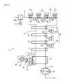
- the hydrogen production plant 1 shown is a device for producing hydrogen at cryogenic temperature, in particular liquefied hydrogen.
- This installation 1 comprises an electrolyser 2, preferably of the “PEM” type (proton exchange membrane) operating at high pressure, that is to say producing hydrogen and oxygen gas at pressures between 15 and 150 bar, for example equal to 30 bar.
- PEM proto exchange membrane
- Electrolyzer 2 has an oxygen outlet and a hydrogen outlet.
- the assembly comprising the expansion turbine 13 and the compressor 12 coupled to the same rotating shaft 14 is preferably a passive mechanical system, that is to say that it does not include any drive motor of the rotating shaft 14 other than the oxygen flow.
- the expansion turbine 13 is mechanically braked by the compressor 12 coupled to the same shaft 14.
- this is not limiting, it could thus be envisaged to provide a system with a motor whose shaft is coupled to the turbine(s) and compressor(s) (to improve the efficiency of the installation if appropriate).
- This transfer of work achieves a “turbo boosting” which therefore consists of integrating one or more cryogenic expansion turbines 13 for which the working fluid is the oxygen previously produced by the electrolyser 2.
- the braking system of these turbines is one or more compressors 12 coupled to the same shaft 14. This makes it possible to inject the expansion work of this gas flow as a booster for the upstream flow at ambient temperature.
- the oxygen circuit 190 comprises as many compressors 12 arranged in series upstream as expansion turbines 13 arranged in series downstream, the compressors and turbines 13 are coupled in pairs on respective rotating shafts 14.
- the first turbine (upstream) is coupled with the first compressor (upstream), the second turbine with the second compressor, etc.
- an oxygen cooling system 21 is provided at the outlet of at least some of the compressors 12.
- a cooler cooling exchanger in exchange with a fluid such as air or water
- a fluid such as air or water
- the set of heat exchanger(s) 4, 5, 6, 7, 8 thus preferably comprises several heat exchangers arranged in series and in heat exchange with the hydrogen circuit 3 to be cooled between the upstream and downstream ends of the hydrogen circuit 3 to be cooled.
- This pre-cooling of the hydrogen can be completed downstream of the circuit 3 by a second cooling device 10 in heat exchange with the hydrogen circuit 3 to be cooled.
- the first aforementioned cooling device 9 expanded oxygen
- the second cooling device 10 can be placed in heat exchange with a second group of heat exchangers 8 downstream (symbolized here by a single heat exchanger but several heat exchangers in series and/or in parallel can be envisaged).
- the hydrogen circuit 3 preferably comprises several hydrogen compressors 19 arranged in series upstream of the hydrogen flow expansion system 18.
- the hydrogen flow expansion system preferably comprises as many expansion turbines 18 arranged in series, each of the compressors 19 being coupled to a rotating shaft 20 on which at least one turbine 18 is also coupled.
- the compressors 19 and turbines are associated in pairs on respective distinct rotating shafts 20 (for example first upstream compressor 19 coupled with the first upstream turbine 20 etc.).
- expansion stages 18 make it possible to enhance the pressure of the hydrogen flow (with or without intermediate cooling). This makes it possible to replace or supplement the pre-cooling described above.
- this method of expansion and valorization of the pressure of the hydrogen flow is not limited to this example.
- the expansion of hydrogen from ambient temperature to a determined pre-cooling temperature could be carried out in several radial expansion stages or in a single expansion stage, for example via a volumetric expander, in particular to reduce costs.
- the compressors 19 of the hydrogen flow are located upstream of the first group of pre-cooling exchangers 4, 5, 6, 7 (for example at ambient temperature) and the turbines in the pre-cooling part (heat exchange at the outlet of the turbines 18 with these pre-cooling heat exchangers 4, 5, 6, 7).
- the method of realization of the [ Fig. 3 ] is distinguished from that of the [ Fig. 2 ] essentially in that the compressors 19 of the hydrogen flow are located downstream of the first group of pre-cooling exchangers 4, 5, 6 and upstream of the second group of cooling exchangers 8 (in the part of the circuit 3 where the hydrogen is already pre-cooled). That is to say that the compression of the hydrogen flow is carried out after pre-cooling and before final cooling. This makes it possible to obtain a higher compression ratio on a very light H2 molecule (molar mass -2 g/mol).
- the expansion turbines 18 are intercalated in the cooling part (heat exchange at the outlet of the turbines 18 with these heat exchangers 8 of the second group).
- the method of realization of the [ Fig. 4 ] is distinguished from that of the [ Fig. 3 ] essentially in that the compressors 19 of the hydrogen flow are located upstream of the first group of pre-cooling exchangers. That is to say that the compression of the hydrogen flow is carried out before pre-cooling (at ambient temperature for example) while the expansion is carried out in the cold part of cooling (after pre-cooling).
- the second refrigeration device 10 may comprise one or more turbines 16 in series and/or in parallel.
- the flows upstream and downstream of the compressor(s) 15 may exchange heat in counter-current in the same heat exchanger 150.
- the flow(s) at the outlet of the turbine(s) may optionally exchange in the heat exchanger(s) 8 of the second group (dotted line representation).
- the turbines are preferably of the radial and centripetal technology type. This allows for the sharing of expansion technologies across the entire liquefaction installation.
- the compressors are preferably of the centrifugal type.
- the oxygen circuit 190 produces liquefied oxygen downstream which is recovered.
- all or part of the oxygen flow can pass through heat exchangers separate from the exchangers 4, 5, 6, 7, 8 in exchange with the hydrogen flow.
Landscapes
- Engineering & Computer Science (AREA)
- Physics & Mathematics (AREA)
- Mechanical Engineering (AREA)
- Thermal Sciences (AREA)
- General Engineering & Computer Science (AREA)
- Chemical & Material Sciences (AREA)
- Health & Medical Sciences (AREA)
- Emergency Medicine (AREA)
- Inorganic Chemistry (AREA)
- Chemical Kinetics & Catalysis (AREA)
- Electrochemistry (AREA)
- Materials Engineering (AREA)
- Metallurgy (AREA)
- Organic Chemistry (AREA)
- Separation By Low-Temperature Treatments (AREA)
- Electrolytic Production Of Non-Metals, Compounds, Apparatuses Therefor (AREA)
Claims (19)
- Anlage zur Herstellung von Wasserstoff bei Kryogen-Temperatur, insbesondere von Flüssigwasserstoff, umfassend einen Elektrolyseur (2), der mit einem Sauerstoffauslass und einem Wasserstoffauslass ausgestattet ist, einen Kreislauf (3) von zu kühlendem Wasserstoff, umfassend ein stromaufwärts gelegenes Ende, das mit dem Wasserstoffauslass verbunden ist, und ein stromabwärts gelegenes Ende, das dazu bestimmt ist, mit einem Element (23) zum Auffangen des gekühlten und/oder verflüssigten Wasserstoffs verbunden zu werden, wobei die Anlage (1) eine Wärmetauschereinheit bzw. Einheit von Wärmetauschern (4, 5, 6, 7, 8) umfasst, die mit dem Kreislauf von zu kühlendem Wasserstoff (3) im Wärmeaustausch steht, wobei die Anlage (1) mindestens eine Kühlvorrichtung (9, 10) umfasst, die mit mindestens einem Teil der Wärmetauschereinheit bzw. Einheit von Wärmetauschern (4, 5, 6, 7, 8) im Wärmeaustausch steht, wobei die Anlage (1) einen Sauerstoffkreislauf (190) umfasst, umfassend ein stromaufwärts gelegenes Ende, das mit dem Sauerstoffauslass verbunden ist, und ein stromabwärts gelegenes Ende (11), wobei der Sauerstoffkreislauf (190) ein System (13) zum Entspannen des Sauerstoffstroms und mindestens einen Wärmeaustausch zwischen dem entspannten Sauerstoffstrom und dem Kreislauf von zu kühlendem Wasserstoff (3) umfasst, wobei der Sauerstoffkreislauf (190) mindestens einen Sauerstoffkompressor (12) umfasst, der stromaufwärts des Sauerstoffstromentspannungssystems (13) angeordnet ist, wobei das Sauerstoffstromentspannungssystem (13) eine Entspannungsturbine (13) umfasst, dadurch gekennzeichnet, dass die Entspannungsturbine (13) und der Kompressor (12) mit einer gleichen rotierenden Welle (14) gekoppelt sind, um Entspannungsarbeit des Sauerstoffstroms unter Druck in den Kompressor (12) zum Komprimieren des Sauerstoffstroms stromaufwärts der Turbine (13) zu übertragen.
- Anlage nach Anspruch 1, dadurch gekennzeichnet, dass die Einheit, die die Entspannungsturbine (13) und den Kompressor (12) umfasst, die mit einer gleichen rotierenden Welle (14) gekoppelt sind, ein passives mechanisches System ist, d. h. dass sie keinen anderen Motor zum Antrieb der rotierenden Welle (14) als den Sauerstoffstrom umfasst, oder dass die Einheit, die die Entspannungsturbine (13) und den Kompressor (12) umfasst, die mit einer gleichen rotierenden Welle (14) gekoppelt sind, ein aktives mechanisches System ist, d. h. einen Motor zum Antrieb der rotierenden Welle (14) aufweist.
- Anlage nach Anspruch 1 oder 2, dadurch gekennzeichnet, dass der Sauerstoffkreislauf (190) mehrere in Reihe und/oder parallel stromaufwärts des Sauerstoffstromentspannungssystems (13) angeordnete Sauerstoffkompressoren (12) umfasst, wobei das Sauerstoffstromentspannungssystem eine Mehrzahl an Entspannungsturbinen (13) umfasst, und dadurch, dass jeder der Kompressoren (12) mit einer rotierenden Welle (14) gekoppelt ist, an die auch mindestens eine Turbine (13) gekoppelt ist.
- Anlage nach einem der Ansprüche 1 bis 3, dadurch gekennzeichnet, dass der Sauerstoffkreislauf (190) mehrere in Reihe stromaufwärts des Sauerstoffstromentspannungssystems (13) angeordnete Kompressoren (12) umfasst, wobei das Sauerstoffstromentspannungssystem (13) eine Mehrzahl an Entspannungsturbinen (13) umfasst, und dadurch, dass die Kompressoren und Turbinen (13) jeweils paarweise an rotierende Wellen (14) gekoppelt sind.
- Anlage nach einem der Ansprüche 3 und 4, dadurch gekennzeichnet, dass die Turbinen (14) in Reihe im Sauerstoffkreislauf (190) angeordnet sind, wobei der Sauerstoffkreislauf (190) jeweils getrennte Wärmeaustauschabschnitte zwischen der Wärmetauschereinheit bzw. der Einheit von Wärmetauschern (4, 5, 6, 7, 8) und dem Sauerstoffstrom am Auslass jeder Turbine (13) umfasst, wobei die Anlage gegebenenfalls ein System (21) zur Kühlung des Sauerstoffs am Auslass zumindest eines Teils der Kompressoren (12) umfasst.
- Anlage nach einem der Ansprüche 1 bis 5, dadurch gekennzeichnet, dass die Wärmetauschereinheit bzw. die Einheit von Wärmetauschern (4, 5, 6, 7, 8) mehrere Wärmetauscher umfasst, die in Reihe und im Wärmeaustausch mit dem Kreislauf von zu kühlendem Wasserstoff (3) zwischen dem stromaufwärts und dem stromabwärts gelegenen Ende des Kreislauf von zu kühlendem Wasserstoff (3) angeordnet sind.
- Anlage nach Anspruch 6, dadurch gekennzeichnet, dass sie eine erste Kühlvorrichtung (9) und eine zweite Kühlvorrichtung (10) aufweist, die im Wärmeaustausch mit dem Kreislauf von zu kühlendem Wasserstoff (3) stehen, wobei die erste Kühlvorrichtung (9) im Wärmeaustausch mit einer ersten Wärmetauschergruppe bzw. Gruppe von Wärmetauschern (4, 5, 6, 7) der Wärmetauschereinheit bzw. der Einheit von Wärmetauschern (4, 5, 6, 7, 8) steht, wobei die zweite Kühlvorrichtung (10) im Wärmeaustausch mit einer zweiten Gruppe von Wärmetauschern (8) steht, wobei die erste Wärmetauschergruppe bzw. Gruppe von Wärmetauschern (4, 5, 6, 7) sich stromaufwärts der zweiten Gruppe von Wärmetauschern (8) im Kreislauf von zu kühlendem Wasserstoff (3) befindet, und dadurch, dass die erste Kühlvorrichtung (9) den Wärmeaustausch zwischen dem entspannten Sauerstoffstrom und dem Kreislauf von zu kühlendem Wasserstoff (3) umfasst, so dass eine Vorkühlung des Wasserstoffkreislaufs (3) vor der zusätzlichen Kühlung, die durch die zweite Kühlvorrichtung (10) erfolgt, sichergestellt wird.
- Anlage nach Anspruch 7, dadurch gekennzeichnet, dass die zweite Kühlvorrichtung (10) ein Kühlgerät mit einem Kühlkreislauf eines Kreislaufgases umfasst, wobei das Kühlgerät der zweiten Kühlvorrichtung (10), in Reihe in einem Kreislauf angeordnet, Folgendes umfasst: einen Mechanismus zur Kompression des zweiten Kreislaufgases (15), ein Element (24) zum Kühlen des zweiten Kreislaufgases, einen Mechanismus (16) zum Entspannen des zweiten Kreislaufgases und ein Element (8) zum Erhitzen des entspannten zweiten Kreislaufgases.
- Anlage nach Anspruch 7 oder 8, dadurch gekennzeichnet, dass sie eine dritte Kühlvorrichtung (17) umfasst, die im Wärmeaustausch mit mindestens einem Teil der ersten Wärmetauschergruppe bzw. Gruppe von Wärmetauschern (4, 5, 6, 7) steht.
- Anlage nach einem der Ansprüche 1 bis 9, dadurch gekennzeichnet, dass der Kreislauf von zu kühlendem Wasserstoff (3) ein System (18) zum Entspannen des Wasserstoffstroms umfasst, wobei der Kreislauf von zu kühlendem Wasserstoff (3) mindestens einen Wasserstoffkompressor (19) stromaufwärts des Wasserstoffstromentspannungssystems (18) umfasst, wobei das Wasserstoffstromentspannungssystem (18) eine Entspannungsturbine (18) umfasst, und dadurch, dass die Entspannungsturbine (18) und der Kompressor (19) mit einer gleichen rotierenden Welle (20) gekoppelt sind, um Entspannungsarbeit des Wasserstoffstroms unter Druck in den Kompressor (19) zum Komprimieren des Wasserstoffstroms stromaufwärts der Turbine (18) zu übertragen.
- Anlage nach Anspruch 10, dadurch gekennzeichnet, dass die mit einer gleichen rotierenden Welle (20) gekoppelte Einheit von Entspannungsturbine (18) und Kompressor (19) ein passives mechanisches System ist, d. h. dass sie keinen anderen Motor zum Antrieb der rotierenden Welle (20) als den Wasserstoffstrom umfasst.
- Anlage nach Anspruch 10 oder 11, dadurch gekennzeichnet, dass der Wasserstoffkreislauf (3) mehrere Wasserstoffkompressoren (19) umfasst, die in Reihe und/oder parallel stromaufwärts des Wasserstoffstromentspannungssystems (18) angeordnet sind, wobei das Wasserstoffstromentspannungssystem eine Mehrzahl von in Reihe und/oder parallel angeordneten Entspannungsturbinen (18) umfasst, und dadurch, dass jeder der Kompressoren (19) mit einer rotierenden Welle (20) gekoppelt ist, mit der auch mindestens eine Turbine (18) gekoppelt ist.
- Anlage nach Anspruch 11 oder 12, dadurch gekennzeichnet, dass der Kreislauf von zu kühlendem Wasserstoff (3) mehrere in Reihe stromaufwärts des Wasserstoffstromentspannungssystems (18) angeordnete Kompressoren (19) umfasst, wobei das Wasserstoffstromentspannungssystem eine Mehrzahl an in Reihe angeordneten Entspannungsturbinen (18) umfasst, und dadurch, dass die Kompressoren und Turbinen (18) paarweise mit entsprechenden rotierenden Wellen (20) gekoppelt sind.
- Anlage nach Anspruch 11 oder 12, dadurch gekennzeichnet, dass die Turbinen (18) in Reihe in dem Kreislauf von zu kühlendem Wasserstoff (3) angeordnet sind, wobei der Kreislauf von zu kühlendem Wasserstoff (3) jeweils getrennte Wärmeaustauschabschnitte zwischen der Wärmetauschereinheit bzw. der Einheit von Wärmetauschern (4, 5, 6, 7, 8) und dem Wasserstoffstrom am Auslass jeder Turbine (18) aufweist.
- Anlage nach einem der Ansprüche 7 bis 8 in Kombination mit einem der Ansprüche 9 bis 13, dadurch gekennzeichnet, dass sich das Wasserstoffstromentspannungssystem (18) an einem Teil des Kreislaufs von zu kühlendem Wasserstoff (3) befindet, der im Wärmeaustausch mit der ersten Wärmetauschergruppe bzw. Gruppe von Wärmetauschern (4, 5, 6, 7) steht.
- Anlage nach einem der Ansprüche 7 bis 8 in Kombination mit einem der Ansprüche 9 bis 13, dadurch gekennzeichnet, dass sich das Wasserstoffstromentspannungssystem (18) an einem Teil des Kreislaufs von zu kühlendem Wasserstoff (3) befindet, der im Wärmeaustausch mit der zweiten Wärmetauschergruppe bzw. Gruppe von Wärmetauschern (8) steht.
- Anlage nach einem der Ansprüche 12 bis 16, dadurch gekennzeichnet, dass sie ein Wasserstoffskühlsystem (22) am Auslass wenigstens eines Teils der Kompressoren (19) umfasst.
- Verfahren zur Herstellung von Wasserstoff bei Kryogen-Temperatur, insbesondere von Flüssigwasserstoff, unter Verwendung einer Anlage (1) nach einem der vorhergehenden Ansprüche, wobei das Verfahren einen Schritt der Bereitstellung, durch den Elektrolyseur (2), eines Wasserstoffstroms am stromaufwärts gelegenen Ende des Wasserstoffkreislaufs (3), zum Beispiel bei einem Druck zwischen 15 und 150 bar, einen Schritt der Bereitstellung, durch den Elektrolyseur (2), eines Sauerstoffstroms am stromaufwärts gelegenen Ende des Sauerstoffkreislaufs (190), zum Beispiel bei einem Druck zwischen 15 und 150 bar, umfasst, wobei das Verfahren einen Schritt der Kompression und der anschließenden Entspannung des Sauerstoffstroms umfasst, wobei die Entspannung durch die mindestens eine Turbine (13) erfolgt, die mit der Welle (14) gekoppelt ist, wobei die Welle (14) außerdem mit mindestens einem Kompressor (12) gekoppelt ist, so dass die Kompression des Sauerstoffstroms vor seiner Entspannung sichergestellt wird, wobei das Verfahren einen Wärmeaustausch zwischen dem entspannten Sauerstoffstrom mit dem Wasserstoffstrom zu dessen Kühlung umfasst.
- Verfahren nach Anspruch 18, dadurch gekennzeichnet, dass das Verfahren einen Schritt der Kompression und der anschließenden Entspannung des Wasserstoffstroms zu dessen Kühlung umfasst, wobei die Entspannung durch mindestens eine Turbine (18) erfolgt, die mit einer Welle (20) gekoppelt ist, wobei die Welle (20) außerdem mit mindestens einem Kompressor (19) gekoppelt ist, so dass die Kompression des Wasserstoffstroms vor dessen Entspannung sichergestellt wird.
Applications Claiming Priority (2)
| Application Number | Priority Date | Filing Date | Title |
|---|---|---|---|
| FR2011490A FR3116106B1 (fr) | 2020-11-09 | 2020-11-09 | Installation et procédé de production d’hydrogène à température cryogénique |
| PCT/EP2021/077673 WO2022096217A1 (fr) | 2020-11-09 | 2021-10-07 | Installation et procédé de production d'hydrogène a temperature cryogenique |
Publications (2)
| Publication Number | Publication Date |
|---|---|
| EP4241027A1 EP4241027A1 (de) | 2023-09-13 |
| EP4241027B1 true EP4241027B1 (de) | 2024-12-04 |
Family
ID=74758919
Family Applications (1)
| Application Number | Title | Priority Date | Filing Date |
|---|---|---|---|
| EP21787459.3A Active EP4241027B1 (de) | 2020-11-09 | 2021-10-07 | Anlage und verfahren zur herstellung von wasserstoff bei kryogener temperatur |
Country Status (6)
| Country | Link |
|---|---|
| US (1) | US20240019203A1 (de) |
| EP (1) | EP4241027B1 (de) |
| JP (1) | JP2023548010A (de) |
| KR (1) | KR20230104881A (de) |
| FR (1) | FR3116106B1 (de) |
| WO (1) | WO2022096217A1 (de) |
Families Citing this family (3)
| Publication number | Priority date | Publication date | Assignee | Title |
|---|---|---|---|---|
| CN115451655B (zh) * | 2022-09-29 | 2023-04-28 | 北京飞燕石化环保科技发展有限公司 | 一种空分装置 |
| DE102023201841A1 (de) * | 2023-03-01 | 2024-09-05 | Siemens Energy Global GmbH & Co. KG | Elektrolyseanlage mit einem Druckelektrolyseur und Verfahren zum Betrieb einer Elektrolyseanlage |
| WO2024223491A1 (en) * | 2023-04-24 | 2024-10-31 | L'air Liquide, Societe Anonyme Pour L'etude Et L'exploitation Des Procedes Georges Claude | Process and apparatus for air separation by cryogenic distillation |
Citations (1)
| Publication number | Priority date | Publication date | Assignee | Title |
|---|---|---|---|---|
| US10351962B2 (en) * | 2014-07-01 | 2019-07-16 | Siemens Aktiengesellschaft | Method for operating an electrolytic system and electrolytic system |
Family Cites Families (8)
| Publication number | Priority date | Publication date | Assignee | Title |
|---|---|---|---|---|
| GB2142423B (en) | 1983-03-10 | 1986-08-06 | Smith Dr Eric Murray | Production of liquid hydrogen |
| JP2004210597A (ja) * | 2003-01-06 | 2004-07-29 | Toshiba Corp | 排熱利用水素・酸素システムおよび液体水素の製造方法 |
| JP2007205667A (ja) * | 2006-02-03 | 2007-08-16 | Mitsubishi Heavy Ind Ltd | 液化水素製造装置 |
| WO2008115933A1 (en) * | 2007-03-19 | 2008-09-25 | Doty Scientific, Inc. | Hydrocarbon and alcohol fuels from variable, renewable energy at very high efficiency |
| EP3162871A1 (de) * | 2015-10-27 | 2017-05-03 | Linde Aktiengesellschaft | Kältekreislauf mit wasserstoff-neon-mischung zur wasserstoffmassekühlung oder -verflüssigung |
| FR3053771B1 (fr) * | 2016-07-06 | 2019-07-19 | Saipem S.P.A. | Procede de liquefaction de gaz naturel et de recuperation d'eventuels liquides du gaz naturel comprenant deux cycles refrigerant semi-ouverts au gaz naturel et un cycle refrigerant ferme au gaz refrigerant |
| US10634425B2 (en) * | 2016-08-05 | 2020-04-28 | L'air Liquide, Societe Anonyme Pour L'etude Et L'exploitation Des Procedes Georges Claude | Integration of industrial gas site with liquid hydrogen production |
| WO2022093762A1 (en) * | 2020-10-26 | 2022-05-05 | JTurbo Engineering & Technology, LLC | Methods and configurations for lng liquefaction |
-
2020
- 2020-11-09 FR FR2011490A patent/FR3116106B1/fr active Active
-
2021
- 2021-10-07 WO PCT/EP2021/077673 patent/WO2022096217A1/fr not_active Ceased
- 2021-10-07 JP JP2023521460A patent/JP2023548010A/ja active Pending
- 2021-10-07 KR KR1020237014936A patent/KR20230104881A/ko active Pending
- 2021-10-07 US US18/036,125 patent/US20240019203A1/en active Pending
- 2021-10-07 EP EP21787459.3A patent/EP4241027B1/de active Active
Patent Citations (1)
| Publication number | Priority date | Publication date | Assignee | Title |
|---|---|---|---|---|
| US10351962B2 (en) * | 2014-07-01 | 2019-07-16 | Siemens Aktiengesellschaft | Method for operating an electrolytic system and electrolytic system |
Also Published As
| Publication number | Publication date |
|---|---|
| EP4241027A1 (de) | 2023-09-13 |
| FR3116106B1 (fr) | 2022-10-07 |
| FR3116106A1 (fr) | 2022-05-13 |
| JP2023548010A (ja) | 2023-11-15 |
| US20240019203A1 (en) | 2024-01-18 |
| WO2022096217A1 (fr) | 2022-05-12 |
| KR20230104881A (ko) | 2023-07-11 |
Similar Documents
| Publication | Publication Date | Title |
|---|---|---|
| EP4241027B1 (de) | Anlage und verfahren zur herstellung von wasserstoff bei kryogener temperatur | |
| EP3732743B1 (de) | Energieerzeugungsanlage mit kopplung einer brennstoffzelle und eines reversiblen thermodynamischen systems | |
| US20120255312A1 (en) | Method and System to Produce Electric Power | |
| EP4241028A1 (de) | Anlage und verfahren zur herstellung von wasserstoff bei kryogener temperatur | |
| EP4291838B1 (de) | Vorrichtung und verfahren zur verflüssigung eines fluids wie wasserstoff und/oder helium | |
| EP4291843B1 (de) | Vorrichtung und verfahren zur verflüssigung eines fluids wie wasserstoff und/oder helium | |
| FR3149079A1 (fr) | Installation et procédé de liquéfaction d’hydrogène | |
| EP4551876A1 (de) | Verfahren und vorrichtung zur verflüssigung von flüssigkeiten | |
| EP4348138A1 (de) | Verfahren und anlage zur wasserstoffverflüssigung | |
| FR3134619A3 (fr) | Installation et procédé de production d’oxygène à température cryogénique | |
| EP3990846A1 (de) | Anlage und verfahren zur verflüssigung von gas | |
| JP2004150685A (ja) | 窒素製造設備及びタービン発電設備 | |
| EP4226107A1 (de) | Anlage und verfahren zur kühlung und/oder verflüssigung eines fluids | |
| FR3035195B1 (fr) | Installation et procede de production d'helium liquide | |
| WO2025002660A1 (fr) | Installation et procédé de liquéfaction d'un fluide | |
| EP4567358A1 (de) | Anlage und verfahren zur herstellung von verflüssigtem wasserstoff | |
| FR3150850A1 (fr) | Réfrigérateur à cycle de réfrigération et dispositif et procédé de liquéfaction | |
| WO2022263754A1 (fr) | Systeme de recuperation d'energie de compression d'un gaz, liquefacteur comprenant un tel systeme et procede de recuperation d'energie de compression d'un gaz | |
| CN119712500A (zh) | 液态空气储能发电系统及方法 | |
| WO2024153378A1 (fr) | Installation et procédé de liquéfaction d'un flux de fluide |
Legal Events
| Date | Code | Title | Description |
|---|---|---|---|
| STAA | Information on the status of an ep patent application or granted ep patent |
Free format text: STATUS: UNKNOWN |
|
| STAA | Information on the status of an ep patent application or granted ep patent |
Free format text: STATUS: THE INTERNATIONAL PUBLICATION HAS BEEN MADE |
|
| PUAI | Public reference made under article 153(3) epc to a published international application that has entered the european phase |
Free format text: ORIGINAL CODE: 0009012 |
|
| STAA | Information on the status of an ep patent application or granted ep patent |
Free format text: STATUS: REQUEST FOR EXAMINATION WAS MADE |
|
| 17P | Request for examination filed |
Effective date: 20230609 |
|
| AK | Designated contracting states |
Kind code of ref document: A1 Designated state(s): AL AT BE BG CH CY CZ DE DK EE ES FI FR GB GR HR HU IE IS IT LI LT LU LV MC MK MT NL NO PL PT RO RS SE SI SK SM TR |
|
| DAV | Request for validation of the european patent (deleted) | ||
| DAX | Request for extension of the european patent (deleted) | ||
| GRAP | Despatch of communication of intention to grant a patent |
Free format text: ORIGINAL CODE: EPIDOSNIGR1 |
|
| STAA | Information on the status of an ep patent application or granted ep patent |
Free format text: STATUS: GRANT OF PATENT IS INTENDED |
|
| RIC1 | Information provided on ipc code assigned before grant |
Ipc: C25B 1/04 20210101ALI20240610BHEP Ipc: F25J 1/02 20060101ALI20240610BHEP Ipc: F25J 1/00 20060101AFI20240610BHEP |
|
| GRAJ | Information related to disapproval of communication of intention to grant by the applicant or resumption of examination proceedings by the epo deleted |
Free format text: ORIGINAL CODE: EPIDOSDIGR1 |
|
| STAA | Information on the status of an ep patent application or granted ep patent |
Free format text: STATUS: REQUEST FOR EXAMINATION WAS MADE |
|
| GRAP | Despatch of communication of intention to grant a patent |
Free format text: ORIGINAL CODE: EPIDOSNIGR1 |
|
| STAA | Information on the status of an ep patent application or granted ep patent |
Free format text: STATUS: GRANT OF PATENT IS INTENDED |
|
| INTG | Intention to grant announced |
Effective date: 20240710 |
|
| INTG | Intention to grant announced |
Effective date: 20240729 |
|
| GRAS | Grant fee paid |
Free format text: ORIGINAL CODE: EPIDOSNIGR3 |
|
| GRAA | (expected) grant |
Free format text: ORIGINAL CODE: 0009210 |
|
| STAA | Information on the status of an ep patent application or granted ep patent |
Free format text: STATUS: THE PATENT HAS BEEN GRANTED |
|
| AK | Designated contracting states |
Kind code of ref document: B1 Designated state(s): AL AT BE BG CH CY CZ DE DK EE ES FI FR GB GR HR HU IE IS IT LI LT LU LV MC MK MT NL NO PL PT RO RS SE SI SK SM TR |
|
| REG | Reference to a national code |
Ref country code: CH Ref legal event code: EP |
|
| REG | Reference to a national code |
Ref country code: DE Ref legal event code: R096 Ref document number: 602021022948 Country of ref document: DE |
|
| REG | Reference to a national code |
Ref country code: IE Ref legal event code: FG4D Free format text: LANGUAGE OF EP DOCUMENT: FRENCH |
|
| REG | Reference to a national code |
Ref country code: NL Ref legal event code: FP |
|
| REG | Reference to a national code |
Ref country code: LT Ref legal event code: MG9D |
|
| PG25 | Lapsed in a contracting state [announced via postgrant information from national office to epo] |
Ref country code: HR Free format text: LAPSE BECAUSE OF FAILURE TO SUBMIT A TRANSLATION OF THE DESCRIPTION OR TO PAY THE FEE WITHIN THE PRESCRIBED TIME-LIMIT Effective date: 20241204 |
|
| PG25 | Lapsed in a contracting state [announced via postgrant information from national office to epo] |
Ref country code: FI Free format text: LAPSE BECAUSE OF FAILURE TO SUBMIT A TRANSLATION OF THE DESCRIPTION OR TO PAY THE FEE WITHIN THE PRESCRIBED TIME-LIMIT Effective date: 20241204 |
|
| PG25 | Lapsed in a contracting state [announced via postgrant information from national office to epo] |
Ref country code: BG Free format text: LAPSE BECAUSE OF FAILURE TO SUBMIT A TRANSLATION OF THE DESCRIPTION OR TO PAY THE FEE WITHIN THE PRESCRIBED TIME-LIMIT Effective date: 20241204 |
|
| PG25 | Lapsed in a contracting state [announced via postgrant information from national office to epo] |
Ref country code: ES Free format text: LAPSE BECAUSE OF FAILURE TO SUBMIT A TRANSLATION OF THE DESCRIPTION OR TO PAY THE FEE WITHIN THE PRESCRIBED TIME-LIMIT Effective date: 20241204 |
|
| PG25 | Lapsed in a contracting state [announced via postgrant information from national office to epo] |
Ref country code: LV Free format text: LAPSE BECAUSE OF FAILURE TO SUBMIT A TRANSLATION OF THE DESCRIPTION OR TO PAY THE FEE WITHIN THE PRESCRIBED TIME-LIMIT Effective date: 20241204 Ref country code: GR Free format text: LAPSE BECAUSE OF FAILURE TO SUBMIT A TRANSLATION OF THE DESCRIPTION OR TO PAY THE FEE WITHIN THE PRESCRIBED TIME-LIMIT Effective date: 20250305 |
|
| PG25 | Lapsed in a contracting state [announced via postgrant information from national office to epo] |
Ref country code: RS Free format text: LAPSE BECAUSE OF FAILURE TO SUBMIT A TRANSLATION OF THE DESCRIPTION OR TO PAY THE FEE WITHIN THE PRESCRIBED TIME-LIMIT Effective date: 20250304 |
|
| REG | Reference to a national code |
Ref country code: AT Ref legal event code: MK05 Ref document number: 1748581 Country of ref document: AT Kind code of ref document: T Effective date: 20241204 |
|
| PG25 | Lapsed in a contracting state [announced via postgrant information from national office to epo] |
Ref country code: SM Free format text: LAPSE BECAUSE OF FAILURE TO SUBMIT A TRANSLATION OF THE DESCRIPTION OR TO PAY THE FEE WITHIN THE PRESCRIBED TIME-LIMIT Effective date: 20241204 |
|
| PG25 | Lapsed in a contracting state [announced via postgrant information from national office to epo] |
Ref country code: PL Free format text: LAPSE BECAUSE OF FAILURE TO SUBMIT A TRANSLATION OF THE DESCRIPTION OR TO PAY THE FEE WITHIN THE PRESCRIBED TIME-LIMIT Effective date: 20241204 |
|
| PG25 | Lapsed in a contracting state [announced via postgrant information from national office to epo] |
Ref country code: IS Free format text: LAPSE BECAUSE OF FAILURE TO SUBMIT A TRANSLATION OF THE DESCRIPTION OR TO PAY THE FEE WITHIN THE PRESCRIBED TIME-LIMIT Effective date: 20250404 |
|
| PG25 | Lapsed in a contracting state [announced via postgrant information from national office to epo] |
Ref country code: PT Free format text: LAPSE BECAUSE OF FAILURE TO SUBMIT A TRANSLATION OF THE DESCRIPTION OR TO PAY THE FEE WITHIN THE PRESCRIBED TIME-LIMIT Effective date: 20250404 |
|
| PG25 | Lapsed in a contracting state [announced via postgrant information from national office to epo] |
Ref country code: EE Free format text: LAPSE BECAUSE OF FAILURE TO SUBMIT A TRANSLATION OF THE DESCRIPTION OR TO PAY THE FEE WITHIN THE PRESCRIBED TIME-LIMIT Effective date: 20241204 |
|
| PG25 | Lapsed in a contracting state [announced via postgrant information from national office to epo] |
Ref country code: RO Free format text: LAPSE BECAUSE OF FAILURE TO SUBMIT A TRANSLATION OF THE DESCRIPTION OR TO PAY THE FEE WITHIN THE PRESCRIBED TIME-LIMIT Effective date: 20241204 Ref country code: AT Free format text: LAPSE BECAUSE OF FAILURE TO SUBMIT A TRANSLATION OF THE DESCRIPTION OR TO PAY THE FEE WITHIN THE PRESCRIBED TIME-LIMIT Effective date: 20241204 |
|
| PG25 | Lapsed in a contracting state [announced via postgrant information from national office to epo] |
Ref country code: SK Free format text: LAPSE BECAUSE OF FAILURE TO SUBMIT A TRANSLATION OF THE DESCRIPTION OR TO PAY THE FEE WITHIN THE PRESCRIBED TIME-LIMIT Effective date: 20241204 |
|
| PG25 | Lapsed in a contracting state [announced via postgrant information from national office to epo] |
Ref country code: CZ Free format text: LAPSE BECAUSE OF FAILURE TO SUBMIT A TRANSLATION OF THE DESCRIPTION OR TO PAY THE FEE WITHIN THE PRESCRIBED TIME-LIMIT Effective date: 20241204 |
|
| PG25 | Lapsed in a contracting state [announced via postgrant information from national office to epo] |
Ref country code: IT Free format text: LAPSE BECAUSE OF FAILURE TO SUBMIT A TRANSLATION OF THE DESCRIPTION OR TO PAY THE FEE WITHIN THE PRESCRIBED TIME-LIMIT Effective date: 20241204 |
|
| REG | Reference to a national code |
Ref country code: DE Ref legal event code: R097 Ref document number: 602021022948 Country of ref document: DE |
|
| PG25 | Lapsed in a contracting state [announced via postgrant information from national office to epo] |
Ref country code: SE Free format text: LAPSE BECAUSE OF FAILURE TO SUBMIT A TRANSLATION OF THE DESCRIPTION OR TO PAY THE FEE WITHIN THE PRESCRIBED TIME-LIMIT Effective date: 20241204 |
|
| PG25 | Lapsed in a contracting state [announced via postgrant information from national office to epo] |
Ref country code: DK Free format text: LAPSE BECAUSE OF FAILURE TO SUBMIT A TRANSLATION OF THE DESCRIPTION OR TO PAY THE FEE WITHIN THE PRESCRIBED TIME-LIMIT Effective date: 20241204 |
|
| PLBE | No opposition filed within time limit |
Free format text: ORIGINAL CODE: 0009261 |
|
| STAA | Information on the status of an ep patent application or granted ep patent |
Free format text: STATUS: NO OPPOSITION FILED WITHIN TIME LIMIT |
|
| 26N | No opposition filed |
Effective date: 20250905 |
|
| PGFP | Annual fee paid to national office [announced via postgrant information from national office to epo] |
Ref country code: NL Payment date: 20251021 Year of fee payment: 5 |
|
| PGFP | Annual fee paid to national office [announced via postgrant information from national office to epo] |
Ref country code: DE Payment date: 20251021 Year of fee payment: 5 |
|
| PGFP | Annual fee paid to national office [announced via postgrant information from national office to epo] |
Ref country code: NO Payment date: 20251024 Year of fee payment: 5 |
|
| PGFP | Annual fee paid to national office [announced via postgrant information from national office to epo] |
Ref country code: FR Payment date: 20251030 Year of fee payment: 5 |
|
| PGFP | Annual fee paid to national office [announced via postgrant information from national office to epo] |
Ref country code: BE Payment date: 20251021 Year of fee payment: 5 |