EP4240897B1 - Zweischichtiges mehrlitziges kabel mit einer internen beschichtung mit verbesserter durchlässigkeit - Google Patents
Zweischichtiges mehrlitziges kabel mit einer internen beschichtung mit verbesserter durchlässigkeit Download PDFInfo
- Publication number
- EP4240897B1 EP4240897B1 EP21810406.5A EP21810406A EP4240897B1 EP 4240897 B1 EP4240897 B1 EP 4240897B1 EP 21810406 A EP21810406 A EP 21810406A EP 4240897 B1 EP4240897 B1 EP 4240897B1
- Authority
- EP
- European Patent Office
- Prior art keywords
- layer
- external
- strand
- internal
- cord
- Prior art date
- Legal status (The legal status is an assumption and is not a legal conclusion. Google has not performed a legal analysis and makes no representation as to the accuracy of the status listed.)
- Active
Links
Images


Classifications
-
- D—TEXTILES; PAPER
- D07—ROPES; CABLES OTHER THAN ELECTRIC
- D07B—ROPES OR CABLES IN GENERAL
- D07B1/00—Constructional features of ropes or cables
- D07B1/06—Ropes or cables built-up from metal wires, e.g. of section wires around a hemp core
- D07B1/0606—Reinforcing cords for rubber or plastic articles
- D07B1/0613—Reinforcing cords for rubber or plastic articles the reinforcing cords being characterised by the rope configuration
-
- B—PERFORMING OPERATIONS; TRANSPORTING
- B60—VEHICLES IN GENERAL
- B60C—VEHICLE TYRES; TYRE INFLATION; TYRE CHANGING; CONNECTING VALVES TO INFLATABLE ELASTIC BODIES IN GENERAL; DEVICES OR ARRANGEMENTS RELATED TO TYRES
- B60C9/00—Reinforcements or ply arrangement of pneumatic tyres
- B60C9/0007—Reinforcements made of metallic elements, e.g. cords, yarns, filaments or fibres made from metal
-
- B—PERFORMING OPERATIONS; TRANSPORTING
- B60—VEHICLES IN GENERAL
- B60C—VEHICLE TYRES; TYRE INFLATION; TYRE CHANGING; CONNECTING VALVES TO INFLATABLE ELASTIC BODIES IN GENERAL; DEVICES OR ARRANGEMENTS RELATED TO TYRES
- B60C9/00—Reinforcements or ply arrangement of pneumatic tyres
- B60C9/18—Structure or arrangement of belts or breakers, crown-reinforcing or cushioning layers
- B60C9/20—Structure or arrangement of belts or breakers, crown-reinforcing or cushioning layers built-up from rubberised plies each having all cords arranged substantially parallel
- B60C9/2003—Structure or arrangement of belts or breakers, crown-reinforcing or cushioning layers built-up from rubberised plies each having all cords arranged substantially parallel characterised by the materials of the belt cords
- B60C9/2006—Structure or arrangement of belts or breakers, crown-reinforcing or cushioning layers built-up from rubberised plies each having all cords arranged substantially parallel characterised by the materials of the belt cords consisting of steel cord plies only
-
- D—TEXTILES; PAPER
- D07—ROPES; CABLES OTHER THAN ELECTRIC
- D07B—ROPES OR CABLES IN GENERAL
- D07B1/00—Constructional features of ropes or cables
- D07B1/06—Ropes or cables built-up from metal wires, e.g. of section wires around a hemp core
- D07B1/0606—Reinforcing cords for rubber or plastic articles
- D07B1/062—Reinforcing cords for rubber or plastic articles the reinforcing cords being characterised by the strand configuration
- D07B1/0633—Reinforcing cords for rubber or plastic articles the reinforcing cords being characterised by the strand configuration having a multiple-layer configuration
-
- D—TEXTILES; PAPER
- D07—ROPES; CABLES OTHER THAN ELECTRIC
- D07B—ROPES OR CABLES IN GENERAL
- D07B1/00—Constructional features of ropes or cables
- D07B1/16—Ropes or cables with an enveloping sheathing or inlays of rubber or plastics
- D07B1/165—Ropes or cables with an enveloping sheathing or inlays of rubber or plastics characterised by a plastic or rubber inlay
-
- B—PERFORMING OPERATIONS; TRANSPORTING
- B60—VEHICLES IN GENERAL
- B60C—VEHICLE TYRES; TYRE INFLATION; TYRE CHANGING; CONNECTING VALVES TO INFLATABLE ELASTIC BODIES IN GENERAL; DEVICES OR ARRANGEMENTS RELATED TO TYRES
- B60C9/00—Reinforcements or ply arrangement of pneumatic tyres
- B60C9/18—Structure or arrangement of belts or breakers, crown-reinforcing or cushioning layers
- B60C9/20—Structure or arrangement of belts or breakers, crown-reinforcing or cushioning layers built-up from rubberised plies each having all cords arranged substantially parallel
- B60C2009/2074—Physical properties or dimension of the belt cord
- B60C2009/2096—Twist structures
-
- D—TEXTILES; PAPER
- D07—ROPES; CABLES OTHER THAN ELECTRIC
- D07B—ROPES OR CABLES IN GENERAL
- D07B1/00—Constructional features of ropes or cables
- D07B1/06—Ropes or cables built-up from metal wires, e.g. of section wires around a hemp core
- D07B1/0606—Reinforcing cords for rubber or plastic articles
- D07B1/062—Reinforcing cords for rubber or plastic articles the reinforcing cords being characterised by the strand configuration
- D07B1/0626—Reinforcing cords for rubber or plastic articles the reinforcing cords being characterised by the strand configuration the reinforcing cords consisting of three core wires or filaments and at least one layer of outer wires or filaments, i.e. a 3+N configuration
-
- D—TEXTILES; PAPER
- D07—ROPES; CABLES OTHER THAN ELECTRIC
- D07B—ROPES OR CABLES IN GENERAL
- D07B2201/00—Ropes or cables
- D07B2201/10—Rope or cable structures
- D07B2201/104—Rope or cable structures twisted
- D07B2201/1044—Rope or cable structures twisted characterised by a value or range of the pitch parameter given
-
- D—TEXTILES; PAPER
- D07—ROPES; CABLES OTHER THAN ELECTRIC
- D07B—ROPES OR CABLES IN GENERAL
- D07B2201/00—Ropes or cables
- D07B2201/20—Rope or cable components
- D07B2201/2015—Strands
- D07B2201/2024—Strands twisted
- D07B2201/2029—Open winding
-
- D—TEXTILES; PAPER
- D07—ROPES; CABLES OTHER THAN ELECTRIC
- D07B—ROPES OR CABLES IN GENERAL
- D07B2201/00—Ropes or cables
- D07B2201/20—Rope or cable components
- D07B2201/2015—Strands
- D07B2201/2024—Strands twisted
- D07B2201/2029—Open winding
- D07B2201/203—Cylinder winding, i.e. S/Z or Z/S
-
- D—TEXTILES; PAPER
- D07—ROPES; CABLES OTHER THAN ELECTRIC
- D07B—ROPES OR CABLES IN GENERAL
- D07B2201/00—Ropes or cables
- D07B2201/20—Rope or cable components
- D07B2201/2015—Strands
- D07B2201/2024—Strands twisted
- D07B2201/2029—Open winding
- D07B2201/2031—Different twist pitch
-
- D—TEXTILES; PAPER
- D07—ROPES; CABLES OTHER THAN ELECTRIC
- D07B—ROPES OR CABLES IN GENERAL
- D07B2201/00—Ropes or cables
- D07B2201/20—Rope or cable components
- D07B2201/2015—Strands
- D07B2201/2024—Strands twisted
- D07B2201/2029—Open winding
- D07B2201/2031—Different twist pitch
- D07B2201/2032—Different twist pitch compared with the core
-
- D—TEXTILES; PAPER
- D07—ROPES; CABLES OTHER THAN ELECTRIC
- D07B—ROPES OR CABLES IN GENERAL
- D07B2201/00—Ropes or cables
- D07B2201/20—Rope or cable components
- D07B2201/2047—Cores
- D07B2201/2052—Cores characterised by their structure
- D07B2201/2059—Cores characterised by their structure comprising wires
- D07B2201/2061—Cores characterised by their structure comprising wires resulting in a twisted structure
-
- D—TEXTILES; PAPER
- D07—ROPES; CABLES OTHER THAN ELECTRIC
- D07B—ROPES OR CABLES IN GENERAL
- D07B2201/00—Ropes or cables
- D07B2201/20—Rope or cable components
- D07B2201/2047—Cores
- D07B2201/2052—Cores characterised by their structure
- D07B2201/2065—Cores characterised by their structure comprising a coating
-
- D—TEXTILES; PAPER
- D07—ROPES; CABLES OTHER THAN ELECTRIC
- D07B—ROPES OR CABLES IN GENERAL
- D07B2201/00—Ropes or cables
- D07B2201/20—Rope or cable components
- D07B2201/2071—Spacers
- D07B2201/2074—Spacers in radial direction
-
- D—TEXTILES; PAPER
- D07—ROPES; CABLES OTHER THAN ELECTRIC
- D07B—ROPES OR CABLES IN GENERAL
- D07B2205/00—Rope or cable materials
- D07B2205/20—Organic high polymers
- D07B2205/2075—Rubbers, i.e. elastomers
-
- D—TEXTILES; PAPER
- D07—ROPES; CABLES OTHER THAN ELECTRIC
- D07B—ROPES OR CABLES IN GENERAL
- D07B2207/00—Rope or cable making machines
- D07B2207/40—Machine components
- D07B2207/4072—Means for mechanically reducing serpentining or mechanically killing of rope
-
- D—TEXTILES; PAPER
- D07—ROPES; CABLES OTHER THAN ELECTRIC
- D07B—ROPES OR CABLES IN GENERAL
- D07B2401/00—Aspects related to the problem to be solved or advantage
- D07B2401/20—Aspects related to the problem to be solved or advantage related to ropes or cables
- D07B2401/202—Environmental resistance
- D07B2401/2025—Environmental resistance avoiding corrosion
-
- D—TEXTILES; PAPER
- D07—ROPES; CABLES OTHER THAN ELECTRIC
- D07B—ROPES OR CABLES IN GENERAL
- D07B2401/00—Aspects related to the problem to be solved or advantage
- D07B2401/20—Aspects related to the problem to be solved or advantage related to ropes or cables
- D07B2401/208—Enabling filler penetration
-
- D—TEXTILES; PAPER
- D07—ROPES; CABLES OTHER THAN ELECTRIC
- D07B—ROPES OR CABLES IN GENERAL
- D07B7/00—Details of, or auxiliary devices incorporated in, rope- or cable-making machines; Auxiliary apparatus associated with such machines
- D07B7/02—Machine details; Auxiliary devices
- D07B7/025—Preforming the wires or strands prior to closing
Definitions
- the invention relates to multi-strand cables which can be used in particular for reinforcing tires, particularly tires for heavy industrial vehicles.
- a pneumatic tire with a radial carcass reinforcement comprises a tread, two inextensible beads, two sidewalls connecting the beads to the tread and a belt, or crown reinforcement, arranged circumferentially between the carcass reinforcement and the tread.
- This crown reinforcement comprises several plies of elastomeric composition, possibly reinforced by reinforcing elements such as cables or monofilaments, of the metallic or textile type.
- the crown reinforcement generally comprises at least two superimposed crown plies, sometimes called working plies or crossed plies, the reinforcing elements of which, generally metallic, are arranged practically parallel to each other within a ply, but crossed from one ply to the other, that is to say inclined, symmetrically or not, with respect to the median circumferential plane, at an angle which is generally between 10° and 45°.
- the working plies generally comprise reinforcing elements having a very low elongation so as to ensure their function of guiding the tyre.
- the crown reinforcement may also comprise various other auxiliary plies or layers of elastomeric composition, of variable widths depending on the case, comprising or not reinforcing elements.
- auxiliary plies responsible for protecting the rest of the belt from external attacks, perforations, or so-called hoop plies comprising reinforcing elements oriented substantially in the circumferential direction (so-called zero-degree plies), whether they are radially external or internal relative to the working plies.
- the protective plies generally comprise reinforcing elements having a high elongation so as to deform under the effect of a stress exerted by an indenter, for example a rock.
- the state of the art is known to provide a working ply reinforcement element comprising a two-layer multi-strand metal cable of structure 189.23.
- This cable comprises an inner layer of the cable consisting of an inner strand and an outer layer of the cable consisting of six outer strands wound helically around the inner layer of the cable.
- the application WO2019243691 also discloses a two-layer multi-strand wire rope of structure 171.26 comprising an inner rope layer consisting of one inner strand and an outer rope layer consisting of six outer strands helically wound around the inner rope layer.
- Each inner and outer strand comprises an inner layer of the strand consisting of three inner wires, an intermediate layer consisting of nine wires and an outer layer of the strand consisting of fifteen outer wires.
- Each wire has a diameter equal to 0.23 mm.
- a tire for a heavy industrial vehicle, particularly for civil engineering, is subject to numerous attacks.
- the rolling of this type of tire is usually done on a rough surface, sometimes leading to perforations in the tread.
- These perforations allow the entry of corrosive agents, for example air and water, which oxidize the metal reinforcing elements of the crown reinforcement, particularly the crown plies, and considerably reduce the service life of the tire.
- the breaking force is increased by increasing the diameter of the wires constituting the cord and/or the number of wires and/or the unit resistance of each wire.
- increasing the diameter of the wires further, for example beyond 0.45 mm as is the case in the application WO2016051669 necessarily leads to a reduction in the flexibility of the cable, which is not desirable.
- increasing the unit resistance of each wire requires significant investments in wire manufacturing facilities.
- Another solution to increase the life of the tire is to combat the spread of these corrosive agents.
- each metal wire with an elastomeric composition during the manufacture of the cable.
- the elastomeric composition present penetrates into the capillaries present between each layer of each strand and thus prevents the propagation of corrosive agents.
- Such cables generally called in situ gummed cables, are well known in the state of the art.
- inter-wire distances on the intermediate and external layers of the internal and/or external strands in order to promote the filling of the capillaries by the elastomeric composition of the ply during curing of the tire.
- This can be achieved by removing one or more wires on the layers, or by placing wires of decreasing diameter on the strand layers. Reducing the number of wires results in a reduction in the breaking force of the cable, which is not desirable.
- the interstrand distances between the outer strands can be increased to allow the elastomeric composition better accessibility of the inner strand. This can be achieved by having an inner strand of larger diameter than the diameter of the outer strands. This solution results in a multiplicity of wire diameters to be managed during the manufacture of the cable or the constructions between the inner strand(s) and the outer strands which is not desirable.
- the invention aims to provide a cable having improved penetrability of its strands. external and better accessibility of the internal strand by the elastomer composition compared to the 189.23 cable to reduce the entry and propagation of corrosive agents into and along the cable without degrading the breaking strength of the cable.
- Any interval of values designated by the expression "between a and b" represents the domain of values from greater than a to less than b (i.e., excluding the limits a and b) while any interval of values designated by the expression “from a to b” signifies the domain of values from the limit "a” to the limit "b", i.e., including the strict limits "a” and "b".
- the helix radius R2 of the outer layer of the cable is the radius of the theoretical circle passing through the centers of the outer strands of the outer layer in a plane perpendicular to the axis of the cable.
- the diameter of a strand is the diameter of the smallest circle in which the strand is circumscribed.
- a desaturated layer of wires is such that there is sufficient space between the wires to allow the passage of a non-crosslinked elastomer composition.
- the outer layer of each strand is desaturated, meaning that the wires of the outer layer do not touch each other and that there is sufficient space between two adjacent outer wires to allow the passage of an elastomer composition, i.e. such that the sum of the inter-wire distances is greater than or equal to the diameter of the wire.
- the inter-wire distance of a layer is defined, on a section of the cable perpendicular to the main axis of the cable, as the shortest distance that separates, on average, two adjacent wires of the layer.
- the inter-wire distance is calculated by dividing the sum of the inter-wire distances by the number of spaces separating the wires of the layer.
- a layer can be desaturated when the inter-wire distance is greater than or equal to 5 ⁇ m.
- the inter-wire distance l2 of the intermediate layer of the or each internal strand is greater than or equal to 15 ⁇ m, more preferably greater than or equal to 35 ⁇ m, even more preferably greater than or equal to 50 ⁇ m and very preferably greater than or equal to 60 ⁇ m.
- the inter-wire distance l2' of the intermediate layer of each external strand is greater than or equal to 15 ⁇ m, more preferably greater than or equal to 35 ⁇ m, even more preferably greater than or equal to 50 ⁇ m and very preferably greater than or equal to 60 ⁇ m.
- the inter-wire distance l3 of the outer layer of the or each inner strand is greater than or equal to 15 ⁇ m, more preferably greater than or equal to 35 ⁇ m, even more preferably greater than or equal to 50 ⁇ m and very preferably greater than or equal to 60 ⁇ m.
- the inter-wire distance l3' of the outer layer of each outer strand is greater than or equal to 15 ⁇ m, more preferably greater than or equal to 35 ⁇ m, even more preferably greater than or equal to 50 ⁇ m and very preferably greater than or equal to 60 ⁇ m.
- the inter-wire distance of the outer layer of each strand is less than or equal to 100 ⁇ m.
- a saturated layer of wires is such that there is not enough space between the metal wires to allow the passage of an elastomer composition, i.e. such that the sum of the interwire distances is strictly less than the diameter of the wire.
- a saturated layer of wires may be such that the interwire distance is less than 5 ⁇ m.
- the cable is two-layer stranded, that is, it comprises an assembly consisting of two layers of strands, no more and no less, that is, the assembly has two layers of strands, not one, not three, but only two.
- elastomer composition or elastomeric composition is meant that the composition comprises at least one elastomer or rubber (the two terms being synonymous) and at least one other component.
- the inner layer of the cable is surrounded by an elastomeric composition having a thickness G then surrounded by an outer layer.
- the cable according to the invention has improved penetrability compared to a 189.23 cable which is not penetrated due to the absence of elastomeric composition between the inner layer and the outer layer.
- the inventors behind the invention hypothesize that this initial ratio R2/Rt ranging from 1.02 to 1.25 makes it possible to have a sufficient thickness of elastomeric composition which can infiltrate during curing of the tire into the inner strand and fill the gaps.
- the or each internal strand has cylindrical layers.
- each external strand has cylindrical layers.
- the or each internal strand and each external strand are cylindrical layers. It is recalled that such cylindrical layers are obtained when the different layers of a strand are wound at different pitches and/or when the winding directions of these layers are distinct from one layer to another.
- a strand with cylindrical layers is very highly penetrable unlike a strand with compact layers in which the pitches of all the layers are equal and the winding directions of all the layers are identical, which has a much lower penetrability.
- the pitch of a strand represents the length of this strand, measured parallel to the axis of the cable, at the end of which the strand having this pitch makes a complete turn around said axis of the cable.
- the pitch of a wire represents the length of this wire, measured parallel to the axis of the strand in which it is located, at the end of which the wire having this pitch makes a complete turn around said axis of the strand.
- the winding direction of a layer of strands or wires means the direction formed by the strands or wires relative to the axis of the cable or strand.
- the winding direction is commonly designated by the letter either Z or S.
- pitches, winding directions and diameters of wires and strands are determined in accordance with ASTM D2969-04 of 2014.
- the strands do not undergo pre-forming.
- the cable is metallic.
- a metallic cable is meant a cable formed of wires consisting mainly (i.e. for more than 50% of these wires) or entirely (for 100% of the wires) of a metallic material.
- Such a metallic cable is preferably implemented with a steel cable, more preferably in pearlitic (or ferrito-pearlitic) carbon steel hereinafter referred to as "carbon steel”, or even in stainless steel (by definition, steel comprising at least 11% chromium and at least 50% iron). But it is of course possible to use other steels or other alloys.
- its carbon content (% by weight of steel) is preferably between 0.05% and 1.2%, in particular between 0.4% and 1.1%; these contents represent a good compromise between the mechanical properties required for the tire and the feasibility of the wires.
- the metal or steel used may itself be coated with a metal layer improving, for example, the implementation properties of the metal cable and/or its constituent elements, or the usage properties of the cable and/or tire themselves, such as adhesion properties, corrosion resistance or even resistance to aging.
- the steel used is covered with a layer of brass (Zn-Cu alloy) or zinc.
- the wires of the same layer of a predetermined strand all have substantially the same diameter.
- the external strands all have substantially the same diameter.
- substantially the same diameter is meant that the wires or strands have the same diameter to within industrial tolerances.
- the outer strands are wound helically around the inner strand at a pitch ranging from 40 mm to 100 mm and preferably ranging from 50 mm to 90 mm.
- the outer layer of the cable is saturated so that the inter-strand distance E of the outer strands defined, on a section of the cable perpendicular to the main axis of the cable, as the shortest distance which separates, on average, the circular envelopes in which two adjacent outer strands are inscribed is strictly less than 20 ⁇ m.
- a saturated cable layer is such that the inter-strand distance of the outer strands is strictly less than 20 ⁇ m.
- the inter-strand distance of the outer layer of outer strands is defined, on a section of the cable perpendicular to the main axis of the cable, as the shortest distance that separates, on average, the circular envelopes in which two adjacent outer strands are inscribed.
- a desaturated cable layer is such that the inter-strand distance E of the outer strands is greater than or equal to 20 ⁇ m.
- L is less than or equal to the maximum number of external strands Lmax which can be arranged on the theoretical external layer having a helix radius Rt and L is such that the external layer is incompletely unsaturated.
- an incompletely unsaturated layer is such that there is not enough space in this layer to add at least one (P+1) th strand of the same diameter as the P strands of the layer.
- a completely unsaturated layer is, as opposed to an incompletely unsaturated layer, such that there is enough room in this layer to add at least a (P+1) th strand of the same diameter as the P strands of the layer, several strands then being able to be in contact with each other or not. In this case, there is enough space in the outer layer to add at least one (L+1) th strand of the same diameter as the L outer strands of the outer layer.
- L is equal to the maximum number of outer strands Lmax that can be arranged on the theoretical outer layer having a helix radius Rt and L is such that the outer layer is incompletely unsaturated.
- the outer layer comprises a high number of outer strands and therefore has a relatively high breaking strength.
- the thickness G of the sheath of elastomeric composition is strictly greater than 0 mm and preferably greater than or equal to 0.01 mm.
- the thickness G of the sheath of elastomeric composition is less than or equal to 0.80 mm, preferably less than or equal to 0.60 mm and more preferably less than or equal to 0.52 mm. This thickness makes it possible to optimize the penetrability of the internal layer while limiting the external diameter of the cable.
- the elastomeric composition comprises an elastomer chosen from the group consisting of polybutadienes, natural rubber, synthetic polyisoprenes, butadiene copolymers, isoprene copolymers, and mixtures of these elastomers.
- the elastomeric composition comprises an elastomer selected from the group consisting of natural rubber, synthetic polyisoprenes, isoprene copolymers, and mixtures of these elastomers.
- the elastomer composition also comprises a vulcanization system, a filler. More preferably, the elastomer is diene.
- the elastomeric composition comprises carbon black as a reinforcing filler.
- L 6, 7, 8, 9 or 10
- the presence of the elastomeric composition will allow good penetrability and in addition, due to the severe transverse forces exerted by the external strands on the internal strand, to relieve the contact pressures towards the internal strand.
- cables in which K>1 the most severe transverse forces exerted in the cable when it is tensioned are the transverse forces exerted between the internal strands.
- cables are known having an architecture in which K>1 and comprising a number of external strands such that the external layer of the cable is saturated so as to maximize the breaking force by adding a maximum number of external strands.
- the cable has, on the one hand, spaces between the external wires allowing the passage of the elastomer composition and therefore making the cable less sensitive to corrosion.
- the desaturation of the outer layer of the strands allows the elastomer composition to penetrate, on the one hand, between the outer wires and, on the other hand, to push the elastomer composition of the sheath between the inner strands so as to form a cushion of elastomer composition at least partially absorbing the transverse forces exerted between the inner strands.
- a similar cable having a saturated outer layer of the cable better resistance to corrosion is obtained.
- Q the internal wire of the internal strand coming out radially from the internal strand and even from the cable. Thanks to the presence of several wires in the internal layer of the internal strand (Q>1), this risk is reduced, the compression forces then being distributed over the plurality of wires of the internal layer.
- each metal wire respectively has a diameter d1, d1', d2, d2', d3, d3' ranging from 0.10 mm to 0.60 mm, preferably from 0.12 mm to 0.50 mm and more preferably from 0.15 mm to 0.42 mm.
- the steps of helical assembly of the K ⁇ 1 internal strands and the L>1 external strands around the internal layer of the cable are done by cabling.
- the means used to bring the outer layer of the cable closer to the circle in which the inner layer of the cable is circumscribed are, for example, made up of two rows of rollers mounted facing each other but offset and between which the cable is passed.
- one of the rows is movable and can be moved closer to the fixed row so that the cable undergoes a series of bendings.
- the rows of rollers are movable about the axis of the cable.
- Another object of the invention is a reinforced product comprising an elastomeric matrix and at least one cable as defined above.
- the reinforced product comprises one or more cables according to the invention embedded in the elastomeric matrix, and in the case of several cables, the cables are arranged side by side in a main direction.
- Another object of the invention is a tire comprising at least one cable or reinforced product as defined above.
- the tire comprises a carcass reinforcement anchored in two beads and surmounted radially by a crown reinforcement itself surmounted by a tread, the crown reinforcement being joined to said beads by two sidewalls and comprising at least one cable as defined above.
- the crown reinforcement comprises a protective reinforcement and a working reinforcement, the working reinforcement comprising at least one cable as defined above, the protective reinforcement being radially interposed between the tread and the working reinforcement.
- the cable is particularly intended for industrial vehicles selected from heavy vehicles such as "Heavy goods vehicles” - i.e., metro, bus, road transport vehicles (trucks, tractors, trailers), off-road vehicles -, agricultural or civil engineering vehicles, other transport or handling vehicles.
- heavy vehicles such as "Heavy goods vehicles” - i.e., metro, bus, road transport vehicles (trucks, tractors, trailers), off-road vehicles -, agricultural or civil engineering vehicles, other transport or handling vehicles.
- the tire is for civil engineering type vehicles.
- the tire has a dimension in which the diameter, in inches, of the seat of the rim on which the tire is intended to be mounted is greater than or equal to 25 inches, preferably 39 to 63 inches.
- the invention also relates to a rubber article comprising an assembly according to the invention, or an impregnated assembly according to the invention.
- rubber article is meant any type of rubber article such as a ball, a non-pneumatic object such as a non-pneumatic tire, a conveyor belt or a caterpillar.
- the “median circumferential plane” M of the tire is the plane which is normal to the axis of rotation of the tire and which is located equidistant from the annular reinforcement structures of each bead.
- the 10 tire is for heavy civil engineering type vehicles, for example of the “dumper” type.
- the 10 tire has a dimension of type 53/80R63.
- the tire 10 comprises a crown 12 reinforced by a crown reinforcement 14, two sidewalls 16 and two beads 18, each of these beads 18 being reinforced with an annular structure, here a bead wire 20.
- the crown reinforcement 14 is radially surmounted by a tread 22 and joined to the beads 18 by the sidewalls 16.
- a crown reinforcement 14 is radially surmounted by a tread 22 and joined to the beads 18 by the sidewalls 16.
- carcass 24 is anchored in the two beads 18, and is here wrapped around the two rods 20 and comprises a turn-up 26 arranged towards the outside of the tire 20 which is here shown mounted on a rim 28.
- the carcass reinforcement 24 is radially surmounted by the crown reinforcement 14.
- the carcass reinforcement 24 comprises at least one carcass ply 30 reinforced by radial carcass cords (not shown).
- the carcass cords are arranged substantially parallel to each other and extend from one bead 18 to the other so as to form an angle of between 80° and 90° with the median circumferential plane M (plane perpendicular to the axis of rotation of the tire which is located midway between the two beads 18 and passes through the middle of the crown reinforcement 14).
- the tire 10 also includes a sealing ply 32 made of an elastomer (commonly called inner rubber) which defines the radially inner face 34 of the tire 10 and which is intended to protect the carcass ply 30 from the diffusion of air coming from the space inside the tire 10.
- a sealing ply 32 made of an elastomer (commonly called inner rubber) which defines the radially inner face 34 of the tire 10 and which is intended to protect the carcass ply 30 from the diffusion of air coming from the space inside the tire 10.
- the crown reinforcement 14 comprises, radially from the outside to the inside of the tire 10, a protective reinforcement 36 arranged radially inside the tread 22, a working reinforcement 38 arranged radially inside the protective reinforcement 36 and an additional reinforcement 40 arranged radially inside the working reinforcement 38.
- the protective reinforcement 36 is thus radially intercalated between the tread 22 and the working reinforcement 38.
- the working reinforcement 38 is radially intercalated between the protective reinforcement 36 and the additional reinforcement 40.
- the protective reinforcement 36 comprises first and second protective plies 42, 44 comprising protective metal cables, the first ply 42 being arranged radially inside the second ply 44.
- the protective metal cables make an angle at least equal to 10°, preferably ranging from 10° to 35° and preferentially from 15° to 30° with the circumferential direction Z of the tire.
- the working reinforcement 38 comprises first and second working plies 46, 48, the first ply 46 being arranged radially inside the second ply 48.
- Each ply 46, 48 comprises at least one cable 50.
- the working metal cables 50 are crossed from one working ply to the other and make an angle at most equal to 60°, preferably ranging from 15° to 40° with the circumferential direction Z of the tire.
- the additional frame 40 also called a limiter block, the function of which is to partially absorb the mechanical stresses of inflation, comprises, for example and in a manner known per se, additional metal reinforcement elements, for example as described in FR 2 419 181 Or FR 2 419 182 making an angle at most equal to 10°, preferably ranging from 5° to 10° with the circumferential direction Z of the tire 10.
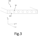
- the reinforced product 100 comprises at least one cable 50, in this case several cables 50, embedded in the elastomeric matrix 102.
- the elastomeric matrix 102 and the cables 50 are represented in a reference frame X, Y, Z in which the Y direction is the radial direction and the X and Z directions are the axial and circumferential directions.
- the reinforced product 100 comprises several cables 50 arranged side by side along the main direction X and extending parallel to each other within the reinforced product 100 and collectively embedded in the elastomeric matrix 102.
- the cable 50 is shown before the step 400 of bringing the external layer CE of the cable closer to the circle in which the internal layer CI of the cable is circumscribed.
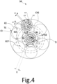
- the cable 50 is metallic and is of the multi-strand type with two cylindrical layers. Thus, it is understood that the layers of strands constituting the cable 50 are two in number, no more, no less.
- the cable 50 comprises an inner layer CI of the cable consisting of K ⁇ 1 inner strand(s) TI.
- the inner layer CI is surrounded by an elastomeric composition having a thickness G then forming the sheathed inner layer CIG.
- the outer layer CE is made up of L>1 outer strands TE wound around the sheathed inner layer CIG of the cable having a helix radius R2.
- R2 is here equal to 1.69 mm.
- the thickness G of the elastomeric composition is such that the ratio R2/Rt ranges from 1.02 to 1.25 with Rt being the helix radius of the theoretical outer layer CET obtained when the inner layer CI is directly in contact with the theoretical outer layer CET.
- R2 1.69 mm
- R2/Rt 1.06.
- the cable 50 is finally obtained by a method comprising a step 500 for bringing the outer layer CE of the cable closer to the circle in which the inner layer CI of the cable is circumscribed such that the ratio R2/Rt ranges from 1.00 to 1.10.
- Cable 50 also includes a fret F not shown consisting of a single fret wire.
- M 9.
- N 14.
- the intermediate layer C2 of each internal strand TI is desaturated and is incompletely unsaturated. Being desaturated, the inter-wire distance of the external layer of each internal strand is greater than or equal to 15 ⁇ m, more preferably greater than or equal to 35 ⁇ m and here equal to 43 ⁇ m.
- the sum Sl2 of the inter-wire distances l2 of the intermediate layer of each internal strand is greater than or equal to the diameter d2 of the intermediate wires of the intermediate layer of each internal strand.
- the outer layer C3 of each inner strand TI is desaturated and is incompletely unsaturated. Being desaturated, the inter-wire distance of the outer layer of each inner strand is greater than or equal to 15 ⁇ m, more preferably greater than or equal to 35 ⁇ m, even more preferably greater than or equal to 50 ⁇ m and here equal to 53 ⁇ m.
- the sum Sl3 of the inter-wire distances l3 of the outer layer of each inner strand is greater than or equal to the diameter d3 of the outer wires of the outer layer of each inner strand.
- Each inner, intermediate and outer wire of each inner strand TI has a diameter d1, d2 and d3 respectively.
- Each diameter of the inner wires d1, intermediate d2 and outer d3 of each inner strand TI ranges from 0.10 mm to 0.60 mm, preferably from 0.12 mm to 0.50 mm and more preferably from 0.14 mm to 0.42 mm.
- M' 9.
- N' 14.
- the intermediate layer C2' of each external strand TE is desaturated and is incompletely unsaturated. Being desaturated, the inter-wire distance of the external layer of each external strand is greater than or equal to 15 ⁇ m, more preferably greater than or equal to 35 ⁇ m and here equal to 43 ⁇ m.
- the sum Sl2' of the inter-wire distances l2' of the intermediate layer of each external strand is greater than or equal to the diameter d2' of the intermediate wires of the intermediate layer of each external strand.
- the outer layer C3 of each outer strand TE is desaturated and is incompletely unsaturated. Being desaturated, the inter-wire distance of the outer layer of each outer strand is greater than or equal to 15 ⁇ m, more preferably greater than or equal to 35 ⁇ m, even more preferably greater than or equal to 50 ⁇ m and here equal to 50 ⁇ m.
- the sum Sl3' of the inter-wire distances l3' of the outer layer of each outer strand is greater than or equal to the diameter d3' of the outer wires of the outer layer of each outer strand.
- Each inner, intermediate and outer wire of each outer strand TE has a diameter d1', d2' and d3' respectively.
- Each diameter of the inner wires d1', intermediate wires d2' and outer wires d3' of each outer strand TE ranges from 0.10 mm to 0.60 mm, preferably from 0.12 mm to 0.50 mm and more preferably from 0.14 mm to 0.42 mm.
- d1' 0.26mm
- the outer layer CE of the cable is desaturated.
- the average inter-strand distance E separating two adjacent outer strands TE is therefore greater than or equal to 20 ⁇ m.
- the average inter-strand distance E separating two adjacent outer strands TE is greater than or equal to 40 ⁇ m and more preferably 50 ⁇ m.
- the inter-strand distance E is equal to 170 ⁇ m.
- Each wire has a breaking strength, denoted Rm, such that 2500 ⁇ Rm ⁇ 3100 MPa.
- the steel of these wires is said to be of SHT ("Super High Tensile") grade.
- Other wires may be used, for example wires of lower grades, for example of NT ("Normal Tensile") or HT ("High Tensile”) grade, as well as wires of higher grades, for example of UT (“Ultra Tensile") or MT (“Mega Tensile”) grade.
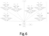
- K ⁇ 1 internal strands TI are assembled in a helix by cabling to form an internal layer CI of the cable.
- the internal layer CI is surrounded by an elastomeric composition having a thickness G to form a sheathed internal layer CIG, the thickness G of the elastomeric composition being such that the ratio R2/Rt ranges from 1.02 to 1.25 with Rt being the helix radius of the theoretical external layer CET obtained when the internal layer CI is directly in contact with the theoretical external layer CET.
- torque balancing is meant here, in a manner well known to those skilled in the art, the cancellation of residual torsional torques (or of the elastic return of torsion) exerted on each wire of the strand, in the intermediate layer as in the external layer.
- each strand is wound onto one or more receiving reels for storage before the subsequent operation of assembling by cabling the elementary strands to obtain the multi-strand cable.
- step 300 external strands TE are assembled in a helix L>1 by cabling around the internal layer CI of the cable.
- step 400 means 500 are used to bring the external layer CE of the cable closer to the circle in which the internal layer CIG of the cable is circumscribed such that the ratio R2/Rt ranges from 1.00 to 1.10.
- This step 400 is described with reference to the figure 7 .
- the means 500 used to bring the outer layer CE of the cable closer to the circle in which the inner layer CI of the cable is circumscribed are, for example, made up of two rows of rollers mounted facing each other but offset and between which the cable is passed. Each row contains between 6 and 8 rollers. One of the rows is movable and can be brought closer to the fixed row so that the cable undergoes a succession of bending. These rows of rollers can be fixed or movable around the axis of the cable.
- the cable undergoes a series of bends which allow its diameter to be reduced as illustrated in figure 7 .
- L is equal to the maximum number of external strands TE Lmax that can be arranged on the theoretical external layer CET having a helix radius Rt and L is such that the external layer CE is incompletely unsaturated.
- the thickness G of the sheath of elastomeric composition is strictly greater than 0 mm and preferably greater than or equal to 0.01 mm. and the thickness G is less than or equal to 0.80 mm, preferably less than or equal to 0.60 mm and more preferably less than or equal to 0.52 mm.
- G 0.08 mm.
- the elastomeric composition comprises a vulcanization system, a filler and a diene elastomer.
- elastomeric composition a conventional diene elastomer(s) composition for tires is used, based on natural rubber (peptized) and carbon black N330 (65 pce), further comprising the following usual additives: sulfur (7 pce), sulfenamide accelerator (1 pce), ZnO (8 pce), stearic acid (0.7 pce), antioxidant (1.5 pce), cobalt naphthenate (1.5 pce) (pce meaning parts by weight per hundred parts of elastomer); the E10 modulus of the elastomeric coating composition is approximately 10 MPa.
- the hoop F is wound at pitch pf in direction S around the assembly previously obtained.
- the cable is then incorporated by calendering into composite fabrics formed from a known composition based on natural rubber and carbon black as a reinforcing filler, conventionally used for the manufacture of crown reinforcements of radial tires.
- This composition essentially comprises, in addition to the elastomer and reinforcing filler (carbon black), an antioxidant, stearic acid, an extender oil, cobalt naphthenate as an adhesion promoter, finally a vulcanization system (sulfur, accelerator, ZnO).
- the composite fabrics reinforced by these cables comprise an elastomeric composition matrix formed by two thin layers of elastomeric composition which are superimposed on either side of the cables and which have a thickness ranging from 1 and 4 mm respectively.
- the calendering pitch (cable laying pitch in the elastomeric composition fabric) ranges from 4 mm to 8 mm.
- This test determines the longitudinal air permeability of the cables tested, by measuring the volume of air passing through a test piece under constant pressure for a given time.
- the principle of such a test is to demonstrate the effectiveness of the treatment of a cable to make it impermeable to air; it has been described for example in the ASTM D2692-98 standard.
- Such a test is carried out on cables from manufacturing and not aged.
- the raw cables are previously coated on the outside with an elastomeric composition called coating.
- a series of 10 cables arranged in parallel is placed between two layers or "skims" (two rectangles of 80 x 200 mm) of a diene elastomeric composition in the raw state, each skim having a thickness of 5 mm; the whole is then blocked in a mold, each of the cables being held under sufficient tension (for example 3 daN) to ensure its straightness when placed in the mold, using clamping modules; then vulcanization (baking) is carried out for approximately 8 hours at a temperature of approximately 110°C and under a pressure of 15 bar (rectangular piston of 80 x 200 mm). After which, the assembly is removed from the mold and 10 test pieces of cables thus coated are cut, in the form of parallelepipeds of dimensions 7x7x60 mm, for characterization.
- elastomeric coating composition a conventional diene elastomer(s) composition for tires, based on natural rubber (peptized) and carbon black N330 (65 pce), further comprising the following usual additives: sulfur (7 pce), sulfenamide accelerator (1 pce), ZnO (8 pce), stearic acid (0.7 pce), antioxidant (1.5 pce), cobalt naphthenate (1.5 pce) (pce meaning parts by weight per hundred parts of elastomer); the E10 modulus of the elastomeric coating composition is approximately 10 MPa.
- the test is carried out on a 6 cm length of cable, therefore coated by its surrounding elastomeric composition (or elastomeric coating composition) in the cured state, as follows: air is sent to the cable inlet, under a pressure of 1 bar, and the volume of air at the outlet is measured, using a flow meter (calibrated for example from 0 to 500 cm 3 /min).
- the cable sample is blocked in a compressed airtight seal (for example a dense foam or rubber seal) in such a way that only the quantity of air passing through the cable from one end to the other, along its longitudinal axis, is taken into account by the measurement; the tightness of the airtight seal itself is checked beforehand using a test piece of solid elastomeric composition, i.e. without cable.
- a compressed airtight seal for example a dense foam or rubber seal
- the average air flow rate measured (average over the 10 test pieces) is lower as the longitudinal impermeability of the cable is high. Since the measurement is made with an accuracy of ⁇ 0.2 cm 3 /min, measured values less than or equal to 0.2 cm 3 /min are considered zero; they correspond to a cable that can be described as airtight (totally airtight) along its axis (i.e., in its longitudinal direction).
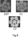
- Table 2 summarizes the characteristics of the comparative cables C1 and C2 and the state-of-the-art cable EDT (189.23).
- Cables C1 C2 EDT IT Q/M/N 4/9/14 4/9/14 3/9/15 d1/d2/d3 0.26/0.26/0.26 0.26/0.26/0.26 0.23/0.23/0.23 direction
- C1/p1 pitch (mm) Z/6 S/6.5 Z/6.5 direction
- the results of the permeability test are summarized in Table 3 below. respectively for the cable of the state of the art EDT, the comparative cables C1 and C2 and the cables according to the invention 50, 60 and 70.
- the comparative cable C1 is a version of the cable 189.23 of the EDT in which layers of wires are desaturated and the wire diameters are differentiated to improve the penetrability.
- the cable C2 is another version of the cable 189.23 of the EDT.
- the results of these tests are given on a base of 100.
- a result greater than 100 in one or other of these tests means that the cable tested has a greater impermeability than the control cable, here the control cable C1 compared to the cables C2, 50, 51, 60 and 70.
- the cables 50, 51, 60 and 70 according to the invention have a penetrability which is very clearly superior to that of the EDT cable and is clearly superior to that of the comparative cables C1 and C2, and this, solely because of the R2/Rt ratio in accordance with the invention. It is also noted on the figure 9 , that the central capillary is almost completely penetrated for cables 50, 51 and 70 while on the figure 8 that of the EDT cable and those of the comparative cables C1 and C2 are not, the dark areas being the areas where elastomeric composition is missing.
Landscapes
- Engineering & Computer Science (AREA)
- Mechanical Engineering (AREA)
- Ropes Or Cables (AREA)
- Tires In General (AREA)
Claims (15)
- Mehrlitziges Seil (50) mit zwei Lagen, umfassend:- eine innere Lage (CI) des Seils, die aus K ≥ 1 inneren Litze(n) (TI) besteht, wobei die oder jede innere Litze (TI) drei Lagen (C1, C2, C3) aufweist und Folgendes umfasst:- eine innere Lage (C1), die aus Q = 2, 3 oder 4 inneren Metalldrähten (F1) besteht,- eine mittlere Lage (C2), die aus M mittleren Metalldrähten (F2) mit einem Durchmesser d2 besteht, die um die innere Lage (C1) gewickelt sind, und- eine äußere Lage (C3), die aus N äußeren Metalldrähten (F3) mit einem Durchmesser d3 besteht, die um die mittlere Lage (C2) gewickelt sind,- eine äußere Lage (CE) des Seils, die aus L > 1 äußeren Litzen (TE) besteht, die um die innere Lage (CI) des Seils gewickelt sind, und einen Helixradius R2 aufweist, wobei jede äußere Litze (TE) drei Lagen (C1', C2', C3') aufweist und Folgendes umfasst:wobei:- eine innere Lage (C1'), die aus Q' = 2, 3 oder 4 inneren Metalldrähten (F1') besteht,- eine mittlere Lage (C2'), die aus M' mittleren Metalldrähten (F2') mit einem Durchmesser d2' besteht, die um die innere Lage (C1') gewickelt sind, und- eine äußere Lage (C3'), die aus N' äußeren Metalldrähten (F3') mit einem Durchmesser d3' besteht, die um die mittlere Lage (C2') gewickelt sind,- die mittlere Lage (C2) der oder jeder inneren Litze (TI) so entsättigt ist, dass die Summe SI2 der Abstände 12 zwischen den Drähten der mittleren Lage der oder jeder inneren Litze (TI) größer als oder gleich dem Durchmesser d2 ist;- die äußere Lage (C3) der oder jeder inneren Litze (TI) so entsättigt ist, dass die Summe SI3 der Abstände 13 zwischen den Drähten der äußeren Lage der oder jeder inneren Litze (TI) größer als oder gleich dem Durchmesser d3 ist;- die mittlere Lage (C2') der oder jeder äußeren Litze (TE) so entsättigt ist, dass die Summe SI2' der Abstände l2' zwischen den Drähten der mittleren Lage (C2') jeder äußeren Litze (TE) größer als oder gleich dem Durchmesser d2' ist;- die äußere Lage (C3') jeder äußeren Litze (TE) so entsättigt ist, dass die Summe SI3' der Abstände l3' zwischen den Drähten der äußeren Lage (C3') jeder äußeren Litze (TE) größer als oder gleich dem Durchmesser d3' ist; dadurch gekennzeichnet, dass:- das Seil (50) durch ein Verfahren erhalten wird, das Folgendes umfasst:- einen Schritt der Fertigung der ummantelten inneren Lage (CIG), bei dem die innere Lage (CI) mit einer Elastomerzusammensetzung, die eine Dicke G aufweist, dann mit einer äußeren Lage (CE) umgeben wird, wobei die Dicke G aus Elastomerzusammensetzung derart ist, dass das Verhältnis R2/Rt von 1,02 bis 1,25 reicht, wobei Rt der Helixradius der theoretischen äußeren Lage (CET) ist, der erhalten wird, wenn die innere Lage (CI) in direktem Kontakt mit der theoretischen äußeren Lage (CET) ist; und- einen Schritt (400) zum Annähern der äußeren Lage (CE) des Seils an den Kreis, in den die innere Lage (CI) des Seils eingeschrieben ist, sodass das Verhältnis R2/Rt von 1,00 bis 1,10 reicht.
- Seil (50) nach Anspruch 1, wobei die äußere Lage (CE) des Seils so gesättigt ist, dass der Zwischenlitzenabstand E der äußeren Litzen, der, über einen zur Hauptachse des Seils (50) senkrechten Abschnitt des Seils, als der kürzeste Abstand definiert ist, der im Durchschnitt die kreisförmigen Hüllen trennt, in die zwei benachbarte äußere Litzen (TE) einbeschrieben sind, strikt kleiner als 20 um ist.
- Seil (50) nach Anspruch 1, wobei L gleich der maximalen Anzahl von äußeren Litzen (TE) Lmax ist, die auf der theoretischen äußeren Lage (CET), die einen Helixradius Rt aufweist, angeordnet werden können, und L derart ist, dass die äußere Lage (CE) unvollständig ungesättigt ist, sodass es in der äußeren Lage nicht genügend Platz gibt, um mindestens eine (L+1)-te äußere Litze mit dem gleichen Durchmesser wie die L äußeren Litzen der äußeren Lage hinzuzufügen.
- Seil (50) nach einem der vorhergehenden Ansprüche, wobei die Dicke G des Mantels aus Elastomerzusammensetzung strikt größer als 0 mm und vorzugsweise größer als oder gleich 0,01 mm ist.
- Seil (50) nach einem der vorhergehenden Ansprüche, wobei die Dicke G des Mantels aus Elastomerzusammensetzung kleiner als oder gleich 0,80 mm, vorzugsweise kleiner als oder gleich 0,60 mm und noch bevorzugter kleiner als oder gleich 0,52 mm ist.
- Seil (50) nach einem der vorhergehenden Ansprüche, wobei die Elastomerzusammensetzung ein Elastomer umfasst, das aus der Gruppe gewählt ist, die aus den Polybutadienen, dem Naturkautschuk, den synthetischen Polyisoprenen, den Butadien-Copolymeren, den Isopren-Copolymeren und den Mischungen dieser Elastomere besteht.
- Seil (50) nach einem der vorhergehenden Ansprüche, wobei K = 1, 2, 3 oder 4, vorzugsweise K = 1, 2 oder 3 und noch bevorzugter K = 1 oder 3.
- Seil (50) nach einem der vorhergehenden Ansprüche, wobei L = 6, 7, 8, 9 oder 10, vorzugsweise L = 6, 7, 8 oder 9 und noch bevorzugter L = 6 oder 9.
- Seil (50) nach einem der vorhergehenden Ansprüche, wobei M = 7, 8, 9 oder 10 und vorzugsweise M = 7, 8 oder 9.
- Seil (50) nach einem der vorhergehenden Ansprüche, wobei M' = 7, 8, 9 oder 10 und vorzugsweise M' = 7, 8 oder 9.
- Seil (50) nach einem der vorhergehenden Ansprüche, wobei N = 12, 13, 14, 15 oder 16 und vorzugsweise N = 12, 13 oder 14.
- Seil (50) nach einem der vorhergehenden Ansprüche, wobei N' = 12, 13, 14, 15 oder 16 und vorzugsweise N' = 12, 13 oder 14.
- Verfahren zur Fertigung eines mehrlitzigen Seils (50) mit zwei Lagen, wobei:- in einem Schritt (100) K ≥ 1 innere Litze(n) (TI) durch Verseilen oder Verzwirnen spiralförmig angeordnet werden, um eine innere Lage (CI) des Seils zu bilden; wobei die oder jede innere Litze (TI) drei Lagen (C1, C2, C3) aufweist und Folgendes umfasst: eine innere Lage (C1), die aus Q = 2, 3 oder 4 inneren Metalldrähten (F1) besteht, eine mittlere Lage (C2), die aus M mittleren Metalldrähten (F2) mit einem Durchmesser d2 besteht, die um die innere Lage (C1) gewickelt sind, sodass die Summe SI2 der Abstände 12 zwischen den Drähten der mittleren Lage der oder jeder inneren Litze (TI) größer als oder gleich dem Durchmesser d2 ist, und eine äußere Lage (C3), die aus N äußeren Metalldrähten (F3) mit einem Durchmesser d3 besteht, die um die mittlere Lage (C2) gewickelt sind, sodass die Summe SI3 der Abstände 13 zwischen den Drähten der äußeren Lage der oder jeder inneren Litze (TI) größer als oder gleich dem Durchmesser d3 ist;- in einem Schritt (200) die innere Lage (CI) mit einer Elastomerzusammensetzung, die eine Dicke G aufweist, umgeben wird, um eine ummantelte innere Lage (CIG) zu bilden, wobei die Dicke G aus Elastomerzusammensetzung derart ist, dass das Verhältnis R2/Rt von 1,02 bis 1,25 reicht, wobei Rt der Helixradius der theoretischen äußeren Lage (CET) ist, der erhalten wird, wenn die innere Lage (CI) in direktem Kontakt mit der theoretischen äußeren Lage (CET) ist;- in einem Schritt (300) L > 1 äußere Litzen (TE) durch Verseilen oder Verzwirnen um die innere Lage (CI) des Seils spiralförmig angeordnet werden, wobei jede äußere Litze (TE) drei Lagen (C1', C2', C3') aufweist und Folgendes umfasst: eine innere Lage (C1'), die aus Q' = 2, 3 oder 4 inneren Metalldrähten (F1') besteht, eine mittlere Lage (C2'), die aus M' mittleren Metalldrähten (F2') mit einem Durchmesser d2' besteht, die um die innere Lage (C1') gewickelt sind, sodass die Summe SI2' der Abstände l2' zwischen den Drähten der mittleren Lage (C2') jeder äußeren Litze (TE) größer als oder gleich dem Durchmesser d2' ist, und eine äußere Lage (C3'), die aus N' äußeren Metalldrähten (F3') mit einem Durchmesser d3' besteht, die um die mittlere Lage (C2') gewickelt sind, sodass die Summe SI3' der Abstände l3' zwischen den Drähten der äußeren Lage (C3') jeder äußeren Litze (TE) größer als oder gleich dem Durchmesser d3' ist; dadurch gekennzeichnet, dass:- in einem Schritt (400) Mittel (500) zum Annähern der äußeren Lage (CE) des Seils an den Kreis, in den die innere Lage (CI) des Seils eingeschrieben ist, eingesetzt werden, sodass das Verhältnis R2/Rt von 1,00 bis 1,10 reicht.
- Verstärktes Produkt (100), dadurch gekennzeichnet, dass es eine Elastomermatrix (102) und mindestens ein Seil (50) nach einem der Ansprüche 1 bis 12 umfasst.
- Reifen (10), dadurch gekennzeichnet, dass er mindestens ein Seil (50) nach einem der Ansprüche 1 bis 12 oder ein verstärktes Produkt nach Anspruch 14 umfasst.
Applications Claiming Priority (2)
| Application Number | Priority Date | Filing Date | Title |
|---|---|---|---|
| FR2011344A FR3115799B1 (fr) | 2020-11-05 | 2020-11-05 | Câble multi-torons à deux couches avec couche interne gainée à pénétrabilité améliorée |
| PCT/FR2021/051861 WO2022096799A1 (fr) | 2020-11-05 | 2021-10-22 | Câble multi-torons à deux couches avec couche interne gainée à pénétrabilité améliorée |
Publications (2)
| Publication Number | Publication Date |
|---|---|
| EP4240897A1 EP4240897A1 (de) | 2023-09-13 |
| EP4240897B1 true EP4240897B1 (de) | 2024-10-02 |
Family
ID=74758916
Family Applications (1)
| Application Number | Title | Priority Date | Filing Date |
|---|---|---|---|
| EP21810406.5A Active EP4240897B1 (de) | 2020-11-05 | 2021-10-22 | Zweischichtiges mehrlitziges kabel mit einer internen beschichtung mit verbesserter durchlässigkeit |
Country Status (5)
| Country | Link |
|---|---|
| EP (1) | EP4240897B1 (de) |
| JP (1) | JP7769700B2 (de) |
| CN (1) | CN116490653A (de) |
| FR (1) | FR3115799B1 (de) |
| WO (1) | WO2022096799A1 (de) |
Family Cites Families (10)
| Publication number | Priority date | Publication date | Assignee | Title |
|---|---|---|---|---|
| FR2419182A1 (fr) | 1978-03-10 | 1979-10-05 | Michelin & Cie | Pneumatique a carcasse radiale, notamment pour engins de genie civil |
| FR2419181A1 (fr) | 1978-03-10 | 1979-10-05 | Michelin & Cie | Perfectionnements aux pneumatiques a carcasse radiale |
| WO2002044464A1 (en) * | 2000-12-01 | 2002-06-06 | N.V. Bekaert S.A. | Steel cord for reinforcing off-the-road tires and conveyor belts |
| JPWO2009011397A1 (ja) * | 2007-07-17 | 2010-09-24 | 株式会社ブリヂストン | コードおよびその製造方法並びに、コードおよびゴムの複合体 |
| FR2947574B1 (fr) * | 2009-07-03 | 2012-11-09 | Michelin Soc Tech | Cable multitorons dont les torons elementaires sont des cables a deux couches gommes in situ. |
| FR3022264A1 (fr) * | 2014-06-12 | 2015-12-18 | Michelin & Cie | Produit semi-fini comprenant un cable gomme in situ noye dans une composition de caoutchouc de calandrage |
| JP6545942B2 (ja) | 2014-10-01 | 2019-07-17 | 株式会社ブリヂストン | ゴム物品補強用スチールコードおよびそれを用いた空気入りタイヤ |
| FR3017885A1 (fr) * | 2015-06-16 | 2015-08-28 | Michelin & Cie | Cable metallique multi-torons |
| JP6936059B2 (ja) * | 2017-06-30 | 2021-09-15 | 株式会社ブリヂストン | ゴム物品補強用スチールコード |
| EP3810846B1 (de) * | 2018-06-20 | 2024-05-22 | Compagnie Generale Des Etablissements Michelin | Doppellagiges mehrfachstrangseil mit verbesserter durchlässigkeit |
-
2020
- 2020-11-05 FR FR2011344A patent/FR3115799B1/fr active Active
-
2021
- 2021-10-22 WO PCT/FR2021/051861 patent/WO2022096799A1/fr not_active Ceased
- 2021-10-22 CN CN202180071988.9A patent/CN116490653A/zh active Pending
- 2021-10-22 JP JP2023526259A patent/JP7769700B2/ja active Active
- 2021-10-22 EP EP21810406.5A patent/EP4240897B1/de active Active
Also Published As
| Publication number | Publication date |
|---|---|
| JP7769700B2 (ja) | 2025-11-13 |
| FR3115799A1 (fr) | 2022-05-06 |
| FR3115799B1 (fr) | 2022-10-14 |
| CN116490653A (zh) | 2023-07-25 |
| WO2022096799A1 (fr) | 2022-05-12 |
| EP4240897A1 (de) | 2023-09-13 |
| JP2023549704A (ja) | 2023-11-29 |
Similar Documents
| Publication | Publication Date | Title |
|---|---|---|
| EP3559337B1 (de) | Mehradriges kabel mit zwei schichten mit verbesserter durchlässigkeit | |
| EP3559338B1 (de) | Zweischichtiges mehradriges kabel mit verbesserter durchlässigkeit | |
| FR2999614A1 (fr) | Cable metallique a couches a haute penetrabilite | |
| EP4061996B1 (de) | Zweischichtiges mehradriges kabel mit einer verbesserten oberflächenenergie bis zum bruch | |
| EP4172406B1 (de) | Zweischichtiges mehradriges kabel mit verbesserter biegefestigkeit | |
| EP3810846B1 (de) | Doppellagiges mehrfachstrangseil mit verbesserter durchlässigkeit | |
| EP3810851B1 (de) | Doppellagiges mehrfachstrangseil mit verbesserter durchlässigkeit | |
| EP3810848B1 (de) | Doppellagiges mehrfachstrangseil mit verbesserter durchlässigkeit | |
| EP4240897B1 (de) | Zweischichtiges mehrlitziges kabel mit einer internen beschichtung mit verbesserter durchlässigkeit | |
| EP4172405B1 (de) | Zweischichtiges mehradriges kabel mit verbesserter biegefestigkeit | |
| EP4172408B1 (de) | Zweischichtiges mehradriges kabel mit verbesserter biegefestigkeit | |
| EP4172407B1 (de) | Zweischichtiges mehradriges kabel mit verbesserter biegefestigkeit | |
| EP3810847B1 (de) | Doppellagiges mehrfachstrangseil mit verbesserter durchlässigkeit | |
| EP3810850B1 (de) | Doppellagiges mehradriges kabel mit verbesserter durchdringbarkeit | |
| EP4058628B1 (de) | Zweischichtiges mehradriges kabel, das eine ummantelte innenschicht und verbesserte leistung aufweist | |
| EP3810849B1 (de) | Doppellagiges mehrfachstrangseil mit verbesserter durchlässigkeit | |
| EP4058627A1 (de) | Zweischichtiges mehradriges kabel, das eine ummantelte innenschicht und eine verbesserte durchdringungsfähigkeit aufweist | |
| FR3136788A1 (fr) | Câble multi-torons à deux couches de multi-torons | |
| FR3156459A1 (fr) | Câble multi-torons à deux couches de multi-torons | |
| WO2025008148A1 (fr) | Câble multi-torons à deux couches de multi-torons | |
| FR3150821A1 (fr) | Câble multi-torons à deux couches de multi-torons | |
| FR3136790A1 (fr) | Câble multi-torons à deux couches de multi-torons | |
| WO2014090999A2 (fr) | Câble métallique à couches cylindriques de structure 3+9+14 | |
| WO2014090998A2 (fr) | Câble métallique à couches cylindriques de structure 2+9+14 | |
| FR3136789A1 (fr) | Câble multi-torons à deux couches de multi-torons |
Legal Events
| Date | Code | Title | Description |
|---|---|---|---|
| STAA | Information on the status of an ep patent application or granted ep patent |
Free format text: STATUS: UNKNOWN |
|
| STAA | Information on the status of an ep patent application or granted ep patent |
Free format text: STATUS: THE INTERNATIONAL PUBLICATION HAS BEEN MADE |
|
| PUAI | Public reference made under article 153(3) epc to a published international application that has entered the european phase |
Free format text: ORIGINAL CODE: 0009012 |
|
| STAA | Information on the status of an ep patent application or granted ep patent |
Free format text: STATUS: REQUEST FOR EXAMINATION WAS MADE |
|
| 17P | Request for examination filed |
Effective date: 20230605 |
|
| AK | Designated contracting states |
Kind code of ref document: A1 Designated state(s): AL AT BE BG CH CY CZ DE DK EE ES FI FR GB GR HR HU IE IS IT LI LT LU LV MC MK MT NL NO PL PT RO RS SE SI SK SM TR |
|
| DAV | Request for validation of the european patent (deleted) | ||
| DAX | Request for extension of the european patent (deleted) | ||
| GRAP | Despatch of communication of intention to grant a patent |
Free format text: ORIGINAL CODE: EPIDOSNIGR1 |
|
| STAA | Information on the status of an ep patent application or granted ep patent |
Free format text: STATUS: GRANT OF PATENT IS INTENDED |
|
| INTG | Intention to grant announced |
Effective date: 20240523 |
|
| GRAS | Grant fee paid |
Free format text: ORIGINAL CODE: EPIDOSNIGR3 |
|
| GRAA | (expected) grant |
Free format text: ORIGINAL CODE: 0009210 |
|
| STAA | Information on the status of an ep patent application or granted ep patent |
Free format text: STATUS: THE PATENT HAS BEEN GRANTED |
|
| AK | Designated contracting states |
Kind code of ref document: B1 Designated state(s): AL AT BE BG CH CY CZ DE DK EE ES FI FR GB GR HR HU IE IS IT LI LT LU LV MC MK MT NL NO PL PT RO RS SE SI SK SM TR |
|
| REG | Reference to a national code |
Ref country code: GB Ref legal event code: FG4D Free format text: NOT ENGLISH |
|
| REG | Reference to a national code |
Ref country code: CH Ref legal event code: EP |
|
| REG | Reference to a national code |
Ref country code: DE Ref legal event code: R096 Ref document number: 602021019686 Country of ref document: DE |
|
| REG | Reference to a national code |
Ref country code: IE Ref legal event code: FG4D Free format text: LANGUAGE OF EP DOCUMENT: FRENCH |
|
| PGFP | Annual fee paid to national office [announced via postgrant information from national office to epo] |
Ref country code: DE Payment date: 20241021 Year of fee payment: 4 |
|
| PGFP | Annual fee paid to national office [announced via postgrant information from national office to epo] |
Ref country code: FR Payment date: 20241129 Year of fee payment: 4 |
|
| REG | Reference to a national code |
Ref country code: LT Ref legal event code: MG9D |
|
| REG | Reference to a national code |
Ref country code: NL Ref legal event code: MP Effective date: 20241002 |
|
| REG | Reference to a national code |
Ref country code: AT Ref legal event code: MK05 Ref document number: 1728581 Country of ref document: AT Kind code of ref document: T Effective date: 20241002 |
|
| PG25 | Lapsed in a contracting state [announced via postgrant information from national office to epo] |
Ref country code: NL Free format text: LAPSE BECAUSE OF FAILURE TO SUBMIT A TRANSLATION OF THE DESCRIPTION OR TO PAY THE FEE WITHIN THE PRESCRIBED TIME-LIMIT Effective date: 20241002 |
|
| PG25 | Lapsed in a contracting state [announced via postgrant information from national office to epo] |
Ref country code: NL Free format text: LAPSE BECAUSE OF FAILURE TO SUBMIT A TRANSLATION OF THE DESCRIPTION OR TO PAY THE FEE WITHIN THE PRESCRIBED TIME-LIMIT Effective date: 20241002 |
|
| PG25 | Lapsed in a contracting state [announced via postgrant information from national office to epo] |
Ref country code: HR Free format text: LAPSE BECAUSE OF FAILURE TO SUBMIT A TRANSLATION OF THE DESCRIPTION OR TO PAY THE FEE WITHIN THE PRESCRIBED TIME-LIMIT Effective date: 20241002 Ref country code: IS Free format text: LAPSE BECAUSE OF FAILURE TO SUBMIT A TRANSLATION OF THE DESCRIPTION OR TO PAY THE FEE WITHIN THE PRESCRIBED TIME-LIMIT Effective date: 20250202 Ref country code: PT Free format text: LAPSE BECAUSE OF FAILURE TO SUBMIT A TRANSLATION OF THE DESCRIPTION OR TO PAY THE FEE WITHIN THE PRESCRIBED TIME-LIMIT Effective date: 20250203 |
|
| PG25 | Lapsed in a contracting state [announced via postgrant information from national office to epo] |
Ref country code: FI Free format text: LAPSE BECAUSE OF FAILURE TO SUBMIT A TRANSLATION OF THE DESCRIPTION OR TO PAY THE FEE WITHIN THE PRESCRIBED TIME-LIMIT Effective date: 20241002 |
|
| PG25 | Lapsed in a contracting state [announced via postgrant information from national office to epo] |
Ref country code: BG Free format text: LAPSE BECAUSE OF FAILURE TO SUBMIT A TRANSLATION OF THE DESCRIPTION OR TO PAY THE FEE WITHIN THE PRESCRIBED TIME-LIMIT Effective date: 20241002 |
|
| PG25 | Lapsed in a contracting state [announced via postgrant information from national office to epo] |
Ref country code: ES Free format text: LAPSE BECAUSE OF FAILURE TO SUBMIT A TRANSLATION OF THE DESCRIPTION OR TO PAY THE FEE WITHIN THE PRESCRIBED TIME-LIMIT Effective date: 20241002 |
|
| PG25 | Lapsed in a contracting state [announced via postgrant information from national office to epo] |
Ref country code: NO Free format text: LAPSE BECAUSE OF FAILURE TO SUBMIT A TRANSLATION OF THE DESCRIPTION OR TO PAY THE FEE WITHIN THE PRESCRIBED TIME-LIMIT Effective date: 20250102 |
|
| PG25 | Lapsed in a contracting state [announced via postgrant information from national office to epo] |
Ref country code: LV Free format text: LAPSE BECAUSE OF FAILURE TO SUBMIT A TRANSLATION OF THE DESCRIPTION OR TO PAY THE FEE WITHIN THE PRESCRIBED TIME-LIMIT Effective date: 20241002 Ref country code: AT Free format text: LAPSE BECAUSE OF FAILURE TO SUBMIT A TRANSLATION OF THE DESCRIPTION OR TO PAY THE FEE WITHIN THE PRESCRIBED TIME-LIMIT Effective date: 20241002 Ref country code: GR Free format text: LAPSE BECAUSE OF FAILURE TO SUBMIT A TRANSLATION OF THE DESCRIPTION OR TO PAY THE FEE WITHIN THE PRESCRIBED TIME-LIMIT Effective date: 20250103 |
|
| PG25 | Lapsed in a contracting state [announced via postgrant information from national office to epo] |
Ref country code: PL Free format text: LAPSE BECAUSE OF FAILURE TO SUBMIT A TRANSLATION OF THE DESCRIPTION OR TO PAY THE FEE WITHIN THE PRESCRIBED TIME-LIMIT Effective date: 20241002 Ref country code: CZ Free format text: LAPSE BECAUSE OF FAILURE TO SUBMIT A TRANSLATION OF THE DESCRIPTION OR TO PAY THE FEE WITHIN THE PRESCRIBED TIME-LIMIT Effective date: 20241002 |
|
| PG25 | Lapsed in a contracting state [announced via postgrant information from national office to epo] |
Ref country code: RS Free format text: LAPSE BECAUSE OF FAILURE TO SUBMIT A TRANSLATION OF THE DESCRIPTION OR TO PAY THE FEE WITHIN THE PRESCRIBED TIME-LIMIT Effective date: 20250102 |
|
| REG | Reference to a national code |
Ref country code: CH Ref legal event code: PL |
|
| PG25 | Lapsed in a contracting state [announced via postgrant information from national office to epo] |
Ref country code: SM Free format text: LAPSE BECAUSE OF FAILURE TO SUBMIT A TRANSLATION OF THE DESCRIPTION OR TO PAY THE FEE WITHIN THE PRESCRIBED TIME-LIMIT Effective date: 20241002 |
|
| REG | Reference to a national code |
Ref country code: DE Ref legal event code: R097 Ref document number: 602021019686 Country of ref document: DE |
|
| PG25 | Lapsed in a contracting state [announced via postgrant information from national office to epo] |
Ref country code: MC Free format text: LAPSE BECAUSE OF FAILURE TO SUBMIT A TRANSLATION OF THE DESCRIPTION OR TO PAY THE FEE WITHIN THE PRESCRIBED TIME-LIMIT Effective date: 20241002 |
|
| PG25 | Lapsed in a contracting state [announced via postgrant information from national office to epo] |
Ref country code: DK Free format text: LAPSE BECAUSE OF FAILURE TO SUBMIT A TRANSLATION OF THE DESCRIPTION OR TO PAY THE FEE WITHIN THE PRESCRIBED TIME-LIMIT Effective date: 20241002 |
|
| PG25 | Lapsed in a contracting state [announced via postgrant information from national office to epo] |
Ref country code: BE Free format text: LAPSE BECAUSE OF NON-PAYMENT OF DUE FEES Effective date: 20241031 Ref country code: LU Free format text: LAPSE BECAUSE OF NON-PAYMENT OF DUE FEES Effective date: 20241022 |
|
| PG25 | Lapsed in a contracting state [announced via postgrant information from national office to epo] |
Ref country code: EE Free format text: LAPSE BECAUSE OF FAILURE TO SUBMIT A TRANSLATION OF THE DESCRIPTION OR TO PAY THE FEE WITHIN THE PRESCRIBED TIME-LIMIT Effective date: 20241002 |
|
| PG25 | Lapsed in a contracting state [announced via postgrant information from national office to epo] |
Ref country code: CH Free format text: LAPSE BECAUSE OF NON-PAYMENT OF DUE FEES Effective date: 20241031 |
|
| PG25 | Lapsed in a contracting state [announced via postgrant information from national office to epo] |
Ref country code: RO Free format text: LAPSE BECAUSE OF FAILURE TO SUBMIT A TRANSLATION OF THE DESCRIPTION OR TO PAY THE FEE WITHIN THE PRESCRIBED TIME-LIMIT Effective date: 20241002 |
|
| PG25 | Lapsed in a contracting state [announced via postgrant information from national office to epo] |
Ref country code: SK Free format text: LAPSE BECAUSE OF FAILURE TO SUBMIT A TRANSLATION OF THE DESCRIPTION OR TO PAY THE FEE WITHIN THE PRESCRIBED TIME-LIMIT Effective date: 20241002 |
|
| PG25 | Lapsed in a contracting state [announced via postgrant information from national office to epo] |
Ref country code: IT Free format text: LAPSE BECAUSE OF FAILURE TO SUBMIT A TRANSLATION OF THE DESCRIPTION OR TO PAY THE FEE WITHIN THE PRESCRIBED TIME-LIMIT Effective date: 20241002 |
|
| REG | Reference to a national code |
Ref country code: BE Ref legal event code: MM Effective date: 20241031 |
|
| PLBE | No opposition filed within time limit |
Free format text: ORIGINAL CODE: 0009261 |
|
| STAA | Information on the status of an ep patent application or granted ep patent |
Free format text: STATUS: NO OPPOSITION FILED WITHIN TIME LIMIT |
|
| PG25 | Lapsed in a contracting state [announced via postgrant information from national office to epo] |
Ref country code: SE Free format text: LAPSE BECAUSE OF FAILURE TO SUBMIT A TRANSLATION OF THE DESCRIPTION OR TO PAY THE FEE WITHIN THE PRESCRIBED TIME-LIMIT Effective date: 20241002 |
|
| 26N | No opposition filed |
Effective date: 20250703 |
|
| PG25 | Lapsed in a contracting state [announced via postgrant information from national office to epo] |
Ref country code: IE Free format text: LAPSE BECAUSE OF NON-PAYMENT OF DUE FEES Effective date: 20241022 |