EP4240653B1 - Verschliessvorrichtung zum verschliessen pharmazeutischer behältnisse - Google Patents
Verschliessvorrichtung zum verschliessen pharmazeutischer behältnisse Download PDFInfo
- Publication number
- EP4240653B1 EP4240653B1 EP21758639.5A EP21758639A EP4240653B1 EP 4240653 B1 EP4240653 B1 EP 4240653B1 EP 21758639 A EP21758639 A EP 21758639A EP 4240653 B1 EP4240653 B1 EP 4240653B1
- Authority
- EP
- European Patent Office
- Prior art keywords
- tool
- closing
- fluid
- module
- unit
- Prior art date
- Legal status (The legal status is an assumption and is not a legal conclusion. Google has not performed a legal analysis and makes no representation as to the accuracy of the status listed.)
- Active
Links
Images



Classifications
-
- A—HUMAN NECESSITIES
- A61—MEDICAL OR VETERINARY SCIENCE; HYGIENE
- A61L—METHODS OR APPARATUS FOR STERILISING MATERIALS OR OBJECTS IN GENERAL; DISINFECTION, STERILISATION OR DEODORISATION OF AIR; CHEMICAL ASPECTS OF BANDAGES, DRESSINGS, ABSORBENT PADS OR SURGICAL ARTICLES; MATERIALS FOR BANDAGES, DRESSINGS, ABSORBENT PADS OR SURGICAL ARTICLES
- A61L2/00—Disinfection or sterilisation of materials or objects, in general; Accessories therefor
- A61L2/02—Disinfection or sterilisation of materials or objects, in general; Accessories therefor using physical processes
- A61L2/022—Filtration
-
- B—PERFORMING OPERATIONS; TRANSPORTING
- B65—CONVEYING; PACKING; STORING; HANDLING THIN OR FILAMENTARY MATERIAL
- B65B—MACHINES, APPARATUS OR DEVICES FOR, OR METHODS OF, PACKAGING ARTICLES OR MATERIALS; UNPACKING
- B65B3/00—Packaging plastic material, semiliquids, liquids or mixed solids and liquids, in individual containers or receptacles, e.g. bags, sacks, boxes, cartons, cans, or jars
- B65B3/003—Filling medical containers such as ampoules, vials, syringes or the like
- B65B3/006—Related operations, e.g. scoring ampoules
-
- B—PERFORMING OPERATIONS; TRANSPORTING
- B65—CONVEYING; PACKING; STORING; HANDLING THIN OR FILAMENTARY MATERIAL
- B65B—MACHINES, APPARATUS OR DEVICES FOR, OR METHODS OF, PACKAGING ARTICLES OR MATERIALS; UNPACKING
- B65B55/00—Preserving, protecting or purifying packages or package contents in association with packaging
- B65B55/02—Sterilising, e.g. of complete packages
- B65B55/12—Sterilising contents prior to, or during, packaging
- B65B55/19—Sterilising contents prior to, or during, packaging by adding materials intended to remove free oxygen or to develop inhibitor gases, e.g. vapour phase inhibitors
-
- B—PERFORMING OPERATIONS; TRANSPORTING
- B65—CONVEYING; PACKING; STORING; HANDLING THIN OR FILAMENTARY MATERIAL
- B65B—MACHINES, APPARATUS OR DEVICES FOR, OR METHODS OF, PACKAGING ARTICLES OR MATERIALS; UNPACKING
- B65B7/00—Closing containers or receptacles after filling
- B65B7/16—Closing semi-rigid or rigid containers or receptacles not deformed by, or not taking-up shape of, contents, e.g. boxes or cartons
- B65B7/28—Closing semi-rigid or rigid containers or receptacles not deformed by, or not taking-up shape of, contents, e.g. boxes or cartons by applying separate preformed closures, e.g. lids, covers
- B65B7/2821—Closing semi-rigid or rigid containers or receptacles not deformed by, or not taking-up shape of, contents, e.g. boxes or cartons by applying separate preformed closures, e.g. lids, covers applying plugs or threadless stoppers
-
- A—HUMAN NECESSITIES
- A61—MEDICAL OR VETERINARY SCIENCE; HYGIENE
- A61L—METHODS OR APPARATUS FOR STERILISING MATERIALS OR OBJECTS IN GENERAL; DISINFECTION, STERILISATION OR DEODORISATION OF AIR; CHEMICAL ASPECTS OF BANDAGES, DRESSINGS, ABSORBENT PADS OR SURGICAL ARTICLES; MATERIALS FOR BANDAGES, DRESSINGS, ABSORBENT PADS OR SURGICAL ARTICLES
- A61L2103/00—Materials or objects being the target of disinfection or sterilisation
- A61L2103/05—Living organisms or biological materials
-
- A—HUMAN NECESSITIES
- A61—MEDICAL OR VETERINARY SCIENCE; HYGIENE
- A61L—METHODS OR APPARATUS FOR STERILISING MATERIALS OR OBJECTS IN GENERAL; DISINFECTION, STERILISATION OR DEODORISATION OF AIR; CHEMICAL ASPECTS OF BANDAGES, DRESSINGS, ABSORBENT PADS OR SURGICAL ARTICLES; MATERIALS FOR BANDAGES, DRESSINGS, ABSORBENT PADS OR SURGICAL ARTICLES
- A61L2202/00—Aspects relating to methods or apparatus for disinfecting or sterilising materials or objects
- A61L2202/10—Apparatus features
- A61L2202/18—Aseptic storing means
Definitions
- the invention relates to a closing device for closing pharmaceutical containers, with a closing tool for joining a closing element to a pharmaceutical container, with a fluid unit for supplying the container with at least one gaseous fluid, wherein the fluid unit has at least one filter.
- Closing devices of the type mentioned above are known from US 2011/094619 A1 and the US 5 641 004 A and are used in particular for sealing syringes, cartridges and vials. If such containers are filled with a highly reactive filling material, there is a risk that this filling material will react with oxygen. To avoid this, Partially filled containers are exposed to a protective gas, with the aim of ensuring that as little oxygen as possible remains in the container (i.e. above the filling level of the contents) after a closure element has been joined or placed on the container. In order to prevent foreign bodies from being transported into the container with the protective gas, the protective gas is passed through an appropriate filter. Other closure devices are available from the US 10 067 151 B2 and from the US 2020/338765 A1 known.
- the present invention is based on the object of specifying a closing device which enables simplified handling.
- the closing device provides a tool unit designed as a module.
- This module enables the closing tool, fluid unit and filter to be handled simultaneously.
- the module can be connected to or detached from a tool holder together with the above-mentioned components, using a coupling device.
- the assembly and disassembly process is limited to connecting the tool unit to the tool holder via the coupling device or detaching the tool unit from the tool holder.
- a tool unit removed from the tool holder can be handled, in particular cleaned, outside of a closing station, it being possible for individual components to be removed from the module in this state of the module being removed from the tool holder, for example the at least one filter.
- the tool holder can also be decontaminated, in particular by simply passing a decontaminant through it, for example hydrogen peroxide. Further sterilization is not necessary because the components of the tool unit are sterilized because the tool unit carries the at least one filter and because this filter, when the tool unit is coupled to the tool holder, prevents the introduction of germs into an area downstream of the at least one filter.
- a decontaminant for example hydrogen peroxide.
- the coupling device has a coupling element and a coupling element holder, which interact in a form-fitting manner when coupled to one another.
- One of the components, for example the coupling element is assigned to the tool holder, while the other component, for example the coupling element holder, is assigned to the tool unit.
- a reverse arrangement is also possible.
- the form-fitting of the aforementioned components of the coupling device enables a simple and precise connection of the tool unit to the tool holder, so that a possibly automated movement of the tool holder can be easily transferred to a corresponding movement of the tool unit.
- the tool holder comprises an actuating device for switching the coupling device between a locking state in which the module is connected to the tool holder and a release state in which the module can be detached from the tool holder.
- the control of the coupling device can be extended to the area of the tool holder. which simplifies the construction of the tool unit.
- the module has at least one fluid connection
- that the tool holder has at least one fluid supply device and that the at least one fluid connection and the fluid supply device are fluidly connected to one another in a state in which the module and the tool holder are connected to one another.
- the fluid unit of the tool unit is simultaneously connected to the fluid supply device without the need for further joining processes.
- the tool holder comprises an actuator for actuating the closing tool.
- the tool unit does not require its own actuating device for actuating the closing tool; thus, no control or energy supply needs to be provided for the tool unit. This leads to a further simplified structure of the tool unit and to further simplified cleaning.
- the fluid unit is designed to supply the container with at least two different gaseous fluids.
- the tool unit has at least two fluid connections which are supplied with at least two different gaseous fluids via the fluid supply device of the tool holder.
- the module comprises at least two filters, each of which interacts with one of the different gaseous fluids.
- These at least two filters can also be handled together with the module, i.e. they can be removed together from the closing device when the tool unit is dismantled from the tool holder and sterilized elsewhere, if necessary with dismantling of the filters.
- a combination of gaseous fluids in the form of a negative pressure gas and in the form of a protective gas is preferred.
- a negative pressure gas means a vacuum or partial vacuum.
- the protective gas is an inert gas, for example nitrogen.
- the tool holder is held on a robot arm. This enables the handling (in the sense of positioning) of the tool holder and - when the tool unit is coupled to the tool holder - also the handling of the tool unit and thus in particular also of the closing tool. It is possible for such a robot arm to delimit an interior in which parts of the fluid supply device, in particular fluid lines, possibly also valves or other devices, are arranged. In this way, the surfaces of the closing device that are exposed in the area of a closing station adjacent to a pharmaceutical container to be closed can be limited to the outer surface of the robot arm, the tool holder and the tool unit. This enables a closing station or the components of the closing device to be cleaned much more easily.
- the closing device has a handling device for handling the module.
- This handling device is a separate device from the aforementioned robot arm, which enables the positioning of the tool unit relative to the tool holder.
- This handling device can be, for example, a second robot arm.
- a closing device for closing pharmaceutical containers is designated in the drawing as a whole with the reference number 10.
- the closing device 10 is arranged in the area of a closing station of a filling plant and in particular arranged within a clean room.
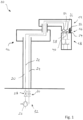
- the closing device 10 has a Figure 1 schematically illustrated robot arm 12 which holds a tool holder 14.
- the tool holder 14 can be repeatedly and detachably connected to a tool unit 18 via a coupling device 16.
- the robot arm 12 has an interior space 20 in which fluid lines 22, 24 for different gaseous fluids are arranged.
- the fluid line 22 is used to conduct vacuum.
- the fluid line 22 can be connected to a vacuum pump 26 using a first switching valve 28.
- a second switching valve 30 is used to introduce a protective gas, in particular nitrogen, into the fluid line 24 or to block such introduction.
- the components 20 to 30 together form a fluid supply device 32 which extends into an area of the tool holder 14 facing the coupling device 16.
- the tool holder 14 has respective supply connections 34 and 36, which can be coupled to corresponding fluid connections 38 and 40 of the tool unit 18.
- the structure of the tool holder 14, the coupling device 16 and the tool unit 18 is described below with reference to the Figures 2 to 4 explained.
- the Figure 2 a state in which the tool unit 18 is connected to the tool holder 14.
- the tool unit 18 serves to Figures 2 , 3 , 5 and 6 shown pharmaceutical container 68 by means of a Figures 5 and 6 shown closing tool 42.
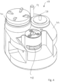
- the coupling device 16 comprises a coupling element 46, see Figure 3 , which is in a Figure 2 shown locking state of the coupling device 16 with a coupling element holder 48 of the tool unit 18, compare Figure 4 , cooperates.
- the coupling element 46 is designed, for example, as a bolt which cooperates with a coupling element receptacle 48 in the form of a groove.
- the coupling element 46 is preferably arranged on the tool holder 14 and can be actuated by means of an actuating device 50 which is only shown schematically. When the coupling element 46 is actuated, it is moved relative to the tool holder 14 and relative to the coupling element holder 48 so that the coupling device assumes a locking state (see Figure 2 ) or a release state, compare Figure 3 .
- the tool holder 14 further comprises a Figure 3 with a dash-dotted line indicated receiving bush 52, which serves to receive a pin 54 of the tool unit 18.
- the connection between the components 52 and 54 supports the above-explained positive Connection of the tool unit 18 and the tool holder 14 by means of the coupling device 16.
- the tool holder 14 further comprises a Figure 3 with dashed lines indicated actuator 56, which is movable along an actuator axis 58 and thus actuates an actuating surface 60 of the closing tool 42, compare Figures 4 , 5 and 6 .
- the tool unit 18 is designed as a module which has a housing 62.
- the housing 62 serves for the arrangement and positioning of the components described below.
- the housing 62 comprises in particular the components already described with reference to Figure 1 mentioned fluid connections 38 and 40 and the closing tool 42.
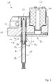
- respective filters 64 see Figure 5
- 66 see Figure 6 .
- a first filter 64 is designed as a sterile filter.
- the filter 64 prevents potentially toxic gases from an interior of a pharmaceutical container 68 to be sealed from entering the area of the fluid supply device 32 or an exterior area of the sealing device 10.
- the filter 64 is therefore assigned to the negative pressure gas or vacuum or partial vacuum of the fluid supply device 32.
- a second filter 66 is assigned to the protective gas, for example nitrogen.
- the filter 66 prevents Foreign bodies from the fluid supply device 32 are introduced into the container 68.
- the first filter 64 is associated with a fluid path that leads via a first branch line 70 to an annular collecting chamber 72, see Figure 5 .
- a corresponding second branch line 74 is provided, which also opens into the collecting chamber 72, compare Figure 6 .
- the collecting chamber 72 extends in a ring shape around a plug tappet 44 of the closing tool 42.
- the plug tappet 44 is subjected to force by means of a compression spring 76, so that the plug tappet 44 is held in a basic position in the direction of the tool holder 14, so that the actuating surface 60 - accordingly Figure 4 - is arranged further away from the container 68 to be closed than in a Figures 5 and 6
- the actuator 56 presses on the actuation surface 60 so that the actuation plunger 44 presses a closure element 78, for example a plug, into an open end region of the container 68.
- the container 68 is designed, for example, in the form of a syringe, a carpule or a vial.
- the container 68 is preferably held on a holder (not shown in the drawing) in such a way that an initially open and to-be-closed end region of the container 68 points upwards with respect to the direction of gravity.
- the container 68 serves to hold a pharmaceutical filling material 80, which has an upper filling level 82.
- a space 84 remains between the filling level 82 and an upper, initially open boundary of the container 68.
- the closure element 78 is then initially arranged at the level of a sealing nozzle 86, which is connected at one end to the tool unit 18 and at the other end rests against an end flange 88 of the container 68.
- the sealing nozzle 86 is hollow on the inside and is dimensioned such that the closure element 78 has a smaller diameter, so that gaseous fluid from the collecting space 72 around the closure element 78 can be introduced into and removed from the space 84.
- the space 84 can be subjected to negative pressure by actuating the vacuum pump 76 and the first switching valve 78.
- Protective gas can then be introduced into the space 84 by actuating the second switching valve 30.
- stopper tappet can be joined to another closure element 78 and another partially filled container 68 can be provided and the processes described above can be repeated until the filling and closing of a batch of filling material is completed.
- This fluid unit 90 comprises in particular the collecting space 72 and fluid line areas, in particular in the form of the branch lines 70, 74.
- the tool unit 18 can be handled as a module.
- This module comprises the above-mentioned fluid unit 90, the filters 64 and 66 as well as the closing tool 42 and a part of the coupling device 16.
- the unit shown can be handled as a module, i.e. as a whole, and connected to the tool holder 14 or removed from it for sterilization in preparation for a subsequent batch.
- a further handling device (not shown) can be used, for example in the form of a second robot arm.
Landscapes
- Mechanical Engineering (AREA)
- Engineering & Computer Science (AREA)
- Health & Medical Sciences (AREA)
- Veterinary Medicine (AREA)
- General Health & Medical Sciences (AREA)
- Public Health (AREA)
- Animal Behavior & Ethology (AREA)
- Life Sciences & Earth Sciences (AREA)
- Epidemiology (AREA)
- Medical Preparation Storing Or Oral Administration Devices (AREA)
- Basic Packing Technique (AREA)
- Apparatus For Disinfection Or Sterilisation (AREA)
- Filling Of Jars Or Cans And Processes For Cleaning And Sealing Jars (AREA)
Description
- Die Erfindung betrifft eine Verschließvorrichtung zum Verschließen pharmazeutischer Behältnisse, mit einem Verschließwerkzeug zum Fügen eines Verschlusselements mit einem pharmazeutischen Behältnis, mit einer Fluideinheit zur Beaufschlagung des Behältnisses mit mindestens einem gasförmigen Fluid, wobei die Fluideinheit mindestens einen Filter aufweist.
- Verschließvorrichtungen der vorstehend genannten Art sind aus der
US 2011/094619 A1 und derUS 5 641 004 A bekannt und werden insbesondere zum Verschließen von Spritzen, Karpulen und Vials verwendet. Wenn solche Behältnisse mit einem hochreaktiven Füllgut gefüllt sind, besteht die Gefahr, dass dieses Füllgut mit Sauerstoff reagiert. Um dies zu vermeiden, werden teilgefüllte Behältnisse mit einem Schutzgas beaufschlagt, verbunden mit dem Ziel, dass nach dem Fügen oder Aufsetzen eines Verschlusselements auf das Behältnis möglichst wenig Sauerstoff in dem Behältnis (also oberhalb des Füllspiegels des Füllguts) verbleibt. Um zu vermeiden, dass Fremdkörper mit dem Schutzgas in das Behältnis hinein transportiert werden, wird das Schutzgas durch einen entsprechenden Filter geleitet. Weitere Verschließvorrichtungen sind aus derUS 10 067 151 B2 US 2020/338765 A1 bekannt. - Es ist auch bekannt, den Raum des Behältnisses oberhalb des Füllspiegels des Füllguts mit Unterdruck zu beaufschlagen, beispielsweise um die Einleitung des Schutzgases zu vereinfachen. Sofern es sich bei dem Füllgut um einen toxischen Wirkstoff handelt, ist es für den Fall des Einsatzes eines Unterdruckgases oder eines Teilvakuums bekannt, einen behälternahen Filter zu verwenden, der verhindert, dass toxische Gase aus dem Behälter heraus in einen Außenbereich, also beispielsweise in dem Bereich einer Unterdruckversorgung, gelangen.
- Um unter den vorstehend genannten Bedingungen das Einbringen von Keimen in das Behältnis während des Schließvorgangs zu vermeiden, ist es erforderlich, Fluidleitungen der Fluideinheit und den mindestens einen Filter zunächst außerhalb einer Verschließstation zu sterilisieren. Die sterilisierten Teile werden dann in einen Reinraumbereich einer Verschließstation eingebracht und dort mittels Handschuheingriff montiert. Dieser Vorgang muss bei der Umstellung auf ein neues Füllgut jedes Mal wiederholt werden, insbesondere, wenn zuvor toxisches Füllgut verarbeitet wurde.
- Der Ausbau, die Sterilisierung und der Einbau einer Vielzahl von Teilen (Fluidleitungen, Filter) über einen Handschuheingriff ist zeitaufwändig und fehleranfällig. Auch unter Gesichtspunkten des Arbeitsschutzes ist das vorstehend erläuterte und im Stand der Technik praktizierte Vorgehen nicht optimal.
- Hiervon ausgehend liegt der vorliegenden Erfindung die Aufgabe zugrunde, eine Verschließvorrichtung anzugeben, welche eine vereinfachte Handhabung ermöglicht.
- Diese Aufgabe durch eine Verschließvorrichtung mit den Merkmalen des Patentanspruchs 1 gelöst.
- Bei der erfindungsgemäßen Verschließvorrichtung ist eine als Modul ausgebildete Werkzeugeinheit vorgesehen. Dieses Modul ermöglicht die gleichzeitige Handhabung von Verschließwerkzeug, Fluideinheit und Filter. Das Modul kann gemeinsam mit den vorstehend genannten Bauteilen an eine Werkzeugaufnahme angeschlossen oder von dieser gelöst werden, und zwar mittels einer Kopplungseinrichtung. Mit anderen Worten: Der Montage- und Demontagevorgang beschränkt sich darauf, die Werkzeugeinheit über die Kopplungseinrichtung mit der Werkzeugaufnahme zu verbinden bzw. die Werkzeugeinheit von der Werkzeugaufnahme zu lösen. Eine von der Werkzeugaufnahme entfernte Werkzeugeinheit kann außerhalb einer Verschließstation gehandhabt, insbesondere gereinigt werden, wobei es möglich ist, dass in diesem von der Werkzeugaufnahme entfernten Zustand des Moduls einzelne Bauteile von dem Modul entfernt werden, beispielsweise der mindestens eine Filter.
- Die Werkzeugaufnahme kann ebenfalls dekontaminiert werden, insbesondere durch einfache Durchströmung mit einem Dekontaminationsmittel, beispielsweise mit Wasserstoffperoxid. Eine weitere Sterilisierung ist nicht erforderlich, da die Bauteile der Werkzeugeinheit sterilisiert werden, da die Werkzeugeinheit den mindestens einen Filter trägt und da dieser Filter im gekoppelten Zustand der Werkzeugeinheit mit der Werkzeugaufnahme das Einbringen von Keimen in einen Bereich fluidabwärts des mindestens einen Filters verhindert.
- Bei einer bevorzugten Ausführungsform weist die Kopplungseinrichtung ein Kopplungselement und eine Kopplungselementaufnahme auf, welche in einem miteinander gekoppelten Zustand formschlüssig zusammenwirken. Eines der Bauteile, beispielsweise das Kopplungselement, ist der Werkzeugaufnahme zugeordnet, während das andere Bauteil, beispielsweise die Kopplungselementaufnahme, der Werkzeugeinheit zugeordnet ist. Auch eine umgekehrte Anordnung ist möglich. Der Formschluss der genannten Bauteile der Kopplungseinrichtung ermöglicht eine einfache und genaue Verbindung der Werkzeugeinheit mit der Werkzeugaufnahme, sodass eine ggf. automatisierte Bewegung der Werkzeugaufnahme in einfacher Weise auf eine entsprechende Bewegung der Werkzeugeinheit übertragbar ist.
- Bevorzugt ist es ferner, dass die Werkzeugaufnahme eine Betätigungseinrichtung zum Schalten der Kopplungseinrichtung zwischen einem Sperrzustand, in welchem das Modul mit der Werkzeugaufnahme verbunden ist, und einem Freigabezustand, in welchem das Modul von der Werkzeugaufnahme lösbar ist, umfasst. Auf diese Weise kann die Ansteuerung der Kopplungseinrichtung in den Bereich der Werkzeugaufnahme hinein verlagert werden, wodurch der Aufbau der Werkzeugeinheit vereinfacht wird.
- Bevorzugt ist es ferner, dass das Modul mindestens einen Fluidanschluss aufweist, dass die Werkzeugaufnahme mindestens eine Fluidversorgungseinrichtung aufweist und dass der mindestens eine Fluidanschluss und die Fluidversorgungseinrichtung in einem Zustand, in welchem das Modul und die Werkzeugaufnahme miteinander verbunden sind, miteinander fluidwirksam verbunden sind. Mit anderen Worten: Durch die Ankopplung der Werkzeugeinheit an die Werkzeugaufnahme wird die Fluideinheit der Werkzeugeinheit gleichzeitig mit der Fluidversorgungseinrichtung verbunden, ohne dass es weiterer Fügevorgänge bedarf.
- Es ist außerdem bevorzugt, dass die Werkzeugaufnahme einen Aktor zur Betätigung des Verschließwerkzeugs umfasst. Dies hat den Vorteil, dass die Werkzeugeinheit keine eigene Betätigungseinrichtung zur Betätigung des Verschließwerkzeugs benötigt; somit muss also auch keine Steuerung oder Energieversorgung für die Werkzeugeinheit bereitgestellt werden. Dies führt zu einem weiter vereinfachten Aufbau der Werkzeugeinheit und zu einer weiter vereinfachten Reinigbarkeit.
- Erfindungsgemäß ist die Fluideinheit zur Beaufschlagung des Behältnisses mit mindesten zwei unterschiedlichen gasförmigen Fluiden ausgebildet. Dies bedeutet, dass die Werkzeugeinheit mindestens zwei Fluidanschlüsse aufweist, welche über die Fluidversorgungseinrichtung der Werkzeugaufnahme mit mindestens zwei unterschiedlichen gasförmigen Fluiden versorgt werden.
- Erfindungsgemäß ist ferner vorgesehen, dass das Modul mindestens zwei Filter umfasst, die mit jeweils einem der unterschiedlichen gasförmigen Fluide zusammenwirken. Auch diese mindestens zwei Filter können gemeinsam mit dem Modul gehandhabt werden, also gemeinsam bei Demontage der Werkzeugeinheit von der Werkzeugaufnahme von der Verschließvorrichtung entfernt und anderenorts, ggf. mit Demontage der Filter, sterilisiert werden.
- Bevorzugt ist eine Kombination von gasförmigen Fluiden in Form eines Unterdruckgases und in Form eines Schutzgases. Mit einem Unterdruckgas ist ein Vakuum oder Teilvakuum gemeint. Das Schutzgas ist ein Inertgas, beispielsweise Stickstoff.
- Bevorzugt ist es ferner, wenn die Werkzeugaufnahme an einem Roboterarm gehalten ist. Dieser ermöglicht die Handhabung (im Sinne einer Positionierung) der Werkzeugaufnahme und - bei Kopplung der Werkzeugeinheit mit der Werkzeugaufnahme - auch die Handhabung der Werkzeugeinheit und somit insbesondere auch des Verschließwerkzeugs. Es ist möglich, dass ein solcher Roboterarm einen Innenraum begrenzt, in welchem Teile der Fluidversorgungseinrichtung, also insbesondere Fluidleitungen, ggf. auch Ventile oder weitere Einrichtungen, angeordnet sind. Somit können die im Bereich einer Verschließstation benachbart zu einem zu verschließenden pharmazeutischen Behältnis freiliegenden Oberflächen der Verschließvorrichtung auf die Außenfläche des Roboterarms, der Werkzeugaufnahme und der Werkzeugeinheit beschränkt werden. Dies ermöglicht eine stark vereinfachte Reinigung einer Verschließstation bzw. der Bauteile der Verschließvorrichtung.
- Ferner ist es bevorzugt, wenn die Verschließvorrichtung eine Handhabungseinrichtung zur Handhabung des Moduls aufweist. Bei dieser Handhabungseinrichtung handelt es sich um eine zu dem vorstehend genannten Roboterarm separate Einrichtung, welche die Positionierung der Werkzeugeinheit relativ zu der Werkzeugaufnahme ermöglicht. Bei dieser Handhabungseinrichtung kann es sich beispielsweise um einen zweiten Roboterarm handeln.
- Weitere Merkmale und Vorteile der Erfindung sind Gegenstand der nachfolgenden Beschreibung und der zeichnerischen Darstellung eines bevorzugten Ausführungsbeispiels.
- In der Zeichnung zeigt
- Fig. 1
- eine schematische Ansicht einer Ausführungsform einer Verschließvorrichtung;
- Fig. 2
- eine perspektivische Ansicht einer Werkzeugaufnahme und einer Werkzeugeinheit der Verschließvorrichtung gemäß
Fig. 1 , in einem miteinander gekoppelten Zustand; - Fig. 3
- eine der
Fig. 2 entsprechende Ansicht, in einem voneinander entkoppelten Zustand der Werkzeugaufnahme und der Werkzeugeinheit; - Fig. 4
- eine perspektivische Ansicht der Werkzeugeinheit;
- Fig. 5
- eine geschnittene Ansicht der Werkzeugeinheit längs einer ersten Schnittebene; und
- Fig. 6
- eine geschnittene Ansicht der Werkzeugeinheit längs einer zu der ersten Schnittebene winklig versetzten zweiten Schnittebene.
- Eine Verschließvorrichtung zum Verschließen pharmazeutischer Behältnisse ist in der Zeichnung insgesamt mit dem Bezugszeichen 10 bezeichnet. Die Verschließvorrichtung 10 ist im Bereich einer Verschließstation einer Abfüllanlage angeordnet und insbesondere innerhalb eines Reinraums angeordnet. Die Verschließvorrichtung 10 weist einen in
Figur 1 schematisch dargestellten Roboterarm 12 auf, der eine Werkzeugaufnahme 14 hält. Die Werkzeugaufnahme 14 ist über eine Kopplungseinrichtung 16 wiederholbar lösbar mit einer Werkzeugeinheit 18 verbindbar. - Der Roboterarm 12 weist einen Innenraum 20 auf, in welchem Fluidleitungen 22, 24 für unterschiedliche gasförmige Fluide angeordnet sind. Die Fluidleitung 22 dient zur Leitung von Vakuum. Zu diesem Zweck ist die Fluidleitung 22 mit einer Vakuumpumpe 26 verbindbar, und zwar unter Verwendung eines ersten Schaltventils 28. Ein zweites Schaltventil 30 dient dazu, ein Schutzgas, insbesondere Stickstoff, in die Fluidleitung 24 einzuleiten oder eine solche Einleitung zu sperren. Die Bauteile 20 bis 30 bilden gemeinsam eine Fluidversorgungseinrichtung 32, welche sich bis in einen der Kopplungseinrichtung 16 zugewandten Bereich der Werkzeugaufnahme 14 hinein erstreckt. Dort weist die Werkzeugaufnahme 14 jeweilige Versorgungsanschlüsse 34 bzw. 36 auf, die mit entsprechenden Fluidanschlüssen 38 bzw. 40 der Werkzeugeinheit 18 koppelbar sind.
- Der Aufbau der Werkzeugaufnahme 14, der Kopplungseinrichtung 16 und der Werkzeugeinheit 18 wird nachfolgend unter Bezugnahme auf die
Figuren 2 bis 4 erläutert. Dabei zeigt dieFigur 2 einen Zustand, in welchem die Werkzeugeinheit 18 mit der Werkzeugaufnahme 14 verbunden ist. Die Werkzeugeinheit 18 dient dazu, ein in denFiguren 2 ,3 ,5 und6 dargestelltes pharmazeutisches Behältnis 68 mittels eines in denFiguren 5 und6 dargestellten Verschließwerkzeugs 42 zu verschließen. - Die Kopplungseinrichtung 16 umfasst ein Kopplungselement 46, vergleiche
Figur 3 , welches in einem inFigur 2 dargestellten Sperrzustand der Kopplungseinrichtung 16 mit einer Kopplungselementaufnahme 48 der Werkzeugeinheit 18, vergleicheFigur 4 , zusammenwirkt. Das Kopplungselement 46 ist beispielsweise als Bolzen ausgebildet, der mit einer Kopplungselementaufnahme 48 in Form einer Nut zusammenwirkt. - Das Kopplungselement 46 ist vorzugsweise an der Werkzeugaufnahme 14 angeordnet und mittels einer nur schematisch dargestellten Betätigungseinrichtung 50 betätigbar. Bei einer Betätigung des Kopplungselements 46 wird dieses relativ zu der Werkzeugaufnahme 14 und relativ zu der Kopplungselementaufnahme 48 bewegt, sodass die Kopplungseinrichtung einen Sperrzustand (vergleiche
Figur 2 ) einnimmt oder einen Freigabezustand, vergleicheFigur 3 . - Die Werkzeugaufnahme 14 umfasst ferner eine in
Figur 3 mit einer strichpunktierten Linie angedeuteten Aufnahmebuchse 52, welche zur Aufnahme eines Stifts 54 der Werkzeugeinheit 18 dient. Die Verbindung zwischen den Bauteilen 52 und 54 unterstützt die vorstehend erläuterte formschlüssige Verbindung der Werkzeugeinheit 18 und der Werkzeugaufnahme 14 mittels der Kopplungseinrichtung 16. - Die Werkzeugaufnahme 14 umfasst ferner einen in
Figur 3 mit gestrichelten Linien angedeuteten Aktor 56, der längs einer Aktorachse 58 bewegbar ist und somit eine Betätigungsfläche 60 des Schließwerkzeugs 42 betätigt, vergleicheFiguren 4 ,5 und6 . - Der weitere Aufbau der Werkzeugeinheit 18 wird nachfolgend unter Bezugnahme auf die
Figuren 4 ,5 und6 beschrieben. - Die Werkzeugeinheit 18 ist als Modul ausgebildet, welches ein Gehäuse 62 aufweist. Das Gehäuse 62 dient zur Anordnung und Positionierung nachfolgend beschriebener Bauteile. Das Gehäuse 62 umfasst insbesondere die bereits unter Bezugnahme auf
Figur 1 genannten Fluidanschlüsse 38 und 40 sowie das Verschließwerkzeug 42. Ferner sind, bezogen auf die Fluidversorgungseinrichtung 32 stromabwärts der Fluidanschlüsse 38 und 40, jeweilige Filter 64 (vergleicheFigur 5 ) und 66 (vergleicheFigur 6 ) vorgesehen. - Ein erster Filter 64 ist als Sterilfilter ausgebildet. Mit dem Filter 64 wird vermieden, dass ggf. toxische Gase aus einem Innenraum eines zu verschließenden, pharmazeutischen Behälters 68 in den Bereich der Fluidversorgungseinrichtung 32 oder in einen Außenbereich der Verschließvorrichtung 10 gelangen. Der Filter 64 ist also dem Unterdruckgas bzw. Vakuum oder Teilvakuum der Fluidversorgungseinrichtung 32 zugeordnet.
- Ein zweiter Filter 66 ist dem Schutzgas, also beispielsweise Stickstoff, zugeordnet. Der Filter 66 verhindert, dass Fremdkörper aus der Fluidversorgungseinrichtung 32 in das Behältnis 68 hinein eingebracht werden.
- Der erste Filter 64 ist einem Fluidpfad zugeordnet, der über eine erste Stichleitung 70 zu einem ringförmigen Sammelraum 72 führt, vergleiche
Figur 5 . Für ein dem zweiten Filter 66 zugeleitetes Schutzgas ist eine entsprechende, zweite Stichleitung 74 vorgesehen, welche ebenfalls an dem Sammelraum 72 mündet, vergleicheFigur 6 . - Der Sammelraum 72 erstreckt sich ringförmig um einen Stopfenstößel 44 des Verschließwerkzeugs 42 herum. Der Stopfenstößel 44 ist mittels einer Druckfeder 76 kraftbeaufschlagt, sodass der Stopfenstößel 44 in einer Grundstellung in Richtung der Werkzeugaufnahme 14 gehalten ist, sodass die Betätigungsfläche 60 - entsprechend
Figur 4 - weiter von dem zu verschließenden Behältnis 68 entfernt angeordnet ist, als in einem in denFiguren 5 und6 dargestellten Betätigungszustand. In diesem Betätigungszustand drückt der Aktor 56 auf die Betätigungsfläche 60, sodass der Betätigungsstößel 44 ein Verschlusselement 78, beispielsweise einen Stopfen, in einen offenen Endbereich des Behältnisses 68 hineindrückt. - Das Behältnis 68 ist beispielsweise in Form einer Spritze, einer Karpule oder eines Vials ausgebildet. Das Behältnis 68 ist vorzugweise an (in der Zeichnung nicht dargestellten) Halter so gehalten, dass ein zunächst offener und zu verschließender Endbereich des Behältnisses 68 bezogen auf die Richtung der Schwerkraft nach oben weist.
- Das Behältnis 68 dient zur Aufnahme eines pharmazeutischen Füllguts 80, das einen oberen Füllspiegel 82 aufweist. Zwischen dem Füllspiegel 82 und einer oberen, zunächst offenen Begrenzung des Behältnisses 68 verbleibt ein Raum 84. Vor Einführung des Verschlusselements 78 in den zunächst offenen Endbereich des Behältnisses 68 ist das Verschlusselement 78 bereits an dem Stopfenstößel 44 aufgenommen. Der Stopfenstößel 44 befindet sich aber zunächst noch in seiner oberen Grundstellung (vgl.
Fig. 4 ), in welcher die Betätigungsfläche 60 weiter oben angeordnet ist, sodass das Verschlusselement 68 zunächst noch außerhalb des Behältnisses 68 angeordnet ist. - Das Verschlusselement 78 ist dann zunächst noch auf Höhe eines Abdichtstutzens 86 angeordnet, der einenends mit der Werkzeugeinheit 18 verbunden und anderenends an einem endseitigen Flansch 88 des Behältnisses 68 anliegt. Der Abdichtstutzen 86 ist innen hohl und so bemessen, dass das Verschlusselement 78 einen kleineren Durchmesser aufweist, sodass gasförmiges Fluid aus dem Sammelraum 72 um das Verschlusselement 78 herum in den Raum 84 ein- und ausführbar ist. In diesem Zustand kann der Raum 84 unter Betätigung der Vakuumpumpe 76 und des ersten Schaltventils 78 mit Unterdruck beaufschlagt werden. Anschließend kann unter Betätigung des zweiten Schaltventils 30 Schutzgas in den Raum 84 eingeführt werden. Die vorstehend genannten Vorgänge können wiederholt werden, bis der Raum 84 möglichst sauerstoffarm ist und das Verschlusselement 78 durch Betätigung des Stopfenstößels 44 in das Behältnis 68 eingeführt werden kann, sodass das Behältnis 68 verschlossen wird. Das Verschlusselement 78 verbleibt an dem Behältnis 68.
- Anschließend kann der Stopfenstößel mit einem weiteren Verschlusselement 78 gefügt und ein weiteres teilgefülltes Behältnis 68 bereitgestellt werden und die vorstehend beschriebenen Vorgänge wiederholt werden, bis die Abfüllung und das Verschließen einer Füllgutcharge abgeschlossen ist.
- Die Bereiche der Werkzeugeinheit 18, welche bezogen auf die Fluidversorgungseinrichtung 32 stromabwärts der Filter 64 und 66, also dem Behältnis 68 zugewandt sind, werden insgesamt als Fluideinheit 90 bezeichnet. Diese Fluideinheit 90 umfasst insbesondere den Sammelraum 72 und Fluidleitungsbereiche, insbesondere in Form der Stichleitungen 70, 74.
- Wie insbesondere aus
Figur 3 ersichtlich, kann die Werkzeugeinheit 18 insgesamt als Modul gehandhabt werden. Dieses Modul umfasst die vorstehend genannte Fluideinheit 90, die Filter 64 und 66 sowie das Verschließwerkzeug 42 und einen Teil der Kopplungseinrichtung 16. Diese, inFigur 4 dargestellte Einheit, kann als Modul, also als Ganzes gehandhabt werden und mit der Werkzeugaufnahme 14 verbunden bzw. von dieser zwecks Sterilisierung zur Vorbereitung einer Folgecharge entfernt werden. Für diese Fügevorgänge kann eine (nicht dargestellte) weitere Handhabungseinrichtung verwendet werden, bspw. in Form eines zweiten Roboterarms.
Claims (8)
- Verschließvorrichtung (10) zum Verschließen pharmazeutischer Behältnisse (68), mit einem Verschließwerkzeug (42) zum Fügen eines Verschlusselements (78) mit einem pharmazeutischen Behältnis (68), mit einer Fluideinheit (90) zur Beaufschlagung des Behältnisses (68) mit mindestens einem gasförmigen Fluid, wobei die Fluideinheit (90) mindestens einen Filter (64, 66) aufweist, dadurch gekennzeichnet, dass die Verschließvorrichtung (10) eine Werkzeugaufnahme (14) und eine Werkzeugeinheit (18) aufweist, wobei die Werkzeugeinheit (18) als Modul ausgebildet ist, welches mittels einer Kopplungseinrichtung (16) wiederholbar lösbar mit der Werkzeugaufnahme (14) verbindbar ist und welches das Verschließwerkzeug (42), die Fluideinheit (90) und den mindestens einen Filter (64, 66) umfasst, wobei die Fluideinheit (90) zur Beaufschlagung des Behältnisses (68) mit mindestens zwei unterschiedlichen gasförmigen Fluiden ausgebildet ist, wobei das Modul mindestens zwei Filter (64, 66) umfasst, die mit jeweils einem der unterschiedlichen gasförmigen Fluide zusammenwirken.
- Verschließvorrichtung (10) nach Anspruch 1, dadurch gekennzeichnet, dass die Kopplungseinrichtung (16) ein Kopplungselement (46) und eine Kopplungselementaufnahme (48) aufweist, welche in einem miteinander gekoppelten Zustand formschlüssig zusammenwirken.
- Verschließvorrichtung (10) nach einem der vorstehenden Ansprüche, dadurch gekennzeichnet, dass die Werkzeugaufnahme (14) eine Betätigungseinrichtung (50) zum Schalten der Kopplungseinrichtung (16) zwischen einem Sperrzustand, in welchem das Modul mit der Werkzeugaufnahme (14) verbunden ist, und einem Freigabezustand, in welchem das Modul von der Werkzeugaufnahme (14) lösbar ist, umfasst.
- Verschließvorrichtung (10) nach einem der vorstehenden Ansprüche, dadurch gekennzeichnet, dass das Modul mindestens einen Fluidanschluss (38, 40) aufweist, dass die Werkzeugaufnahme (14) mindestens eine Fluidversorgungseinrichtung (32) aufweist und dass der mindestens eine Fluidanschluss (38, 40) und die Fluidversorgungseinrichtung (32) in einem Zustand, in welchem das Modul und die Werkzeugaufnahme (14) miteinander verbunden sind, miteinander fluidwirksam verbunden sind.
- Verschließvorrichtung (10) nach einem der vorstehenden Ansprüche, dadurch gekennzeichnet, dass die Werkzeugaufnahme einen Aktor (56) zur Betätigung des Verschließwerkzeugs (42) umfasst.
- Verschließvorrichtung (10) nach einem der vorstehenden Ansprüche, dadurch gekennzeichnet, dass ein gasförmiges Fluid ein Unterdruckgas ist und dass ein anderes gasförmiges Fluid ein Schutzgas ist.
- Verschließvorrichtung (10) nach einem der vorstehenden Ansprüche, dadurch gekennzeichnet, dass die Werkzeugaufnahme (14) an einem Roboterarm (12) gehalten ist.
- Verschließvorrichtung (10) nach einem der vorstehenden Ansprüche, dadurch gekennzeichnet, dass die Verschließvorrichtung (10) eine Handhabungseinrichtung zur Handhabung des Moduls aufweist.
Applications Claiming Priority (2)
| Application Number | Priority Date | Filing Date | Title |
|---|---|---|---|
| DE102020129169.8A DE102020129169A1 (de) | 2020-11-05 | 2020-11-05 | Verschließvorrichtung zum Verschließen pharmazeutischer Behältnisse |
| PCT/EP2021/071895 WO2022096169A1 (de) | 2020-11-05 | 2021-08-05 | VERSCHLIEßVORRICHTUNG ZUM VERSCHLIEßEN PHARMAZEUTISCHER BEHÄLTNISSE |
Publications (2)
| Publication Number | Publication Date |
|---|---|
| EP4240653A1 EP4240653A1 (de) | 2023-09-13 |
| EP4240653B1 true EP4240653B1 (de) | 2024-07-17 |
Family
ID=77447867
Family Applications (1)
| Application Number | Title | Priority Date | Filing Date |
|---|---|---|---|
| EP21758639.5A Active EP4240653B1 (de) | 2020-11-05 | 2021-08-05 | Verschliessvorrichtung zum verschliessen pharmazeutischer behältnisse |
Country Status (7)
| Country | Link |
|---|---|
| US (1) | US12344421B2 (de) |
| EP (1) | EP4240653B1 (de) |
| CN (1) | CN116457277B (de) |
| CA (1) | CA3195861A1 (de) |
| DE (1) | DE102020129169A1 (de) |
| ES (1) | ES2987075T3 (de) |
| WO (1) | WO2022096169A1 (de) |
Families Citing this family (1)
| Publication number | Priority date | Publication date | Assignee | Title |
|---|---|---|---|---|
| DE102020129169A1 (de) * | 2020-11-05 | 2022-05-05 | Syntegon Technology Gmbh | Verschließvorrichtung zum Verschließen pharmazeutischer Behältnisse |
Family Cites Families (26)
| Publication number | Priority date | Publication date | Assignee | Title |
|---|---|---|---|---|
| US3191354A (en) * | 1961-07-07 | 1965-06-29 | Continental Can Co | Vacuum capping machine and components thereof |
| US3220153A (en) * | 1961-07-10 | 1965-11-30 | Continental Can Co | Container vacuum capping method |
| US3299607A (en) | 1963-12-03 | 1967-01-24 | Continental Can Co | Filter and capping head |
| US3868917A (en) * | 1969-08-29 | 1975-03-04 | Reynolds Metals Co | Sealed container and apparatus for and method of sealing same |
| GB2086834B (en) * | 1980-11-11 | 1984-07-18 | Abbott Lab | Packaging particulate material in an inert atmosphere |
| US5335810A (en) * | 1993-05-06 | 1994-08-09 | Fleetwood Systems, Inc. | Air actuated flow control/load breaker/gas seal unit |
| FR2719018B1 (fr) | 1994-04-26 | 1996-07-12 | Py Daniel C | Procédé pour remplir dans des conditions aseptiques un récipient obturé. |
| DE19716846C1 (de) * | 1997-04-22 | 1998-11-19 | Bosch Gmbh Robert | Evakuier- und Verschließvorrichtung |
| JP3778098B2 (ja) * | 2002-02-04 | 2006-05-24 | 富士電機リテイルシステムズ株式会社 | カップ式自動販売機のリッド装着装置 |
| JP3601823B2 (ja) * | 2002-05-23 | 2004-12-15 | 英治 吉田 | 流体抽出装置、流体抽出方法及び流体抽出ユニット |
| JP2005212862A (ja) * | 2004-01-30 | 2005-08-11 | Yusuke Yoshida | 栓交換装置 |
| FR2887524A1 (fr) * | 2005-06-23 | 2006-12-29 | 1 4 Vin Sarl | Moyen d'inertage a faible vitesse et dispositif mettant en oeuvre ce moyen d'inertage pour conditionner un produit alimentaire |
| CN2937086Y (zh) * | 2006-07-28 | 2007-08-22 | 湖南正中制药机械有限公司 | 玻瓶抽真空充氮压塞装置 |
| GB0802216D0 (en) * | 2008-02-07 | 2008-03-12 | Hammersmith Imanet Ltd | GMP dispenser for non-controlled environments |
| US20190330038A1 (en) * | 2008-05-19 | 2019-10-31 | David Murray Melrose | Controlled container headspace adjustment and apparatus therefor |
| CN202322264U (zh) * | 2011-11-08 | 2012-07-11 | 楚天科技股份有限公司 | 抽真空充氮加塞装置 |
| US11014696B2 (en) * | 2017-07-12 | 2021-05-25 | Vanrx Pharmasystems Inc. | Purgeable pharmaceutical fill needle |
| US9821922B2 (en) * | 2014-03-23 | 2017-11-21 | Vp Sheets Ltd. | Device and method for atmosphere modification in a container during the sealing process |
| CA3007930A1 (en) * | 2015-12-10 | 2017-06-15 | Vanrx Pharmasystems Inc. | Apparatus and method for protecting and unprotecting a fluid path in a controlled environment enclosure |
| CN107670081A (zh) * | 2017-09-25 | 2018-02-09 | 盐田国际集装箱码头有限公司 | 一种闸口集装箱自动消毒系统 |
| FR3073827B1 (fr) * | 2017-11-20 | 2022-08-05 | Georges Sireix | Dispositif de scellage de fond ou de couvercle d'un emballage en carton ecologiquement concu utilisant un element d'appui extensible |
| EP4541759A3 (de) * | 2017-12-08 | 2025-07-09 | Plf International Limited | Vakuumextraktion und -abdichtung von behältern |
| WO2019147299A2 (en) * | 2018-01-29 | 2019-08-01 | N2 Packaging Systems, Llc | Re-sealable container for a controlled substance having a child resistant lid |
| US10807744B1 (en) * | 2018-11-14 | 2020-10-20 | Specialty Equipment Fabrication Company | Apparatus, systems and methods for manipulating a drum or other container |
| FR3095360B1 (fr) | 2019-04-26 | 2021-05-14 | Jce Biotechnology | Isolateur jetable et installation de conditionnement de produits comprenant un tel isolateur jetable |
| DE102020129169A1 (de) * | 2020-11-05 | 2022-05-05 | Syntegon Technology Gmbh | Verschließvorrichtung zum Verschließen pharmazeutischer Behältnisse |
-
2020
- 2020-11-05 DE DE102020129169.8A patent/DE102020129169A1/de not_active Ceased
-
2021
- 2021-08-05 CN CN202180074630.1A patent/CN116457277B/zh active Active
- 2021-08-05 WO PCT/EP2021/071895 patent/WO2022096169A1/de not_active Ceased
- 2021-08-05 CA CA3195861A patent/CA3195861A1/en active Pending
- 2021-08-05 US US18/251,297 patent/US12344421B2/en active Active
- 2021-08-05 EP EP21758639.5A patent/EP4240653B1/de active Active
- 2021-08-05 ES ES21758639T patent/ES2987075T3/es active Active
Also Published As
| Publication number | Publication date |
|---|---|
| US20230406561A1 (en) | 2023-12-21 |
| US12344421B2 (en) | 2025-07-01 |
| CN116457277A (zh) | 2023-07-18 |
| ES2987075T3 (es) | 2024-11-13 |
| DE102020129169A1 (de) | 2022-05-05 |
| WO2022096169A1 (de) | 2022-05-12 |
| CA3195861A1 (en) | 2022-05-12 |
| CN116457277B (zh) | 2026-03-17 |
| EP4240653A1 (de) | 2023-09-13 |
Similar Documents
| Publication | Publication Date | Title |
|---|---|---|
| DE3107429C2 (de) | Reinigbares Probenentnahmeventil | |
| EP4217111B1 (de) | Beta-komponente eines transfersystems für einen sterilen isolationsbereich, steriler isolationsbereich, aseptische abfüllanlage sowie ein verfahren zum betrieb einer derartigen abfüllanlage | |
| DE69517627T2 (de) | Verfahren und Vorrichtung zum Füllen eines geschlossenen Behälters unter aseptischen Bedingungen | |
| DE68927113T2 (de) | Verfahren und Vorrichtung zur aseptischen Überleitung von Flüssigkeit | |
| DE102005003093B4 (de) | Reinigungsanlage | |
| DE3809852A1 (de) | Verfahren zum aseptischen bzw. sterilen abfuellen von fluessigem fuellgut in behaelter sowie vorrichtung zum durchfuehren dieses verfahrens | |
| DE60037023T2 (de) | Verbindungsset | |
| EP2881124B1 (de) | Vorrichtung und Verfahren zur Behandlung von kleineren Gegenständen | |
| DE102023111480A1 (de) | System zum Verarbeiten von pharmazeutischen Behältern und Verfahren zum Betreiben eines derartigen Systems | |
| EP3428610B1 (de) | Probenahmevorrichtung | |
| DE4415488C2 (de) | System zum Andocken eines Behälters an eine Übergabeöffnung in einem Gerät, Behälter und Gerät | |
| EP3049332B1 (de) | Anlage zum aspetischen befüllen eines behältnisses | |
| WO2022096169A1 (de) | VERSCHLIEßVORRICHTUNG ZUM VERSCHLIEßEN PHARMAZEUTISCHER BEHÄLTNISSE | |
| DE2752284B2 (de) | Vorrichtung zur Entnahme von Proben aus einem Behälter oder einer Leitung | |
| EP3831500A1 (de) | Andockvorrichtung, ventilvorrichtung und dosiervorrichtung sowie behälter damit | |
| EP3331812B1 (de) | Verfahren zur reinigung und/oder desinfektion von verschliesselementen sowie verschliessmaschine | |
| EP2606279B1 (de) | Verfahren und vorrichtung zur entnahme einer probe aus einem dampferzeuger | |
| EP1094003B1 (de) | Vorrichtung zum Verschliessen von mit einem Füllgut befüllten Behältern mit Verschlussstopfen | |
| EP3310400A2 (de) | Vorrichtung zur sterilbehandlung | |
| EP1600982A2 (de) | Behälter und Verfahren zur gasdichten Kapselung eines radioaktiven Gegenstandes | |
| EP3686153B1 (de) | Anschlussvorrichtung für eine gasflasche sowie verfahren zur verbindung einer gasflasche mit einer anschlussleitung über eine anschlussvorrichtung | |
| DE102004055378B4 (de) | Probenentnahmevorrichtung sowie Probenaufnahmebehälter | |
| EP1574774B1 (de) | Dichtungsanordnung | |
| DE1017454B (de) | Verfahren und Vorrichtung zum sterilen Abpacken von Fluessigkeiten, insbesondere Milch | |
| DE102024128731B3 (de) | Überführungsanordnung zum aseptischen Überführen eines pharmazeutischen Mittels, betreffendes Überführungssystem, Verwendung und Verfahren |
Legal Events
| Date | Code | Title | Description |
|---|---|---|---|
| STAA | Information on the status of an ep patent application or granted ep patent |
Free format text: STATUS: UNKNOWN |
|
| STAA | Information on the status of an ep patent application or granted ep patent |
Free format text: STATUS: THE INTERNATIONAL PUBLICATION HAS BEEN MADE |
|
| PUAI | Public reference made under article 153(3) epc to a published international application that has entered the european phase |
Free format text: ORIGINAL CODE: 0009012 |
|
| STAA | Information on the status of an ep patent application or granted ep patent |
Free format text: STATUS: REQUEST FOR EXAMINATION WAS MADE |
|
| 17P | Request for examination filed |
Effective date: 20230109 |
|
| AK | Designated contracting states |
Kind code of ref document: A1 Designated state(s): AL AT BE BG CH CY CZ DE DK EE ES FI FR GB GR HR HU IE IS IT LI LT LU LV MC MK MT NL NO PL PT RO RS SE SI SK SM TR |
|
| DAV | Request for validation of the european patent (deleted) | ||
| DAX | Request for extension of the european patent (deleted) | ||
| GRAP | Despatch of communication of intention to grant a patent |
Free format text: ORIGINAL CODE: EPIDOSNIGR1 |
|
| STAA | Information on the status of an ep patent application or granted ep patent |
Free format text: STATUS: GRANT OF PATENT IS INTENDED |
|
| RIC1 | Information provided on ipc code assigned before grant |
Ipc: B65B 55/19 20060101ALI20240325BHEP Ipc: B65B 7/28 20060101ALI20240325BHEP Ipc: A61L 2/02 20060101ALI20240325BHEP Ipc: B65B 3/00 20060101AFI20240325BHEP |
|
| INTG | Intention to grant announced |
Effective date: 20240416 |
|
| GRAS | Grant fee paid |
Free format text: ORIGINAL CODE: EPIDOSNIGR3 |
|
| GRAA | (expected) grant |
Free format text: ORIGINAL CODE: 0009210 |
|
| STAA | Information on the status of an ep patent application or granted ep patent |
Free format text: STATUS: THE PATENT HAS BEEN GRANTED |
|
| AK | Designated contracting states |
Kind code of ref document: B1 Designated state(s): AL AT BE BG CH CY CZ DE DK EE ES FI FR GB GR HR HU IE IS IT LI LT LU LV MC MK MT NL NO PL PT RO RS SE SI SK SM TR |
|
| REG | Reference to a national code |
Ref country code: CH Ref legal event code: EP |
|
| REG | Reference to a national code |
Ref country code: DE Ref legal event code: R096 Ref document number: 502021004419 Country of ref document: DE |
|
| REG | Reference to a national code |
Ref country code: IE Ref legal event code: FG4D Free format text: LANGUAGE OF EP DOCUMENT: GERMAN |
|
| REG | Reference to a national code |
Ref country code: LT Ref legal event code: MG9D |
|
| REG | Reference to a national code |
Ref country code: ES Ref legal event code: FG2A Ref document number: 2987075 Country of ref document: ES Kind code of ref document: T3 Effective date: 20241113 |
|
| REG | Reference to a national code |
Ref country code: NL Ref legal event code: MP Effective date: 20240717 |
|
| PG25 | Lapsed in a contracting state [announced via postgrant information from national office to epo] |
Ref country code: PT Free format text: LAPSE BECAUSE OF FAILURE TO SUBMIT A TRANSLATION OF THE DESCRIPTION OR TO PAY THE FEE WITHIN THE PRESCRIBED TIME-LIMIT Effective date: 20241118 |
|
| PG25 | Lapsed in a contracting state [announced via postgrant information from national office to epo] |
Ref country code: NL Free format text: LAPSE BECAUSE OF FAILURE TO SUBMIT A TRANSLATION OF THE DESCRIPTION OR TO PAY THE FEE WITHIN THE PRESCRIBED TIME-LIMIT Effective date: 20240717 |
|
| PG25 | Lapsed in a contracting state [announced via postgrant information from national office to epo] |
Ref country code: PT Free format text: LAPSE BECAUSE OF FAILURE TO SUBMIT A TRANSLATION OF THE DESCRIPTION OR TO PAY THE FEE WITHIN THE PRESCRIBED TIME-LIMIT Effective date: 20241118 Ref country code: NL Free format text: LAPSE BECAUSE OF FAILURE TO SUBMIT A TRANSLATION OF THE DESCRIPTION OR TO PAY THE FEE WITHIN THE PRESCRIBED TIME-LIMIT Effective date: 20240717 |
|
| PG25 | Lapsed in a contracting state [announced via postgrant information from national office to epo] |
Ref country code: NO Free format text: LAPSE BECAUSE OF FAILURE TO SUBMIT A TRANSLATION OF THE DESCRIPTION OR TO PAY THE FEE WITHIN THE PRESCRIBED TIME-LIMIT Effective date: 20241017 |
|
| PG25 | Lapsed in a contracting state [announced via postgrant information from national office to epo] |
Ref country code: GR Free format text: LAPSE BECAUSE OF FAILURE TO SUBMIT A TRANSLATION OF THE DESCRIPTION OR TO PAY THE FEE WITHIN THE PRESCRIBED TIME-LIMIT Effective date: 20241018 Ref country code: FI Free format text: LAPSE BECAUSE OF FAILURE TO SUBMIT A TRANSLATION OF THE DESCRIPTION OR TO PAY THE FEE WITHIN THE PRESCRIBED TIME-LIMIT Effective date: 20240717 Ref country code: PL Free format text: LAPSE BECAUSE OF FAILURE TO SUBMIT A TRANSLATION OF THE DESCRIPTION OR TO PAY THE FEE WITHIN THE PRESCRIBED TIME-LIMIT Effective date: 20240717 |
|
| PG25 | Lapsed in a contracting state [announced via postgrant information from national office to epo] |
Ref country code: BG Free format text: LAPSE BECAUSE OF FAILURE TO SUBMIT A TRANSLATION OF THE DESCRIPTION OR TO PAY THE FEE WITHIN THE PRESCRIBED TIME-LIMIT Effective date: 20240717 |
|
| PG25 | Lapsed in a contracting state [announced via postgrant information from national office to epo] |
Ref country code: LV Free format text: LAPSE BECAUSE OF FAILURE TO SUBMIT A TRANSLATION OF THE DESCRIPTION OR TO PAY THE FEE WITHIN THE PRESCRIBED TIME-LIMIT Effective date: 20240717 |
|
| PG25 | Lapsed in a contracting state [announced via postgrant information from national office to epo] |
Ref country code: IS Free format text: LAPSE BECAUSE OF FAILURE TO SUBMIT A TRANSLATION OF THE DESCRIPTION OR TO PAY THE FEE WITHIN THE PRESCRIBED TIME-LIMIT Effective date: 20241117 |
|
| PG25 | Lapsed in a contracting state [announced via postgrant information from national office to epo] |
Ref country code: HR Free format text: LAPSE BECAUSE OF FAILURE TO SUBMIT A TRANSLATION OF THE DESCRIPTION OR TO PAY THE FEE WITHIN THE PRESCRIBED TIME-LIMIT Effective date: 20240717 |
|
| PG25 | Lapsed in a contracting state [announced via postgrant information from national office to epo] |
Ref country code: RS Free format text: LAPSE BECAUSE OF FAILURE TO SUBMIT A TRANSLATION OF THE DESCRIPTION OR TO PAY THE FEE WITHIN THE PRESCRIBED TIME-LIMIT Effective date: 20241017 |
|
| PG25 | Lapsed in a contracting state [announced via postgrant information from national office to epo] |
Ref country code: RS Free format text: LAPSE BECAUSE OF FAILURE TO SUBMIT A TRANSLATION OF THE DESCRIPTION OR TO PAY THE FEE WITHIN THE PRESCRIBED TIME-LIMIT Effective date: 20241017 Ref country code: PL Free format text: LAPSE BECAUSE OF FAILURE TO SUBMIT A TRANSLATION OF THE DESCRIPTION OR TO PAY THE FEE WITHIN THE PRESCRIBED TIME-LIMIT Effective date: 20240717 Ref country code: NO Free format text: LAPSE BECAUSE OF FAILURE TO SUBMIT A TRANSLATION OF THE DESCRIPTION OR TO PAY THE FEE WITHIN THE PRESCRIBED TIME-LIMIT Effective date: 20241017 Ref country code: LV Free format text: LAPSE BECAUSE OF FAILURE TO SUBMIT A TRANSLATION OF THE DESCRIPTION OR TO PAY THE FEE WITHIN THE PRESCRIBED TIME-LIMIT Effective date: 20240717 Ref country code: IS Free format text: LAPSE BECAUSE OF FAILURE TO SUBMIT A TRANSLATION OF THE DESCRIPTION OR TO PAY THE FEE WITHIN THE PRESCRIBED TIME-LIMIT Effective date: 20241117 Ref country code: HR Free format text: LAPSE BECAUSE OF FAILURE TO SUBMIT A TRANSLATION OF THE DESCRIPTION OR TO PAY THE FEE WITHIN THE PRESCRIBED TIME-LIMIT Effective date: 20240717 Ref country code: GR Free format text: LAPSE BECAUSE OF FAILURE TO SUBMIT A TRANSLATION OF THE DESCRIPTION OR TO PAY THE FEE WITHIN THE PRESCRIBED TIME-LIMIT Effective date: 20241018 Ref country code: FI Free format text: LAPSE BECAUSE OF FAILURE TO SUBMIT A TRANSLATION OF THE DESCRIPTION OR TO PAY THE FEE WITHIN THE PRESCRIBED TIME-LIMIT Effective date: 20240717 Ref country code: BG Free format text: LAPSE BECAUSE OF FAILURE TO SUBMIT A TRANSLATION OF THE DESCRIPTION OR TO PAY THE FEE WITHIN THE PRESCRIBED TIME-LIMIT Effective date: 20240717 |
|
| REG | Reference to a national code |
Ref country code: CH Ref legal event code: PL |
|
| PG25 | Lapsed in a contracting state [announced via postgrant information from national office to epo] |
Ref country code: RO Free format text: LAPSE BECAUSE OF FAILURE TO SUBMIT A TRANSLATION OF THE DESCRIPTION OR TO PAY THE FEE WITHIN THE PRESCRIBED TIME-LIMIT Effective date: 20240717 Ref country code: SM Free format text: LAPSE BECAUSE OF FAILURE TO SUBMIT A TRANSLATION OF THE DESCRIPTION OR TO PAY THE FEE WITHIN THE PRESCRIBED TIME-LIMIT Effective date: 20240717 Ref country code: DK Free format text: LAPSE BECAUSE OF FAILURE TO SUBMIT A TRANSLATION OF THE DESCRIPTION OR TO PAY THE FEE WITHIN THE PRESCRIBED TIME-LIMIT Effective date: 20240717 |
|
| PG25 | Lapsed in a contracting state [announced via postgrant information from national office to epo] |
Ref country code: LU Free format text: LAPSE BECAUSE OF NON-PAYMENT OF DUE FEES Effective date: 20240805 |
|
| REG | Reference to a national code |
Ref country code: DE Ref legal event code: R097 Ref document number: 502021004419 Country of ref document: DE |
|
| PG25 | Lapsed in a contracting state [announced via postgrant information from national office to epo] |
Ref country code: CH Free format text: LAPSE BECAUSE OF NON-PAYMENT OF DUE FEES Effective date: 20240831 Ref country code: MC Free format text: LAPSE BECAUSE OF FAILURE TO SUBMIT A TRANSLATION OF THE DESCRIPTION OR TO PAY THE FEE WITHIN THE PRESCRIBED TIME-LIMIT Effective date: 20240717 Ref country code: EE Free format text: LAPSE BECAUSE OF FAILURE TO SUBMIT A TRANSLATION OF THE DESCRIPTION OR TO PAY THE FEE WITHIN THE PRESCRIBED TIME-LIMIT Effective date: 20240717 |
|
| PG25 | Lapsed in a contracting state [announced via postgrant information from national office to epo] |
Ref country code: CZ Free format text: LAPSE BECAUSE OF FAILURE TO SUBMIT A TRANSLATION OF THE DESCRIPTION OR TO PAY THE FEE WITHIN THE PRESCRIBED TIME-LIMIT Effective date: 20240717 |
|
| PG25 | Lapsed in a contracting state [announced via postgrant information from national office to epo] |
Ref country code: SK Free format text: LAPSE BECAUSE OF FAILURE TO SUBMIT A TRANSLATION OF THE DESCRIPTION OR TO PAY THE FEE WITHIN THE PRESCRIBED TIME-LIMIT Effective date: 20240717 |
|
| PLBE | No opposition filed within time limit |
Free format text: ORIGINAL CODE: 0009261 |
|
| STAA | Information on the status of an ep patent application or granted ep patent |
Free format text: STATUS: NO OPPOSITION FILED WITHIN TIME LIMIT |
|
| 26N | No opposition filed |
Effective date: 20250422 |
|
| REG | Reference to a national code |
Ref country code: BE Ref legal event code: MM Effective date: 20240831 |
|
| PG25 | Lapsed in a contracting state [announced via postgrant information from national office to epo] |
Ref country code: BE Free format text: LAPSE BECAUSE OF NON-PAYMENT OF DUE FEES Effective date: 20240831 |
|
| PG25 | Lapsed in a contracting state [announced via postgrant information from national office to epo] |
Ref country code: FR Free format text: LAPSE BECAUSE OF NON-PAYMENT OF DUE FEES Effective date: 20240917 |
|
| PG25 | Lapsed in a contracting state [announced via postgrant information from national office to epo] |
Ref country code: IE Free format text: LAPSE BECAUSE OF NON-PAYMENT OF DUE FEES Effective date: 20240805 |
|
| PG25 | Lapsed in a contracting state [announced via postgrant information from national office to epo] |
Ref country code: SE Free format text: LAPSE BECAUSE OF FAILURE TO SUBMIT A TRANSLATION OF THE DESCRIPTION OR TO PAY THE FEE WITHIN THE PRESCRIBED TIME-LIMIT Effective date: 20240717 |
|
| REG | Reference to a national code |
Ref country code: DE Ref legal event code: R081 Ref document number: 502021004419 Country of ref document: DE Owner name: SYNTEGON TECHNOLOGY GMBH, DE Free format text: FORMER OWNER: SYNTEGON TECHNOLOGY GMBH, 71332 WAIBLINGEN, DE |
|
| PGFP | Annual fee paid to national office [announced via postgrant information from national office to epo] |
Ref country code: ES Payment date: 20250917 Year of fee payment: 5 |
|
| PGFP | Annual fee paid to national office [announced via postgrant information from national office to epo] |
Ref country code: DE Payment date: 20250819 Year of fee payment: 5 |
|
| PGFP | Annual fee paid to national office [announced via postgrant information from national office to epo] |
Ref country code: AT Payment date: 20251020 Year of fee payment: 5 |
|
| PG25 | Lapsed in a contracting state [announced via postgrant information from national office to epo] |
Ref country code: IT Free format text: LAPSE BECAUSE OF NON-PAYMENT OF DUE FEES Effective date: 20240805 |
|
| PG25 | Lapsed in a contracting state [announced via postgrant information from national office to epo] |
Ref country code: CY Free format text: LAPSE BECAUSE OF FAILURE TO SUBMIT A TRANSLATION OF THE DESCRIPTION OR TO PAY THE FEE WITHIN THE PRESCRIBED TIME-LIMIT; INVALID AB INITIO Effective date: 20210805 |
|
| PG25 | Lapsed in a contracting state [announced via postgrant information from national office to epo] |
Ref country code: HU Free format text: LAPSE BECAUSE OF FAILURE TO SUBMIT A TRANSLATION OF THE DESCRIPTION OR TO PAY THE FEE WITHIN THE PRESCRIBED TIME-LIMIT; INVALID AB INITIO Effective date: 20210805 |
|
| PG25 | Lapsed in a contracting state [announced via postgrant information from national office to epo] |
Ref country code: IT Free format text: LAPSE BECAUSE OF NON-PAYMENT OF DUE FEES Effective date: 20240805 |
|
| PGFP | Annual fee paid to national office [announced via postgrant information from national office to epo] |
Ref country code: IT Payment date: 20250829 Year of fee payment: 5 |
|
| PGRI | Patent reinstated in contracting state [announced from national office to epo] |
Ref country code: IT Effective date: 20240831 |
|
| GBPC | Gb: european patent ceased through non-payment of renewal fee |
Effective date: 20250805 |