EP4240194B1 - Befestigungsvorrichtung, kopfschutzgetriebe mit einer solchen befestigungsvorrichtung - Google Patents
Befestigungsvorrichtung, kopfschutzgetriebe mit einer solchen befestigungsvorrichtung Download PDFInfo
- Publication number
- EP4240194B1 EP4240194B1 EP21802827.2A EP21802827A EP4240194B1 EP 4240194 B1 EP4240194 B1 EP 4240194B1 EP 21802827 A EP21802827 A EP 21802827A EP 4240194 B1 EP4240194 B1 EP 4240194B1
- Authority
- EP
- European Patent Office
- Prior art keywords
- receiving unit
- unit
- functional unit
- functional
- combination according
- Prior art date
- Legal status (The legal status is an assumption and is not a legal conclusion. Google has not performed a legal analysis and makes no representation as to the accuracy of the status listed.)
- Active
Links
Images


Classifications
-
- A—HUMAN NECESSITIES
- A42—HEADWEAR
- A42B—HATS; HEAD COVERINGS
- A42B3/00—Helmets; Helmet covers ; Other protective head coverings
- A42B3/04—Parts, details or accessories of helmets
-
- A—HUMAN NECESSITIES
- A42—HEADWEAR
- A42B—HATS; HEAD COVERINGS
- A42B3/00—Helmets; Helmet covers ; Other protective head coverings
- A42B3/04—Parts, details or accessories of helmets
- A42B3/08—Chin straps or similar retention devices
-
- A—HUMAN NECESSITIES
- A42—HEADWEAR
- A42B—HATS; HEAD COVERINGS
- A42B3/00—Helmets; Helmet covers ; Other protective head coverings
- A42B3/04—Parts, details or accessories of helmets
- A42B3/30—Mounting radio sets or communication systems
-
- F—MECHANICAL ENGINEERING; LIGHTING; HEATING; WEAPONS; BLASTING
- F16—ENGINEERING ELEMENTS AND UNITS; GENERAL MEASURES FOR PRODUCING AND MAINTAINING EFFECTIVE FUNCTIONING OF MACHINES OR INSTALLATIONS; THERMAL INSULATION IN GENERAL
- F16B—DEVICES FOR FASTENING OR SECURING CONSTRUCTIONAL ELEMENTS OR MACHINE PARTS TOGETHER, e.g. NAILS, BOLTS, CIRCLIPS, CLAMPS, CLIPS OR WEDGES; JOINTS OR JOINTING
- F16B1/00—Devices for securing together, or preventing relative movement between, constructional elements or machine parts
-
- F—MECHANICAL ENGINEERING; LIGHTING; HEATING; WEAPONS; BLASTING
- F16—ENGINEERING ELEMENTS AND UNITS; GENERAL MEASURES FOR PRODUCING AND MAINTAINING EFFECTIVE FUNCTIONING OF MACHINES OR INSTALLATIONS; THERMAL INSULATION IN GENERAL
- F16B—DEVICES FOR FASTENING OR SECURING CONSTRUCTIONAL ELEMENTS OR MACHINE PARTS TOGETHER, e.g. NAILS, BOLTS, CIRCLIPS, CLAMPS, CLIPS OR WEDGES; JOINTS OR JOINTING
- F16B2200/00—Constructional details of connections not covered for in other groups of this subclass
- F16B2200/83—Use of a magnetic material
Definitions
- the invention relates to a combination of a functional unit, a receiving unit and a fastening device according to the preamble of claim 1.
- a combination of the afore-mentioned type is, for example, known from US 2015/0286117 A1 disclosing a portable electronic device mounting system including magnetic components and detent components.
- this object is achieved by a combination of a functional unit, a receiving unit and a fastening device according to claim 1.
- At least one functional unit magnet and at least one receiving unit magnet together constitute one pair of magnets of said at least one pair of magnets.
- the height direction of said functional unit and said receiving unit in a connected state of said functional unit and said receiving unit preferably may extend substantially parallel to the connection direction.
- Magnets do not only provide very strong attractive forces when they are located close to each other, e.g. merely separated by a thin sheet of housing material, but also attractive forces of considerable strength when they are still separated from each other.
- the use of at least one pair of magnets assists the user when approaching the functional unit to the receiving unit in reliably finding the correct relative positioning of functional unit and receiving unit, as the magnets attract each other and thus pull the functional unit to the correct place relative to the receiving unit.
- the magnets provide a self-centering effect. This self-centering effect will reliably connect the functional unit and the receiving unit, even if the functional unit is released at a certain distance from the receiving unit, e.g.
- the magnets support the reliable fastening in a two-fold way.
- At least one of the functional unit magnet and the receiving unit magnet may be an active magnet, e.g. a permanent magnet or an electromagnet. Active magnets, in contrast to passive magnets, emit a magnetic field even when not being influenced by an external magnetic field.
- a rear earth magnet preferably a Samarium-Cobalt magnet, more preferably a Neodym-Samarium-Cobalt magnet may, for example, be used as a permanent magnet.
- one of the functional unit magnet and the receiving unit magnet is constituted by a passive magnet, e.g. an element at least partly made from a ferromagnetic or ferrimagnetic material and magnetized by the respective other magnet. Passive magnets emit a magnetic field only when being magnetized by an active magnet.
- the positions of the at least one functional unit magnet and of the at least one receiving unit magnet in the connected state when viewed in the connection direction may be at least partially overlapping, preferably substantially aligned to each other.
- At least one functional unit magnet and/or at least one receiving unit magnet may be arranged in an allocated reception provided, e.g. integrally formed, in the respectively allocated unit, namely functional unit or receiving unit.
- the fastening device comprises at least two pairs of magnets, both being located outside the functional device, in order to reduce the magnets' effect on the electrical components of the functional device, in particular the capacitors thereof, and, in case of the functional device including a communication device, the RF antenna(s) thereof.
- the at least two pairs of magnets are, when viewed in the longitudinal direction or the transverse direction, preferably the longitudinal direction, at opposite sides of the functional device.
- At least one of said functional unit and said receiving unit may have a housing comprising a base part including at least a portion of said abutment surface and a cover part attached to the base part.
- the functional unit abutment surface may comprise at least one inclined functional unit abutment surface portion and the receiving unit abutment surface may comprise at least one inclined receiving unit abutment surface portion being, in the connected state of the functional unit and the receiving unit, at least partially aligned to said at least one inclined functional unit abutment surface portion.
- the at least one inclined functional unit abutment surface portion and the at least one inclined receiving unit abutment surface portion may extend at substantially the same inclination angle with respect to the connection direction.
- the inclination angle may amount to at least 45°.
- the fastening device further comprises at least one mechanical locking unit comprising a functional unit locking element allocated to the functional unit and a receiving unit locking element allocated to the receiving unit, said locking elements being adapted and intended to cooperate with each other.
- each lateral side of the functional unit and the receiving unit at least one mechanical locking unit may be provided.
- the two lateral sides are those sides of the functional unit and the receiving unit opposing each other in the transverse direction.
- the at least one mechanical locking unit is designed as a snap-lock unit, comprising at least one catch element and at least one trap element, adapted and intended to cooperate with each other.
- the mechanical locking is automatically established when approaching the functional unit to the receiving unit.
- the at least one trap element may be provided with a trap sliding surface and the at least one catch element may be provided with a catch sliding surface, said trap sliding surface and said catch sliding surface when sliding along each other elastically deflecting a catch end of the catch element to a locking preparation position.
- the catch sliding surface gets out of contact with the trap sliding surface, the catch end of the catch element automatically returns to its undeflected position and engages into a trap recess of the trap element, thus locking the functional unit to the receiving unit.
- the at least one catch element may comprise a resilient web connecting the catch end to the respectively allocated unit, i.e. the receiving unit or the functional unit, preferably the receiving unit.
- a backing wall element extending substantially parallel to the resilient web may be provided at a predetermined distance from the connection of the resilient web to the respectively allocated unit, i.e. the receiving unit or the functional unit, preferably the receiving unit.
- the backing wall element may extend at least over the same height in the connection direction as the at least one catch element.
- the functional unit may extend externally beyond the at least one catch element. In this way, the user's fingers are not able to reach and operate the at least one catch element.
- the fastening device further comprises a securing element, said securing element being transferable between a securing position and a releasing position, said securing element being adapted to prevent in its securing position a movement of the functional unit relative to the receiving unit in a detaching direction, while allowing such movement in its releasing position.
- the deflection direction of the catch end of the at least one catch element extends substantially parallel to a first direction, namely the transverse direction or the longitudinal direction, preferably the transverse direction
- the detaching direction extends substantially parallel to a second direction, namely the longitudinal direction or the transverse direction, preferably the longitudinal direction, i.e. substantially orthogonal to both, the deflection direction and the connection direction.
- the user first has to transfer the securing element from its securing position to its releasing position, e.g. by using a finger, for example the thumb, of one of his/her hands, and then push the functional unit in the detaching direction, e.g. by using the other fingers of his/her respective hand.
- the securing element may be provided at, preferably integrally formed with, its allocated unit, namely the receiving unit or the functional unit, preferably the receiving unit.
- the securing element may be formed in a U-shape.
- Said U-shape may, for example, include two side webs and a connecting web connecting the side webs.
- Said connecting web may extend substantially parallel to the first direction, while said side webs extend substantially parallel to the second direction.
- the transferability of the securing element between the securing position and the releasing position may be provided by the resiliency of the material of the securing element, in particular the resiliency of the material of the side webs.
- the fastening device may further comprise first movement limiting means adapted to prevent the securing element from being moved beyond the securing position and/or second movement limiting means adapted to prevent the securing element from being moved beyond the releasing position.
- first movement limiting means adapted to prevent the securing element from being moved beyond the securing position
- second movement limiting means adapted to prevent the securing element from being moved beyond the releasing position.
- At least one of the first movement limiting means and the second movement limiting means may include a movement limiting abutment surface provided at the securing element and a cooperating further movement limiting abutment surface provided at the respectively allocated unit, namely the receiving unit or the functional unit, preferably the receiving unit.
- the fastening device may further comprise a stopper surface provided at the receiving unit and a stopper counter-surface provided at the functional unit adapted and intended to cooperate with the stopper surface in order to limit a movement of the functional unit relative to the receiving unit in a direction opposite to the detaching direction.
- At least one of the stopper surface and the stopper counter-surface may extend substantially orthogonal to the detaching direction.
- the cooperation of the stopper surface and the stopper counter-surface may be, for example, advantageous in order to protect at least one pair of electrical contacts provided at the functional unit, on the one hand, and on the receiving unit, on the other hand, from excessive mechanical load when fastening the functional unit to the receiving unit.
- Said at least one pair of electrical contacts may be adapted to establish an electrical connection between at least one functional component connected to the receiving unit, e.g. at least one microphone and/or at least one loudspeaker, and at least one functional component included in the functional unit, e.g. at least one communication device and/or at least one manually operable element.
- said communication device may use Bluetooth ® technology.
- said receiving unit may be part of a head protection gear or formed as a separate unit operatively fixable to said head protection gear.
- the head protective gear generally may be of any design.
- the head protective gear may include a hard shell or a soft shell.
- head protective gears including a hard shell motorcycle helmet, sports helmets, professional protective helmets, e.g. helmets worn by fire fighters, law enforcement forces, soldiers, pilots of aircrafts and/or helicopters and the like, are known. These helmets may be of different design.
- the helmet may be a full helmet, a cross helmet, a flip-up helmet, a jet helmet, a brain cap and the like.
- Head protective gears including a soft shell for example, are used in martial arts, e.g. boxing, kickboxing and the like.
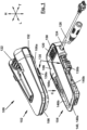
- a fastening device is generally denoted by reference numeral 100.
- the fastening device 100 is adapted and intended to releasably fasten a functional unit 102 to a receiving unit 104.
- Both, the functional unit 102 and the receiving unit 104, are three-dimensional bodies extending in a longitudinal direction L, a transverse direction T and a height direction H.
- the functional unit 102 In order to fasten the functional unit 102 to the receiving unit 104, the functional unit 102 is approached to the receiving unit 104 in a connection direction C extending substantially parallel to the height direction H.
- the functional unit 102 has a functional unit abutment surface 106 and the receiving unit 104 has a receiving unit abutment surface 108.
- the functional unit abutment surface 106 and the receiving unit abutment surface 108 are abutting against each other and are aligned to each other.
- Figure 1 shows the functional unit 102 and the receiving unit 104 separated from each other, in other words in a detached state
- Figure 2 shows a cross-sectional view of the functional unit 102 and the receiving unit 104 in a connected state.
- the fastening device 100 comprises at least one pair of magnets 110.
- Said at least one pair of magnets 110 comprises at least one functional unit magnet 112 allocated to the functional unit 102 and at least one receiving unit magnet 114 allocated to the receiving unit 104.
- the positions of the at least one receiving unit magnet 114 and the at least one functional unit magnet 112 are substantially aligned to each other in a plane extending substantially parallel to the longitudinal direction L and the transverse direction T.
- the at least one functional unit magnet 112 is located in a functional unit recess 116 provided in the functional unit 102 close to the functional unit abutment surface 106, and the at least one receiving unit magnet 114 is located in a receiving unit recess 118 provided in the receiving unit 104 close to the receiving unit abutment surface 108.
- the functional unit 102 comprises two pairs 110 of magnets 112, 114, namely a first pair 110' located in longitudinal direction L at the front end of a housing 102a of the functional unit 102, i.e. in front of a functional device 102b of the functional unit 102, and a second pair 110" located in longitudinal direction L at the rear end of the housing 102a, i.e. behind the functional device 102b.
- the magnets' effect on the electrical components of the functional device 102b, in particular the capacitors thereof, and, in case of the functional device 102b including a communication device, the RF antenna(s) thereof may be reduced.
- the magnets 112, 114 of the at least one pair of magnets 110 both are permanent magnets, i.e. active magnets, it is to be noted that it is also conceivable that one of the magnets may be a passive magnet, i.e. a magnet having a magnetic field only due to being magnetized by an active magnet.
- the functional unit abutment surface 106 comprises at least one inclined functional unit abutment surface portion 106a
- the receiving unit abutment surface 108 comprises at least one inclined receiving unit abutment surface portion 108a.
- Said at least one inclined functional unit abutment surface portion 106a and said at least one inclined receiving unit abutment surface portion 108a extend at substantially the same inclination angle.
- the at least one inclined functional unit abutment surface portion 106a and the at least one inclined receiving unit abutment surface portion 108a abut against each other in the connected state.
- a plurality of inclined functional unit abutment surface portions 106a and a plurality of inclined receiving unit abutment surface portions 108a may be provided around the circumference of the functional unit 102 and the receiving unit 104, respectively.
- the receiving unit 104 further comprises electrical contacts 120 which are adapted and intended for being electrically connected to electrical counter-contacts (not shown) of the functional unit 102. As is per se known, these contacts 120 and counter-contacts in their connected state are intended for supplying commands input via an operating element 122 or signals derived from such commands to signal lines 124 and/or 126 connected to the receiving unit 104 and leading to at least one remote device (not shown).
- the fastening device 100 comprises two mechanical locking units 130, one at each lateral side of the fastening device, and only one being shown in Figure 1 .
- Each mechanical locking unit 130 comprises a functional unit locking element 130a allocated to the functional unit 102 and a receiving unit locking element 130b allocated to the receiving unit 104.
- Figure 3 is an enlarged cross-sectional view of the fastening device 100 cut along a plane spanned in transverse direction T and height direction H and shows the design of the mechanical locking unit 130 in more detail.
- the mechanical locking unit 130 is designed as a snap-lock unit and comprises a catch element 132 and a trap element 134.
- the catch element 132 is provided with a catch sliding surface 132a and a catch end 132b.
- the trap element 134 is provided with a trap sliding surface 134a and a catch end 134b.
- the functional unit 102 comprises a functional portion 102b extending laterally beyond the catch element 132.
- the catch element 132 further comprises a resilient web 132c connecting the catch end 132b to the allocated unit, here the receiving unit 104.
- a backing wall element 138 is provided at a predetermined distance d from the connection of the resilient web 132c to the allocated unit, here the receiving unit 104.
- the functional unit 102 is approached to the receiving unit 104 in the connection direction C.
- the at least one pair of magnets 110 exerts an attractive force supporting the approaching and resulting in a self-centering effect of the two units 102, 104.
- This self-centering effect is enhanced by the cooperation of the at least one inclined functional unit surface portion 106a and the at least one inclined receiving unit surface portion 108a.
- the trap sliding surface 134a and the catch sliding surface 132a of the at least one mechanical locking unit 130 slide along each other and the catch end 134b of the catch element 134 is deflected to a locking preparation position LPP indicated by a dashed line in Figure 3 .
- This is enabled by the resilient web 132c being elastically deflected towards the backing wall element 138.
- the catch sliding surface 132a and the trap sliding surface 134a slide along each other in connection direction C in a guided manner, until the trap end 132b passes the catch end 134b.
- the elastic deflection of the catch end 134b is reversed and the catch end 134b automatically returns to its undeflected position shown in Figure 3 .
- the catch element 134 and the trap element 132 engage with each other.
- the catch end 134b engages into the trap recess 132d.
- the functional unit 102 is locked to the receiving unit 104. This process is supported by the attractive force of the at least one pair of magnets 110.
- the functional unit 102 and the receiving unit 104 are attached to each other in connection direction C by the attractive force exerted by the at least one pair of magnets 110 and the snap-lock engagement of the at least one mechanical locking unit 130.
- the fastening device 100 further comprises a securing element 140 securing the functional unit 102 from being detached from the receiving unit 104 in a detaching direction D extending substantially parallel to the longitudinal direction L.
- Figures 1 and 2 show the securing element 140 in its securing position.
- the securing element 140 is provided at and integrally formed with the receiving unit 104 (see Figure 1 ). Formed in a U-shape, the securing element 140 extends partially around the receiving unit 104.
- the securing element 140 includes a connecting web 140a connects two side webs 140b.
- the connecting web 140a is extends substantially in transverse direction T, while the two side webs 140b extend substantially in longitudinal direction L, and are attached by their free ends to the receiving unit 104.
- the connecting web 140a thereof blocks any movement of the functional unit 102 in the detaching direction D (see reference numeral BL).
- the securing element 140 may be transferred from the securing position SP to a releasing position RP indicated by a dashed line in Figure 4 , in particular by deflecting its connecting web 140a downwards in the height direction H.
- the securing position SP is defined by the cooperation of a movement limiting abutment surface 142a provided at the securing element 140 and a cooperating movement limiting abutment surface 142b provided at the receiving unit 104.
- the movement limiting abutment surface 142a and the cooperating movement limiting abutment surface 142b together form first movement limiting means 142.
- the first movement limiting means 142 prevent the securing element 140 from moving beyond the securing position SP.
- the releasing position RP is defined by the cooperation of a further movement limiting abutment surface 144a provided at the securing element 140 and a further cooperating movement limiting abutment surface 144b provided at the receiving unit 104.
- the further movement limiting abutment surface 144a and the further cooperating movement limiting abutment surface 144b together form second movement limiting means 144.
- the second movement limiting means 144 prevent the securing element 140 from moving beyond the releasing position RP.
- a stopper surface 150 (see Figure 1 ) provided at the receiving unit 104 and a stopper counter-surface 152 provided at the functional unit 102 prevent a relative movement in a direction opposite to the detaching direction D.
- the stopper surface 150 and the stopper counter surface 152 abut against each other in the connected state of the functional unit 102 and the receiving unit 104 (see Figure 2 ).
Landscapes
- Engineering & Computer Science (AREA)
- General Engineering & Computer Science (AREA)
- Mechanical Engineering (AREA)
- Helmets And Other Head Coverings (AREA)
- Details Of Connecting Devices For Male And Female Coupling (AREA)
- Casings For Electric Apparatus (AREA)
- Clamps And Clips (AREA)
- Connection Of Plates (AREA)
Claims (16)
- Kombination aus einer Funktionseinheit (102), einer Aufnahmeeinheit (104) und einer Befestigungsvorrichtung (100) zur lösbaren Befestigung der Funktionseinheit (102) in einer Verbindungsrichtung (C) an der Aufnahmeeinheit (104),wobei die Funktionseinheit (102) und die Aufnahmeeinheit (104) jeweils eine Längsrichtung (L), eine Querrichtung (T) und eine Höhenrichtung (H) aufweisen,wobei die Funktionseinheit (102) ferner eine Funktionseinheits-Anlagefläche (106) aufweist und die Aufnahmeeinheit (104) ferner eine Aufnahmeeinheits-Anlagefläche (108) aufweist, wobei die Funktionseinheits-Anlagefläche (106) und die Aufnahmeeinheits-Anlagefläche (108) dazu ausgelegt sind, im verbundenen Zustand aneinander anzuliegen,wobei die Befestigungsvorrichtung (100) ferner mindestens ein Paar von Magneten (110) umfasst, wobei mindestens ein Funktionseinheits-Magnet (112) an oder nahe der Funktionseinheits-Anlagefläche (106) angeordnet ist und mindestens ein Aufnahmeeinheits-Magnet (114) an oder nahe der Aufnahmeeinheits-Anlagefläche (108) angeordnet ist, wobei die Magnete (112, 114) des mindestens einen Paares von Magneten (110) eine Anziehungskraft aufeinander ausüben,wobei die Befestigungsvorrichtung (100) ferner mindestens eine mechanische Verriegelungseinheit (130) umfasst, die ein der Funktionseinheit (102) zugeordnetes Funktionseinheits-Verriegelungselement (130a) der Funktionseinheit und ein der Aufnahmeeinheit (104) zugeordnetes Aufnahmeeinheits-Verriegelungselement (130b) der Aufnahmeeinheit umfasst, wobei die Verriegelungselemente (130a, 130b) geeignet und bestimmt sind, miteinander zusammenzuwirken,dadurch gekennzeichnet, dassdie Funktionseinheit (102) eine Kommunikationsvorrichtung (154) umfasst,die mindestens eine mechanische Verriegelungseinheit (130) als Schnappverriegelungseinheit ausgebildet ist, die mindestens ein Rastelement (132) und mindestens ein Fangelement (134) umfasst, die geeignet und bestimmt sind, miteinander zusammenzuwirken, unddie Befestigungsvorrichtung (100) ferner ein Sicherungselement (140) umfasst, wobei das Sicherungselement (140) zwischen einer Sicherungsstellung und einer Freigabestellung überführbar ist, wobei das Sicherungselement (140) geeignet ist, in seiner Sicherungsstellung eine Bewegung der Funktionseinheit (102) relativ zur Aufnahmeeinheit (104) in einer Löserichtung (142) zu verhindern, während es in seiner Freigabestellung eine solche Bewegung zulässt,wobei eine Auslenkrichtung eines Rastendes des mindestens einen Rastelementes (132) im Wesentlichen parallel zu einer ersten Richtung, nämlich der Querrichtung (T) oder der Längsrichtung (L), verläuft, wobei die Löserichtung im Wesentlichen parallel zu einer zweiten Richtung, nämlich der Längsrichtung (L) oder der Querrichtung (T), d.h. im Wesentlichen orthogonal zu beiden, der Auslenkrichtung und der Verbindungsrichtung (C), verläuft.
- Die Kombination nach Anspruch 1,
wobei mindestens einer der Funktionseinheits-Magnet (112) und der Aufnahmeeinheits-Magnet (114) ein aktiver Magnet ist, z.B. ein Permanentmagnet oder ein Elektromagnet. - Die Kombination nach Anspruch 1 oder 2,
wobei sich die Positionen des mindestens einen Funktionseinheits-Magneten (112) und des mindestens einen Aufnahmeeinheits-Magneten (114) im verbundenen Zustand in Verbindungsrichtung (C) gesehen zumindest teilweise überlappen, vorzugsweise im Wesentlichen zueinander ausgerichtet sind. - Kombination nach einem der vorhergehenden Ansprüche,
wobei die Funktionseinheit (102) ein Gehäuse (102a) und eine in dem Gehäuse (102a) aufgenommene Funktionseinrichtung (102b) umfasst, und wobei die Befestigungsvorrichtung (100) mindestens zwei Magnetpaare (110) aufweist, die beide außerhalb der Funktionseinrichtung (102b), vorzugsweise in Längs- oder Querrichtung gesehen, an gegenüberliegenden Seiten der Funktionseinrichtung (102b) angeordnet sind. - Kombination nach einem der vorhergehenden Ansprüche,
wobei die Funktionseinheits-Anlagefläche (106) mindestens einen schrägen Funktionseinheits-Anlageflächenabschnitt (106a) und die Aufnahmeeinheits-Anlagefläche (108) mindestens einen schrägen Aufnahmeeinheits-Anlageflächenabschnitt (108a) aufweist, die im verbundenen Zustand der Funktionseinheit (102) und der Aufnahmeeinheit (104) zumindest teilweise zu dem mindestens einen schrägen Funktionseinheits-Anlageflächenabschnitt (106a) ausgerichtet sind. - Kombination nach einem der vorhergehenden Ansprüche,
wobei an jeder lateralen Seite der Funktionseinheit (102) und der Aufnahmeeinheit (104) mindestens eine mechanische Verriegelungseinheit (130) vorgesehen ist. - Kombination nach einem der vorangehenden Ansprüche,
wobei das mindestens eine Fangelement (134) mit einer Fanggleitfläche (134a) und das mindestens eine Rastelement (132) mit einer Rastgleitfläche (132a) versehen ist, wobei die Fanggleitfläche (134a) und die Rastgleitfläche (132a) beim Entlanggleiten aneinander ein Rastende (132b) des Rastelements (132) elastisch in eine Verriegelungsvorbereitungsposition auslenken. - Kombination nach einem der vorhergehenden Ansprüche,
wobei das mindestens eine Rastelement (132) einen federnden Steg (132c) aufweist, der das Rastende (132b) mit der jeweils zugeordneten Einheit, d.h. der Aufnahmeeinheit (104) oder der Funktionseinheit (102), vorzugsweise der Aufnahmeeinheit (104), verbindet. - Kombination nach Anspruch 8,
wobei in einem vorbestimmten Abstand (d) von der Anbindung des elastischen Stegs (132c) an die jeweils zugeordnete Einheit, d.h. die Aufnahmeeinheit (104) oder die Funktionseinheit (102), vorzugsweise die Aufnahmeeinheit (104), ein im Wesentlichen parallel zum elastischen Steg (132c) verlaufendes Rückwandelement (138) vorgesehen ist. - Kombination nach einem der vorhergehenden Ansprüche,
wobei sich die Funktionseinheit (102) nach außen über das mindestens eine Rastelement (132) hinaus erstreckt. - Kombination nach einem der vorhergehenden Ansprüche.
wobei das Sicherungselement (140) an der ihm zugeordneten Einheit, nämlich der Aufnahmeeinheit (104) oder der Funktionseinheit (102), vorzugsweise der Aufnahmeeinheit (104), vorgesehen, vorzugsweise mit dieser integral ausgebildet, ist. - Kombination nach einem der vorhergehenden Ansprüche,
wobei das Sicherungselement (140) U-förmig ausgebildet ist. - Kombination nach einem der vorhergehenden Ansprüche, wobei die Befestigungsvorrichtung (100) ferner eine erste Bewegungsbegrenzungseinrichtung (142) umfasst, die geeignet ist, zu verhindern, dass das Sicherungselement (140) über die Sicherungsposition hinaus bewegt wird, und/oder eine zweite Bewegungsbegrenzungseinrichtung (148), die geeignet ist, zu verhindern, dass das Sicherungselement (140) über die Freigabeposition hinaus bewegt wird.
- Kombination nach einem der vorhergehenden Ansprüche,
wobei die Befestigungsvorrichtung (100) ferner eine an der Aufnahmeeinheit (104) vorgesehene Anschlagfläche (150) und eine an der Funktionseinheit (102) vorgesehene Anschlag-Gegenfläche (152) umfasst, die geeignet und dazu bestimmt ist, mit der Anschlagfläche (150) zusammenzuwirken, um eine Bewegung der Funktionseinheit (102) relativ zu der Aufnahmeeinheit (104) in einer der Löserichtung (142) entgegengesetzten Richtung zu begrenzen. - Kombination nach einem der vorhergehenden Ansprüche,
wobei die Kommunikationsvorrichtung (154) Bluetooth®-Technologie verwendet. - Kombination nach einem der vorangehenden Ansprüche,
wobei die Aufnahmeeinheit (104) Teil einer Kopfschutzausrüstung ist oder als separate Einheit ausgebildet ist, die an der Kopfschutzausrüstung betriebsmäßig befestigt werden kann.
Applications Claiming Priority (2)
| Application Number | Priority Date | Filing Date | Title |
|---|---|---|---|
| PCT/IB2020/060404 WO2022096918A1 (en) | 2020-11-05 | 2020-11-05 | Magnetic fastening device |
| PCT/IB2021/060221 WO2022097063A1 (en) | 2020-11-05 | 2021-11-04 | Fastening device, head-protective gear with such a fastening device |
Publications (3)
| Publication Number | Publication Date |
|---|---|
| EP4240194A1 EP4240194A1 (de) | 2023-09-13 |
| EP4240194B1 true EP4240194B1 (de) | 2024-10-09 |
| EP4240194C0 EP4240194C0 (de) | 2024-10-09 |
Family
ID=73452241
Family Applications (3)
| Application Number | Title | Priority Date | Filing Date |
|---|---|---|---|
| EP20807886.5A Active EP4013256B1 (de) | 2020-11-05 | 2020-11-05 | Magnetische befestigungsvorrichtung |
| EP23157694.3A Pending EP4201242A1 (de) | 2020-11-05 | 2020-11-05 | Magnetische befestigungsvorrichtung |
| EP21802827.2A Active EP4240194B1 (de) | 2020-11-05 | 2021-11-04 | Befestigungsvorrichtung, kopfschutzgetriebe mit einer solchen befestigungsvorrichtung |
Family Applications Before (2)
| Application Number | Title | Priority Date | Filing Date |
|---|---|---|---|
| EP20807886.5A Active EP4013256B1 (de) | 2020-11-05 | 2020-11-05 | Magnetische befestigungsvorrichtung |
| EP23157694.3A Pending EP4201242A1 (de) | 2020-11-05 | 2020-11-05 | Magnetische befestigungsvorrichtung |
Country Status (6)
| Country | Link |
|---|---|
| US (6) | US12439993B2 (de) |
| EP (3) | EP4013256B1 (de) |
| JP (2) | JP7736788B2 (de) |
| KR (2) | KR102832424B1 (de) |
| CN (2) | CN119073692B (de) |
| WO (2) | WO2022096918A1 (de) |
Families Citing this family (4)
| Publication number | Priority date | Publication date | Assignee | Title |
|---|---|---|---|---|
| US12287175B2 (en) * | 2020-08-21 | 2025-04-29 | Magne-Tech, Llc | Accessory mounts |
| EP4013256B1 (de) | 2020-11-05 | 2023-02-22 | Cardo Systems, Ltd. | Magnetische befestigungsvorrichtung |
| DE102022132430A1 (de) | 2022-12-07 | 2024-06-13 | ABUS August Bremicker Söhne Kommanditgesellschaft | Modulares Helmsystem |
| DE102023123618A1 (de) * | 2023-09-01 | 2025-03-06 | Busch PROtective Germany GmbH & Co. KG | Befestigungssystem und Verfahren zum Arretieren und Ablösen eines ersten Verschlusselements an bzw. von einem zweiten Verschlusselement mittels eines Befestigungssystems |
Family Cites Families (42)
| Publication number | Priority date | Publication date | Assignee | Title |
|---|---|---|---|---|
| US4521831A (en) | 1984-01-18 | 1985-06-04 | Thayer John R | Protective helmet with dual adjustment illumination means |
| ZA946001B (en) | 1993-08-11 | 1996-02-12 | Designodev Ltd | Flashlight adaptor |
| US5914816A (en) | 1997-11-04 | 1999-06-22 | Norotos, Inc. | Helmet mount for night vision goggle |
| GB2397372A (en) | 2003-01-15 | 2004-07-21 | Paul David Sherring | Electroluminescent position indicators for helmets |
| US6751810B1 (en) | 2003-03-13 | 2004-06-22 | Norotos, Inc. | Shroud plate |
| US7246384B2 (en) * | 2005-01-07 | 2007-07-24 | William George Bentz | Headgear and chin strap with magnetic fastener |
| CN102006794B (zh) | 2008-04-03 | 2012-11-21 | 3M创新有限公司 | 用于头盔的枢轴组件 |
| WO2010123797A1 (en) * | 2009-04-21 | 2010-10-28 | Berry Bret M | Apparatus for preventing head or neck injury using magnetic assistance |
| US8371707B2 (en) | 2009-06-03 | 2013-02-12 | Robert Timothy Uzar | Portable light source |
| US8739313B2 (en) | 2009-11-20 | 2014-06-03 | Wilcox Industries Corp. | Helmet mounting systems |
| US20120002046A1 (en) | 2010-06-30 | 2012-01-05 | Raytheon Company | Flip-Up Hands-Free Display Mount |
| US8600094B2 (en) | 2011-01-20 | 2013-12-03 | Cardo Systems, Inc. | Mounting panel with elongated tongue |
| US10028543B2 (en) | 2011-01-31 | 2018-07-24 | Darryl William Munns | Safety light helmet |
| US20160174647A1 (en) | 2011-05-04 | 2016-06-23 | Frances H. Benton | Self-Closing Helmet Strap |
| TWM417024U (en) | 2011-06-20 | 2011-12-01 | Tai Sol Electronics Co Ltd | Warning light for use on helmet |
| FR2978904B1 (fr) | 2011-08-08 | 2014-07-25 | Remi Finiel | Ensemble casque et masque de protection oculaire |
| US8908389B2 (en) | 2011-10-07 | 2014-12-09 | Wilcox Industries Corp. | Power distribution system and helmet and method employing the same |
| US9622529B2 (en) | 2012-07-18 | 2017-04-18 | Wilcox Industries Corp. | Helmet edge trim wiring harness |
| US10143270B2 (en) * | 2012-12-14 | 2018-12-04 | Fidlock Gmbh | Closure device for releasably connecting two parts |
| US20140317890A1 (en) | 2013-04-24 | 2014-10-30 | Pacific Cycle, Llc | Helmet buckle with magnetic alignment |
| US10021931B2 (en) | 2014-04-02 | 2018-07-17 | Sopro Mounts Inc. | Helmet-chin mount for accessories, including cameras |
| US20150286117A1 (en) | 2014-04-07 | 2015-10-08 | Ermi, Inc. | Portable electronic device mounting system |
| WO2015179802A1 (en) | 2014-05-23 | 2015-11-26 | NUVIZ, Inc. | Helmet mounted display |
| US9756930B2 (en) | 2015-04-28 | 2017-09-12 | Axon Enterprise, Inc. | Methods and apparatus for a low-profile coupler |
| WO2017003930A1 (en) | 2015-07-02 | 2017-01-05 | Frances Benton | Self-closing helmet strap |
| US9829772B2 (en) | 2015-09-01 | 2017-11-28 | Gopro, Inc. | Removable camera mount for a helmet |
| US9507245B1 (en) | 2015-09-15 | 2016-11-29 | Gopro, Inc. | Detachable camera mount |
| EP3251984B1 (de) * | 2016-05-31 | 2018-10-31 | Multipond Wägetechnik GmbH | Verbindungseinrichtung |
| US10492559B1 (en) | 2016-09-12 | 2019-12-03 | Bell Sports, Inc. | Helmet with removable chin bar |
| CN106953657B (zh) * | 2017-03-31 | 2023-03-31 | 汉得利(常州)电子股份有限公司 | 一种骨传导头盔通话装置 |
| TWI626899B (zh) | 2017-06-14 | 2018-06-21 | Zhang le yan | 頭盔 |
| DE102017212149A1 (de) | 2017-07-14 | 2019-01-17 | Fidlock Gmbh | Verschlussvorrichtung mit elektrischem Kontakt |
| IT201800007541A1 (it) | 2018-07-26 | 2020-01-26 | Nolangroup Spa | Casco di protezione con meccanismo di sollevamento/abbassamento della visiera |
| US10912344B2 (en) | 2018-12-03 | 2021-02-09 | Msa Technology, Llc | Helmet with accessory attachment rail |
| US11129431B2 (en) | 2019-05-07 | 2021-09-28 | Bell Sports, Inc. | Magnetic goggle attachment |
| US11213089B2 (en) | 2019-06-04 | 2022-01-04 | Msa Technology, Llc | Protective helmet with face protection shield and linkage mechanism |
| KR102209939B1 (ko) * | 2019-06-18 | 2021-02-01 | 주식회사 우진프라스틱 | 버클 |
| EP4069065A4 (de) | 2019-12-05 | 2023-11-15 | InteraXon Inc. | Tragbare vorrichtung |
| US12287175B2 (en) | 2020-08-21 | 2025-04-29 | Magne-Tech, Llc | Accessory mounts |
| EP4013256B1 (de) | 2020-11-05 | 2023-02-22 | Cardo Systems, Ltd. | Magnetische befestigungsvorrichtung |
| CN114027582B (zh) | 2021-04-18 | 2023-09-15 | 联扬塑胶(深圳)有限公司 | 磁性扣具 |
| KR102740952B1 (ko) * | 2022-09-21 | 2024-12-10 | 아날로그플러스 주식회사 | 헬멧용 자석 버클 |
-
2020
- 2020-11-05 EP EP20807886.5A patent/EP4013256B1/de active Active
- 2020-11-05 EP EP23157694.3A patent/EP4201242A1/de active Pending
- 2020-11-05 WO PCT/IB2020/060404 patent/WO2022096918A1/en not_active Ceased
-
2021
- 2021-11-04 CN CN202411125616.1A patent/CN119073692B/zh active Active
- 2021-11-04 CN CN202180089136.2A patent/CN116709943A/zh active Pending
- 2021-11-04 KR KR1020237018766A patent/KR102832424B1/ko active Active
- 2021-11-04 JP JP2023527094A patent/JP7736788B2/ja active Active
- 2021-11-04 US US18/035,605 patent/US12439993B2/en active Active
- 2021-11-04 EP EP21802827.2A patent/EP4240194B1/de active Active
- 2021-11-04 WO PCT/IB2021/060221 patent/WO2022097063A1/en not_active Ceased
- 2021-11-04 KR KR1020257021993A patent/KR20250109785A/ko active Pending
-
2022
- 2022-02-18 US US17/675,425 patent/US11484086B2/en active Active
- 2022-09-28 US US17/955,236 patent/US12102163B2/en active Active
-
2023
- 2023-10-13 US US18/486,829 patent/US12048344B2/en active Active
-
2024
- 2024-09-20 US US18/891,226 patent/US20250009064A1/en active Pending
-
2025
- 2025-02-12 US US19/051,778 patent/US12349758B2/en active Active
- 2025-07-03 JP JP2025113159A patent/JP2025158977A/ja active Pending
Also Published As
| Publication number | Publication date |
|---|---|
| WO2022096918A1 (en) | 2022-05-12 |
| WO2022097063A1 (en) | 2022-05-12 |
| US12439993B2 (en) | 2025-10-14 |
| US12048344B2 (en) | 2024-07-30 |
| JP7736788B2 (ja) | 2025-09-09 |
| EP4201242A1 (de) | 2023-06-28 |
| US11484086B2 (en) | 2022-11-01 |
| JP2023548195A (ja) | 2023-11-15 |
| EP4013256A1 (de) | 2022-06-22 |
| US20220218064A1 (en) | 2022-07-14 |
| US20250009064A1 (en) | 2025-01-09 |
| CN119073692B (zh) | 2025-07-08 |
| JP2025158977A (ja) | 2025-10-17 |
| US20250176654A1 (en) | 2025-06-05 |
| KR20230098850A (ko) | 2023-07-04 |
| US20240032638A1 (en) | 2024-02-01 |
| EP4240194A1 (de) | 2023-09-13 |
| EP4240194C0 (de) | 2024-10-09 |
| KR102832424B1 (ko) | 2025-07-10 |
| US20230404200A1 (en) | 2023-12-21 |
| US20230021199A1 (en) | 2023-01-19 |
| US12349758B2 (en) | 2025-07-08 |
| CN119073692A (zh) | 2024-12-06 |
| CN116709943A (zh) | 2023-09-05 |
| EP4013256B1 (de) | 2023-02-22 |
| US12102163B2 (en) | 2024-10-01 |
| KR20250109785A (ko) | 2025-07-17 |
Similar Documents
| Publication | Publication Date | Title |
|---|---|---|
| EP4240194B1 (de) | Befestigungsvorrichtung, kopfschutzgetriebe mit einer solchen befestigungsvorrichtung | |
| US7600268B2 (en) | Helmet retention system with improved stability | |
| US20100325784A1 (en) | Helmet Clip | |
| AU2011278393B2 (en) | Protective helmet, in particular for forestry workers | |
| AU2019271373B2 (en) | Protection attachment for a helmet | |
| US20150286117A1 (en) | Portable electronic device mounting system | |
| US20070169251A1 (en) | Adjustment mechanism for a helmet | |
| CN116649668A (zh) | 护颏罩附接系统和方法 | |
| HK40100703A (en) | Fastening device, head-protective gear with such a fastening device | |
| HK40100703B (en) | Fastening device, head-protective gear with such a fastening device | |
| WO2018055087A1 (en) | Face guard, face guard receiving system and head protection system | |
| EP4052602B1 (de) | Helm mit mikrofontragearm | |
| WO2024100522A1 (en) | Connection device | |
| US20230232930A1 (en) | Customizable snap cover for open face helmets | |
| US20240168315A1 (en) | Eyewear lens attachment system | |
| KR102674529B1 (ko) | 부착패드가 구성된 스마트폰 케이스 | |
| WO2025245536A1 (en) | Magnetic quick-release closure system |
Legal Events
| Date | Code | Title | Description |
|---|---|---|---|
| STAA | Information on the status of an ep patent application or granted ep patent |
Free format text: STATUS: UNKNOWN |
|
| STAA | Information on the status of an ep patent application or granted ep patent |
Free format text: STATUS: THE INTERNATIONAL PUBLICATION HAS BEEN MADE |
|
| PUAI | Public reference made under article 153(3) epc to a published international application that has entered the european phase |
Free format text: ORIGINAL CODE: 0009012 |
|
| STAA | Information on the status of an ep patent application or granted ep patent |
Free format text: STATUS: REQUEST FOR EXAMINATION WAS MADE |
|
| 17P | Request for examination filed |
Effective date: 20230525 |
|
| AK | Designated contracting states |
Kind code of ref document: A1 Designated state(s): AL AT BE BG CH CY CZ DE DK EE ES FI FR GB GR HR HU IE IS IT LI LT LU LV MC MK MT NL NO PL PT RO RS SE SI SK SM TR |
|
| DAV | Request for validation of the european patent (deleted) | ||
| DAX | Request for extension of the european patent (deleted) | ||
| STAA | Information on the status of an ep patent application or granted ep patent |
Free format text: STATUS: EXAMINATION IS IN PROGRESS |
|
| REG | Reference to a national code |
Ref country code: HK Ref legal event code: DE Ref document number: 40100703 Country of ref document: HK |
|
| 17Q | First examination report despatched |
Effective date: 20240412 |
|
| GRAP | Despatch of communication of intention to grant a patent |
Free format text: ORIGINAL CODE: EPIDOSNIGR1 |
|
| STAA | Information on the status of an ep patent application or granted ep patent |
Free format text: STATUS: GRANT OF PATENT IS INTENDED |
|
| GRAS | Grant fee paid |
Free format text: ORIGINAL CODE: EPIDOSNIGR3 |
|
| GRAA | (expected) grant |
Free format text: ORIGINAL CODE: 0009210 |
|
| STAA | Information on the status of an ep patent application or granted ep patent |
Free format text: STATUS: THE PATENT HAS BEEN GRANTED |
|
| INTG | Intention to grant announced |
Effective date: 20240823 |
|
| AK | Designated contracting states |
Kind code of ref document: B1 Designated state(s): AL AT BE BG CH CY CZ DE DK EE ES FI FR GB GR HR HU IE IS IT LI LT LU LV MC MK MT NL NO PL PT RO RS SE SI SK SM TR |
|
| REG | Reference to a national code |
Ref country code: CH Ref legal event code: EP |
|
| REG | Reference to a national code |
Ref country code: DE Ref legal event code: R096 Ref document number: 602021020073 Country of ref document: DE |
|
| REG | Reference to a national code |
Ref country code: IE Ref legal event code: FG4D |
|
| U01 | Request for unitary effect filed |
Effective date: 20241014 |
|
| U07 | Unitary effect registered |
Designated state(s): AT BE BG DE DK EE FI FR IT LT LU LV MT NL PT RO SE SI Effective date: 20241030 |
|
| U20 | Renewal fee for the european patent with unitary effect paid |
Year of fee payment: 4 Effective date: 20241028 |
|
| U30 | Action lodged before the upc [information provided by the upc] |
Free format text: ACTION-TYPE: INFRINGEMENT ACTION; CASE-NUMBER: ACT_64309/2024 Effective date: 20241206 |
|
| PG25 | Lapsed in a contracting state [announced via postgrant information from national office to epo] |
Ref country code: HR Free format text: LAPSE BECAUSE OF FAILURE TO SUBMIT A TRANSLATION OF THE DESCRIPTION OR TO PAY THE FEE WITHIN THE PRESCRIBED TIME-LIMIT Effective date: 20241009 Ref country code: IS Free format text: LAPSE BECAUSE OF FAILURE TO SUBMIT A TRANSLATION OF THE DESCRIPTION OR TO PAY THE FEE WITHIN THE PRESCRIBED TIME-LIMIT Effective date: 20250209 |
|
| PG25 | Lapsed in a contracting state [announced via postgrant information from national office to epo] |
Ref country code: ES Free format text: LAPSE BECAUSE OF FAILURE TO SUBMIT A TRANSLATION OF THE DESCRIPTION OR TO PAY THE FEE WITHIN THE PRESCRIBED TIME-LIMIT Effective date: 20241009 |
|
| PG25 | Lapsed in a contracting state [announced via postgrant information from national office to epo] |
Ref country code: NO Free format text: LAPSE BECAUSE OF FAILURE TO SUBMIT A TRANSLATION OF THE DESCRIPTION OR TO PAY THE FEE WITHIN THE PRESCRIBED TIME-LIMIT Effective date: 20250109 |
|
| PG25 | Lapsed in a contracting state [announced via postgrant information from national office to epo] |
Ref country code: GR Free format text: LAPSE BECAUSE OF FAILURE TO SUBMIT A TRANSLATION OF THE DESCRIPTION OR TO PAY THE FEE WITHIN THE PRESCRIBED TIME-LIMIT Effective date: 20250110 |
|
| PG25 | Lapsed in a contracting state [announced via postgrant information from national office to epo] |
Ref country code: PL Free format text: LAPSE BECAUSE OF FAILURE TO SUBMIT A TRANSLATION OF THE DESCRIPTION OR TO PAY THE FEE WITHIN THE PRESCRIBED TIME-LIMIT Effective date: 20241009 |
|
| PG25 | Lapsed in a contracting state [announced via postgrant information from national office to epo] |
Ref country code: RS Free format text: LAPSE BECAUSE OF FAILURE TO SUBMIT A TRANSLATION OF THE DESCRIPTION OR TO PAY THE FEE WITHIN THE PRESCRIBED TIME-LIMIT Effective date: 20250109 |
|
| REG | Reference to a national code |
Ref country code: CH Ref legal event code: PL |
|
| PG25 | Lapsed in a contracting state [announced via postgrant information from national office to epo] |
Ref country code: SM Free format text: LAPSE BECAUSE OF FAILURE TO SUBMIT A TRANSLATION OF THE DESCRIPTION OR TO PAY THE FEE WITHIN THE PRESCRIBED TIME-LIMIT Effective date: 20241009 |
|
| PG25 | Lapsed in a contracting state [announced via postgrant information from national office to epo] |
Ref country code: MC Free format text: LAPSE BECAUSE OF FAILURE TO SUBMIT A TRANSLATION OF THE DESCRIPTION OR TO PAY THE FEE WITHIN THE PRESCRIBED TIME-LIMIT Effective date: 20241009 |
|
| REG | Reference to a national code |
Ref country code: CH Ref legal event code: PL |
|
| PG25 | Lapsed in a contracting state [announced via postgrant information from national office to epo] |
Ref country code: CH Free format text: LAPSE BECAUSE OF NON-PAYMENT OF DUE FEES Effective date: 20241130 |
|
| PG25 | Lapsed in a contracting state [announced via postgrant information from national office to epo] |
Ref country code: SK Free format text: LAPSE BECAUSE OF FAILURE TO SUBMIT A TRANSLATION OF THE DESCRIPTION OR TO PAY THE FEE WITHIN THE PRESCRIBED TIME-LIMIT Effective date: 20241009 |
|
| PG25 | Lapsed in a contracting state [announced via postgrant information from national office to epo] |
Ref country code: CZ Free format text: LAPSE BECAUSE OF FAILURE TO SUBMIT A TRANSLATION OF THE DESCRIPTION OR TO PAY THE FEE WITHIN THE PRESCRIBED TIME-LIMIT Effective date: 20241009 |
|
| PLBE | No opposition filed within time limit |
Free format text: ORIGINAL CODE: 0009261 |
|
| STAA | Information on the status of an ep patent application or granted ep patent |
Free format text: STATUS: NO OPPOSITION FILED WITHIN TIME LIMIT |
|
| 26N | No opposition filed |
Effective date: 20250710 |
|
| PG25 | Lapsed in a contracting state [announced via postgrant information from national office to epo] |
Ref country code: IE Free format text: LAPSE BECAUSE OF NON-PAYMENT OF DUE FEES Effective date: 20241104 |
|
| U20 | Renewal fee for the european patent with unitary effect paid |
Year of fee payment: 5 Effective date: 20251029 |