EP4239998A1 - P-direction adjusting structure and dome camera - Google Patents
P-direction adjusting structure and dome camera Download PDFInfo
- Publication number
- EP4239998A1 EP4239998A1 EP21924491.0A EP21924491A EP4239998A1 EP 4239998 A1 EP4239998 A1 EP 4239998A1 EP 21924491 A EP21924491 A EP 21924491A EP 4239998 A1 EP4239998 A1 EP 4239998A1
- Authority
- EP
- European Patent Office
- Prior art keywords
- base
- pin
- upper cover
- wire hidden
- hidden case
- Prior art date
- Legal status (The legal status is an assumption and is not a legal conclusion. Google has not performed a legal analysis and makes no representation as to the accuracy of the status listed.)
- Granted
Links
Images





Classifications
-
- H—ELECTRICITY
- H04—ELECTRIC COMMUNICATION TECHNIQUE
- H04N—PICTORIAL COMMUNICATION, e.g. TELEVISION
- H04N23/00—Cameras or camera modules comprising electronic image sensors; Control thereof
- H04N23/50—Constructional details
-
- H—ELECTRICITY
- H04—ELECTRIC COMMUNICATION TECHNIQUE
- H04N—PICTORIAL COMMUNICATION, e.g. TELEVISION
- H04N23/00—Cameras or camera modules comprising electronic image sensors; Control thereof
- H04N23/50—Constructional details
- H04N23/52—Elements optimising image sensor operation, e.g. for electromagnetic interference [EMI] protection or temperature control by heat transfer or cooling elements
-
- H—ELECTRICITY
- H04—ELECTRIC COMMUNICATION TECHNIQUE
- H04N—PICTORIAL COMMUNICATION, e.g. TELEVISION
- H04N23/00—Cameras or camera modules comprising electronic image sensors; Control thereof
- H04N23/50—Constructional details
- H04N23/51—Housings
-
- G—PHYSICS
- G08—SIGNALLING
- G08B—SIGNALLING SYSTEMS, e.g. PERSONAL CALLING SYSTEMS; ORDER TELEGRAPHS; ALARM SYSTEMS
- G08B13/00—Burglar, theft or intruder alarms
- G08B13/18—Actuation by interference with heat, light, or radiation of shorter wavelength; Actuation by intruding sources of heat, light, or radiation of shorter wavelength
- G08B13/189—Actuation by interference with heat, light, or radiation of shorter wavelength; Actuation by intruding sources of heat, light, or radiation of shorter wavelength using passive radiation detection systems
- G08B13/194—Actuation by interference with heat, light, or radiation of shorter wavelength; Actuation by intruding sources of heat, light, or radiation of shorter wavelength using passive radiation detection systems using image scanning and comparing systems
- G08B13/196—Actuation by interference with heat, light, or radiation of shorter wavelength; Actuation by intruding sources of heat, light, or radiation of shorter wavelength using passive radiation detection systems using image scanning and comparing systems using television cameras
- G08B13/19617—Surveillance camera constructional details
- G08B13/1963—Arrangements allowing camera rotation to change view, e.g. pivoting camera, pan-tilt and zoom [PTZ]
-
- Y—GENERAL TAGGING OF NEW TECHNOLOGICAL DEVELOPMENTS; GENERAL TAGGING OF CROSS-SECTIONAL TECHNOLOGIES SPANNING OVER SEVERAL SECTIONS OF THE IPC; TECHNICAL SUBJECTS COVERED BY FORMER USPC CROSS-REFERENCE ART COLLECTIONS [XRACs] AND DIGESTS
- Y02—TECHNOLOGIES OR APPLICATIONS FOR MITIGATION OR ADAPTATION AGAINST CLIMATE CHANGE
- Y02E—REDUCTION OF GREENHOUSE GAS [GHG] EMISSIONS, RELATED TO ENERGY GENERATION, TRANSMISSION OR DISTRIBUTION
- Y02E40/00—Technologies for an efficient electrical power generation, transmission or distribution
- Y02E40/30—Reactive power compensation
Definitions
- the present application relates to the technical field of a camera, and in particular to a P-direction adjustable structure and a hemispherical camera.
- the purpose of the present application is to provide a P-direction adjustable structure and a hemispherical camera, which have a simple structure and are easy to operate.
- the present application provides a P-direction adjustable structure, which is applied to a hemispherical camera, including: an upper cover component, a pin, a cylindrical base, and a cylindrical wire hidden case;
- the present application provides a hemispherical camera, including the P-direction adjustable structure as stated above in the first aspect.
- the P-direction adjustable structure and the hemispherical camera of the embodiments of the present application have a simple structure and are easy to operate.
- the tightening operation in the P-direction is very simple, as long as the upper cover is normally shut and fastened, without a redundant operation.
- the angle adjustment of a hemisphere camera includes adjusting in three directions. After the camera is installed, the lens can be pointed at the area to be monitored through an angle adjustment mechanism in three directions.
- the P-direction refers to a rotation direction of which the rotation normal is perpendicular to the installation surface.
- the R-direction refers to a rotation direction of which the rotation normal coincides with the axis of the lens.
- the T-direction refers to a rotation direction where the rotation normal is perpendicular to the rotation normal of the P-direction and the rotation normal of the R-direction.
- the P-direction adjustable structure of the embodiments of the present application which is applied to a hemispherical camera, includes: an upper cover component 2, a pin 3, a cylindrical base 5, and a cylindrical wire hidden case 7.
- the base 5 and the wire hidden case 7 are connected to each other in a relatively rotatable manner.
- the upper cover component 2 is provided with a raised part to drive the pin 3 to move from a releasing position to a locking position. In the locking position, the pin 3 locks the rotation of the base 5 relative to the wire hidden case 7; in the releasing position, pin 3 releases the locking, allowing for a P-direction adjustment.
- the raised part on the upper cover component 2 drives the pin 3 to move from the releasing position to the locking position.
- the P-direction adjustable structure includes: a lens component 1, an upper cover component 2, a pin 3, an elastic component 34, a base 5, a damper 6, a wire hidden case 7, and a plate 8.
- the wire hidden case 7 and the base 5 are arranged to rotate relative to each other. That is, a rotating gap or a rotating play exists between the wire hidden case 7 and the base 5.
- the lens component 1 can rotate vertically and axially. That is, the lens component 1 can achieve the rotation along the T-direction and R-direction.
- the upper cover component 2 mainly includes an upper cover 21 and a hemispherical transparent hood 22.
- the upper cover 21 and the transparent hood 22 are fixedly connected and cannot rotate relative to each other.
- a first sealing ring 25 is arranged between the upper cover 21 and the transparent hood 22.
- the upper cover 21 and the transparent hood 22 are pressed against each other directly or through other pieces in order to compress the first sealing ring 25 and achieve sealing.
- the transparent hood 22 can be completely transparent, or can be a light insulating transparent hood 22 with a light insulating strip or a shading part (for example, only the middle portion is arranged to be transparent).
- the transparent hood 22 must rotate together and remain relatively stationary with the lens; otherwise, the lens will generate interference with the light insulating strip of the transparent hood 22.
- the upper cover component 2 is provided with a raised part for driving the pin 3.
- the raised part can adopt any appropriate shape and structure, which is not limited by the illustrated embodiments.
- the upper cover component 2 is installed on the base; the upper cover component 2 is provided with a raised part, which can drive the pin 3 to switch between the releasing position and the locking position; when the pin 3 is switched to the locking position, the rotational degree of freedom of the base 5 with respect to the wire hidden case 7 is locked; when the pin 3 is switched to the releasing position, the locking is released.
- the raised part is a driving protrusion 23 arranged on the upper cover 21.
- the driving protrusion 23 is integrally formed with the upper cover 21, or is fixed on the upper cover 21 or the upper cover component 2 in other ways.
- the raised part on upper cover component 2 drives the pin 3 to move from the releasing position to the locking position.
- the driving protrusion 23 is used to drive the pin 3 to move from the releasing position to the locking position. In the locking position, the pin 3 locks the rotation of the base 5 relative to the wire hidden case 7; and in the releasing position, the pin 3 releases the locking. That is, the driving protrusion 23 is used for locking and releasing the relative angle between the wire hidden case 7 and the base 5.
- an elastic body is arranged on the raised part or the driving protrusion 23, which is in contact with the pin 3 through the elastic body.
- the elastic body include a silicone plug 24 or a silicone cap arranged on the raised part or driving protrusion 23. As shown in Fig. 14 , the thin rod part of the silicone plug 24 is inserted into the central hole on the driving protrusion 23 in an interference fit manner, and the end of the silicone plug 24 is pressed against the flat surface of the driving protrusion 23.
- the pin 3 is arranged on the base 5 in a movable manner and has an anti detachment structure to prevent the pin 3 from falling off the base 5.
- the pin 3 passes through the first through hole 51 on the base 5.
- the first end of pin 3 (the tail 32 in the figures) faces (i.e. aligns with) the raised part or the driving protrusion 23, and the second end (head 31) faces (i.e. aligns with) a locking structure arranged on the wire hidden case 7.
- the pin 3 can move between the releasing position and the locking position.
- the first end of pin 3 disengages with the locking structure on the wire hidden case 7, thereby no longer preventing pin 3 from rotating relative to the wire hidden case 7, in other words, allowing pin 3 to rotate relative to the wire hidden case 7.
- the base 5 and wire hidden case 7 are allowed to rotate relative to the wire hidden case 7. It can be understood that when a P-direction adjustment is required, it is necessary to keep pin 3 in the releasing position.
- the second end of pin 3 is the head 31, and the first end is the tail 32.
- the head 31 is a radial expansion part, and its radial size is larger than the radial size of the rod part of the pin 3.
- the size and shape of the tail 32 are arranged to fit with the locking structure on the wire hidden case 7.
- the tail 32 is arranged in the shape of a wedge as shown in the figure to match the teeth 71 arranged in a circular array on the wire hidden case 7.
- the tail 32 can also be arranged in a conical shape to match the circular holes arranged in the circular array on the wire hidden case 7.
- the circular holes in the circular hole array are arranged to be separated from each other.
- the circular holes in the circular hole array are arranged to locally overlap, which can provide finer accuracy of the adjustment.
- the base 5 is arranged to rotate relative to the wire hidden case 7.
- the pin 3 is used to control whether the base 5 can rotate relative to the wire hidden case 7 for achieving the P-direction adjustment.
- the base 5 and the wire hidden case 7 can be assembled in any appropriate way, as long as the base 5 can rotate relative to the wire hidden case 7.
- the wire hidden case 7 is fixedly installed on mounting bases such as ceilings, columns, etc.
- the base 5 and the wire hidden case 7 are assembled in the following manner. Referring to Figs. 10 and 11 , the tightening screw 92 passes through the plate 8 and is pressed to the base 5, and the wire hidden case 7 is clamped between the plate 8 and the base 5. Thus, the assembly between the base 5 and the wire hidden case 7 is achieved.
- a gap exists between the wire hidden case 7 and the base 5 in an up-down direction, and a hole-shaft fit is formed at a middle portion. It can be the wire hidden case 7 with a matching hole and the base 5 with a matching shaft, or the wire hidden case 7 with a matching shaft and the base 5 with a matching hole.
- the relative rotation of the wire hidden case 7 and the base 5 is achieved or constrained by the hole-shaft fit.
- a damper 6 is arranged in the gap between the wire hidden case 7 and the base 5, which can generate a sense of damping during rotation.
- the damper 6 can be made of any suitable material, structure, or shape.
- two separate dampers 6 are provided, one being fixed relative to the wire hidden case 7 and the other being fixed relative to the base 5.
- only one damper 6 is provided, and the damper 6 is only provided between the wire hidden case 7 and the base 5, without being fixed relative to any one of the wire hidden case 7 and the base 5.
- the base 5 is provided with pins 3 that can move axially.
- the base 5 is provided with a first through hole 51.
- the pin 3 is inserted into the first through hole 51. It can be understood that the pin 3 is arranged in a gap fit manner within the first through hole 51.
- the pin 3 is restricted by an anti drop structure in the base 5 and cannot fall out.
- the anti drop structure is the snap spring 33.
- the snap spring 33 is clamped in the circular groove at the tail 32 of the pin 3, thereby preventing the pin 3 from falling off the base 5.
- the outer diameter of the snap spring 33 is greater than the diameter of the rod part of the pin 3. That is, outer diameters of the head 31 and the snap spring 33 are greater than a diameter of the first through hole 51.
- the anti drop structure can also use any other suitable structure such as an anti drop screw, a split pin that cross the pin 3, etc.
- an elastic component 34 is provided.
- the elastic component 34 is a compression spring.
- the elastic component 34 is arranged between the head 31 of the pin 3 and the base 5, that is, the two ends of the elastic component 34 abut against the head 31 and the base 5, respectively.
- the elastic component 34 raises the pin 3, so that the pin 3 is in the releasing position.
- the value of the single-side gap is 0.1mm-0.3mm.
- the single-side gap is set to be 0.2mm.
- the locking structure on the wire hidden case 7 is specifically teeth 71 arranged in a circular array.
- the tail 32 is arranged in the shape of a wedge as shown in the figure to match the teeth on the wire hidden case 7. The locking is achieved by inserting and fitting the tail 32 between the adjacent teeth 71. This prevents the base 5 from rotating relative to the wire hidden case 7.
- the teeth 71 are located at the radial edge position of the wire hidden case 7.
- the advantage of this is that the force arm can be increased during the limit, reducing the force applied by the same torque on the teeth 71 and improving reliability.
- the base 5 is directly exposed as part of the appearance of the camera.
- the base 5 can be directly rotated for achieving the P-direction adjustment.
- the lens component 1 is directly installed on the base 5. Therefore, the base 5 is used as a heat dissipation component and is directly exposed, greatly improving the heat dissipation efficiency compared to the technical solution where the heat dissipation component is installed inside the housing.
- the lens component 1 and the base 5 are fixed by a screw. After being fixed, the lens component 1 and the base 5 are relatively stationary and can rotate together relative to the wire hidden case 7. Due to the relative stationariness of the base 5 and the upper cover component 2, the lens component 1 is also relatively stationary relative to the transparent hood 22. In other words, the lens component 1 is integrated with the transparent hood 22 in the P-direction rotation.
- the upper cover 21 and the base 5 are fixed with a screw. After being fixed, the lens component 1, base 5, and the upper cover 21 are relatively stationary.
- the tightening and the loosening in the P-direction is mainly completed by three components: the wire hidden case 7, the base 5, and the upper cover component 2.
- the pin 3 on the base 5 is located directly below or above the teeth 71 of the wire hidden case 7.
- the pin 3 is raised; the pin 3 and the teeth 71 are not in contact, and the wire hidden case 7 and base 5 can rotate relative to each other, indicating a loosening state.
- the protrusion of the upper cover component 2 will inevitably be inserted into the hole of the base 5.
- the protrusion will raise the pin 3 upwards and the pin 3 is inserted into the teeth 71 of the wire hidden case 7, thereby limiting the relative rotation of the wire hidden case 7 and the base 5.
- the elastic body on the protrusion and the pin 3 are designed with a certain amount of interference to ensure close contact between the pin 3 and the teeth 71, avoiding any gap between the pin 3 and the teeth 71 that may cause shaking.
- the upper cover component 2 and the base 5 form one sealed chamber, and the lens component 1 is arranged in the sealed chamber.
- the PCB is also placed in the sealed chamber.
- the sealed chamber can use static sealing and waterproofing, and the sealing and waterproofing method is reliable.
- a second sealing ring 52 is arranged between the upper cover component 2 and the base 5, and the upper cover 21 and the base 5 are tightened with a screw to compress the silicone and achieve sealing.
- the upper cover component 2 and the base 5 are relatively fixed, forming a relatively static chamber that can be sealed statically, with reliable sealing and simple structure.
- the base 5 is directly exposed, and the PCB (not shown) and lens component 1 are directly installed on the base 5.
- the base 5 is used as a heat dissipation component and is directly exposed, which greatly improves the heat dissipation efficiency compared to the technical solution of arranging the heat dissipation component inside the housing.
- the P-direction adjustable structure includes a camera directional element, or a camera directional element is installed on the P-direction adjustable structure.
- a camera directional element that rotates together with the base is installed on the base 5, so that when performing the P-direction adjustment, the directions of the camera directional element and the lens can be adjusted simultaneously.
- the camera directional element include a microphone, a speaker, and/or a PIR (passive infrared sensor).
- the transparent hood 22 and the camera directional element can rotate together and remain relatively stationary with the lens.
- This solution is particularly suitable for the hemispherical camera with a light insulating transparent hood.
- the tightening operation in the P-direction is very simple, as long as the upper cover 21 is normally shut and fastened, without a redundant operation.
- a hemispherical camera including a lens component 1, an upper cover component 2, a cylindrical base 5, and a cylindrical wire hidden case 7.
- the upper cover component 2 includes a hemispherical transparent hood 22, which hoods the lens component 1.
- the base 5 supports the lens component 1 and the upper cover component 2, the cylindrical wire hidden case 7 supports the base 5, and the surface in the wire hidden case 7 which is in contact with the base 5 is provided with a through hole for receiving the wires of the lens component 1 through the base 5.
- the circumferential edge of the surface of the wire hidden case 7 is provided with teeth
- the wire hidden case 7 is defined such that: when the wire hidden case 7 is in non-fastened connection with the base 5, the base 5 can drive the lens component 1 and the wire hidden case 7 to rotate in the P-direction, so that the lens component 1 rotates to a preset angle; and when the wire hidden case 7 is in fastened connection with the base 5, the teeth of the wire hidden case 7 prevent the base 5 from rotating in the P-direction, so that the lens component 1 is defined at the preset angle.
- the upper cover component 2 includes a hemispherical transparent hood 22, which hoods the lens component 1.
- the transparent hood 22 can be completely transparent, or can be a light insulating transparent hood 22 with a light insulating strip or a shading part, for example, only the middle portion is arranged to be transparent.
- the transparent hood 22 must rotate together and remain relatively stationary with the lens; otherwise, the lens will generate interference with the light insulating strip of the transparent hood 22.
- the wire hidden case 7 and the base 5 are arranged to rotate relative to each other. That is, a rotating gap or a rotating play exists between the wire hidden case 7 and the base 5.
- a surface of the wire hidden case 7 in contact with the base 5 is provided with a through hole for receiving the wires of the lens component 1 through the base 5.
- the teeth 71 are located at the radial edge position of the wire hidden case 7. The advantage of this is that the force arm can be increased during the limit, reducing the force applied by the same torque on the teeth 71 and improving reliability.
- the base 5 can drive the lens component 1 and the wire hidden case 7 to rotate in the P-direction, so that the lens component 1 rotates to a preset angle.
- the teeth 71 of the wire hidden case 7 prevent the base 5 from rotating in the P-direction, so that the lens component 1 is defined at the preset angle.
- the base 5 and the wire hidden case 7 have the same first axis, and the rotating in the P-direction refers to a horizontal rotation around the first axis.
- the hemispherical camera also includes a pin 3.
- the pin 3 comes into contact with the teeth 71, the wire hidden case 7 is in fastened connection with the base 5.
- the pin 3 is loosened from the teeth 71, the wire hidden case 7 is in non-fastened connection with the base 5.
- the pin 3 is in contact with the teeth 71 to enable the base 5 and wire hidden case 7 to switch between a fastened connection state and a non-fastened connection state.
- the pin 3 In the initial/natural state, the pin 3 is in the releasing position.
- an elastic component 34 is provided.
- the elastic component 34 is a compression spring.
- the elastic component 34 is arranged between the head 31 of the pin 3 and the base 5, that is, two ends of the elastic component 34 abut against the head 31 and the base 5, respectively. In the natural state, the elastic component 34 raises the pin 3, so that the pin 3 is in the releasing position.
- the value of the single-side gap is 0.1mm-0.3mm.
- the single-side gap is set to be 0.2mm.
- the teeth 71 on the wire hidden case 7 are arranged in a circular array.
- the tail 32 is arranged in the shape of a wedge as shown in the figure to match the teeth on the wire hidden case 7. The locking is achieved by inserting and fitting the tail 32 between the adjacent teeth 71. This prevents the base 5 from rotating relative to the wire hidden case 7.
- the pin 3 runs parallel to the first axis through the base 5.
- the base 5 is provided with the pin 3 that can move axially.
- the base 5 is provided with a first through hole 51.
- the pin 3 is inserted into the first through hole 51. It can be understood that the pin 3 is arranged in a gap fit manner within the first through hole 51. The pin 3 is restricted by an anti drop structure in the base 5 and cannot fall out.
- the anti drop structure is the snap spring 33.
- the snap spring 33 is clamped in the circular groove at the tail 32 of the pin 3, thereby preventing the pin 3 from falling off the base 5.
- the outer diameter of the snap spring 33 is greater than the diameter of the rod part of the pin 3. That is, outer diameters of the head 31 and the snap spring 33 are greater than a diameter of the first through hole 51.
- the anti drop structure can also use any other suitable structure such as an anti drop screw, a split pin that cross the pin 3, etc.
- the base 5 and the wire hidden case 7 are assembled in the following manner. Referring to Figs. 10 and 11 , the tightening screw 92 passes through the plate 8 and is pressed to the base 5, and the wire hidden case 7 is clamped between the plate 8 and the base 5. Thus, the assembly between the base 5 and the wire hidden case 7 is achieved.
- a gap exists between the wire hidden case 7 and the base 5 in an up-down direction, and a hole-shaft fit is formed at a middle portion. It can be the wire hidden case 7 with a matching hole and the base 5 with a matching shaft, or the wire hidden case 7 with a matching shaft and the base 5 with a matching hole.
- the relative rotation of the wire hidden case 7 and the base 5 is achieved or constrained by the hole-shaft fit.
- the edge of upper cover component 2 includes a raised part, which extends towards the base 5.
- the pin 3 is subjected to pressure applied by the raised part to contact the pin 3 with the teeth 71.
- the upper cover component 2 is provided with a raised part for driving the pin 3.
- the raised part can adopt any appropriate shape and structure, which is not limited by the illustrated embodiments.
- the upper cover component 2 is installed on the base; the upper cover component 2 is provided with a raised part, which can drive the pin 3 to switch between the releasing position and the locking position; when the pin 3 is switched to the locking position, the rotational degree of freedom of the base 5 and the wire hidden case 7 is locked; when the pin 3 is switched to the releasing position, the locking is released.
- the raised part is a driving protrusion 23 arranged on the upper cover 21.
- the driving protrusion 23 is integrally formed with the upper cover component 21, or is fixed on the upper cover 21 or the upper cover component 2 in other ways.
- the raised part on upper cover component 2 drives the pin 3 to move from the releasing position to the locking position.
- the hemispherical camera also includes an elastic component, which sleeves the pin 3 to enable the pin 3 to move in a direction parallel to the first axis when subjected to or not subjected to pressure applied by the raised part.
- the base 5 is provided with pins 3 that can move axially.
- the base 5 is provided with a first through hole 51.
- the pin 3 is inserted into the first through hole 51. It can be understood that pin 3 is arranged in a gap fit manner within the first through hole 51.
- the elastic component sleeves the pin 3 to enable pin 3 to move in a direction parallel to the first axis when subjected to or not subjected to pressure applied by the raised part.
- the elastic component 34 is a compression spring.
- the elastic component 34 is arranged between the head 31 of the pin 3 and the base 5, that is, two ends of the elastic component 34 abut against the head 31 and the base 5, respectively. In the natural state, the elastic component 34 raises the pin 3, so that the pin 3 is located in the releasing position.
- the value of the single-side gap is 0.1mm-0.3mm.
- the single-side gap is set to be 0.2mm.
- the upper cover component 2 and the base 5 are tightened and fastened by a screw.
- the lens component 1 can rotate in a pitch direction.
- a camera directional element can be installed on the lens component 1. Specifically, a camera directional element that rotates together with the base is installed on base 5, so that during performing the P-direction adjustment, the direction of the camera directional element and the lens can be adjusted simultaneously.
- the camera directional element includes a microphone, a speaker, and/or a PIR passive infrared sensor.
- the transparent hood 22 and the camera directional element can rotate together and remain relatively stationary with the lens.
Landscapes
- Engineering & Computer Science (AREA)
- Multimedia (AREA)
- Signal Processing (AREA)
- Physics & Mathematics (AREA)
- Electromagnetism (AREA)
- Studio Devices (AREA)
Abstract
Description
- The present application claims the priority to a
Chinese Patent Application No. 202110168516.7, filed with State Intellectual Property Office of People's Republic of China on February 07, 2021 - The present application relates to the technical field of a camera, and in particular to a P-direction adjustable structure and a hemispherical camera.
- At present, for most hemispherical cameras, they have relatively complex structures, and the method for adjusting the lens component along the P-direction is relatively complex when setting up the camera.
- The purpose of the present application is to provide a P-direction adjustable structure and a hemispherical camera, which have a simple structure and are easy to operate.
- To achieve the above purpose, in the first aspect, the present application provides a P-direction adjustable structure, which is applied to a hemispherical camera, including: an upper cover component, a pin, a cylindrical base, and a cylindrical wire hidden case;
- wherein the base is rotatably connected to the wire hidden case;
- the upper cover component is installed on the base; the upper cover component is provided with a raised part, which can drive the pin to switch between a releasing position and a locking position;
- wherein, when the pin is switched to the locking position, a rotational degree of freedom of the base with respect to the wire hidden case is locked; when the pin is switched to the releasing position, locking is released.
- In the second aspect, the present application provides a hemispherical camera, including the P-direction adjustable structure as stated above in the first aspect.
- The P-direction adjustable structure and the hemispherical camera of the embodiments of the present application have a simple structure and are easy to operate. The tightening operation in the P-direction is very simple, as long as the upper cover is normally shut and fastened, without a redundant operation.
- In order to describe the technical solutions of embodiments of the present application or of the prior art more clearly, a simple introduction of the drawings required in the description of the embodiments and of the prior art will be given. Obviously, the drawings described below are just for some embodiments of the present application and other embodiments may be obtained by those of ordinary skills in the art based on these drawings without any creative effort.
-
Fig. 1 is a schematic view illustrating the P-direction, R-direction, and T-direction of the hemispherical camera; -
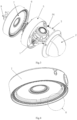
Fig.2 is a perspective view of the hemispherical camera in the embodiments of the present application; -
Fig.3 is a schematic exploded view of the hemispherical camera inFig.2 ; -
Fig.4 is a schematic view of the structure of the wire hidden case; -
Fig.5 is a partial enlarged view of portion A in the wire hidden case ofFig.4 , showing the teeth structure; -
Fig.6 is a schematic cross-sectional view of the base; -
Fig.7 is a schematic enlarged view of portion B in the base ofFig.6 ; -
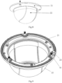
Fig. 8 is a schematic view of the structure of the upper cover component from a perspective; -
Fig.9 is a schematic view of the structure of the upper cover component from another perspective; -
Fig. 10 is a perspective view of the connecting structure between the base and the wire hidden case; -
Fig. 11 is a schematic enlarged view of portion C ofFig. 10 ; -
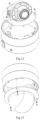
Fig. 12 is a schematic perspective view showing the installation method of the lens component; -
Fig. 13 is a schematic perspective view showing the installation method of the upper cover component; -
Fig. 14 is a schematic perspective view showing the engagement method between the pin and the teeth; -
Fig. 15 is a schematic view showing the sealing structure between the upper cover and the transparent hood; -
Fig. 16 is a schematic view showing the sealing structure between the upper cover and the base. -
- 1- lens component;
- 2- upper cover component; 21- upper cover; 22- transparent hood; 23- driving protrusion; 24- silicone plug; 25- first sealing ring;
- 3- pin; 31- head; 32- tail; 33- snap spring; 34- elastic component;
- 5- base; 51- first through hole; 52- second sealing ring;
- 6- damper;
- 7- wire hidden case; 71- teeth;
- 8- plate;
- 91- fastening screw; 92- tightening screw.
- In the drawings, the same reference signs refer to identical or similar or functionally identical elements. The embodiments of the present application will be further described in detail below with reference to the appended drawings.
- In the description of the present application, the terms "center", "longitudinal", "transversal", "front", "back", "left", "right", "vertical", "horizontal", "top", "bottom", "inside", "outside", and other indications of orientation or positional relationships are based on the orientation or positional relationships shown in the drawings. These terms are used only for the convenience of describing the present application and simplifying the description, rather than indicating or implying that the device or element must have a specific orientation, and/or be constructed and operated in a specific orientation, and therefore are not to be construed as a limitation on the scope of protection of the present application.
- As shown in
Fig. 1 , the angle adjustment of a hemisphere camera includes adjusting in three directions. After the camera is installed, the lens can be pointed at the area to be monitored through an angle adjustment mechanism in three directions. - The directions of the three-axis adjustment of the hemisphere are shown in the following figure.
- The P-direction refers to a rotation direction of which the rotation normal is perpendicular to the installation surface.
- The R-direction refers to a rotation direction of which the rotation normal coincides with the axis of the lens.
- The T-direction refers to a rotation direction where the rotation normal is perpendicular to the rotation normal of the P-direction and the rotation normal of the R-direction.
- As shown in
Figs.2 and3 , the P-direction adjustable structure of the embodiments of the present application, which is applied to a hemispherical camera, includes: anupper cover component 2, apin 3, acylindrical base 5, and a cylindrical wirehidden case 7. Thebase 5 and the wirehidden case 7 are connected to each other in a relatively rotatable manner. Theupper cover component 2 is provided with a raised part to drive thepin 3 to move from a releasing position to a locking position. In the locking position, thepin 3 locks the rotation of thebase 5 relative to the wirehidden case 7; in the releasing position,pin 3 releases the locking, allowing for a P-direction adjustment. When theupper cover component 2 is installed on thebase 5, the raised part on theupper cover component 2 drives thepin 3 to move from the releasing position to the locking position. - Specifically, as shown in
Figs.2 to 13 , the P-direction adjustable structure according to the embodiments of the present application includes: a lens component 1, anupper cover component 2, apin 3, anelastic component 34, abase 5, adamper 6, a wirehidden case 7, and aplate 8. The wirehidden case 7 and thebase 5 are arranged to rotate relative to each other. That is, a rotating gap or a rotating play exists between the wirehidden case 7 and thebase 5. - The lens component 1 can rotate vertically and axially. That is, the lens component 1 can achieve the rotation along the T-direction and R-direction.
- As shown in
Fig. 15 , theupper cover component 2 mainly includes anupper cover 21 and a hemisphericaltransparent hood 22. Theupper cover 21 and thetransparent hood 22 are fixedly connected and cannot rotate relative to each other. Afirst sealing ring 25 is arranged between theupper cover 21 and thetransparent hood 22. Theupper cover 21 and thetransparent hood 22 are pressed against each other directly or through other pieces in order to compress thefirst sealing ring 25 and achieve sealing. - The
transparent hood 22 can be completely transparent, or can be a light insulatingtransparent hood 22 with a light insulating strip or a shading part (for example, only the middle portion is arranged to be transparent). When using the hemisphere with the light insulatingtransparent hood 22 and adjusting the lens along the P-direction, thetransparent hood 22 must rotate together and remain relatively stationary with the lens; otherwise, the lens will generate interference with the light insulating strip of thetransparent hood 22. - The
upper cover component 2 is provided with a raised part for driving thepin 3. The raised part can adopt any appropriate shape and structure, which is not limited by the illustrated embodiments. - The
upper cover component 2 is installed on the base; theupper cover component 2 is provided with a raised part, which can drive thepin 3 to switch between the releasing position and the locking position; when thepin 3 is switched to the locking position, the rotational degree of freedom of thebase 5 with respect to the wire hiddencase 7 is locked; when thepin 3 is switched to the releasing position, the locking is released. - In the illustrated embodiment, the raised part is a driving
protrusion 23 arranged on theupper cover 21. The drivingprotrusion 23 is integrally formed with theupper cover 21, or is fixed on theupper cover 21 or theupper cover component 2 in other ways. When theupper cover component 2 is installed on thebase 5, the raised part onupper cover component 2 drives thepin 3 to move from the releasing position to the locking position. - The driving
protrusion 23 is used to drive thepin 3 to move from the releasing position to the locking position. In the locking position, thepin 3 locks the rotation of thebase 5 relative to the wire hiddencase 7; and in the releasing position, thepin 3 releases the locking. That is, the drivingprotrusion 23 is used for locking and releasing the relative angle between the wire hiddencase 7 and thebase 5. - In some embodiments, an elastic body is arranged on the raised part or the driving
protrusion 23, which is in contact with thepin 3 through the elastic body. Examples of the elastic body include asilicone plug 24 or a silicone cap arranged on the raised part or drivingprotrusion 23. As shown inFig. 14 , the thin rod part of thesilicone plug 24 is inserted into the central hole on the drivingprotrusion 23 in an interference fit manner, and the end of thesilicone plug 24 is pressed against the flat surface of the drivingprotrusion 23. - The
pin 3 is arranged on thebase 5 in a movable manner and has an anti detachment structure to prevent thepin 3 from falling off thebase 5. - Specifically, the
pin 3 passes through the first throughhole 51 on thebase 5. The first end of pin 3 (thetail 32 in the figures) faces (i.e. aligns with) the raised part or the drivingprotrusion 23, and the second end (head 31) faces (i.e. aligns with) a locking structure arranged on the wire hiddencase 7. As mentioned above, thepin 3 can move between the releasing position and the locking position. - In the locking position, the first end of
pin 3 engages with the locking structure on the wire hiddencase 7, thereby preventingpin 3 from rotating relative to the wire hiddencase 7. Furthermore, thebase 5 and wire hiddencase 7 are prevented from rotating relative to the wire hiddencase 7. It can be understood that after the P-direction adjustment is in place, it is necessary to keeppin 3 in the locking position. - In the releasing position, the first end of
pin 3 disengages with the locking structure on the wire hiddencase 7, thereby no longer preventingpin 3 from rotating relative to the wire hiddencase 7, in other words, allowingpin 3 to rotate relative to the wire hiddencase 7. In this case, thebase 5 and wire hiddencase 7 are allowed to rotate relative to the wire hiddencase 7. It can be understood that when a P-direction adjustment is required, it is necessary to keeppin 3 in the releasing position. - As shown in
Figs.5 to 7 , the second end ofpin 3 is thehead 31, and the first end is thetail 32. Thehead 31 is a radial expansion part, and its radial size is larger than the radial size of the rod part of thepin 3. The size and shape of thetail 32 are arranged to fit with the locking structure on the wire hiddencase 7. For example, thetail 32 is arranged in the shape of a wedge as shown in the figure to match theteeth 71 arranged in a circular array on the wire hiddencase 7. Thetail 32 can also be arranged in a conical shape to match the circular holes arranged in the circular array on the wire hiddencase 7. In an alternative embodiment, the circular holes in the circular hole array are arranged to be separated from each other. In another alternative embodiment, the circular holes in the circular hole array are arranged to locally overlap, which can provide finer accuracy of the adjustment. - As mentioned above, the
base 5 is arranged to rotate relative to the wire hiddencase 7. And thepin 3 is used to control whether thebase 5 can rotate relative to the wire hiddencase 7 for achieving the P-direction adjustment. - The
base 5 and the wire hiddencase 7 can be assembled in any appropriate way, as long as thebase 5 can rotate relative to the wire hiddencase 7. In some embodiments, the wire hiddencase 7 is fixedly installed on mounting bases such as ceilings, columns, etc. - In the illustrated embodiment, the
base 5 and the wire hiddencase 7 are assembled in the following manner. Referring toFigs. 10 and 11 , the tighteningscrew 92 passes through theplate 8 and is pressed to thebase 5, and the wire hiddencase 7 is clamped between theplate 8 and thebase 5. Thus, the assembly between thebase 5 and the wire hiddencase 7 is achieved. A gap exists between the wire hiddencase 7 and thebase 5 in an up-down direction, and a hole-shaft fit is formed at a middle portion. It can be the wire hiddencase 7 with a matching hole and thebase 5 with a matching shaft, or the wire hiddencase 7 with a matching shaft and thebase 5 with a matching hole. The relative rotation of the wire hiddencase 7 and thebase 5 is achieved or constrained by the hole-shaft fit. - A
damper 6 is arranged in the gap between the wire hiddencase 7 and thebase 5, which can generate a sense of damping during rotation. Thedamper 6 can be made of any suitable material, structure, or shape. For example, in the illustrated embodiment, twoseparate dampers 6 are provided, one being fixed relative to the wire hiddencase 7 and the other being fixed relative to thebase 5. In an alternative embodiment not shown, only onedamper 6 is provided, and thedamper 6 is only provided between the wire hiddencase 7 and thebase 5, without being fixed relative to any one of the wire hiddencase 7 and thebase 5. - As shown in
Fig.7 , thebase 5 is provided withpins 3 that can move axially. Specifically, thebase 5 is provided with a first throughhole 51. Thepin 3 is inserted into the first throughhole 51. It can be understood that thepin 3 is arranged in a gap fit manner within the first throughhole 51. Thepin 3 is restricted by an anti drop structure in thebase 5 and cannot fall out. - In the illustrated embodiment, the anti drop structure is the
snap spring 33. Thesnap spring 33 is clamped in the circular groove at thetail 32 of thepin 3, thereby preventing thepin 3 from falling off thebase 5. The outer diameter of thesnap spring 33 is greater than the diameter of the rod part of thepin 3. That is, outer diameters of thehead 31 and thesnap spring 33 are greater than a diameter of the first throughhole 51. It should be pointed out that the anti drop structure can also use any other suitable structure such as an anti drop screw, a split pin that cross thepin 3, etc. - In an initial state (a natural state), the
pin 3 is in the releasing position. For this purpose, anelastic component 34 is provided. In the embodiment ofFig.4 , theelastic component 34 is a compression spring. Specifically, theelastic component 34 is arranged between thehead 31 of thepin 3 and thebase 5, that is, the two ends of theelastic component 34 abut against thehead 31 and thebase 5, respectively. In the natural state, theelastic component 34 raises thepin 3, so that thepin 3 is in the releasing position. - In order to avoid the
pin 3 shaking inside and affecting the tightening effect, there should not be too much gap left between thepin 3 and the first throughhole 51 on thebase 5. In some embodiments, the value of the single-side gap is 0.1mm-0.3mm. For example, the single-side gap is set to be 0.2mm. - As shown in
Fig.5 , in the illustrated embodiment, the locking structure on the wire hiddencase 7 is specificallyteeth 71 arranged in a circular array. Correspondingly, thetail 32 is arranged in the shape of a wedge as shown in the figure to match the teeth on the wire hiddencase 7. The locking is achieved by inserting and fitting thetail 32 between theadjacent teeth 71. This prevents thebase 5 from rotating relative to the wire hiddencase 7. - In an alternative embodiment, the
teeth 71 are located at the radial edge position of the wire hiddencase 7. The advantage of this is that the force arm can be increased during the limit, reducing the force applied by the same torque on theteeth 71 and improving reliability. - In the illustrated embodiment, the
base 5 is directly exposed as part of the appearance of the camera. Thus, in the releasing state, thebase 5 can be directly rotated for achieving the P-direction adjustment. - In the illustrated embodiment, the lens component 1 is directly installed on the
base 5. Therefore, thebase 5 is used as a heat dissipation component and is directly exposed, greatly improving the heat dissipation efficiency compared to the technical solution where the heat dissipation component is installed inside the housing. - Specifically, the lens component 1 and the
base 5 are fixed by a screw. After being fixed, the lens component 1 and thebase 5 are relatively stationary and can rotate together relative to the wire hiddencase 7. Due to the relative stationariness of thebase 5 and theupper cover component 2, the lens component 1 is also relatively stationary relative to thetransparent hood 22. In other words, the lens component 1 is integrated with thetransparent hood 22 in the P-direction rotation. - The
upper cover 21 and thebase 5 are fixed with a screw. After being fixed, the lens component 1,base 5, and theupper cover 21 are relatively stationary. - The tightening and the loosening in the P-direction is mainly completed by three components: the wire hidden
case 7, thebase 5, and theupper cover component 2. - When the
upper cover component 2 and thebase 5 are tightened by afastening screw 91, the tightening in the P-direction is performed; when thefastening screw 91 is loosened to loosen or remove theupper cover component 2, the loosening in the P-direction is performed, allowing for achieving a P-direction adjustment. - After the assembly of the
base 5 and the wire hiddencase 7 is completed, thepin 3 on thebase 5 is located directly below or above theteeth 71 of the wire hiddencase 7. When theelastic component 34 is in the natural state, thepin 3 is raised; thepin 3 and theteeth 71 are not in contact, and the wire hiddencase 7 andbase 5 can rotate relative to each other, indicating a loosening state. - After the
upper cover component 2 and thebase 5 are tightened with a screw, due to the installation of a foolproof positioning structure between theupper cover component 2 and thebase 5, the protrusion of theupper cover component 2 will inevitably be inserted into the hole of thebase 5. The protrusion will raise thepin 3 upwards and thepin 3 is inserted into theteeth 71 of the wire hiddencase 7, thereby limiting the relative rotation of the wire hiddencase 7 and thebase 5. The elastic body on the protrusion and thepin 3 are designed with a certain amount of interference to ensure close contact between thepin 3 and theteeth 71, avoiding any gap between thepin 3 and theteeth 71 that may cause shaking. - As shown in
Fig. 16 , theupper cover component 2 and thebase 5 form one sealed chamber, and the lens component 1 is arranged in the sealed chamber. The PCB is also placed in the sealed chamber. The sealed chamber can use static sealing and waterproofing, and the sealing and waterproofing method is reliable. Asecond sealing ring 52 is arranged between theupper cover component 2 and thebase 5, and theupper cover 21 and thebase 5 are tightened with a screw to compress the silicone and achieve sealing. Theupper cover component 2 and thebase 5 are relatively fixed, forming a relatively static chamber that can be sealed statically, with reliable sealing and simple structure. - In addition, as mentioned above, the
base 5 is directly exposed, and the PCB (not shown) and lens component 1 are directly installed on thebase 5. Thebase 5 is used as a heat dissipation component and is directly exposed, which greatly improves the heat dissipation efficiency compared to the technical solution of arranging the heat dissipation component inside the housing. - In an optional embodiment of the present application, the P-direction adjustable structure includes a camera directional element, or a camera directional element is installed on the P-direction adjustable structure. Specifically, a camera directional element that rotates together with the base is installed on the
base 5, so that when performing the P-direction adjustment, the directions of the camera directional element and the lens can be adjusted simultaneously. For example, the camera directional element include a microphone, a speaker, and/or a PIR (passive infrared sensor). - Thus, when performing the P-direction angle adjustment on the lens, the
transparent hood 22 and the camera directional element can rotate together and remain relatively stationary with the lens. This solution is particularly suitable for the hemispherical camera with a light insulating transparent hood. - The tightening operation in the P-direction is very simple, as long as the
upper cover 21 is normally shut and fastened, without a redundant operation. - Another aspect of the present application proposes a hemispherical camera, including a lens component 1, an
upper cover component 2, acylindrical base 5, and a cylindrical wire hiddencase 7. Theupper cover component 2 includes a hemisphericaltransparent hood 22, which hoods the lens component 1. Thebase 5 supports the lens component 1 and theupper cover component 2, the cylindrical wire hiddencase 7 supports thebase 5, and the surface in the wire hiddencase 7 which is in contact with thebase 5 is provided with a through hole for receiving the wires of the lens component 1 through thebase 5. Wherein, the circumferential edge of the surface of the wire hiddencase 7 is provided with teeth, and the wire hiddencase 7 is defined such that: when the wire hiddencase 7 is in non-fastened connection with thebase 5, thebase 5 can drive the lens component 1 and the wire hiddencase 7 to rotate in the P-direction, so that the lens component 1 rotates to a preset angle; and when the wire hiddencase 7 is in fastened connection with thebase 5, the teeth of the wire hiddencase 7 prevent thebase 5 from rotating in the P-direction, so that the lens component 1 is defined at the preset angle. - The
upper cover component 2 includes a hemisphericaltransparent hood 22, which hoods the lens component 1. For example, thetransparent hood 22 can be completely transparent, or can be a light insulatingtransparent hood 22 with a light insulating strip or a shading part, for example, only the middle portion is arranged to be transparent. When using the hemisphere with the light insulatingtransparent hood 22 and adjusting the lens along P-direction, thetransparent hood 22 must rotate together and remain relatively stationary with the lens; otherwise, the lens will generate interference with the light insulating strip of thetransparent hood 22. - The wire hidden
case 7 and thebase 5 are arranged to rotate relative to each other. That is, a rotating gap or a rotating play exists between the wire hiddencase 7 and thebase 5. A surface of the wire hiddencase 7 in contact with thebase 5 is provided with a through hole for receiving the wires of the lens component 1 through thebase 5. In an alternative embodiment, theteeth 71 are located at the radial edge position of the wire hiddencase 7. The advantage of this is that the force arm can be increased during the limit, reducing the force applied by the same torque on theteeth 71 and improving reliability. - When the wire hidden
case 7 is in non-fastened connection with thebase 5, thebase 5 can drive the lens component 1 and the wire hiddencase 7 to rotate in the P-direction, so that the lens component 1 rotates to a preset angle. When the wire hiddencase 7 is in fastened connection with thebase 5, theteeth 71 of the wire hiddencase 7 prevent thebase 5 from rotating in the P-direction, so that the lens component 1 is defined at the preset angle. - The
base 5 and the wire hiddencase 7 have the same first axis, and the rotating in the P-direction refers to a horizontal rotation around the first axis. - The hemispherical camera also includes a
pin 3. When thepin 3 comes into contact with theteeth 71, the wire hiddencase 7 is in fastened connection with thebase 5. When thepin 3 is loosened from theteeth 71, the wire hiddencase 7 is in non-fastened connection with thebase 5. - As shown in
Fig.7 , thepin 3 is in contact with theteeth 71 to enable thebase 5 and wire hiddencase 7 to switch between a fastened connection state and a non-fastened connection state. In the initial/natural state, thepin 3 is in the releasing position. For this purpose, anelastic component 34 is provided. In the embodiment ofFig.4 , theelastic component 34 is a compression spring. Specifically, theelastic component 34 is arranged between thehead 31 of thepin 3 and thebase 5, that is, two ends of theelastic component 34 abut against thehead 31 and thebase 5, respectively. In the natural state, theelastic component 34 raises thepin 3, so that thepin 3 is in the releasing position. - In order to avoid the
pin 3 shaking inside and affecting the tightening effect, there should not be too much gap left between thepin 3 and the first throughhole 51 on thebase 5. In some embodiments, the value of the single-side gap is 0.1mm-0.3mm. For example, the single-side gap is set to be 0.2mm. - As shown in
Fig.5 , in the illustrated embodiment, theteeth 71 on the wire hiddencase 7 are arranged in a circular array. Correspondingly, thetail 32 is arranged in the shape of a wedge as shown in the figure to match the teeth on the wire hiddencase 7. The locking is achieved by inserting and fitting thetail 32 between theadjacent teeth 71. This prevents thebase 5 from rotating relative to the wire hiddencase 7. - The
pin 3 runs parallel to the first axis through thebase 5. - As shown in
Fig.7 , thebase 5 is provided with thepin 3 that can move axially. Specifically, thebase 5 is provided with a first throughhole 51. Thepin 3 is inserted into the first throughhole 51. It can be understood that thepin 3 is arranged in a gap fit manner within the first through hole 51.Thepin 3 is restricted by an anti drop structure in thebase 5 and cannot fall out. - In the illustrated embodiment, the anti drop structure is the
snap spring 33. Thesnap spring 33 is clamped in the circular groove at thetail 32 of thepin 3, thereby preventing thepin 3 from falling off thebase 5. The outer diameter of thesnap spring 33 is greater than the diameter of the rod part of thepin 3. That is, outer diameters of thehead 31 and thesnap spring 33 are greater than a diameter of the first throughhole 51. It should be pointed out that the anti drop structure can also use any other suitable structure such as an anti drop screw, a split pin that cross thepin 3, etc. - In the illustrated embodiment, the
base 5 and the wire hiddencase 7 are assembled in the following manner. Referring toFigs. 10 and 11 , the tighteningscrew 92 passes through theplate 8 and is pressed to thebase 5, and the wire hiddencase 7 is clamped between theplate 8 and thebase 5. Thus, the assembly between thebase 5 and the wire hiddencase 7 is achieved. A gap exists between the wire hiddencase 7 and thebase 5 in an up-down direction, and a hole-shaft fit is formed at a middle portion. It can be the wire hiddencase 7 with a matching hole and thebase 5 with a matching shaft, or the wire hiddencase 7 with a matching shaft and thebase 5 with a matching hole. The relative rotation of the wire hiddencase 7 and thebase 5 is achieved or constrained by the hole-shaft fit. - When the
upper cover component 2 is in non-fastened connection with thebase 5, thepin 3 is loose from the teeth. When theupper cover component 2 is in fastened connection with thebase 5, thepin 3 contacts theteeth 71. - The edge of
upper cover component 2 includes a raised part, which extends towards thebase 5. When theupper cover component 2 is in fastened connection with thebase 5, thepin 3 is subjected to pressure applied by the raised part to contact thepin 3 with theteeth 71. - The
upper cover component 2 is provided with a raised part for driving thepin 3. The raised part can adopt any appropriate shape and structure, which is not limited by the illustrated embodiments. - The
upper cover component 2 is installed on the base; theupper cover component 2 is provided with a raised part, which can drive thepin 3 to switch between the releasing position and the locking position; when thepin 3 is switched to the locking position, the rotational degree of freedom of thebase 5 and the wire hiddencase 7 is locked; when thepin 3 is switched to the releasing position, the locking is released. - In the illustrated embodiment, the raised part is a driving
protrusion 23 arranged on theupper cover 21. The drivingprotrusion 23 is integrally formed with theupper cover component 21, or is fixed on theupper cover 21 or theupper cover component 2 in other ways. When theupper cover component 2 is installed on thebase 5, the raised part onupper cover component 2 drives thepin 3 to move from the releasing position to the locking position. - The hemispherical camera also includes an elastic component, which sleeves the
pin 3 to enable thepin 3 to move in a direction parallel to the first axis when subjected to or not subjected to pressure applied by the raised part. - As shown in
Fig.7 , thebase 5 is provided withpins 3 that can move axially. Specifically, thebase 5 is provided with a first throughhole 51. Thepin 3 is inserted into the first throughhole 51. It can be understood thatpin 3 is arranged in a gap fit manner within the first throughhole 51. The elastic component sleeves thepin 3 to enablepin 3 to move in a direction parallel to the first axis when subjected to or not subjected to pressure applied by the raised part. In the illustrated example, theelastic component 34 is a compression spring. Specifically, theelastic component 34 is arranged between thehead 31 of thepin 3 and thebase 5, that is, two ends of theelastic component 34 abut against thehead 31 and thebase 5, respectively. In the natural state, theelastic component 34 raises thepin 3, so that thepin 3 is located in the releasing position. - In order to avoid the
pin 3 shaking inside and affecting the locking effect, there should not be too much gap left between thepin 3 and the first throughhole 51 on thebase 5. In some embodiments, the value of the single-side gap is 0.1mm-0.3mm. For example, the single-side gap is set to be 0.2mm. - The
upper cover component 2 and thebase 5 are tightened and fastened by a screw. - As shown in
Fig.9 , when theupper cover component 2 and thebase 5 are tightened with thefastening screw 91, the tightening in the P-direction is performed; when thefastening screw 91 is loosened to loosen or remove theupper cover component 2, the loosening in the P-direction is performed, allowing for achieving the P-direction adjustment. - The lens component 1 can rotate in a pitch direction.
- A camera directional element can be installed on the lens component 1. Specifically, a camera directional element that rotates together with the base is installed on
base 5, so that during performing the P-direction adjustment, the direction of the camera directional element and the lens can be adjusted simultaneously. For example, the camera directional element includes a microphone, a speaker, and/or a PIR passive infrared sensor. - Thus, when performing the P-direction angle adjustment on the lens, the
transparent hood 22 and the camera directional element can rotate together and remain relatively stationary with the lens. Finally, it should be pointed out that the above embodiments are only used to illustrate the technical solution of the present application, and not to limit it. An ordinary skilled person in the art should understand that the technical solutions recorded in the aforementioned embodiments can be modified, or some of the technical features can be equivalently replaced; these modifications or replacements do not separate the essence of the corresponding technical solutions from the spirit and scope of the embodiments of the present application.
Claims (22)
- A P-direction adjustable structure, which is applied to a hemispherical camera, comprising an upper cover component (2), a pin (3), a cylindrical base (5), and a cylindrical wire hidden case (7);wherein, the base (5) is rotatably connected to the wire hidden case (7);the upper cover component (2) is installed on the base (5); the upper cover component (2) is provided with a raised part, which can drive the pin (3) to switch between a releasing position and a locking position;wherein, when the pin (3) is switched to the locking position, a rotational degree of freedom of the base (5) with respect to the wire hidden case (7) is locked; when the pin (3) is switched to the releasing position, locking is released.
- The P-direction adjustable structure as claimed in claim 1, wherein, the pin (3) passes through a first through hole (51) on the base (5); a first end of the pin (3) faces the raised part, and a second end of the pin (3) faces a locking structure arranged on the wire hidden case (7); the raised part acts on the first end of the pin (3), so that the second end of the pin (3) is engaged with the locking structure.
- The P-direction adjustable structure as claimed in claim 2, wherein, the first end of the pin (3) is a head (31) of the pin (3), and the second end of the pin (3) is a tail (32) of the pin (3);
a snap spring (33) is arranged at an axial position of the pin (3) adjacent to the tail (32), and outer diameters of the head (31) and the snap spring (33) are greater than a diameter of the first through hole (51). - The P-direction adjustable structure as claimed in claim 3, wherein, an elastic component (34) is arranged between the head (31) of the pin (3) and the base (5);
two ends of the elastic component (34) abut against the head (31) and the base (5), respectively, and the elastic component (34), when in a natural state, enables the pin (3) to be in the releasing position. - The P-direction adjustable structure as claimed in claim 2, wherein, a single-side gap between the pin (3) and the first through hole (51) is within the range of 0. 1mm-0.3mm.
- The P-direction adjustable structure as claimed in claim 2, wherein, the locking structure on the wire hidden case (7) is teeth (71) arranged in a circular array, and the teeth (71) are arranged at the radial edge position of the wire hidden case (7).
- The P-direction adjustable structure as claimed in claim 1, wherein, the base (5) is directly exposed;
the upper cover component (2) and the base (5) form one sealed chamber. - The P-direction adjustable structure as claimed in claim 1, wherein, the raised part arranged on the upper cover component (2) is a driving protrusion (23).
- The P-direction adjustable structure as claimed in claim 8, wherein, an elastic body is arranged on the driving protrusion (23), and the driving protrusion (23) contacts the pin (3) through the elastic body.
- The P-direction adjustable structure as claimed in claim 1, wherein, a gap exists between the wire hidden case (7) and the base (5) in an up-down direction, and a hole-shaft fit is formed at a middle portion.
- The P-direction adjustable structure as claimed in claim 10, wherein, a damper (6) is arranged between the wire hidden case (7) and the base (5).
- The P-direction adjustable structure as claimed in claim 1, wherein, a camera directional element is installed on the base (5) and rotates with the base; the camera directional element is configured to synchronously adjust directions of the camera directional element and a lens of the hemispherical camera when performing a P-direction adjustment.
- A hemispherical camera, comprising the P-direction adjustable structure as claimed in any one of claims 1 to 12.
- A hemispherical camera, comprising:a lens component (1);an upper cover component (2) comprising a hemispherical transparent hood (22), which hoods the lens component (1);a cylindrical base (5) supporting the lens component (1) and the upper cover component (2);a cylindrical wire hidden case (7) supporting the base (5), wherein a surface of the wire hidden case (7) in contact with the base (5) is provided with a through hole for receiving a wire of the lens component (1) through the base (5);wherein, a circumferential edge of the surface of the wire hidden case (7) is provided with teeth (71), and the wire hidden case (7) is defined such that:when the wire hidden case (7) is in non-fastened connection with the base (5), the base (5) can drive the lens component (1) and the wire hidden case (7) to rotate in the P-direction, so that the lens component (1) rotates to a preset angle;when the wire hidden case (7) is in fastened connection with the base (5), the teeth (71) of the wire hidden case (7) prevent the base (5) from rotating in the P-direction, so that the lens component (1) is defined at the preset angle.
- The hemispherical camera as claimed in claim 14, wherein,the base (5) and the wire hidden case (7) have a same first axis;the rotating in the P-direction refers to a horizontal rotation around the first axis.
- The hemispherical camera as claimed in claim 15, wherein,the hemispherical camera also comprises a pin (3);when the pin (3) contacts the teeth (71), the wire hidden case (7) is in fastened connection with the base (5);when the pin (3) is loosened from the teeth (71), the wire hidden case (7) is in non-fastened connection with the base (5).
- The hemispherical camera as claimed in claim 16, wherein, the pin (3) passes through the base (5) along a direction parallel to the first axis.
- The hemispherical camera as claimed in claim 17, wherein,when the upper cover component (2) is in non-fastened connection with the base (5), the pin (3) is loosened from the teeth (71);when the upper cover component (2) is in fastened connection with the base (5), the pin (3) contacts the teeth (71).
- The hemispherical camera as claimed in claim 18, wherein,an edge of the upper cover component (2) comprises a raised part, which extends towards the base (5);when the upper cover component (2) is in fastened connection with the base (5), the pin (3) is subjected to a pressure applied by the raised part so that the pin (3) contacts the teeth (71).
- The hemispherical camera as claimed in claim 19, wherein, the hemispherical camera also comprises an elastic component (34), which sleeves the pin (3), so that the pin (3) can move along a direction parallel to the first axis when subjected to or not subjected to the pressure applied by the raised part.
- The hemispherical camera as claimed in claim 19, wherein,
the upper cover component (2) is tightened and fastened with the base (5) by a screw. - The hemispherical camera as claimed in any one of claims 14 to 21, wherein, the lens component (1) can rotate in a pitch direction.
Applications Claiming Priority (2)
| Application Number | Priority Date | Filing Date | Title |
|---|---|---|---|
| CN202110168516.7A CN113055564B (en) | 2021-02-07 | 2021-02-07 | Hemispherical camera P-direction adjusting structure |
| PCT/CN2021/143569 WO2022166498A1 (en) | 2021-02-07 | 2021-12-31 | P-direction adjusting structure and dome camera |
Publications (3)
| Publication Number | Publication Date |
|---|---|
| EP4239998A1 true EP4239998A1 (en) | 2023-09-06 |
| EP4239998A4 EP4239998A4 (en) | 2024-03-20 |
| EP4239998B1 EP4239998B1 (en) | 2025-07-30 |
Family
ID=76508736
Family Applications (1)
| Application Number | Title | Priority Date | Filing Date |
|---|---|---|---|
| EP21924491.0A Active EP4239998B1 (en) | 2021-02-07 | 2021-12-31 | P-direction adjusting structure and dome camera |
Country Status (3)
| Country | Link |
|---|---|
| EP (1) | EP4239998B1 (en) |
| CN (1) | CN113055564B (en) |
| WO (1) | WO2022166498A1 (en) |
Families Citing this family (2)
| Publication number | Priority date | Publication date | Assignee | Title |
|---|---|---|---|---|
| CN113055564B (en) * | 2021-02-07 | 2023-07-25 | 杭州海康威视数字技术股份有限公司 | Hemispherical camera P-direction adjusting structure |
| CN118803438B (en) * | 2024-09-11 | 2024-12-10 | 杭州海康威视数字技术股份有限公司 | Binocular camera |
Family Cites Families (29)
| Publication number | Priority date | Publication date | Assignee | Title |
|---|---|---|---|---|
| JP2002340282A (en) * | 2001-05-14 | 2002-11-27 | Sony Corp | Product mounting structure on the wall |
| JP3821696B2 (en) * | 2001-12-07 | 2006-09-13 | 帝国通信工業株式会社 | Multiple rotary electronic components |
| CN2624550Y (en) * | 2003-06-20 | 2004-07-07 | 深圳市宏天智电子有限公司 | Flying-saucer UFO type hemisphere video camera |
| US7217045B2 (en) * | 2005-01-03 | 2007-05-15 | Robert Bosch Gmbh | Connect/disconnect mechanism for a surveillance camera head |
| JP4152980B2 (en) * | 2005-10-14 | 2008-09-17 | 松下電器産業株式会社 | Dome camera |
| JP2009134107A (en) * | 2007-11-30 | 2009-06-18 | Sony Corp | Imaging device |
| KR100950733B1 (en) * | 2008-05-08 | 2010-04-01 | (주)씨프로 | Supporting Device for Camera Module |
| CN201251672Y (en) * | 2008-09-08 | 2009-06-03 | 杭州海康威视数字技术股份有限公司 | Universal regulation device for a semi-spherical camera |
| EP2287662B1 (en) * | 2008-09-09 | 2013-05-29 | Panasonic Corporation | Dome camera |
| CN201788348U (en) * | 2010-09-09 | 2011-04-06 | 吉多思实业(深圳)有限公司 | Pan-tilt head switching mechanism |
| KR20130016672A (en) * | 2011-08-08 | 2013-02-18 | 삼성테크윈 주식회사 | Monitoring camera |
| CN102333187B (en) * | 2011-09-29 | 2013-04-10 | 旗瀚科技有限公司 | Fixed hemisphere camera |
| WO2013121880A1 (en) * | 2012-02-14 | 2013-08-22 | 富士フイルム株式会社 | Dome-shaped camera |
| KR101252748B1 (en) * | 2012-09-27 | 2013-04-09 | 에치디프로 주식회사 | Lens adjusting device of guard dome type camera |
| JP6283909B2 (en) * | 2013-03-01 | 2018-02-28 | パナソニックIpマネジメント株式会社 | Camera device and method of controlling camera device |
| CN203522874U (en) * | 2013-09-05 | 2014-04-02 | 动力盈科实业(深圳)有限公司 | Sliding type semi-spherical camera |
| CN203656513U (en) * | 2013-11-01 | 2014-06-18 | 深圳中兴力维技术有限公司 | Triaxial steering cradle head structure and camera adopting same |
| JP6179817B2 (en) * | 2014-09-24 | 2017-08-16 | パナソニックIpマネジメント株式会社 | Imaging device |
| JP6739278B2 (en) * | 2016-08-05 | 2020-08-12 | キヤノン株式会社 | Electronic equipment and monitoring system |
| CN206100238U (en) * | 2016-10-25 | 2017-04-12 | 杭州海康威视数字技术股份有限公司 | Take photograph camera installation device and take photograph camera |
| CN206398296U (en) * | 2016-12-20 | 2017-08-11 | 浙江大华技术股份有限公司 | A kind of camera mount and video camera |
| CN207150701U (en) * | 2017-06-08 | 2018-03-27 | 杭州海康威视数字技术股份有限公司 | Spherical camera |
| CN206875068U (en) * | 2017-06-16 | 2018-01-12 | 杭州海康威视数字技术股份有限公司 | A kind of video camera regulating mechanism |
| CN107404610B (en) * | 2017-07-31 | 2019-10-15 | 重庆三朵蜜生物技术有限公司 | Dome-type camera with adjustable visual range direction |
| CN207830867U (en) * | 2017-12-12 | 2018-09-07 | 杭州海康威视数字技术股份有限公司 | A kind of video camera |
| KR101875583B1 (en) * | 2018-05-09 | 2018-07-09 | 주식회사 씨티에스시스템 | Apparatus for 3 axis dome type of security camera |
| CN212343868U (en) * | 2020-03-20 | 2021-01-12 | 浙江大华技术股份有限公司 | Dome camera |
| CN212251866U (en) * | 2020-06-08 | 2020-12-29 | 苏州科达科技股份有限公司 | Pan-tilt camera assembly and pan-tilt camera installation assembly |
| CN113055564B (en) * | 2021-02-07 | 2023-07-25 | 杭州海康威视数字技术股份有限公司 | Hemispherical camera P-direction adjusting structure |
-
2021
- 2021-02-07 CN CN202110168516.7A patent/CN113055564B/en active Active
- 2021-12-31 EP EP21924491.0A patent/EP4239998B1/en active Active
- 2021-12-31 WO PCT/CN2021/143569 patent/WO2022166498A1/en not_active Ceased
Also Published As
| Publication number | Publication date |
|---|---|
| EP4239998B1 (en) | 2025-07-30 |
| EP4239998A4 (en) | 2024-03-20 |
| WO2022166498A1 (en) | 2022-08-11 |
| CN113055564A (en) | 2021-06-29 |
| CN113055564B (en) | 2023-07-25 |
Similar Documents
| Publication | Publication Date | Title |
|---|---|---|
| EP4239998B1 (en) | P-direction adjusting structure and dome camera | |
| KR102364279B1 (en) | Multi-lens camera and lens adjuster | |
| EP3490239B1 (en) | Spherical video camera | |
| EP3726119A1 (en) | Video camera | |
| CN103925530B (en) | A kind of rotating LED shot-light and assemble method thereof | |
| KR20010111761A (en) | a camera mechanism watching a specific area | |
| CN109451227A (en) | A kind of video camera | |
| CN206093722U (en) | Fixed lamps and lanterns of rotation type and link plate subassembly | |
| CN108696689B (en) | Camera structure and security protection wall lamp | |
| KR200180585Y1 (en) | A safety-camera which is able to control photographying angle | |
| CN114598795B (en) | A monitoring device | |
| CN206268924U (en) | Corner lights | |
| JP4709781B2 (en) | Case structure of outdoor equipment | |
| CN209294955U (en) | Slim Rotating LED Downlight | |
| CN218217345U (en) | Bluetooth receiver | |
| KR200217796Y1 (en) | a camera mechanism watching a specific area | |
| JP4492141B2 (en) | Remote control device | |
| CN207442055U (en) | A kind of electrical connector housing | |
| CN115723111B (en) | Adjusting positioning components, camera mechanism, and robot | |
| CN214756566U (en) | Dome camera | |
| CN219036160U (en) | Convenient strutting arrangement | |
| KR200196449Y1 (en) | The perspective window of door which is able to control the angle freely | |
| CN215734697U (en) | Home theater sound system that is easy to assemble and disassemble | |
| CN211236532U (en) | Photography luminaire with built-in shading structure | |
| CN213983416U (en) | PC lampshade |
Legal Events
| Date | Code | Title | Description |
|---|---|---|---|
| STAA | Information on the status of an ep patent application or granted ep patent |
Free format text: STATUS: THE INTERNATIONAL PUBLICATION HAS BEEN MADE |
|
| PUAI | Public reference made under article 153(3) epc to a published international application that has entered the european phase |
Free format text: ORIGINAL CODE: 0009012 |
|
| STAA | Information on the status of an ep patent application or granted ep patent |
Free format text: STATUS: REQUEST FOR EXAMINATION WAS MADE |
|
| 17P | Request for examination filed |
Effective date: 20230601 |
|
| AK | Designated contracting states |
Kind code of ref document: A1 Designated state(s): AL AT BE BG CH CY CZ DE DK EE ES FI FR GB GR HR HU IE IS IT LI LT LU LV MC MK MT NL NO PL PT RO RS SE SI SK SM TR |
|
| REG | Reference to a national code |
Ref legal event code: R079 Free format text: PREVIOUS MAIN CLASS: H04N0005225000 Ipc: H04N0023510000 Ref country code: DE Ref document number: 602021035371 Country of ref document: DE |
|
| A4 | Supplementary search report drawn up and despatched |
Effective date: 20240219 |
|
| RIC1 | Information provided on ipc code assigned before grant |
Ipc: G08B 13/196 20060101ALI20240213BHEP Ipc: H04N 23/52 20230101ALI20240213BHEP Ipc: H04N 23/51 20230101AFI20240213BHEP |
|
| DAV | Request for validation of the european patent (deleted) | ||
| DAX | Request for extension of the european patent (deleted) | ||
| GRAP | Despatch of communication of intention to grant a patent |
Free format text: ORIGINAL CODE: EPIDOSNIGR1 |
|
| STAA | Information on the status of an ep patent application or granted ep patent |
Free format text: STATUS: GRANT OF PATENT IS INTENDED |
|
| INTG | Intention to grant announced |
Effective date: 20250314 |
|
| GRAS | Grant fee paid |
Free format text: ORIGINAL CODE: EPIDOSNIGR3 |
|
| GRAA | (expected) grant |
Free format text: ORIGINAL CODE: 0009210 |
|
| STAA | Information on the status of an ep patent application or granted ep patent |
Free format text: STATUS: THE PATENT HAS BEEN GRANTED |
|
| AK | Designated contracting states |
Kind code of ref document: B1 Designated state(s): AL AT BE BG CH CY CZ DE DK EE ES FI FR GB GR HR HU IE IS IT LI LT LU LV MC MK MT NL NO PL PT RO RS SE SI SK SM TR |
|
| REG | Reference to a national code |
Ref country code: GB Ref legal event code: FG4D |
|
| REG | Reference to a national code |
Ref country code: CH Ref legal event code: EP |
|
| REG | Reference to a national code |
Ref country code: DE Ref legal event code: R096 Ref document number: 602021035371 Country of ref document: DE |
|
| REG | Reference to a national code |
Ref country code: IE Ref legal event code: FG4D |
|
| REG | Reference to a national code |
Ref country code: NL Ref legal event code: MP Effective date: 20250730 |
|
| REG | Reference to a national code |
Ref country code: AT Ref legal event code: MK05 Ref document number: 1820370 Country of ref document: AT Kind code of ref document: T Effective date: 20250730 |
|
| PG25 | Lapsed in a contracting state [announced via postgrant information from national office to epo] |
Ref country code: PT Free format text: LAPSE BECAUSE OF FAILURE TO SUBMIT A TRANSLATION OF THE DESCRIPTION OR TO PAY THE FEE WITHIN THE PRESCRIBED TIME-LIMIT Effective date: 20251202 |
|
| PG25 | Lapsed in a contracting state [announced via postgrant information from national office to epo] |
Ref country code: IS Free format text: LAPSE BECAUSE OF FAILURE TO SUBMIT A TRANSLATION OF THE DESCRIPTION OR TO PAY THE FEE WITHIN THE PRESCRIBED TIME-LIMIT Effective date: 20251130 |
|
| PGFP | Annual fee paid to national office [announced via postgrant information from national office to epo] |
Ref country code: GB Payment date: 20251229 Year of fee payment: 5 |
|
| PG25 | Lapsed in a contracting state [announced via postgrant information from national office to epo] |
Ref country code: NO Free format text: LAPSE BECAUSE OF FAILURE TO SUBMIT A TRANSLATION OF THE DESCRIPTION OR TO PAY THE FEE WITHIN THE PRESCRIBED TIME-LIMIT Effective date: 20251030 |
|
| REG | Reference to a national code |
Ref country code: LT Ref legal event code: MG9D |
|
| PG25 | Lapsed in a contracting state [announced via postgrant information from national office to epo] |
Ref country code: AT Free format text: LAPSE BECAUSE OF FAILURE TO SUBMIT A TRANSLATION OF THE DESCRIPTION OR TO PAY THE FEE WITHIN THE PRESCRIBED TIME-LIMIT Effective date: 20250730 |
|
| PG25 | Lapsed in a contracting state [announced via postgrant information from national office to epo] |
Ref country code: FI Free format text: LAPSE BECAUSE OF FAILURE TO SUBMIT A TRANSLATION OF THE DESCRIPTION OR TO PAY THE FEE WITHIN THE PRESCRIBED TIME-LIMIT Effective date: 20250730 |
|
| PG25 | Lapsed in a contracting state [announced via postgrant information from national office to epo] |
Ref country code: HR Free format text: LAPSE BECAUSE OF FAILURE TO SUBMIT A TRANSLATION OF THE DESCRIPTION OR TO PAY THE FEE WITHIN THE PRESCRIBED TIME-LIMIT Effective date: 20250730 Ref country code: NL Free format text: LAPSE BECAUSE OF FAILURE TO SUBMIT A TRANSLATION OF THE DESCRIPTION OR TO PAY THE FEE WITHIN THE PRESCRIBED TIME-LIMIT Effective date: 20250730 |
|
| PG25 | Lapsed in a contracting state [announced via postgrant information from national office to epo] |
Ref country code: GR Free format text: LAPSE BECAUSE OF FAILURE TO SUBMIT A TRANSLATION OF THE DESCRIPTION OR TO PAY THE FEE WITHIN THE PRESCRIBED TIME-LIMIT Effective date: 20251031 |
|
| PG25 | Lapsed in a contracting state [announced via postgrant information from national office to epo] |
Ref country code: SE Free format text: LAPSE BECAUSE OF FAILURE TO SUBMIT A TRANSLATION OF THE DESCRIPTION OR TO PAY THE FEE WITHIN THE PRESCRIBED TIME-LIMIT Effective date: 20250730 |
|
| PG25 | Lapsed in a contracting state [announced via postgrant information from national office to epo] |
Ref country code: LV Free format text: LAPSE BECAUSE OF FAILURE TO SUBMIT A TRANSLATION OF THE DESCRIPTION OR TO PAY THE FEE WITHIN THE PRESCRIBED TIME-LIMIT Effective date: 20250730 |
|
| PG25 | Lapsed in a contracting state [announced via postgrant information from national office to epo] |
Ref country code: BG Free format text: LAPSE BECAUSE OF FAILURE TO SUBMIT A TRANSLATION OF THE DESCRIPTION OR TO PAY THE FEE WITHIN THE PRESCRIBED TIME-LIMIT Effective date: 20250730 Ref country code: PL Free format text: LAPSE BECAUSE OF FAILURE TO SUBMIT A TRANSLATION OF THE DESCRIPTION OR TO PAY THE FEE WITHIN THE PRESCRIBED TIME-LIMIT Effective date: 20250730 |
|
| PG25 | Lapsed in a contracting state [announced via postgrant information from national office to epo] |
Ref country code: RS Free format text: LAPSE BECAUSE OF FAILURE TO SUBMIT A TRANSLATION OF THE DESCRIPTION OR TO PAY THE FEE WITHIN THE PRESCRIBED TIME-LIMIT Effective date: 20251030 |
|
| PG25 | Lapsed in a contracting state [announced via postgrant information from national office to epo] |
Ref country code: ES Free format text: LAPSE BECAUSE OF FAILURE TO SUBMIT A TRANSLATION OF THE DESCRIPTION OR TO PAY THE FEE WITHIN THE PRESCRIBED TIME-LIMIT Effective date: 20250730 |
|
| PG25 | Lapsed in a contracting state [announced via postgrant information from national office to epo] |
Ref country code: RO Free format text: LAPSE BECAUSE OF FAILURE TO SUBMIT A TRANSLATION OF THE DESCRIPTION OR TO PAY THE FEE WITHIN THE PRESCRIBED TIME-LIMIT Effective date: 20250730 |
|
| PG25 | Lapsed in a contracting state [announced via postgrant information from national office to epo] |
Ref country code: SM Free format text: LAPSE BECAUSE OF FAILURE TO SUBMIT A TRANSLATION OF THE DESCRIPTION OR TO PAY THE FEE WITHIN THE PRESCRIBED TIME-LIMIT Effective date: 20250730 |
|
| PG25 | Lapsed in a contracting state [announced via postgrant information from national office to epo] |
Ref country code: DK Free format text: LAPSE BECAUSE OF FAILURE TO SUBMIT A TRANSLATION OF THE DESCRIPTION OR TO PAY THE FEE WITHIN THE PRESCRIBED TIME-LIMIT Effective date: 20250730 |
|
| PG25 | Lapsed in a contracting state [announced via postgrant information from national office to epo] |
Ref country code: IT Free format text: LAPSE BECAUSE OF FAILURE TO SUBMIT A TRANSLATION OF THE DESCRIPTION OR TO PAY THE FEE WITHIN THE PRESCRIBED TIME-LIMIT Effective date: 20250730 |
|
| PG25 | Lapsed in a contracting state [announced via postgrant information from national office to epo] |
Ref country code: CZ Free format text: LAPSE BECAUSE OF FAILURE TO SUBMIT A TRANSLATION OF THE DESCRIPTION OR TO PAY THE FEE WITHIN THE PRESCRIBED TIME-LIMIT Effective date: 20250730 |
|
| PG25 | Lapsed in a contracting state [announced via postgrant information from national office to epo] |
Ref country code: EE Free format text: LAPSE BECAUSE OF FAILURE TO SUBMIT A TRANSLATION OF THE DESCRIPTION OR TO PAY THE FEE WITHIN THE PRESCRIBED TIME-LIMIT Effective date: 20250730 Ref country code: SK Free format text: LAPSE BECAUSE OF FAILURE TO SUBMIT A TRANSLATION OF THE DESCRIPTION OR TO PAY THE FEE WITHIN THE PRESCRIBED TIME-LIMIT Effective date: 20250730 |