EP3726119A1 - Video camera - Google Patents
Video camera Download PDFInfo
- Publication number
- EP3726119A1 EP3726119A1 EP18889640.1A EP18889640A EP3726119A1 EP 3726119 A1 EP3726119 A1 EP 3726119A1 EP 18889640 A EP18889640 A EP 18889640A EP 3726119 A1 EP3726119 A1 EP 3726119A1
- Authority
- EP
- European Patent Office
- Prior art keywords
- assembly
- teeth
- lens assembly
- shell assembly
- base
- Prior art date
- Legal status (The legal status is an assumption and is not a legal conclusion. Google has not performed a legal analysis and makes no representation as to the accuracy of the status listed.)
- Pending
Links
Images


Classifications
-
- F—MECHANICAL ENGINEERING; LIGHTING; HEATING; WEAPONS; BLASTING
- F16—ENGINEERING ELEMENTS AND UNITS; GENERAL MEASURES FOR PRODUCING AND MAINTAINING EFFECTIVE FUNCTIONING OF MACHINES OR INSTALLATIONS; THERMAL INSULATION IN GENERAL
- F16M—FRAMES, CASINGS OR BEDS OF ENGINES, MACHINES OR APPARATUS, NOT SPECIFIC TO ENGINES, MACHINES OR APPARATUS PROVIDED FOR ELSEWHERE; STANDS; SUPPORTS
- F16M11/00—Stands or trestles as supports for apparatus or articles placed thereon Stands for scientific apparatus such as gravitational force meters
- F16M11/02—Heads
- F16M11/04—Means for attachment of apparatus; Means allowing adjustment of the apparatus relatively to the stand
- F16M11/06—Means for attachment of apparatus; Means allowing adjustment of the apparatus relatively to the stand allowing pivoting
- F16M11/10—Means for attachment of apparatus; Means allowing adjustment of the apparatus relatively to the stand allowing pivoting around a horizontal axis
-
- H—ELECTRICITY
- H04—ELECTRIC COMMUNICATION TECHNIQUE
- H04N—PICTORIAL COMMUNICATION, e.g. TELEVISION
- H04N23/00—Cameras or camera modules comprising electronic image sensors; Control thereof
- H04N23/60—Control of cameras or camera modules
- H04N23/695—Control of camera direction for changing a field of view, e.g. pan, tilt or based on tracking of objects
-
- F—MECHANICAL ENGINEERING; LIGHTING; HEATING; WEAPONS; BLASTING
- F16—ENGINEERING ELEMENTS AND UNITS; GENERAL MEASURES FOR PRODUCING AND MAINTAINING EFFECTIVE FUNCTIONING OF MACHINES OR INSTALLATIONS; THERMAL INSULATION IN GENERAL
- F16M—FRAMES, CASINGS OR BEDS OF ENGINES, MACHINES OR APPARATUS, NOT SPECIFIC TO ENGINES, MACHINES OR APPARATUS PROVIDED FOR ELSEWHERE; STANDS; SUPPORTS
- F16M11/00—Stands or trestles as supports for apparatus or articles placed thereon Stands for scientific apparatus such as gravitational force meters
- F16M11/02—Heads
- F16M11/18—Heads with mechanism for moving the apparatus relatively to the stand
-
- F—MECHANICAL ENGINEERING; LIGHTING; HEATING; WEAPONS; BLASTING
- F16—ENGINEERING ELEMENTS AND UNITS; GENERAL MEASURES FOR PRODUCING AND MAINTAINING EFFECTIVE FUNCTIONING OF MACHINES OR INSTALLATIONS; THERMAL INSULATION IN GENERAL
- F16M—FRAMES, CASINGS OR BEDS OF ENGINES, MACHINES OR APPARATUS, NOT SPECIFIC TO ENGINES, MACHINES OR APPARATUS PROVIDED FOR ELSEWHERE; STANDS; SUPPORTS
- F16M11/00—Stands or trestles as supports for apparatus or articles placed thereon Stands for scientific apparatus such as gravitational force meters
- F16M11/20—Undercarriages with or without wheels
- F16M11/2007—Undercarriages with or without wheels comprising means allowing pivoting adjustment
- F16M11/2014—Undercarriages with or without wheels comprising means allowing pivoting adjustment around a vertical axis
-
- F—MECHANICAL ENGINEERING; LIGHTING; HEATING; WEAPONS; BLASTING
- F16—ENGINEERING ELEMENTS AND UNITS; GENERAL MEASURES FOR PRODUCING AND MAINTAINING EFFECTIVE FUNCTIONING OF MACHINES OR INSTALLATIONS; THERMAL INSULATION IN GENERAL
- F16M—FRAMES, CASINGS OR BEDS OF ENGINES, MACHINES OR APPARATUS, NOT SPECIFIC TO ENGINES, MACHINES OR APPARATUS PROVIDED FOR ELSEWHERE; STANDS; SUPPORTS
- F16M13/00—Other supports for positioning apparatus or articles; Means for steadying hand-held apparatus or articles
- F16M13/02—Other supports for positioning apparatus or articles; Means for steadying hand-held apparatus or articles for supporting on, or attaching to, an object, e.g. tree, gate, window-frame, cycle
- F16M13/027—Ceiling supports
-
- G—PHYSICS
- G02—OPTICS
- G02B—OPTICAL ELEMENTS, SYSTEMS OR APPARATUS
- G02B27/00—Optical systems or apparatus not provided for by any of the groups G02B1/00 - G02B26/00, G02B30/00
- G02B27/0006—Optical systems or apparatus not provided for by any of the groups G02B1/00 - G02B26/00, G02B30/00 with means to keep optical surfaces clean, e.g. by preventing or removing dirt, stains, contamination, condensation
-
- G—PHYSICS
- G02—OPTICS
- G02B—OPTICAL ELEMENTS, SYSTEMS OR APPARATUS
- G02B7/00—Mountings, adjusting means, or light-tight connections, for optical elements
- G02B7/02—Mountings, adjusting means, or light-tight connections, for optical elements for lenses
-
- G—PHYSICS
- G02—OPTICS
- G02B—OPTICAL ELEMENTS, SYSTEMS OR APPARATUS
- G02B7/00—Mountings, adjusting means, or light-tight connections, for optical elements
- G02B7/02—Mountings, adjusting means, or light-tight connections, for optical elements for lenses
- G02B7/022—Mountings, adjusting means, or light-tight connections, for optical elements for lenses lens and mount having complementary engagement means, e.g. screw/thread
-
- G—PHYSICS
- G02—OPTICS
- G02B—OPTICAL ELEMENTS, SYSTEMS OR APPARATUS
- G02B7/00—Mountings, adjusting means, or light-tight connections, for optical elements
- G02B7/02—Mountings, adjusting means, or light-tight connections, for optical elements for lenses
- G02B7/023—Mountings, adjusting means, or light-tight connections, for optical elements for lenses permitting adjustment
-
- G—PHYSICS
- G02—OPTICS
- G02B—OPTICAL ELEMENTS, SYSTEMS OR APPARATUS
- G02B7/00—Mountings, adjusting means, or light-tight connections, for optical elements
- G02B7/02—Mountings, adjusting means, or light-tight connections, for optical elements for lenses
- G02B7/026—Mountings, adjusting means, or light-tight connections, for optical elements for lenses using retaining rings or springs
-
- H—ELECTRICITY
- H04—ELECTRIC COMMUNICATION TECHNIQUE
- H04N—PICTORIAL COMMUNICATION, e.g. TELEVISION
- H04N23/00—Cameras or camera modules comprising electronic image sensors; Control thereof
- H04N23/50—Constructional details
- H04N23/51—Housings
-
- H—ELECTRICITY
- H04—ELECTRIC COMMUNICATION TECHNIQUE
- H04N—PICTORIAL COMMUNICATION, e.g. TELEVISION
- H04N23/00—Cameras or camera modules comprising electronic image sensors; Control thereof
- H04N23/50—Constructional details
- H04N23/52—Elements optimising image sensor operation, e.g. for electromagnetic interference [EMI] protection or temperature control by heat transfer or cooling elements
-
- H—ELECTRICITY
- H04—ELECTRIC COMMUNICATION TECHNIQUE
- H04N—PICTORIAL COMMUNICATION, e.g. TELEVISION
- H04N23/00—Cameras or camera modules comprising electronic image sensors; Control thereof
- H04N23/50—Constructional details
- H04N23/55—Optical parts specially adapted for electronic image sensors; Mounting thereof
-
- F—MECHANICAL ENGINEERING; LIGHTING; HEATING; WEAPONS; BLASTING
- F16—ENGINEERING ELEMENTS AND UNITS; GENERAL MEASURES FOR PRODUCING AND MAINTAINING EFFECTIVE FUNCTIONING OF MACHINES OR INSTALLATIONS; THERMAL INSULATION IN GENERAL
- F16M—FRAMES, CASINGS OR BEDS OF ENGINES, MACHINES OR APPARATUS, NOT SPECIFIC TO ENGINES, MACHINES OR APPARATUS PROVIDED FOR ELSEWHERE; STANDS; SUPPORTS
- F16M2200/00—Details of stands or supports
- F16M2200/02—Locking means
- F16M2200/021—Locking means for rotational movement
- F16M2200/024—Locking means for rotational movement by positive interaction, e.g. male-female connections
-
- G—PHYSICS
- G08—SIGNALLING
- G08B—SIGNALLING OR CALLING SYSTEMS; ORDER TELEGRAPHS; ALARM SYSTEMS
- G08B13/00—Burglar, theft or intruder alarms
- G08B13/18—Actuation by interference with heat, light, or radiation of shorter wavelength; Actuation by intruding sources of heat, light, or radiation of shorter wavelength
- G08B13/189—Actuation by interference with heat, light, or radiation of shorter wavelength; Actuation by intruding sources of heat, light, or radiation of shorter wavelength using passive radiation detection systems
- G08B13/194—Actuation by interference with heat, light, or radiation of shorter wavelength; Actuation by intruding sources of heat, light, or radiation of shorter wavelength using passive radiation detection systems using image scanning and comparing systems
- G08B13/196—Actuation by interference with heat, light, or radiation of shorter wavelength; Actuation by intruding sources of heat, light, or radiation of shorter wavelength using passive radiation detection systems using image scanning and comparing systems using television cameras
- G08B13/19617—Surveillance camera constructional details
- G08B13/1963—Arrangements allowing camera rotation to change view, e.g. pivoting camera, pan-tilt and zoom [PTZ]
Landscapes
- Engineering & Computer Science (AREA)
- Physics & Mathematics (AREA)
- General Engineering & Computer Science (AREA)
- General Physics & Mathematics (AREA)
- Optics & Photonics (AREA)
- Multimedia (AREA)
- Signal Processing (AREA)
- Mechanical Engineering (AREA)
- Electromagnetism (AREA)
- Accessories Of Cameras (AREA)
Abstract
Description
- The present application claims the priority to a Chinese patent application No.
201721723216.6 - The present application relates to the technical field of a monitoring device, and in particular to a video camera.
- During the setting of a video camera, it is necessary to manually set the direction of the lens of the video camera. When the lens of the video camera needs to be adjusted in P-direction, it is necessary to remove a transparent cover from a lens assembly so that the lens in the lens assembly can be adjusted in the P-direction. This P-direction adjustment is rather complicated.
- The embodiments of the present application provide a video camera to overcome or at least mitigate at least one of the above-identified deficiencies of the prior art. The specific technical solutions are as follows:
An embodiment of the present application provides a video camera, including a lens assembly, an upper shell assembly and a lower shell assembly. The upper shell assembly covers the lens assembly. The lens assembly is fixedly connected to the upper shell assembly, and both the lens assembly and the upper shell assembly are provided on the lower shell assembly so as to be rotatable in P-direction. The upper shell assembly is provided with a first protrusion, and the lower shell assembly is provided with a second protrusion, and the first protrusion and the second protrusion are press-fitted to each other to limit the rotation of the lens assembly in the P-direction relative to the lower shell assembly. - In one embodiment, the first protrusion includes first teeth spaced apart in a circumferential direction of the upper shell assembly, and the second protrusion includes second teeth spaced apart in a circumferential direction of the lower shell assembly, and the first teeth and the second teeth are press-fitted to each other through engagement.
- In one embodiment, there are at least two first teeth, and an interval between adjacent two of the second teeth is set to be greater than the width of one of the first teeth and less than the sum of the widths of two of the first teeth.
- In one embodiment, three of the first teeth are uniformly spaced circumferentially on a bottom of the upper shell assembly, and the second teeth are disposed on an inner surface of a side wall of the lower shell assembly.
- In one embodiment, the lower shell assembly includes a base and a lower shell. The lower shell is fixedly connected to a lower surface of the base, and the second protrusion is provided on an inner surface of a side wall of the lower shell, and the lens assembly is provided on an upper surface of the base so as to be rotatable in the P-direction.
- In one embodiment, circumferential teeth are provided on the upper surface of the base. The P-direction adjustment mechanism of the video camera further includes a rotating support frame that includes a mounting portion and an elastic arm. Wherein the mounting portion is fixedly connected to the lower surface of the lens assembly, and the elastic arm extends in the P-direction to form a free end with a projection, and the circumferential teeth are frictionally engaged with the projection. When the lens assembly or the upper shell assembly is driven by a P-direction force exerted thereon, the circumferential teeth allow the projection to be detached from an gap between two adjacent circumferential teeth, which enables the lens assembly to rotate in the P-direction relative to the lower shell assembly.
- In one embodiment, the P-direction adjustment mechanism of the video camera further includes an elastic sealing ring, which is disposed between the lens assembly and the base. A pressing force in a direction of a center line of a shaft is provided by the rotating support frame (4) and the base, so as to prevent water in the base (32) from entering the lens assembly via the lens assembly and the base.
- In one embodiment, a base mounting portion is provided on the lower surface of the lens assembly, and the rotating support frame is sleeved outside the base mounting portion, which protrudes from the rotating support frame. The P-direction adjustment mechanism of the video camera further includes a pressing plate, which is disposed on the lower surface of the base and fastened on the base mounting portion by means of a screw.
- In one embodiment, the upper shell assembly is a transparent cover, whose peripheral edge is fixedly connected to the lens assembly by means of a screw.
- The video camera of the embodiments in the present application can directly detach the first protrusion from the second protrusion, so that a rotation adjustment of a lens in P-direction can be realized without removing the upper shell assembly from the lens assembly, which is convenient to operate.
- In order to more clearly describe the embodiments of the present application and the technical solutions of the prior art, drawings that need to be used in the embodiments and the prior art will be briefly described below. Obviously, the drawings provided below are for only some embodiments of the present application. Based on these drawings, other drawings can further be obtained by those skilled in the art without any creative efforts.
-
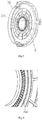
Fig. 1 is an exploded schematic diagram of an embodiment of a video camera provided by the present application; -
Fig. 2 is a schematic diagram of the video camera ofFig. 1 , with a base and a lens assembly assembled together; -
Fig. 3 is a schematic assembly diagram illustrating an of a base and a lens assembly of the video camera ofFig. 1 ; -
Fig. 4 is a schematic structural diagram of a rotating support frame of the video camera ofFig. 1 ; -
Fig. 5 is a schematic structural diagram of the base of the video camera ofFig. 1 ; -
Fig. 6 is a partially enlarged schematic diagram of a portion A inFig. 4 ; -
Fig. 7 is a schematic cross-sectional view of the video camera ofFig. 1 . - In order to make the objectives, technical solutions, and advantages of the present application more clear, the present application will be described in more detail with reference to the accompanying drawings and examples below. In the drawings, identical or similar reference numerals refer to identical or similar elements or functionally identical or similar elements. Obviously, the described embodiments are for only some embodiments of the present application, but not all the embodiments. Based on the embodiments in the present application, all other embodiments obtained by those skilled in the art without any creative efforts belong to the scope of protection of the present application.
- In the description of the present application, the orientations or positional relationships indicated by the terms "center", "longitudinal", "lateral", "front", "rear", "left", "right", "vertical", "horizontal", "top", "bottom", "inner", "outer" and the like are based on the those shown in the drawings and are merely for the convenience of describing the embodiments of the present application and simplifying the description, rather than indicating or implying that the referenced devices or elements must have a specific orientation, or be constructed and operated in a specific orientation, and therefore cannot be understood as a limitation to the protection scope of the embodiments of the present application.
- As shown in
Fig. 1 ,2 and7 , the video camera provided by the present embodiment includes alens assembly 1, anupper shell assembly 2 and alower shell assembly 3. - Wherein, the
lens assembly 1 can adjust its own "pan direction" (0-360 degrees) and "pitch direction" manually or electrically to set an angle range of a camera lens direction. "Pan direction" is a direction in which thelens assembly 1 rotates about a shaft 12 (as shown inFig. 7 ), i.e., the P-direction mentioned in the present application. - The
upper shell assembly 2 may include a cover, made of transparent material, covering thelens assembly 1. Theupper shell assembly 2 is fixedly connected to thelens assembly 1 by a fastener (such as ascrew 7, as shown inFig. 7 ), and thelens assembly 1 is provided on thelower shell assembly 3 so as to be rotatable in P-direction. Thus, theshell assembly 2 and thelens assembly 1 can rotate together in the P-direction relative to thelower shell assembly 3. - The
upper shell assembly 2 is provided with afirst protrusion 21, thelower shell assembly 3 is provided with asecond protrusion 31, and thefirst protrusion 21 and thesecond protrusion 31 are press-fitted to each other so as to limit the rotation of thelens assembly 1 relative to thelower shell assembly 3 in the P-direction. When thefirst protrusion 21 is detached from thesecond protrusion 31, thelens assembly 1 and theupper shell assembly 2 can rotate together in the P-direction relative to thelower shell assembly 3. - According to the present embodiment, for rotation adjustment of the
lens assembly 1 in P-direction, firstly thefirst protrusion 21 is moved away from thesecond protrusion 31 in the direction of theshaft 12, so as to detach thefirst protrusion 21 from thesecond protrusion 31. During the above process, theupper shell assembly 2 and thelens assembly 1 can still be connected together. Then, thelens assembly 1 and theupper shell assembly 2 are rotated in the P-direction to a target direction, i.e., theupper shell assembly 2 and thelens assembly 1 can rotate in the P-direction relative to thelower shell assembly 3. In this process, thefirst protrusion 21 is directly detached from thesecond protrusion 31, so that a rotation adjustment of thelens assembly 1 in P-direction can be realized without removing theupper shell assembly 2 from thelens assembly 1, which is convenient to operate. - In one embodiment, the
first protrusion 21 includes first teeth spaced apart in the circumferential direction of theupper shell assembly 2, and thesecond protrusion 31 includes second teeth spaced apart in the circumferential direction of thelower shell assembly 3, and these first and second teeth are press-fitted to each other through engagement. By detaching the first teeth from the second teeth, thelens assembly 1 and theupper shell assembly 2 can rotate together in the P-direction relative to thelower shell assembly 3. The locking and adjustment between thelens assembly 1 and thelower shell assembly 3 is realized by means of teeth engagement in the present embodiment, and the tooth structure is convenient to engage and disengage, easy to operate, and is highly reliable. Further, the process of manufacturing the teeth is relatively simple and the cost is low. - In one embodiment, there are at least two first teeth. An interval between adjacent two of said second teeth is set to be greater than the width of one of said first teeth and less than the sum of the widths of two of said first teeth, so as to accommodate one of said first teeth.
- In one embodiment, three of said first teeth are uniformly spaced circumferentially on the bottom of the
upper shell assembly 2, and said second teeth are disposed on an inner surface of a side wall of thelower shell assembly 3. This is suitable for the case where theupper shell assembly 2 is covered by the side wall of thelower shell assembly 3. Of course, said second teeth may also be disposed on other parts of thelower shell assembly 3 as long as said first teeth can be easily engaged with or detached from said second teeth. - As shown in
Fig. 1 , in one embodiment, thelower shell assembly 3 includes abase 32 and alower shell 33. The inner surface of thelower shell 33 is fixedly connected to the lower surface of thebase 32, and thesecond protrusion 31 is provided on the inner surface of the side wall of thelower shell 33, which is higher than a portion of thebase 32. Thelens assembly 1 is provided on the upper surface of the base 32 so as to be rotatable in the P-direction. Wherein, the surface away from thelens assembly 1 is referred to as "lower surface", and the surface closer to thelens assembly 1 is referred to as "upper surface". - As shown in
Figs. 3 to 7 , in one embodiment, the P-direction adjustment mechanism of said video camera further includes arotating support frame 4, which has a body, and a mountingportion 41 and anelastic arm 42 provided on the body. Wherein the mountingportion 41 is fixedly connected to the lower surface of thelens assembly 1, and theelastic arm 42 extends in P-direction to form a free end with aprojection 421. Optionally, the body of therotating support frame 4 has a ring shape, of which an inner ring is provided with the mountingportion 41 and an outer ring is provided with theelastic arm 42. Wherein, the mountingportion 41 is a lug with a through hole, a plurality of lugs are disposed at intervals along the inner ring of the body, and thus therotating support frame 4 can be fixedly connected to the lower surface of thelens assembly 1 by inserting the screw into the through hole in the lug. Therefore, when thelens assembly 1 is rotated in P-direction, therotating support frame 4 and thelens assembly 1 still remain fixedly connected in the P-direction and in a direction of the center line of theshaft 12. Theelastic arm 42 is similar to a cantilever arm, of which one end is fixed and the other end is a free end in a suspended state. In the present embodiment, threeelastic arms 42 are provided at intervals along the outer ring of the body. -
Circumferential teeth 321 are provided on the upper surface of thebase 32. Thecircumferential teeth 321 are frictionally engaged with theprojection 421 to limit the rotation of thelens assembly 1 in P-direction relative to thebase 32. Thus, when thefirst protrusion 21 and thesecond protrusion 31 are press-fitted to each other so as to limit the rotation of thelens assembly 1 in the P-direction relative to thelower shell assembly 3, thecircumferential teeth 321 and theprojection 421 are frictionally engaged, which would limit to some extent the rotation of thelens assembly 1 in P-direction relative to thelower shell assembly 3. It is able to effectively prevent saidlens assembly 1 from shaking due to that the interval between adjacent two of the second teeth is greater than the width of one of the first teeth. However, when thelens assembly 1 or theupper shell assembly 2 is driven by a P-direction force exerted thereon as soon as thefirst protrusion 21 is detached from thesecond protrusion 31, thecircumferential teeth 321 allow theprojection 421 to be detached from an gap between two adjacentcircumferential teeth 321, which enables thelens assembly 1 to rotate in the P-direction relative to thelower shell assembly 3. Theelastic arm 41 is subjected to a force from the base 32 when thelens assembly 1 is rotated in the P-direction, so that the frictional engagement, i.e., the damping, between theelastic arm 41 and thecircumferential teeth 321 can be felt by hand, which provides a good hand feeling. - As shown in
Figs. 1 and7 , in one embodiment, the P-direction adjustment mechanism of said video camera further includes anelastic sealing ring 5, which is disposed between thelens assembly 1 and thebase 32, and a pressing force in the direction of the center line of theshaft 12 is provided by therotating support frame 4 and thebase 32, so as to prevent water in the base 32 from entering thelens assembly 1 via thelens assembly 1 and thebase 32. Theelastic sealing ring 5 may be made of waterproof silica with elasticity, which exhibits fairly good sealing effect as the base 32 presses theelastic sealing ring 5 in the direction of the center line of theshaft 12. - As shown in
Figs. 3 and7 , in one embodiment, a base mounting portion 11 is provided on the lower surface of thelens assembly 1, and therotating support frame 4 is sleeved outside the base mounting portion 11. The P-direction adjustment mechanism of said video camera includes apressing plate 6, which is disposed on the lower surface of thebase 32 and fastened on the base mounting portion 11 by means of a screw, thebase 32 can be fixed relative to thelens assembly 1 in the direction of the center line of theshaft 12 by means of a screw, while the freedom degree of thelens assembly 1 relative to the base 32 in P-direction is retained. During assembly, theelastic sealing ring 5 is sleeved outside the base mounting portion 11, then compressed by therotating support frame 4, and finally compressed and fixed by thebase 32 for the second time. Both therotating support frame 4 and the base 32 provide a pressing force in the direction of the center line of theshaft 12. As thebase 32 is fixed on thelens assembly 1, three parts (i.e., theelastic sealing ring 5, therotating support frame 4 and the base 32) have a certain thickness, and the base mounting portion 11 protrudes from therotating support frame 4 to compensate for the thickness of these three parts, which further facilitates thepressing plate 6 to ultimately fix the entire structure by means of a screw. - In one embodiment, the
upper shell assembly 2 is provided with a plurality of threadedholes 22 in the direction of the center line of theshaft 12, and these threadedholes 22 are circumferentially spaced around theupper shell assembly 2. Accordingly, thelens assembly 1 is provided with a threadedhole structure 13. Therefore, thescrew 7 passes through the threaded hole structures of theupper shell assembly 2 and thelens assembly 1 in sequence, and thescrew 7 is tightened so that theupper shell assembly 2 and thelens assembly 1 are fixedly connected. - For rotation adjustment of the
lens assembly 1 in P-direction, firstly thescrew 7 is loosened to some extent without being detached from theupper shell assembly 2 and thelens assembly 1. In this way, theupper shell assembly 2 and thelens assembly 1 are still fixedly connected in the P-direction and in the direction of the center line of theshaft 12. After thescrew 7 is loosened, theupper shell assembly 2 moves away from thelens assembly 1 in the direction of the center line of theshaft 12, during which thelower shell assembly 3 and thelens assembly 1 are still fixedly connected in the direction of the center line of theshaft 12 while they have a freedom degree in the P-direction, thus after thefirst protrusion 21 is detached from thesecond protrusion 31 in the direction of the center line of theshaft 12, it is possible for thelens assembly 1 and theupper shell assembly 2 to rotate together in the P-direction relative to thelower shell assembly 3 without removing theupper shell assembly 2 from thelens assembly 1, which makes the P-direction adjustment easier and more convenient. - The foregoing embodiments are merely used to illustrate rather than to limit the technical solutions of the present application. It will be appreciated by those of ordinary skill in the art that modifications can be made to the technical solution recited in the foregoing embodiments, or equivalent substitutions can be made to some parts thereof. Any modifications, equivalent substitutions, and improvements and the like that are made within the spirit and principle of the present application shall be included in the protection scope of this application.
| 1 | | 2 | |
| 3 | | 4 | rotating |
| 5 | | 6 | pressing |
| 7 | screw | 11 | |
| 12 | | 13 | threaded hole structure |
| 21 | a | 22 | threaded hole |
| 31 | a | 32 | |
| 33 | | 321 | |
| 41 | | 42 | |
| 421 | projection |
Claims (9)
- A video camera, comprising a lens assembly (1), an upper shell assembly (2) and a lower shell assembly (3), the upper shell assembly (2) covering the lens assembly (1); wherein, the lens assembly (1) is fixedly connected to the upper shell assembly (2), and both the lens assembly (1) and the upper shell assembly (2) are provided on the lower shell assembly (3) so as to be rotatable in P-direction, and the upper shell assembly (2) is provided with a first protrusion (21), and the lower shell assembly (3) is provided with a second protrusion (31), and the first protrusion (21) and the second protrusion (31) are press-fitted to each other so as to limit the rotation of the lens assembly (1) in the P-direction relative to the lower shell assembly (3).
- The video camera according to claim 1, wherein, the first protrusion (21) comprises first teeth spaced apart in a circumferential direction of the upper shell assembly (2), and the second protrusion (31) comprises second teeth spaced apart in a circumferential direction of the lower shell assembly (3), and the first teeth and the second teeth are press-fitted to each other through engagement.
- The video camera according to claim 2, wherein, there are at least two first teeth, and an interval between adjacent two of the second teeth is set to be greater than a width of one of the first teeth and less than the sum of the widths of two of the first teeth.
- The video camera according to claim 3, further comprising a P-direction adjustment mechanism, wherein, three of the first teeth are uniformly spaced circumferentially on a bottom of the upper shell assembly (2), and the second teeth are disposed on an inner surface of a side wall of the lower shell assembly (3).
- The video camera according to any one of claims 1 to 4, wherein, the lower shell assembly (3) comprises a base (32) and a lower shell (33), and the lower shell (33) is fixedly connected to a lower surface of the base (32), and the second protrusion (31) is provided on an inner surface of a side wall of the lower shell (33), and the lens assembly (1) is provided on an upper surface of the base (32) so as to be rotatable in the P-direction.
- The video camera according to claim 5, wherein, circumferential teeth (321) are provided on the upper surface of the base (32);
the video camera further comprises a rotating support frame (4) that comprises a mounting portion (41) and an elastic arm (42); the mounting portion (41) is fixedly connected to a lower surface of the lens assembly (1); the elastic arm (42) extends in the P-direction to form a free end with a projection (421); the circumferential teeth (321) are frictionally engaged with the projection (421), and when the lens assembly (1) or the upper shell assembly (2) is driven by a P-direction force exerted thereon, the circumferential teeth (321) allow the projection (421) to be detached from an gap between two adjacent circumferential teeth (321), which enables the lens assembly (1) to rotate in the P-direction relative to the lower shell assembly (3). - The video camera according to claim 6, further comprising an elastic sealing ring (5) that is disposed between the lens assembly (1) and the base (32), and a pressing force in a direction of a center line of a shaft (12) is provided by the rotating support frame (4) and the base (32), so as to prevent water in the base (32) from entering the lens assembly (1) via the lens assembly (1) and the base (32).
- The video camera according to claim 7, wherein, a base mounting portion (11) is provided on the lower surface of the lens assembly (1), and the rotating support frame (4) is sleeved outside the base mounting portion (11) that protrudes from the rotating support frame (4);
the P-direction adjustment mechanism of the video camera further comprises a pressing plate (6), which is disposed on the lower surface of the base (32) and fastened on the base mounting portion (11) by means of a screw. - The video camera according to claim 1, wherein, the upper shell assembly (2) is a transparent cover, whose peripheral edge is fixedly connected to the lens assembly (1) by means of a screw.
Applications Claiming Priority (2)
| Application Number | Priority Date | Filing Date | Title |
|---|---|---|---|
| CN201721723216.6U CN207830867U (en) | 2017-12-12 | 2017-12-12 | A kind of video camera |
| PCT/CN2018/098476 WO2019114285A1 (en) | 2017-12-12 | 2018-08-03 | Video camera |
Publications (2)
| Publication Number | Publication Date |
|---|---|
| EP3726119A1 true EP3726119A1 (en) | 2020-10-21 |
| EP3726119A4 EP3726119A4 (en) | 2021-01-20 |
Family
ID=63387390
Family Applications (1)
| Application Number | Title | Priority Date | Filing Date |
|---|---|---|---|
| EP18889640.1A Pending EP3726119A4 (en) | 2017-12-12 | 2018-08-03 | Video camera |
Country Status (4)
| Country | Link |
|---|---|
| US (1) | US11418718B2 (en) |
| EP (1) | EP3726119A4 (en) |
| CN (1) | CN207830867U (en) |
| WO (1) | WO2019114285A1 (en) |
Families Citing this family (12)
| Publication number | Priority date | Publication date | Assignee | Title |
|---|---|---|---|---|
| CA188302S (en) * | 2019-01-07 | 2022-02-04 | Hangzhou Hikvision Digital Tec | Packaging box |
| USD943410S1 (en) * | 2019-01-18 | 2022-02-15 | Hangzhou Hikvision Digital Technology Co., Ltd. | Packaging box |
| USD933471S1 (en) * | 2019-03-12 | 2021-10-19 | Hangzhou Hikvision Digital Technology Co., Ltd. | Packaging box |
| US11519784B2 (en) * | 2020-05-25 | 2022-12-06 | Viettel Group | Thermal imaging radar |
| CN112863034A (en) * | 2020-12-31 | 2021-05-28 | 重庆数宜信信用管理有限公司 | Face recognition entrance guard that unit building used |
| CN113055564B (en) * | 2021-02-07 | 2023-07-25 | 杭州海康威视数字技术股份有限公司 | Hemispherical camera P-direction adjusting structure |
| CN113315893B (en) * | 2021-05-17 | 2023-10-27 | 杭州海康威视数字技术股份有限公司 | Video camera and video apparatus |
| CN114658995B (en) * | 2022-03-25 | 2023-09-29 | 杭州海康威视数字技术股份有限公司 | Shell of camera and conch camera |
| CN115002324B (en) * | 2022-05-27 | 2024-03-26 | 杭州海康威视数字技术股份有限公司 | Video camera |
| CN115022506A (en) * | 2022-05-27 | 2022-09-06 | 杭州海康威视数字技术股份有限公司 | Video camera |
| CN115022522B (en) * | 2022-07-12 | 2023-08-29 | 杭州海康威视数字技术股份有限公司 | Multi-view camera |
| CN116528034B (en) * | 2023-06-26 | 2023-09-19 | 杭州海康威视数字技术股份有限公司 | Video camera for elevator scene |
Family Cites Families (18)
| Publication number | Priority date | Publication date | Assignee | Title |
|---|---|---|---|---|
| US5240220A (en) * | 1990-09-12 | 1993-08-31 | Elbex Video Ltd. | TV camera supporting device |
| US6234691B1 (en) * | 1998-06-15 | 2001-05-22 | Philips Electronics North America Corporation | Apparatus for mounting a surveillance camera |
| CA2300605A1 (en) * | 2000-03-14 | 2001-09-14 | Silent Witness Enterprises Ltd. | Infrared illuminator housing and assembly |
| US7387453B2 (en) * | 2005-09-02 | 2008-06-17 | Pelco, Inc. | Camera support and mounting assembly |
| JP4771827B2 (en) * | 2006-02-21 | 2011-09-14 | 三洋電機株式会社 | Surveillance camera |
| CN201215984Y (en) * | 2008-03-12 | 2009-04-01 | 上海豪宙网络通讯设备有限公司 | Omnidirectional network camera device |
| KR100950733B1 (en) * | 2008-05-08 | 2010-04-01 | (주)씨프로 | A supporting devices for camera module |
| WO2010029727A1 (en) * | 2008-09-09 | 2010-03-18 | パナソニック株式会社 | Dome camera |
| JP5113785B2 (en) * | 2009-02-27 | 2013-01-09 | パナソニック株式会社 | Dome camera |
| CN101917545B (en) * | 2010-07-23 | 2012-03-14 | 北京宝塔山科技有限公司 | All-around intelligent electric control camera |
| JP2012032636A (en) * | 2010-07-30 | 2012-02-16 | Nidec Copal Corp | Pan and tilt device |
| WO2013121880A1 (en) * | 2012-02-14 | 2013-08-22 | 富士フイルム株式会社 | Dome-shaped camera |
| EP2657762B1 (en) * | 2012-04-25 | 2014-03-26 | Axis AB | Top cover assembly for a monitoring camera |
| JP6064458B2 (en) * | 2012-09-05 | 2017-01-25 | ソニー株式会社 | Imaging device |
| CN204741501U (en) * | 2015-05-27 | 2015-11-04 | 深圳市全景达科技有限公司 | 360 degree pancam shell |
| US9952485B1 (en) * | 2015-06-10 | 2018-04-24 | Innotech Security, Inc. | Video surveillance camera having a separable and removable gimbal |
| US10196007B2 (en) * | 2016-11-16 | 2019-02-05 | GM Global Technology Operations LLC | Vehicle sensor mounting systems |
| US10341570B1 (en) * | 2018-04-10 | 2019-07-02 | Ademco Inc. | Assembly and method for restricting indefinite one-way rotation of a rotatable camera |
-
2017
- 2017-12-12 CN CN201721723216.6U patent/CN207830867U/en active Active
-
2018
- 2018-08-03 WO PCT/CN2018/098476 patent/WO2019114285A1/en unknown
- 2018-08-03 US US16/769,961 patent/US11418718B2/en active Active
- 2018-08-03 EP EP18889640.1A patent/EP3726119A4/en active Pending
Also Published As
| Publication number | Publication date |
|---|---|
| WO2019114285A1 (en) | 2019-06-20 |
| EP3726119A4 (en) | 2021-01-20 |
| CN207830867U (en) | 2018-09-07 |
| US11418718B2 (en) | 2022-08-16 |
| US20200389597A1 (en) | 2020-12-10 |
Similar Documents
| Publication | Publication Date | Title |
|---|---|---|
| EP3726119A1 (en) | Video camera | |
| US9497362B2 (en) | Imaging device and plate spring | |
| CN100574374C (en) | The surveillance camera gimbal device | |
| EP3557859B1 (en) | Multi-lens camera | |
| US11272123B2 (en) | Multi-lens camera | |
| US8506181B2 (en) | Imaging device and plate spring | |
| CA3094560A1 (en) | Multi-view camera and lens adjustment device | |
| US8783974B2 (en) | Photographic apparatus and case structure thereof | |
| EP3712740A1 (en) | Protective case for mobile phone and tablet computer | |
| CN109451227A (en) | A kind of video camera | |
| JP4438398B2 (en) | Optical axis rotation structure of surveillance camera device | |
| EP3706188A1 (en) | Handheld infrared photogrammetric apparatus | |
| CN210839746U (en) | Security protection camera with angle modulation function | |
| CN216467627U (en) | Truck camera mounting structure | |
| WO2022166498A1 (en) | P-direction adjusting structure and dome camera | |
| JP3748544B2 (en) | TV camera device for surveillance | |
| CN209089087U (en) | One kind being used for camera protection device | |
| KR100383735B1 (en) | Apparatus framing of monitoring Camera | |
| CN210466476U (en) | License plate recognition equipment | |
| JP2604775Y2 (en) | TV camera with rotating mechanism | |
| CN220896764U (en) | Camera head | |
| CN204785451U (en) | It is rotatory from rapping bar | |
| CN214675375U (en) | Monitor | |
| CN217875199U (en) | Rotation regulation supporting structure and surveillance camera head | |
| WO2022257393A1 (en) | Multidirectional adjustment support and camera device |
Legal Events
| Date | Code | Title | Description |
|---|---|---|---|
| STAA | Information on the status of an ep patent application or granted ep patent |
Free format text: STATUS: THE INTERNATIONAL PUBLICATION HAS BEEN MADE |
|
| PUAI | Public reference made under article 153(3) epc to a published international application that has entered the european phase |
Free format text: ORIGINAL CODE: 0009012 |
|
| STAA | Information on the status of an ep patent application or granted ep patent |
Free format text: STATUS: REQUEST FOR EXAMINATION WAS MADE |
|
| 17P | Request for examination filed |
Effective date: 20200529 |
|
| AK | Designated contracting states |
Kind code of ref document: A1 Designated state(s): AL AT BE BG CH CY CZ DE DK EE ES FI FR GB GR HR HU IE IS IT LI LT LU LV MC MK MT NL NO PL PT RO RS SE SI SK SM TR |
|
| AX | Request for extension of the european patent |
Extension state: BA ME |
|
| A4 | Supplementary search report drawn up and despatched |
Effective date: 20201217 |
|
| RIC1 | Information provided on ipc code assigned before grant |
Ipc: F16M 11/20 20060101ALI20201211BHEP Ipc: H04N 5/225 20060101ALI20201211BHEP Ipc: F16M 11/10 20060101ALI20201211BHEP Ipc: F16M 13/02 20060101ALI20201211BHEP Ipc: F16M 11/18 20060101ALI20201211BHEP Ipc: F16M 11/04 20060101AFI20201211BHEP Ipc: G02B 7/00 20060101ALI20201211BHEP Ipc: G08B 13/196 20060101ALI20201211BHEP |
|
| DAV | Request for validation of the european patent (deleted) | ||
| DAX | Request for extension of the european patent (deleted) | ||
| STAA | Information on the status of an ep patent application or granted ep patent |
Free format text: STATUS: EXAMINATION IS IN PROGRESS |
|
| 17Q | First examination report despatched |
Effective date: 20230403 |