EP4239444B1 - Verschiebbare elektronische vorrichtung - Google Patents
Verschiebbare elektronische vorrichtung Download PDFInfo
- Publication number
- EP4239444B1 EP4239444B1 EP21901109.5A EP21901109A EP4239444B1 EP 4239444 B1 EP4239444 B1 EP 4239444B1 EP 21901109 A EP21901109 A EP 21901109A EP 4239444 B1 EP4239444 B1 EP 4239444B1
- Authority
- EP
- European Patent Office
- Prior art keywords
- housing
- electronic device
- end portion
- connecting member
- sliding
- Prior art date
- Legal status (The legal status is an assumption and is not a legal conclusion. Google has not performed a legal analysis and makes no representation as to the accuracy of the status listed.)
- Active
Links
Images


Classifications
-
- G—PHYSICS
- G09—EDUCATION; CRYPTOGRAPHY; DISPLAY; ADVERTISING; SEALS
- G09F—DISPLAYING; ADVERTISING; SIGNS; LABELS OR NAME-PLATES; SEALS
- G09F9/00—Indicating arrangements for variable information in which the information is built-up on a support by selection or combination of individual elements
- G09F9/30—Indicating arrangements for variable information in which the information is built-up on a support by selection or combination of individual elements in which the desired character or characters are formed by combining individual elements
- G09F9/301—Indicating arrangements for variable information in which the information is built-up on a support by selection or combination of individual elements in which the desired character or characters are formed by combining individual elements flexible foldable or roll-able electronic displays, e.g. thin LCD, OLED
-
- G—PHYSICS
- G06—COMPUTING OR CALCULATING; COUNTING
- G06F—ELECTRIC DIGITAL DATA PROCESSING
- G06F1/00—Details not covered by groups G06F3/00 - G06F13/00 and G06F21/00
- G06F1/16—Constructional details or arrangements
- G06F1/1613—Constructional details or arrangements for portable computers
- G06F1/1615—Constructional details or arrangements for portable computers with several enclosures having relative motions, each enclosure supporting at least one I/O or computing function
- G06F1/1624—Constructional details or arrangements for portable computers with several enclosures having relative motions, each enclosure supporting at least one I/O or computing function with sliding enclosures, e.g. sliding keyboard or display
-
- G—PHYSICS
- G06—COMPUTING OR CALCULATING; COUNTING
- G06F—ELECTRIC DIGITAL DATA PROCESSING
- G06F1/00—Details not covered by groups G06F3/00 - G06F13/00 and G06F21/00
- G06F1/16—Constructional details or arrangements
- G06F1/1613—Constructional details or arrangements for portable computers
- G06F1/1633—Constructional details or arrangements of portable computers not specific to the type of enclosures covered by groups G06F1/1615 - G06F1/1626
- G06F1/1637—Details related to the display arrangement, including those related to the mounting of the display in the housing
- G06F1/1652—Details related to the display arrangement, including those related to the mounting of the display in the housing the display being flexible, e.g. mimicking a sheet of paper, or rollable
-
- G—PHYSICS
- G06—COMPUTING OR CALCULATING; COUNTING
- G06F—ELECTRIC DIGITAL DATA PROCESSING
- G06F1/00—Details not covered by groups G06F3/00 - G06F13/00 and G06F21/00
- G06F1/16—Constructional details or arrangements
- G06F1/1613—Constructional details or arrangements for portable computers
- G06F1/1633—Constructional details or arrangements of portable computers not specific to the type of enclosures covered by groups G06F1/1615 - G06F1/1626
- G06F1/1675—Miscellaneous details related to the relative movement between the different enclosures or enclosure parts
- G06F1/1679—Miscellaneous details related to the relative movement between the different enclosures or enclosure parts for locking or maintaining the movable parts of the enclosure in a fixed position, e.g. latching mechanism at the edge of the display in a laptop or for the screen protective cover of a PDA
-
- H—ELECTRICITY
- H04—ELECTRIC COMMUNICATION TECHNIQUE
- H04M—TELEPHONIC COMMUNICATION
- H04M1/00—Substation equipment, e.g. for use by subscribers
- H04M1/02—Constructional features of telephone sets
- H04M1/0202—Portable telephone sets, e.g. cordless phones, mobile phones or bar type handsets
- H04M1/0206—Portable telephones comprising a plurality of mechanically joined movable body parts, e.g. hinged housings
- H04M1/0208—Portable telephones comprising a plurality of mechanically joined movable body parts, e.g. hinged housings characterized by the relative motions of the body parts
- H04M1/0235—Slidable or telescopic telephones, i.e. with a relative translation movement of the body parts; Telephones using a combination of translation and other relative motions of the body parts
- H04M1/0237—Sliding mechanism with one degree of freedom
-
- H—ELECTRICITY
- H04—ELECTRIC COMMUNICATION TECHNIQUE
- H04M—TELEPHONIC COMMUNICATION
- H04M1/00—Substation equipment, e.g. for use by subscribers
- H04M1/02—Constructional features of telephone sets
- H04M1/0202—Portable telephone sets, e.g. cordless phones, mobile phones or bar type handsets
- H04M1/026—Details of the structure or mounting of specific components
- H04M1/0266—Details of the structure or mounting of specific components for a display module assembly
- H04M1/0268—Details of the structure or mounting of specific components for a display module assembly including a flexible display panel
-
- G—PHYSICS
- G06—COMPUTING OR CALCULATING; COUNTING
- G06F—ELECTRIC DIGITAL DATA PROCESSING
- G06F1/00—Details not covered by groups G06F3/00 - G06F13/00 and G06F21/00
- G06F1/16—Constructional details or arrangements
- G06F1/1613—Constructional details or arrangements for portable computers
- G06F1/1633—Constructional details or arrangements of portable computers not specific to the type of enclosures covered by groups G06F1/1615 - G06F1/1626
- G06F1/1675—Miscellaneous details related to the relative movement between the different enclosures or enclosure parts
- G06F1/1681—Details related solely to hinges
Definitions
- Various embodiments disclosed in this document relate to an electronic device, and more particularly, to a slideable electronic device having a side protruding and retracting structure.
- a large-area display is advantageous for utilization of digital contents, but it may be advantageous for the electronic device to have a small form-factor for ease of portability and use.
- flexible displays using technology such as organic light-emitting diodes (OLED), rollable or slideable electronic devices that mount flexible displays so as to mount large-area displays in small form-factors may be utilized.
- OLED organic light-emitting diodes
- a double housing structure in which a protruding and retracting portion of a flexible display panel is protected by an inner housing and in which the inner housing is protruded from and retracting into an outer housing may be utilized.
- the conventional double housing structure because a display between the outer housing and the inner housing should receive the inner housing, it may be difficult to reduce a thickness of the bezel.
- a slideable electronic device may have a structure in which a flexible display panel is protruded from and retracted into a main body.
- a side surface of the flexible display panel may be exposed. Accordingly, the exposed side surface of the flexible display panel may be damaged due to an external impact, or a foreign material may be introduced into the slideable electronic device through an exposed portion.
- a slideable electronic device in which a side surface of a flexible display panel is protected and in which a thickness of a bezel is reduced and in which a sense of unity in appearance is maintained may be provided.
- a slideable electronic device in which a transmission and reception performance is improved by exposing a wireless transceiver may be provided.
- an electronic device may include a first housing; a second housing slidably coupled to the first housing; a flexible display panel retracted into and drawn out from the electronic device by a sliding motion between the first housing and the second housing; a protruding and retracting member protruded to a space between lateral portions of the first housing and the second housing generated at a side surface of the flexible display panel when the flexible display panel is drawn out and retracted into the electronic device from the space when the flexible display panel is retracted; an interlocking structure coupled to at least one of the first housing or the second housing and configured to convert the sliding motion into a lateral movement; a connecting member having flexibility configured such that one end thereof is coupled to one end of the protruding and retracting member and the other end thereof is connected to the interlocking structure to be movable along the lateral movement; and a guide positioned in at least one of the first housing or the second housing and configured to convert the lateral movement of the connecting member generated by an action of the interlocking
- the interlocking structure may include a sliding rail disposed on an inner side surface of at least one of the first housing or the second housing; a sliding block having one end portion slidably coupled to the sliding rail; and at least one link bar having one end portion rotatably coupled to the other end portion of the sliding block and the other end portion rotatably connected to the connecting member.
- the sliding rail may include a groove formed on an inner side surface of the first housing, and the guide may be fixedly disposed at the second housing in a lateral portion exposed to the outside during the withdrawing operation of the second housing.
- the sliding rail may include a groove formed on an inner side surface of the second housing, and the guide may be fixedly disposed at the first housing at a lateral portion exposed to the outside during the withdrawing operation of the first housing.
- the sliding rail may include a first sliding rail including a first groove formed on an inner side surface of the first housing and a second sliding rail including a second groove formed on an inner side surface of the second housing
- the sliding block may include a first sliding block slidably coupled to the first sliding rail and a second sliding block slidably coupled to the second sliding rail
- the link bar may include a first link bar having one end portion rotatably coupled to the other end portion of the first sliding block and the other end portion rotatably connected to the other end portion of the connecting member and a second link bar having one end portion rotatably coupled to the other end portion of the second sliding block and the other end portion rotatably connected to the other end portion of the connecting member, wherein the first link bar and the second link may be disposed to face each other based on a center line of the connecting member.
- the electronic device may further include a foreign material blocking member in contact with a lower part of the connecting member, slidably coupled on an inner surface of the first housing or the second housing, and configured to block a gap existing between a lower part of the connecting member and an inner surface of the first housing or the second housing to prevent a foreign material from being introduced into the electronic device.
- a foreign material blocking member in contact with a lower part of the connecting member, slidably coupled on an inner surface of the first housing or the second housing, and configured to block a gap existing between a lower part of the connecting member and an inner surface of the first housing or the second housing to prevent a foreign material from being introduced into the electronic device.
- the sliding rail may include a sliding limiting member disposed close to an end portion in a direction in which the flexible display panel is retracted on a surface thereof and configured to apply a resistance force to a sliding movement therebetween with respect to the sliding block, wherein the sliding limiting member may have an asymmetrical resistance force that provides a low resistance force to a sliding movement of the sliding block when an operation of withdrawing the flexible display panel is performed and that provides a high resistance force to the sliding movement of the sliding block in an operation of retracting the flexible display panel.
- the connecting member may include a multi-bar structure including a plurality of bars disposed in parallel with each other and rotatably connected to each other.
- the connecting member may have one side disposed parallel to the bar and the other side disposed at a specific angle with the one side on a plane, and the other side may have a flat connecting member rotatably connected to the other end portion of the link bar.
- the sliding block may include a groove formed in the other end portion so that the one end portion of the link bar may be rotatably fitted, and the flat connecting member may include a groove formed to be rotatably fitted with the other end portion of the link bar at a distal end portion of the other side.
- the connecting member may include a plurality of guide blocks formed at one side of each of the plurality of bars, and the guide may include a guide rail slidably coupled to the plurality of guide blocks.
- the guide block may have a T-shaped cross-section, and the guide rail may have a cross-sectional shape corresponding to a cross-sectional shape of the guide block.
- the protruding and retracting member may be a side wall configured to protect the side surface of the flexible display panel.
- the protruding and retracting member may include or be connected to a wireless transceiver, and the wireless transceiver included in or connected to the protruding and retracting member by a sliding motion may change a position thereof inside the electronic device or be exposed to a space between the first housing and the second housing to improve a wireless reception performance.
- a slideable electronic device in which a protruding and retracting member is interlocked with a sliding motion to be protruded from and withdrawn to a side surface of a flexible display panel and in which the side surface of the flexible display panel is thus protected by the protruding and retracting member and that has a constant and thin bezel thickness.
- the protruding and retracting member protruding and retracting in interlocking with a sliding operation includes a wireless transceiver
- a slideable electronic device having an improved radio wave transmission and reception performance can be provided as the protruding and retracting in interlocking with a sliding operation includes a wireless transceiver.
- an electronic device capable of minimizing exposure can be provided.
- Fig. 1 is a block diagram illustrating an electronic device 101 in a network environment 100 according to various embodiments.
- the electronic device 101 in the network environment 100 may communicate with an electronic device 102 via a first network 198 (e.g., a short-range wireless communication network), or at least one of an electronic device 104 or a server 108 via a second network 199 (e.g., a long-range wireless communication network).
- the electronic device 101 may communicate with the electronic device 104 via the server 108.
- the electronic device 101 may include a processor 120, memory 130, an input module 150, a sound output module 155, a display module 160, an audio module 170, a sensor module 176, an interface 177, a connecting terminal 178, a haptic module 179, a camera module 180, a power management module 188, a battery 189, a communication module 190, a subscriber identification module(SIM) 196, or an antenna module 197.
- at least one of the components e.g., the connecting terminal 178) may be omitted from the electronic device 101, or one or more other components may be added in the electronic device 101.
- some of the components e.g., the sensor module 176, the camera module 180, or the antenna module 197) may be implemented as a single component (e.g., the display module 160).
- the processor 120 may execute, for example, software (e.g., a program 140) to control at least one other component (e.g., a hardware or software component) of the electronic device 101 coupled with the processor 120, and may perform various data processing or computation. According to one embodiment, as at least part of the data processing or computation, the processor 120 may store a command or data received from another component (e.g., the sensor module 176 or the communication module 190) in volatile memory 132, process the command or the data stored in the volatile memory 132, and store resulting data in non-volatile memory 134.
- software e.g., a program 140
- the processor 120 may store a command or data received from another component (e.g., the sensor module 176 or the communication module 190) in volatile memory 132, process the command or the data stored in the volatile memory 132, and store resulting data in non-volatile memory 134.
- the processor 120 may include a main processor 121 (e.g., a central processing unit (CPU) or an application processor (AP)), or an auxiliary processor 123 (e.g., a graphics processing unit (GPU), a neural processing unit (NPU), an image signal processor (ISP), a sensor hub processor, or a communication processor (CP)) that is operable independently from, or in conjunction with, the main processor 121.
- a main processor 121 e.g., a central processing unit (CPU) or an application processor (AP)
- auxiliary processor 123 e.g., a graphics processing unit (GPU), a neural processing unit (NPU), an image signal processor (ISP), a sensor hub processor, or a communication processor (CP)
- the main processor 121 may be adapted to consume less power than the main processor 121, or to be specific to a specified function.
- the auxiliary processor 123 may be implemented as separate from, or as part of the main processor 121.
- the auxiliary processor 123 may control at least some of functions or states related to at least one component (e.g., the display module 160, the sensor module 176, or the communication module 190) among the components of the electronic device 101, instead of the main processor 121 while the main processor 121 is in an inactive (e.g., sleep) state, or together with the main processor 121 while the main processor 121 is in an active state (e.g., executing an application).
- the auxiliary processor 123 e.g., an image signal processor or a communication processor
- the auxiliary processor 123 may include a hardware structure specified for artificial intelligence model processing.
- An artificial intelligence model may be generated by machine learning. Such learning may be performed, e.g., by the electronic device 101 where the artificial intelligence is performed or via a separate server (e.g., the server 108). Learning algorithms may include, but are not limited to, e.g., supervised learning, unsupervised learning, semi-supervised learning, or reinforcement learning.
- the artificial intelligence model may include a plurality of artificial neural network layers.
- the artificial neural network may be a deep neural network (DNN), a convolutional neural network (CNN), a recurrent neural network (RNN), a restricted boltzmann machine (RBM), a deep belief network (DBN), a bidirectional recurrent deep neural network (BRDNN), deep Q-network or a combination of two or more thereof but is not limited thereto.
- the artificial intelligence model may, additionally or alternatively, include a software structure other than the hardware structure.
- the memory 130 may store various data used by at least one component (e.g., the processor 120 or the sensor module 176) of the electronic device 101.
- the various data may include, for example, software (e.g., the program 140) and input data or output data for a command related thererto.
- the memory 130 may include the volatile memory 132 or the non-volatile memory 134.
- the program 140 may be stored in the memory 130 as software, and may include, for example, an operating system (OS) 142, middleware 144, or an application 146.
- OS operating system
- middleware middleware
- application application
- the input module 150 may receive a command or data to be used by another component (e.g., the processor 120) of the electronic device 101, from the outside (e.g., a user) of the electronic device 101.
- the input module 150 may include, for example, a microphone, a mouse, a keyboard, a key (e.g., a button), or a digital pen (e.g., a stylus pen).
- the sound output module 155 may output sound signals to the outside of the electronic device 101.
- the sound output module 155 may include, for example, a speaker or a receiver.
- the speaker may be used for general purposes, such as playing multimedia or playing record.
- the receiver may be used for receiving incoming calls. According to an embodiment, the receiver may be implemented as separate from, or as part of the speaker.
- the display module 160 may visually provide information to the outside (e.g., a user) of the electronic device 101.
- the display module 160 may include, for example, a display, a hologram device, or a projector and control circuitry to control a corresponding one of the display, hologram device, and projector.
- the display module 160 may include a touch sensor adapted to detect a touch, or a pressure sensor adapted to measure the intensity of force incurred by the touch.
- the audio module 170 may convert a sound into an electrical signal and vice versa. According to an embodiment, the audio module 170 may obtain the sound via the input module 150, or output the sound via the sound output module 155 or a headphone of an external electronic device (e.g., an electronic device 102) directly (e.g., wiredly) or wirelessly coupled with the electronic device 101.
- an external electronic device e.g., an electronic device 102
- directly e.g., wiredly
- wirelessly e.g., wirelessly
- the sensor module 176 may detect an operational state (e.g., power or temperature) of the electronic device 101 or an environmental state (e.g., a state of a user) external to the electronic device 101, and then generate an electrical signal or data value corresponding to the detected state.
- the sensor module 176 may include, for example, a gesture sensor, a gyro sensor, an atmospheric pressure sensor, a magnetic sensor, an acceleration sensor, a grip sensor, a proximity sensor, a color sensor, an infrared (IR) sensor, a biometric sensor, a temperature sensor, a humidity sensor, or an illuminance sensor.
- the interface 177 may support one or more specified protocols to be used for the electronic device 101 to be coupled with the external electronic device (e.g., the electronic device 102) directly (e.g., wiredly) or wirelessly.
- the interface 177 may include, for example, a high definition multimedia interface (HDMI), a universal serial bus (USB) interface, a secure digital (SD) card interface, or an audio interface.
- HDMI high definition multimedia interface
- USB universal serial bus
- SD secure digital
- a connecting terminal 178 may include a connector via which the electronic device 101 may be physically connected with the external electronic device (e.g., the electronic device 102).
- the connecting terminal 178 may include, for example, a HDMI connector, a USB connector, a SD card connector, or an audio connector (e.g., a headphone connector).
- the haptic module 179 may convert an electrical signal into a mechanical stimulus (e.g., a vibration or a movement) or electrical stimulus which may be recognized by a user via his tactile sensation or kinesthetic sensation.
- the haptic module 179 may include, for example, a motor, a piezoelectric element, or an electric stimulator.
- the camera module 180 may capture a still image or moving images.
- the camera module 180 may include one or more lenses, image sensors, image signal processors, or flashes.
- the power management module 188 may manage power supplied to the electronic device 101.
- the power management module 188 may be implemented as at least part of, for example, a power management integrated circuit (PMIC).
- PMIC power management integrated circuit
- the battery 189 may supply power to at least one component of the electronic device 101.
- the battery 189 may include, for example, a primary cell which is not rechargeable, a secondary cell which is rechargeable, or a fuel cell.
- the communication module 190 may support establishing a direct (e.g., wired) communication channel or a wireless communication channel between the electronic device 101 and the external electronic device (e.g., the electronic device 102, the electronic device 104, or the server 108) and performing communication via the established communication channel.
- the communication module 190 may include one or more communication processors that are operable independently from the processor 120 (e.g., the application processor (AP)) and supports a direct (e.g., wired) communication or a wireless communication.
- AP application processor
- the communication module 190 may include a wireless communication module 192 (e.g., a cellular communication module, a short-range wireless communication module, or a global navigation satellite system (GNSS) communication module) or a wired communication module 194 (e.g., a local area network (LAN) communication module or a power line communication (PLC) module).
- a wireless communication module 192 e.g., a cellular communication module, a short-range wireless communication module, or a global navigation satellite system (GNSS) communication module
- GNSS global navigation satellite system
- wired communication module 194 e.g., a local area network (LAN) communication module or a power line communication (PLC) module.
- LAN local area network
- PLC power line communication
- a corresponding one of these communication modules may communicate with the external electronic device via the first network 198 (e.g., a short-range communication network, such as BluetoothTM, wireless-fidelity (Wi-Fi) direct, or infrared data association (IrDA)) or the second network 199 (e.g., a long-range communication network, such as a legacy cellular network, a 5G network, a next-generation communication network, the Internet, or a computer network (e.g., LAN or wide area network (WAN)).
- first network 198 e.g., a short-range communication network, such as BluetoothTM, wireless-fidelity (Wi-Fi) direct, or infrared data association (IrDA)
- the second network 199 e.g., a long-range communication network, such as a legacy cellular network, a 5G network, a next-generation communication network, the Internet, or a computer network (e.g., LAN or wide area network (WAN)).
- the wireless communication module 192 may identify and authenticate the electronic device 101 in a communication network, such as the first network 198 or the second network 199, using subscriber information (e.g., international mobile subscriber identity (IMSI)) stored in the subscriber identification module 196.
- subscriber information e.g., international mobile subscriber identity (IMSI)
- the antenna module 197 may transmit or receive a signal or power to or from the outside (e.g., the external electronic device) of the electronic device 101.
- the antenna module 197 may include an antenna including a radiating element composed of a conductive material or a conductive pattern formed in or on a substrate (e.g., a printed circuit board (PCB)).
- the antenna module 197 may include a plurality of antennas (e.g., array antennas). In such a case, at least one antenna appropriate for a communication scheme used in the communication network, such as the first network 198 or the second network 199, may be selected, for example, by the communication module 190 (e.g., the wireless communication module 192) from the plurality of antennas.
- the signal or the power may then be transmitted or received between the communication module 190 and the external electronic device via the selected at least one antenna.
- another component e.g., a radio frequency integrated circuit (RFIC)
- RFIC radio frequency integrated circuit
- At least some of the above-described components may be coupled mutually and communicate signals (e.g., commands or data) therebetween via an inter-peripheral communication scheme (e.g., a bus, general purpose input and output (GPIO), serial peripheral interface (SPI), or mobile industry processor interface (MIPI)).
- an inter-peripheral communication scheme e.g., a bus, general purpose input and output (GPIO), serial peripheral interface (SPI), or mobile industry processor interface (MIPI)
- commands or data may be transmitted or received between the electronic device 101 and the external electronic device 104 via the server 108 coupled with the second network 199.
- Each of the electronic devices 102 or 104 may be a device of a same type as, or a different type, from the electronic device 101.
- all or some of operations to be executed at the electronic device 101 may be executed at one or more of the external electronic devices 102, 104, or 108. For example, if the electronic device 101 should perform a function or a service automatically, or in response to a request from a user or another device, the electronic device 101, instead of, or in addition to, executing the function or the service, may request the one or more external electronic devices to perform at least part of the function or the service.
- the one or more external electronic devices receiving the request may perform the at least part of the function or the service requested, or an additional function or an additional service related to the request, and transfer an outcome of the performing to the electronic device 101.
- the electronic device 101 may provide the outcome, with or without further processing of the outcome, as at least part of a reply to the request.
- a cloud computing, distributed computing, mobile edge computing (MEC), or client-server computing technology may be used, for example.
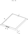
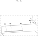
- FIG. 2A is a perspective view illustrating a front surface of an electronic device 101 in a state in which a flexible display panel 161 of the electronic device 101 is retracted according to embodiments of the disclosure.
- FIG. 2B is a perspective view illustrating a front surface of the electronic device 101 in a state in which the flexible display panel 161 of the electronic device 101 is drawn out according to embodiments of the disclosure.
- FIG. 2C is a perspective view illustrating a rear surface of the electronic device 101 in a state in which the flexible display panel 161 of the electronic device 101 is drawn out according to embodiments of the disclosure.
- FIG. 2D is a cross-sectional view illustrating the inside of the electronic device 101 in a state in which the flexible display panel 161 of the electronic device 101 is retracted according to embodiments of the disclosure.
- x, y, and z coordinate axes are represented, and the term “horizontal” in this specification may refer to a plane parallel to the x and y axes and/or a direction parallel to the plane, the term “vertical” may refer to a direction parallel to the z-axis, and the term “side surface” may refer to a plane perpendicular to the y-axis.
- an electronic device 101 may include a first housing 31, a second housing 32, a flexible display panel 161, a protruding and retracting member 33, and a connecting member 35.
- the first housing 31 and the second housing 32 may provide a space for mounting internal components of the electronic device 101, and protect the internal components from an external impact.
- the first housing 31 and the second housing 32 are slidably coupled to each other, for example, in the x-axis direction on the drawing.
- the first housing and the second housing may include sidewalls having a constant thickness in order to protect a lateral portion of the flexible display panel 161 to be described later, and a thickness T of the sidewalls may be defined as a bezel thickness.
- the flexible display panel 161 may perform an operation of being drawn out from or retracted to the inside of the first housing by a sliding motion between the first housing and the second housing.
- the flexible display panel 161 may be an organic light emitting diode (OLED) display panel.
- the flexible display panel 161 may include a cover for protecting a thin-film transistor (TFT) and display element on a surface of the panel, and the cover may include a synthetic resin material such as colorless polyimide or a transparent material having flexibility such as ultra thin glass.
- the flexible display panel 161 may include a flexible support member 1611 that may be curved while being retracted to the first housing and for structural support at a curved portion.
- the flexible support member 1611 may include a multi-joint structure in which a plurality of support plates are rotatably connected.
- the protruding and retracting member 33 may be positioned inside the electronic device 101 in a state in which the flexible display panel 161 is retracted and be protruded to a space existing between side surfaces of the first housing 31 and the second housing 32 when the flexible display panel 161 is drawn out. Further, when the flexible display panel 161 is retracted, the flexible display panel 161 may be retracted into the electronic device 101.
- a length of the protruding and retracting member 33 in the x-axis direction may be smaller than that of a gap formed between the first housing 31 and the second housing 32 in a state in which the flexible display panel 161 is drawn out.
- a mechanism in which the protruding and retracting member 33 is protruded and retracted will be described later.
- the protruding and retracting member 33 may be a side wall protecting a portion of the side surface of the flexible display panel 161 exposed to a space existing between side surfaces of the first housing 31 and the second housing 31 in a state in which the flexible display panel 161 is drawn out.
- the protruding and retracting member 33 may have substantially the same thickness T' as that of bezels of the first housing 31 and the second housing 32 in a state protruded to the side surface of the flexible display panel 161.
- T' that of bezels of the first housing 31 and the second housing 32 in a state protruded to the side surface of the flexible display panel 161.
- the protruding and retracting member 33 may include a wireless transceiver 331.
- the wireless transceiver may be a device for inputting and outputting radio waves, infrared rays, or signals for communication similar thereto.
- the wireless transceiver 331 may include an antenna module 197. Because the protruding and retracting member 33 includes the wireless transceiver 331, the wireless transceiver 331 may be exposed to the outside, as needed, and a wireless transmission and reception performance of the electronic device 101 may be improved.
- the protruding and retracting member 33 may include only a portion of the wireless transceiver 331 or may be connected to the wireless transceiver 331.
- a position of the wireless transceiver 331 may be changed inside the electronic device 101.
- the wireless transceiver 331 changes a position thereof to correspond to the change in radio wave transmission and reception characteristics of the electronic device 101 changing according to withdrawal or retraction of the flexible display panel 161, a wireless transmission and reception performance of the electronic device 101 may maintain an optimal state.
- FIG. 3A is an enlarged view illustrating an internal mechanism of the electronic device 101 in a state in which the flexible display panel 161 of the electronic device 101 is retracted according to some embodiments of the disclosure.
- FIG. 3B is an enlarged view illustrating an internal mechanism of the electronic device 101 in a state in which the flexible display panel 161 of the electronic device 101 is drawn out according to some embodiments of the disclosure.
- FIG. 3C is an enlarged view illustrating an internal mechanism of the electronic device 101 in a state in which the flexible display panel 161 of the electronic device 101 is drawn out according to another embodiment of the disclosure.
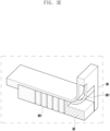
- FIG. 3D is a perspective view illustrating a protruding and retracting member 33, interlocking structure 34, a connecting member 35, and a guide 36 according to an embodiment of the disclosure.
- FIG. 3E is a cross-sectional view illustrating the protruding and retracting member 33, the connecting member 35, and the guide 36 according to an embodiment of the disclosure.
- FIG. 3F is a perspective view illustrating the protruding and retracting member 33 and the connecting member 35 according to an embodiment of the disclosure.
- FIG. 3D the first housing 31, the second housing 32, and a sliding rail 341 are omitted for clarity.
- the cross-section of FIG. 3E is a cross-section in A-A' direction of FIG. 3D .
- the electronic device 101 may include an interlocking structure 34, a connecting member 35, and a guide 36.
- the interlocking structure 34 may convert a sliding movement of the first housing 31 and the second housing 32 according to the withdrawal and retraction of the flexible display panel 161 into a lateral (represented in an y axis on the drawing) movement of the electronic device 101.
- the interlocking structure may be slidably coupled to at least one of the first housing 31 or the second housing 32 in at least one portion thereof.
- One end of the interlocking structure may be connected to a connecting member 35 to be described later.
- the interlocking structure 34 may include a link, cam, pinion, rail, and/or similar power transmission mechanism as a mechanism for converting a direction of a movement.
- the interlocking structure 34 of the electronic device 101 may include a sliding rail 341, a sliding block 342, and a link bar 343.
- the sliding rail 341 may be slidably coupled to a sliding block 342 to be described later and be disposed in the x-axis direction on an inner side surface of at least one of the first housing 31 or the second housing 32.
- the sliding block 342 and the link bar 343 may be rotatably connected to each other, and the link bar may be disposed at a first angle ⁇ with respect to the connecting member 35.
- the sliding rail 341 may be fixedly disposed at the second housing 32, and in other embodiments, the sliding rail 341 may be fixedly disposed at the first housing 31.
- the sliding rail 341 may include a groove 3411 formed on an inner side surface of at least one of the first housing 31 or the second housing 32.
- One end portion of the sliding block 342 may be slidably coupled to the sliding rail 341.
- the sliding rail 341 may prevent the sliding block 342 from moving in the y-axis direction with respect thereto and enable the sliding block 342 to move only in the x-axis direction.
- the other end portion of the sliding block 342 may be rotatably coupled to one end portion of the link bar 343 to be described later.
- the sliding block 342 may include a rotation shaft and/or a shaft hole for rotatable coupling with the link bar 343 at the other end portion.
- the link bar 343 may have one end portion rotatably coupled to the sliding block and the other end portion rotatably coupled to the connecting member 35.
- the link bar 343 may convert a direction of a force in the x-axis direction received by the sliding block into a force in the y-axis direction, and transfer the force to the connecting member 35.
- the connecting member 35 may be movably connected to the interlocking structure 34, be coupled to the protruding and retracting member 33 at one end, and be slidably coupled to a guide 36 to be described later. While the connecting member 35 receives a lateral movement converted by the interlocking structure 34 and is driven by it, the connecting member 35 may be guided by the guide 36 to move the protruding and retracting member 33 in the y-axis and z-axis directions on the drawing. Because the protruding and retracting member 33 is coupled to one end of the connecting member 35, the protruding and retracting member 33 may be moved to a position that may cover an exposed side surface of the flexible display panel 161 by a movement of the connecting member 35.
- the connecting member may include a flexible structure so that it may be guided by the guide 36.
- the connecting member 35 may have a multi-joint structure including a plurality of bars 351 rotatably connected to each other in order to have flexibility.
- the connecting member 35 may include a joint structure such as a barrel hinge, a flexible hinge, or a living hinge.
- a thickness of each bar 351 may be the same or different, as needed.
- the connecting member 35 and the protruding and retracting member may include guide blocks 353 and 333.
- the guide blocks 353 and 333 may be a structure for enabling the connecting member 35 to be slidably coupled to the guide 36 without being separated from the guide 36.
- the guide block may have a T-shaped, H-shaped, P-shaped or similar cross-section.
- the guide 36 may be fixed to the first housing 31, and the sliding rail 341 may be fixed to the second housing 32.
- the link bar 343 may apply a force by changing a direction of the force in the y-axis direction so that the connecting member 35 moves by being guided by the guide 36 using a force in the x-axis direction applied to the sliding block 342 by a relative movement of the second housing 32 with respect to the first housing 31.
- the guide 36 may be fixed to the second housing 32, and the sliding rail may be fixed to the first housing 31.
- the guide 36 may be slidably coupled to the connecting member 35. While limiting a movement of the connecting member 35 in the x-axis direction, the guide 36 may guide a moving direction of the connecting member 35 so as to protrude the protruding and retracting member 33 to a space between the first housing and the second housing as the connecting member 35 moves in lateral and vertical directions of the electronic device 101.
- the guide 36 may include a guide rail 361 slidably coupled to the guide block 353 of the connecting member 35 and configured to drive the connecting member in the y-axis and z-axis directions of the electronic device 101.
- the guide rail 361 may be a J-shaped rail including straight and curved sections.
- the guide rail 361 may include a groove formed on a surface of the guide 36 in contact with the connecting member 35 in a cross-sectional shape corresponding to a cross-section of the guide block 353.
- the guide rail 361 may include a T-shaped groove corresponding to the T-shaped cross section of the guide block 353.
- Shapes of the guide rail 361 and the guide block 353 of the electronic device according to the embodiment of this document are only an embodiment, and the disclosure is not limited thereto and may be formed in various shapes.
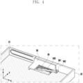
- FIG. 4 is an internal perspective view illustrating a protruding process of a protruding and retracting member 33 of the electronic device 101 according to an embodiment of the disclosure.
- the sliding block 342 in a state in which the flexible display panel 161 of the electronic device 101 is retracted, the sliding block 342 may be positioned at one end portion of the sliding rail 341 in the x-axis direction.
- the sliding block 342 when the second housing 32 moves in the x-axis direction with respect to the first housing 31 so as to draw out the flexible display panel 161 of the electronic device 101, the sliding block 342 may slide with respect to the sliding rail 341 to be positioned at the other end portion of the sliding rail 341.
- FIGS. 4A and 4B when the sliding block 342 moves from a state of FIG. 4A to a state of FIG.
- the sliding block 342 may move in the -x-axis direction with respect to the second housing.
- the sliding block 342 may receive a force in the x-axis direction at the other end portion of the sliding rail 341.
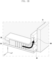
- FIG. 5A is an enlarged view illustrating an operation of the link bar 343 of the electronic device 101 according to an embodiment of the disclosure.
- FIG. 5B is a cross-sectional view illustrating an operation of the connecting member 35 and the guide 36 according to an embodiment of the disclosure.
- FIG. 5C is a cross-sectional view illustrating positions of the connecting member 35 and the guide 36 in a state in which the protruding and retracting member 33 is protruded according to an embodiment of the disclosure.
- FIGS. 5B and 5C are cross sections cut along A-A' direction of FIG. 5A .
- the link bar 343 may be rotatably coupled to each of the sliding block 342 and the connecting member 35 and be disposed at a first angle ⁇ with respect to the connecting member 35.
- the sliding block 342 may be coupled to one end away from the center of the link bar 343 to apply a rotational force to the link bar 343.
- the rotational force of the link bar 343 may be converted and applied to a force of a y-axis direction with respect to the connecting member 35 coupled to the other end portion of the link bar.
- the connecting member 35 may be rotatably coupled to the link bar 343 and operated by a force converted by the link bar 343 in the y-axis direction.
- the guide rail 361 of the guide 36 provides a curved path for converting a movement of the connecting member 35 in the y-axis direction to the z-axis direction.
- the guide rail 361 may include a J-shaped curved path. The connecting member 35 moves along a J-shaped curved path by the guide rail 361, thereby protruding the protruding and retracting member 33 coupled to one end of the connecting member 35 into the space between the first housing and the second housing.
- the protruded protruding and retracting member 33 may exist in a location that covers a lateral portion of the flexible display panel 161 exposed to the space between the first housing 31 and the second housing 32 in a state in which the flexible display panel 161 is drawn out.
- FIG. 6A is a perspective view illustrating a sliding rail 341 according to an embodiment of the disclosure.
- FIG. 6B is a cross-sectional view illustrating actions of the sliding rail 341, the sliding block 342, and a sliding limiting member 3412 during a withdrawal operation.
- FIG. 6C is a cross-sectional view illustrating actions of the sliding rail 341, the sliding block 342, and the sliding limiting member 3412 during a retraction operation.
- FIGS. 6B and 6C represent a relative movement of the sliding block 342 with respect to the sliding rail 341.
- the sliding rail 341 may include a sliding limiting member 3412.
- the sliding limiting member may be disposed on the sliding rail 341 to be close to a distal end portion in a direction in which the flexible display panel 161 is retracted (-x direction in the drawing).
- the sliding limiting member 3412 may include a protrusion formed on an inner surface of the groove 3411 formed at an inner surface of the first housing or the second housing.
- the sliding limiting member 3412 may provide a low resistance force to a sliding movement between the sliding block 342 and the sliding rail 341. Therefore, the sliding block 342 may easily pass through the sliding limiting member 3412 to reach a distal end portion of the sliding rail 341.
- the sliding limiting member 3412 may provide a high resistance force to the sliding movement between the sliding block 342 and the sliding rail 341. Therefore, the sliding block 342 may not easily pass through the sliding limiting member 3412, and the sliding block 342 may receive a force from the second housing in the -x direction. The force received by the sliding block 342 in the -x direction may drive the link bar 343 and the connecting member 35 so that the protruding and retracting member is retracted into the electronic device 101.
- an end portion in the -x direction may have a shape that is easy to pass through the sliding limiting member 3412, and an end portion in the opposite direction may have an shape that is unfavorable for passing through the sliding limiting member 3412.
- the sliding block 342 may include a chamfering or rounding (R) shape with respect to a corner at an end portion in the -x direction, and maintain a corner shape with small or no chamfering or rounding value at an end portion in the opposite direction.
- the sliding block 342 and the sliding limiting member 3412 may include a bump structure having a lateral symmetric inclined surface.
- the sliding limiting member 3412 may include an asymmetrical movement limiting mechanism such as a ratchet.
- FIG. 7 is an internal perspective view illustrating a retraction action of the protruding and retracting member 33 according to an embodiment of the disclosure.
- the link bar 343 in a state in which the protruding and retracting member 33 is protruded, the link bar 343 may be disposed at a second angle ⁇ with respect to the connecting member 35.
- the second angle ⁇ may be smaller than a first angle ⁇ , which is an angle formed by the link bar 343 and the connecting member 35 in a state in which the protruding and retracting member 33 is retracted.
- the sliding limiting member 3412 may provide a high resistance force to a sliding movement between the sliding block 342 and the sliding rail 341. Therefore, the sliding block 342 may not easily pass through the sliding limiting member 3412, but receive a force from the second housing in the -x direction. Accordingly, the sliding block 342 may drive the link bar 343 and the connecting member in a direction in which the protruding and retracting member is retracted into the electronic device 101. After the driving of the connecting member is completed, when an additional force is applied to the second housing, the sliding block 342 may pass through the sliding limiting member 3412 and move on the sliding rail 341.
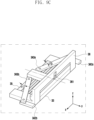
- FIG. 8A is an internal perspective view illustrating a connecting member 35 and an interlocking structure 34 of the electronic device 101 according to another embodiment of the disclosure.
- FIG. 8B is a perspective view illustrating a connecting member 35, a link bar 343, and an interlocking structure 34 of the electronic device 101 according to another embodiment of the disclosure.
- the connecting member 35 may include a plurality of bars 351 disposed in parallel and a flat connecting member 352 having one surface perpendicular to the bar 351 on a plane.
- the side parallel to the bar 351 may be coupled to the bar 351 so that the connecting member 35 may have flexibility, and the side perpendicular to the bar 351 may be rotatably coupled to the link bar 343.
- the flat connecting member 352 and the sliding block 342 may include coupling grooves 3521 and 3421, respectively to which both end portions of the link bar 343 may be rotatably coupled.
- each of the coupling grooves 3521 and 3421 may include a shaft hole for rotatably coupling both end portions of the link bar 343.
- the L-shaped flat connection member 352 is an embodiment for reducing a mounting space, and the disclosure is not limited thereto, and the flat connection member 352 may include various shapes for coupling with the link bar on a plane.
- the flat connecting member 352 may have a simple rectangular shape or a T-shape according to a position connecting the connecting member 35 and the link bar 343, and two sides of the flat connecting member 352 may form an acute angle or an obtuse angle not 90 degrees.
- both ends of the link bar 343 are inserted into the coupling grooves 3521 and 3421 to be rotatably coupled to the coupling grooves 3521 and 3421; thus, the link bar 343, the sliding block 342, and the flat connecting member 352 may be positioned at a the same height.
- Such a constitution has the advantage capable of minimizing a thickness required for mounting inside the electronic device 101 by reducing the overall height of the interlocking structure 34.
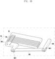
- FIG. 9A is a perspective view illustrating the inside of the electronic device 101 in a state in which the flexible display panel 161 of the electronic device 101 is retracted according to another embodiment of the disclosure.
- FIG. 9B is a perspective view illustrating the inside of the electronic device 101 in a state in which the flexible display panel 161 of the electronic device 101 is drawn out according to another embodiment of the disclosure.
- FIG. 9C is a perspective view illustrating the electronic device 101 according to another embodiment of the disclosure.
- an interlocking structure 34 of the electronic device 101 may include a first sliding rail 341a, a second sliding rail 341b, a first sliding block 342a, a second sliding block 342b, a first link bar 343a, and a second link bar 343b.
- the first sliding rail 341a may include a first groove 3411a formed at an inner side surface of the first housing 31, and the second sliding rail 341b may include a second groove 3411b formed at an inner side surface of the second housing 32.
- a length of the first sliding rail 341a may be shorter than that of the second sliding rail 341b. In another embodiment, a length of the second sliding rail 341b may be shorter than that of the first sliding rail 341a.
- the first sliding block 342a and the second sliding block 342b may be slidably coupled to the first sliding rail 341a and the second sliding rail 341b, respectively.
- the first link bar 343a and the second link bar 343b may have one end portions rotatably coupled to the first sliding block 342a and the second sliding block 342b, respectively, and the other end portions rotatably coupled to the connecting member 35.
- the first link bar 343a and the second link bar 343b may be disposed to form a first angle ⁇ and a third angle ⁇ with the connecting member 35, respectively in a direction in which the other end portions face each other.
- Magnitudes of the first angle ⁇ and the third angle ⁇ may be determined according to lengths of the first link bar 343a and the second link bar 343b, positions in which the first link bar 343a and the second link bar 343b are coupled to the connecting member 35, and positions of the first sliding block 342a and the second sliding block 342b.
- the first angle ⁇ and the third angle ⁇ may be substantially the same, and the first link bar 343a and the second link bar 343b may be symmetrically disposed with respect to the yz plane.
- the guide 36 may include a guide rail 361 disposed at the center thereof, and the connecting member 35 may include a guide block 353 disposed at a position corresponding to that of the guide rail 361.
- the first link bar 343a and the second link bar 343b may be rotatably coupled to the connecting member 35 at a point forming left-right symmetry around the guide block 353 of the connecting member 35.
- the first housing 31 and the second housing 32 may have a first guide seating portion 311 and a second guide seating portion 321, respectively.
- the first guide seating portion 311 and the second seating portion 321 may include grooves formed on inner bottom surfaces of the first housing 31 and the second housing 32.
- the guide 36 may be slidably disposed with respect to the first guide seating portion 311 and the second guide seating portion 321.
- the first housing 31 and the second housing 32 slide in the -x-axis and x-axis direction based on the guide 36, respectively, and the first sliding block 342a and the second sliding block 342b reach both end portions.
- the first sliding block 342a and the second sliding block 342b receive a force in the -x and x-axis directions, respectively, and this is transferred by the first link bar 343a and the second link bar 343b to apply a force to the connecting member 35 in the y-axis direction.
- the force applied to the connecting member 35 is symmetrical, and an unbalanced force is thus applied to the connecting member 35 in the x or -x-axis direction to prevent a frictional force between the guide rail 361 and the guide block 353 from increasing.
- FIG. 10A is an internal perspective view illustrating a foreign material blocking member 37 in a state in which the flexible display panel 161 of the electronic device 101 is retracted according to another embodiment of the disclosure.
- FIG. 10B is an internal perspective view illustrating a foreign material blocking member 37 in a state in which the flexible display panel 161 of the electronic device 101 is drawn out according to another embodiment of the disclosure.
- FIG. 10C is a side view illustrating a foreign material blocking member 37 in a state in which the flexible display panel 161 of the electronic device 101 is drawn out and in which a protruding and retracting member 33 is protruded according to another embodiment of the disclosure.
- FIG. 10C is a side view taken based on the y-axis direction of FIG. 10B .
- the electronic device 101 may include a foreign material blocking member 37.
- the foreign material blocking member 37 may be fixedly coupled to either the first housing 31 or the second housing 32 and be slidable coupled to the other one of the first housing 31 or the second housing 32.
- the other one of the first housing 31 or the second housing 32 may include a groove 371 formed at a bottom surface in order to guide the foreign material blocking member 37 during a sliding motion.
- an upper surface (referring to a surface facing the z-axis direction in the drawing) of the foreign material blocking member 37 may slidably contact the guide 36 and the connecting member 35.
- the foreign material blocking member 37 may fill a gap existing between the guide 36 and the connecting member 35 and the first housing 31 or the second housing 32 to block an outer foreign material from being introduced into the electronic device 101 in a state in which the flexible display panel 161 is drawn out.
- the foreign material blocking member 37 may be a seal, sweeper, or scraper including rubber, nitrile-butadiene rubber (NBR), silicone, or similar elastic materials.
- an electronic device may include a first housing; a second housing slidably coupled to the first housing; a flexible display panel retracted into and drawn out from the electronic device by a sliding motion between the first housing and the second housing; a protruding and retracting member protruded to a space between lateral portions of the first housing and the second housing generated at a side surface of the flexible display panel or retracted into the electronic device from the space when the flexible display panel is drawn out or retracted; an interlocking structure coupled to at least one of the first housing or the second housing and configured to convert the sliding motion into a lateral movement of the electronic device; a connecting member having flexibility configured such that one end thereof is coupled to one end of the protruding and retracting member and the other end thereof is connected to the interlocking structure to be movable along the lateral movement; and a guide positioned in at least one of the first housing or the second housing and configured to convert the lateral movement of the connecting member generated by an action of the interlocking structure
- the interlocking structure may include a sliding rail disposed on an inner side surface of at least one of the first housing or the second housing; a sliding block having one end portion slidably coupled to the sliding rail; and at least one link bar having one end portion rotatably coupled to the other end portion of the sliding block and the other end portion rotatably connected to the connecting member.
- the sliding rail may include a groove formed on an inner side surface of the first housing, and the guide may be fixedly disposed at the second housing at a lateral portion exposed to the outside during the withdrawing operation of the second housing.
- the sliding rail may include a groove formed on an inner side surface of the second housing, and the guide may be fixedly disposed at the first housing at a lateral portion exposed to the outside during a withdrawing operation of the first housing.
- the sliding rail may include a first sliding rail including a first groove formed on an inner side surface of the first housing and a second sliding rail including a second groove formed on an inner side surface of the second housing
- the sliding block may include a first sliding block slidably coupled to the first sliding rail and a second sliding block slidably coupled to the second sliding rail
- the link bar may include a first link bar having one end portion rotatably coupled to the other end portion of the first sliding block and the other end portion rotatably connected to the other end portion of the connecting member and a second link bar having one end portion rotatably coupled to the other end portion of the second sliding block and the other end portion rotatably connected to the other end portion of the connecting member, wherein the first link bar and the second link may be disposed to face each other based on a center line of the connecting member.
- the electronic device may further include a foreign material blocking member in contact with a lower part of the connecting member, slidably coupled on an inner surface of the first housing or the second housing, and configured to block a gap existing between the lower part of the connecting member and an inner surface of the first housing or the second housing to prevent a foreign material from being introduced into the electronic device.
- a foreign material blocking member in contact with a lower part of the connecting member, slidably coupled on an inner surface of the first housing or the second housing, and configured to block a gap existing between the lower part of the connecting member and an inner surface of the first housing or the second housing to prevent a foreign material from being introduced into the electronic device.
- the sliding rail may include a sliding limiting member disposed close to an end portion in a direction in which the flexible display panel is retracted on a surface thereof and configured to apply a resistance force to a sliding movement therebetween with respect to the sliding block, and the sliding limiting member may have an asymmetrical resistance force that provides a low resistance force to a sliding movement of the sliding block when an operation of withdrawing the flexible display panel is performed and that provides a high resistance force to the sliding movement of the sliding block in an operation of retracting the flexible display panel.
- the connecting member may include a multi-bar structure including a plurality of bars disposed in parallel with each other and rotatably connected to each other.
- the connecting member may have one side disposed parallel to the bar and the other side disposed at a specific angle with the one side on a plane, and the other side may have a flat connecting member rotatably connected to the other end portion of the link bar.
- the sliding block may include a groove formed in the other end portion so that the one end portion of the link bar may be rotatably fitted, and the flat connecting member may include a groove formed to be rotatably fitted with the other end portion of the link bar at a distal end portion of the other side.
- the connecting member may include a plurality of guide blocks formed at one side of each of the plurality of bars, and the guide may include a guide rail slidably coupled to the plurality of guide blocks.
- the guide block may have a T-shaped cross-section, and the guide rail may have a cross-sectional shape corresponding to a cross-sectional shape of the guide block.
- the protruding and retracting member may be a side wall protecting a side surface of the flexible display panel.
- the protruding and retracting member may include or be connected to a wireless transceiver, and the wireless transceiver included in or connected to the protruding and retracting member by a sliding motion may change a position thereof inside the electronic device or be exposed to a space between the first housing and the second housing to improve a wireless reception performance.
Landscapes
- Engineering & Computer Science (AREA)
- Theoretical Computer Science (AREA)
- Computer Hardware Design (AREA)
- Physics & Mathematics (AREA)
- General Physics & Mathematics (AREA)
- Human Computer Interaction (AREA)
- General Engineering & Computer Science (AREA)
- Mathematical Physics (AREA)
- Signal Processing (AREA)
- Devices For Indicating Variable Information By Combining Individual Elements (AREA)
Claims (14)
- Elektronische Vorrichtung (101), umfassend:ein erstes Gehäuse (31);ein zweites Gehäuse (32), das verschiebbar an das erste Gehäuse (31) gekoppelt ist;eine flexible Anzeigetafel (161), die durch eine Schiebebewegung zwischen dem ersten Gehäuse (31) und dem zweiten Gehäuse (32) in die elektronische Vorrichtung zurückgezogen und daraus herausgezogen wird;wobei die elektronische Vorrichtung (101) dadurch gekennzeichnet ist, dass sie ferner Folgendes umfasst:ein vorstehendes und zurückziehendes Element (33), das zu einem Raum zwischen seitlichen Abschnitten des ersten Gehäuses (31) und des zweiten Gehäuses (32) vorsteht, der an einer Seitenoberfläche der flexiblen Anzeigetafel (161) erzeugt wird, wenn die flexible Anzeigetafel (161) aus dem Raum aus der elektronischen Vorrichtung herausgezogen und darin zurückgezogen wird, wenn die flexible Anzeigetafel zurückgezogen wird;eine Verriegelungsstruktur (34), die an zumindest eines von dem ersten Gehäuse (31) oder dem zweiten Gehäuse (32) gekoppelt und konfiguriert ist, um die Schiebebewegung in eine seitliche Bewegung umzuwandeln;ein Verbindungselement (35) mit Flexibilität, das derart konfiguriert ist, dass ein Ende davon an ein Ende des vorstehenden und zurückziehenden Elements (33) gekoppelt ist und das andere Ende davon mit der Verriegelungsstruktur (34) verbunden ist, um entlang der seitlichen Bewegung bewegbar zu sein; undeine Führung (36), die in zumindest einem von dem ersten Gehäuse (31) oder dem zweiten Gehäuse (32) positioniert und konfiguriert ist, um die seitliche Bewegung des Verbindungselements (35), die durch eine Wirkung der Verriegelungsstruktur (34) erzeugt wird, in eine vertikale Bewegung umzuwandeln.
- Elektronische Vorrichtung nach Anspruch 1, wobei die Verriegelungsstruktur (34) Folgendes umfasst:eine Schiebeschiene (341), die an einer inneren Seitenoberfläche von zumindest einem von dem ersten Gehäuse (31) oder dem zweiten Gehäuse (32) angeordnet ist;einen Schiebeblock (342), der einen Endabschnitt aufweist, der verschiebbar an die Schiebeschiene gekoppelt ist; undzumindest eine Verknüpfungsstange (343), die einen Endabschnitt aufweist, der drehbar an den anderen Endabschnitt des Schiebeblocks (342) gekoppelt ist und wobei der andere Endabschnitt drehbar mit dem Verbindungselement (35) verbunden ist.
- Elektronische Vorrichtung nach Anspruch 2, wobei die Schiebeschiene (341) eine Nut umfasst, die an einer inneren Seitenoberfläche des ersten Gehäuses (31) gebildet ist, und
die Führung (36) fest an dem zweiten Gehäuse (32) an einem seitlichen Abschnitt angeordnet ist, welcher der Außenseite während des Rückzugsvorgangs des zweiten Gehäuses (32) ausgesetzt ist. - Elektronische Vorrichtung nach Anspruch 2, wobei die Schiebeschiene (341) eine Nut umfasst, die an einer inneren Seitenoberfläche des zweiten Gehäuses (32) gebildet ist, und
die Führung (36) fest an dem ersten Gehäuse (31) an einem seitlichen Abschnitt angeordnet ist, welcher der Außenseite während eines Rückzugsvorgangs des ersten Gehäuses (31) ausgesetzt ist. - Elektronische Vorrichtung nach Anspruch 2, wobei die Schiebeschiene (341) eine erste Schiebeschiene (341a), die eine erste Nut beinhaltet, die an einer inneren Seitenoberfläche des ersten Gehäuses (31) gebildet ist, und eine zweite Schiebeschiene (341b), die eine zweite Nut beinhaltet, die an einer inneren Seitenoberfläche des zweiten Gehäuses (32) gebildet ist, umfasst,der Schiebeblock (342) einen ersten Schiebeblock (342a), der verschiebbar an die erste Schiebeschiene (341a) gekoppelt ist, und einen zweiten Schiebeblock (342b), der verschiebbar an die zweite Schiebeschiene (341b) gekoppelt ist, umfasst,die Verknüpfungsstange (343) eine erste Verknüpfungsstange (343a), die einen Endabschnitt aufweist, der drehbar an den anderen Endabschnitt des ersten Schiebeblocks (342a) gekoppelt ist, und wobei der andere Endabschnitt drehbar mit dem anderen Endabschnitt des Verbindungselements (35) verbunden ist, und eine zweite Verknüpfungsstange (343b), die einen Endabschnitt aufweist, der drehbar an den anderen Endabschnitt des zweiten Schiebeblocks (342b) gekoppelt ist, und wobei der andere Endabschnitt drehbar mit dem anderen Endabschnitt des Verbindungselements (35) verbunden ist, umfasst,wobei die erste Verknüpfungsstange (343a) und die zweite Verknüpfungsstange (343b) angeordnet sind, um einander basierend auf einer Mittellinie des Verbindungselements (35) zugewandt zu sein.
- Elektronische Vorrichtung nach Anspruch 5, ferner umfassend ein Fremdmaterialblockierelement (37) in Kontakt mit einem unteren Teil des Verbindungselements (35), das verschiebbar an einer inneren Oberfläche des ersten Gehäuses (31) oder des zweiten Gehäuses (32) gekoppelt und konfiguriert ist, um einen Spalt zu blockieren, der zwischen dem unteren Teil des Verbindungselements (35) und einer inneren Oberfläche des ersten Gehäuses (31) oder des zweiten Gehäuses (32) besteht, um zu verhindern, dass ein Fremdmaterial in die elektronische Vorrichtung eingeführt wird.
- Elektronische Vorrichtung nach Anspruch 2, wobei die Schiebeschiene (341) ein Schiebebegrenzungselement (3412) umfasst, das nahe einem Endabschnitt in einer Richtung angeordnet ist, in der die flexible Anzeigetafel (161) auf einer Oberfläche davon zurückgezogen ist, und konfiguriert ist, um eine Widerstandskraft auf eine Schiebebewegung dazwischen in Bezug auf den Schiebeblock auszuüben,
wobei das Schiebebegrenzungselement (3412) eine asymmetrische Widerstandskraft aufweist, die einer Schiebebewegung des Schiebeblocks (342) eine geringe Widerstandskraft bereitstellt, wenn ein Vorgang des Rückzugs der flexiblen Anzeigetafel (161) durchgeführt wird, und die der Schiebebewegung des Schiebeblocks (342) bei einem Vorgang des Zurückziehens der flexiblen Anzeigetafel (161) eine hohe Widerstandskraft bereitstellt. - Elektronische Vorrichtung nach Anspruch 2, wobei das Verbindungselement (35) eine Multistangenstruktur umfasst, die eine Vielzahl von Stangen (351) beinhaltet, die parallel zueinander angeordnet und drehbar miteinander verbunden ist.
- Elektronische Vorrichtung nach Anspruch 8, wobei das Verbindungselement (35) eine Seite aufweist, die parallel zu der Stange angeordnet ist, und die andere Seite in einem spezifischen Winkel mit der einen Seite auf einer Ebene angeordnet ist, und die andere Seite ein flaches Verbindungselement (352) aufweist, das drehbar mit dem anderen Endabschnitt der Verknüpfungsstange (343) verbunden ist.
- Elektronische Vorrichtung nach Anspruch 9, wobei der Schiebeblock (342) eine Nut umfasst, die in dem anderen Endabschnitt gebildet ist, sodass der eine Endabschnitt der Verknüpfungsstange (343) drehbar angebracht sein kann, und
das flache Verbindungselement (352) eine Nut umfasst, die gebildet ist, um drehbar mit dem anderen Endabschnitt der Verknüpfungsstange (343) an einem distalen Endabschnitt der anderen Seite angebracht zu sein. - Elektronische Vorrichtung nach Anspruch 8, wobei das Verbindungselement (35) eine Vielzahl von Führungsblöcken (353, 333) umfasst, die an einer Seite von jeder aus der Vielzahl von Stangen (351) gebildet ist, und
die Führung (36) eine Führungsschiene (361) umfasst, die verschiebbar an die Vielzahl von Führungsblöcken (353, 333) gekoppelt ist. - Elektronische Vorrichtung nach Anspruch 11, wobei der Führungsblock (353, 333) einen T-förmigen Querschnitt aufweist und
die Führungsschiene (361) eine Querschnittsform aufweist, die einer Querschnittsform des Führungsblocks (353, 333) entspricht. - Elektronische Vorrichtung nach Anspruch 1, wobei das vorstehende und zurückziehende Element (33) eine Seitenwand ist, die eine Seitenoberfläche der flexiblen Anzeigetafel (161) schützt.
- Elektronische Vorrichtung nach Anspruch 1, wobei das vorstehende und zurückziehende Element (33) einen drahtlosen Sendeempfänger (331) umfasst oder damit verbunden ist, und
der drahtlose Sendeempfänger (331), der in dem vorstehenden und zurückziehenden Element (33) beinhaltet oder damit verbunden ist, durch eine Schiebebewegung eine Position davon innerhalb der elektronischen Vorrichtung ändert oder einem Raum zwischen dem ersten Gehäuse (31) und dem zweiten Gehäuse (32) ausgesetzt ist, um eine drahtlose Empfangsleistung zu verbessern.
Applications Claiming Priority (3)
| Application Number | Priority Date | Filing Date | Title |
|---|---|---|---|
| KR20200167995 | 2020-12-04 | ||
| KR1020210062067A KR102913224B1 (ko) | 2020-12-04 | 2021-05-13 | 슬라이더블 전자 장치 |
| PCT/KR2021/018377 WO2022119421A1 (ko) | 2020-12-04 | 2021-12-06 | 슬라이더블 전자 장치 |
Publications (3)
| Publication Number | Publication Date |
|---|---|
| EP4239444A1 EP4239444A1 (de) | 2023-09-06 |
| EP4239444A4 EP4239444A4 (de) | 2024-05-01 |
| EP4239444B1 true EP4239444B1 (de) | 2025-02-26 |
Family
ID=81853376
Family Applications (1)
| Application Number | Title | Priority Date | Filing Date |
|---|---|---|---|
| EP21901109.5A Active EP4239444B1 (de) | 2020-12-04 | 2021-12-06 | Verschiebbare elektronische vorrichtung |
Country Status (3)
| Country | Link |
|---|---|
| US (1) | US12493320B2 (de) |
| EP (1) | EP4239444B1 (de) |
| WO (1) | WO2022119421A1 (de) |
Families Citing this family (3)
| Publication number | Priority date | Publication date | Assignee | Title |
|---|---|---|---|---|
| CN113938545B (zh) * | 2021-10-13 | 2023-09-22 | 维沃移动通信有限公司 | 电子设备 |
| CN117672082A (zh) * | 2022-09-07 | 2024-03-08 | Oppo广东移动通信有限公司 | 电子装置 |
| CN119641783A (zh) * | 2023-09-18 | 2025-03-18 | 富世达股份有限公司 | 铰链 |
Family Cites Families (32)
| Publication number | Priority date | Publication date | Assignee | Title |
|---|---|---|---|---|
| US7035090B2 (en) * | 2003-09-04 | 2006-04-25 | Kabushiki Kaisha Toshiba | Interlocking mechanism for a display |
| US8199471B2 (en) * | 2004-10-05 | 2012-06-12 | Creator Technology B.V. | Rollable display device |
| KR20120079493A (ko) | 2010-12-23 | 2012-07-13 | 주식회사 팬택 | 휴대 단말기 |
| US9286812B2 (en) * | 2011-06-07 | 2016-03-15 | Microsoft Technology Licensing, Llc | Flexible display extendable assembly |
| US8711566B2 (en) | 2011-09-02 | 2014-04-29 | Microsoft Corporation | Expandable mobile device |
| US20130120912A1 (en) * | 2011-11-15 | 2013-05-16 | Research In Motion Limited | Handheld electronic device having a flexible display |
| KR102066716B1 (ko) * | 2013-06-20 | 2020-01-15 | 삼성전자주식회사 | 동작 방법 및 그 전자 장치 |
| EP3087559B1 (de) * | 2013-12-24 | 2021-05-05 | Flexterra, Inc. | Stützstrukturen für ein flexibles elektronisches bauteil |
| KR102339290B1 (ko) * | 2014-12-16 | 2021-12-15 | 삼성디스플레이 주식회사 | 표시 장치 |
| US10481638B2 (en) * | 2015-11-18 | 2019-11-19 | Semiconductor Energy Laboratory Co., Ltd. | Electronic device |
| KR102470945B1 (ko) * | 2016-06-15 | 2022-11-25 | 엘지전자 주식회사 | 이동 단말기 |
| WO2018056749A1 (ko) * | 2016-09-22 | 2018-03-29 | 민상규 | 접이식 가상현실 장비 |
| KR102627801B1 (ko) * | 2016-10-10 | 2024-01-22 | 삼성디스플레이 주식회사 | 확장형 표시 장치 |
| KR20190004618A (ko) * | 2017-07-04 | 2019-01-14 | 신진철 | 슬라이딩 구동에 의한 화면 확장형 이동 단말기 |
| KR102369318B1 (ko) | 2017-08-30 | 2022-03-02 | 엘지디스플레이 주식회사 | 연성 디스플레이 장치 |
| CN111819615B (zh) | 2018-02-09 | 2022-05-17 | 深圳市柔宇科技股份有限公司 | 柔性显示装置 |
| CN111819616A (zh) | 2018-02-09 | 2020-10-23 | 深圳市柔宇科技股份有限公司 | 柔性显示装置 |
| KR102266152B1 (ko) * | 2018-02-22 | 2021-06-17 | 삼성전자주식회사 | 디스플레이 영역의 크기 변경이 가능한 플렉시블 디스플레이를 포함하는 전자 장치 및 그 제어 방법 |
| KR102486663B1 (ko) * | 2018-06-19 | 2023-01-11 | 삼성전자 주식회사 | 플렉서블 디스플레이 및 안테나를 포함하는 전자 장치 |
| US10809767B2 (en) * | 2018-10-25 | 2020-10-20 | Google Llc | Electronic device with flexible display |
| US11165897B2 (en) * | 2019-02-14 | 2021-11-02 | Lg Electronics Inc. | Roll-slide mobile terminal |
| KR102845067B1 (ko) * | 2019-02-14 | 2025-08-13 | 엘지전자 주식회사 | 이동 단말기 |
| KR102834302B1 (ko) | 2019-03-18 | 2025-07-15 | 엘지전자 주식회사 | 롤-슬라이드 이동 단말기 |
| EP3942786B1 (de) * | 2019-03-18 | 2024-10-23 | LG Electronics Inc. | Mobiles endgerät |
| US11071218B2 (en) * | 2019-04-10 | 2021-07-20 | Apple Inc. | Electronic devices having sliding expandable displays |
| EP3955236B1 (de) * | 2019-04-11 | 2023-11-15 | LG Electronics Inc. | Flexible anzeigevorrichtung |
| KR102154933B1 (ko) * | 2019-08-03 | 2020-09-10 | 주식회사 탑시스템 | 디스플레이 승강기의 이물질 차단시스템 |
| WO2021025210A1 (ko) * | 2019-08-08 | 2021-02-11 | 엘지전자 주식회사 | 플렉서블 디스플레이 장치 |
| EP3974940B1 (de) * | 2019-09-11 | 2024-10-09 | Samsung Electronics Co., Ltd. | Stützschiene für elektronische vorrichtung |
| WO2021149844A1 (ko) * | 2020-01-21 | 2021-07-29 | 엘지전자 주식회사 | 콘텐츠를 표시하는 전자 장치 및 그 제어 방법 |
| WO2021177482A1 (ko) * | 2020-03-03 | 2021-09-10 | 엘지전자 주식회사 | 디스플레이의 크기를 제어하는 전자 장치 및 그 제어 방법 |
| US12267451B2 (en) * | 2020-08-27 | 2025-04-01 | Lg Electronics Inc. | Flexible display device |
-
2021
- 2021-12-06 EP EP21901109.5A patent/EP4239444B1/de active Active
- 2021-12-06 WO PCT/KR2021/018377 patent/WO2022119421A1/ko not_active Ceased
-
2023
- 2023-06-02 US US18/328,409 patent/US12493320B2/en active Active
Also Published As
| Publication number | Publication date |
|---|---|
| US20230315147A1 (en) | 2023-10-05 |
| WO2022119421A1 (ko) | 2022-06-09 |
| US12493320B2 (en) | 2025-12-09 |
| EP4239444A4 (de) | 2024-05-01 |
| EP4239444A1 (de) | 2023-09-06 |
Similar Documents
| Publication | Publication Date | Title |
|---|---|---|
| US20220294886A1 (en) | Multi-foldable electronic device | |
| US12493320B2 (en) | Slideable electronic device | |
| KR102913224B1 (ko) | 슬라이더블 전자 장치 | |
| US20230053373A1 (en) | Hinge assembly and electronic device including the same | |
| US11547008B2 (en) | Electronic device including magnetic structure | |
| US12457697B2 (en) | Flexible display, structure supporting the flexible display, and electronic device including the same | |
| EP4407405A1 (de) | Faltbare elektronische vorrichtung mit einem nichtleitenden element | |
| US12494812B2 (en) | Electronic device including magnets | |
| US20230176629A1 (en) | Hinge assembly and electronic device including the same | |
| US20230213967A1 (en) | Flexible display and electronic device including same | |
| US20250211667A1 (en) | Electronic device with waterproof structure | |
| US20240121907A1 (en) | Electronic device capable of sliding and folding operations | |
| US12229365B2 (en) | Electronic device including shielding member | |
| US20250348166A1 (en) | Electronic device and method for recognizing input to flexible display | |
| AU2021426185B2 (en) | Display module capable of recognizing pen input device, and electronic device comprising display module | |
| KR102875435B1 (ko) | 플렉서블 디스플레이를 포함하는 전자 장치 | |
| EP4270144A1 (de) | Elektronische vorrichtung mit mikrofonmodul | |
| EP4642017A1 (de) | Elektronische vorrichtung mit flexibler anzeige und verfahren zur identifizierung eines gefalteten oder nicht gefalteten zustands | |
| US20250047768A1 (en) | Electronic device comprising structure for supporting flexible printed circuit board | |
| US20250350674A1 (en) | Electronic device including structure for reducing damage to display | |
| US20260107390A1 (en) | Electronic device including capacitor array for connection of display driver ic | |
| US20260039733A1 (en) | Foldable electronic device comprising charging coil and magnet | |
| US20240431048A1 (en) | Rollable electronic device comprising guide assembly | |
| US20240284619A1 (en) | Electronic device comprising driving element | |
| US20240029469A1 (en) | Electronic apparatus comprising piezoelectric module |
Legal Events
| Date | Code | Title | Description |
|---|---|---|---|
| STAA | Information on the status of an ep patent application or granted ep patent |
Free format text: STATUS: THE INTERNATIONAL PUBLICATION HAS BEEN MADE |
|
| PUAI | Public reference made under article 153(3) epc to a published international application that has entered the european phase |
Free format text: ORIGINAL CODE: 0009012 |
|
| STAA | Information on the status of an ep patent application or granted ep patent |
Free format text: STATUS: REQUEST FOR EXAMINATION WAS MADE |
|
| 17P | Request for examination filed |
Effective date: 20230602 |
|
| AK | Designated contracting states |
Kind code of ref document: A1 Designated state(s): AL AT BE BG CH CY CZ DE DK EE ES FI FR GB GR HR HU IE IS IT LI LT LU LV MC MK MT NL NO PL PT RO RS SE SI SK SM TR |
|
| DAV | Request for validation of the european patent (deleted) | ||
| DAX | Request for extension of the european patent (deleted) | ||
| A4 | Supplementary search report drawn up and despatched |
Effective date: 20240328 |
|
| RIC1 | Information provided on ipc code assigned before grant |
Ipc: H04M 1/02 20060101ALI20240322BHEP Ipc: G09F 9/30 20060101ALI20240322BHEP Ipc: G06F 1/16 20060101AFI20240322BHEP |
|
| GRAP | Despatch of communication of intention to grant a patent |
Free format text: ORIGINAL CODE: EPIDOSNIGR1 |
|
| STAA | Information on the status of an ep patent application or granted ep patent |
Free format text: STATUS: GRANT OF PATENT IS INTENDED |
|
| RIC1 | Information provided on ipc code assigned before grant |
Ipc: H04M 1/02 20060101ALI20240902BHEP Ipc: G09F 9/30 20060101ALI20240902BHEP Ipc: G06F 1/16 20060101AFI20240902BHEP |
|
| INTG | Intention to grant announced |
Effective date: 20240919 |
|
| GRAS | Grant fee paid |
Free format text: ORIGINAL CODE: EPIDOSNIGR3 |
|
| GRAA | (expected) grant |
Free format text: ORIGINAL CODE: 0009210 |
|
| STAA | Information on the status of an ep patent application or granted ep patent |
Free format text: STATUS: THE PATENT HAS BEEN GRANTED |
|
| AK | Designated contracting states |
Kind code of ref document: B1 Designated state(s): AL AT BE BG CH CY CZ DE DK EE ES FI FR GB GR HR HU IE IS IT LI LT LU LV MC MK MT NL NO PL PT RO RS SE SI SK SM TR |
|
| REG | Reference to a national code |
Ref country code: GB Ref legal event code: FG4D |
|
| REG | Reference to a national code |
Ref country code: CH Ref legal event code: EP |
|
| REG | Reference to a national code |
Ref country code: DE Ref legal event code: R096 Ref document number: 602021026939 Country of ref document: DE |
|
| REG | Reference to a national code |
Ref country code: IE Ref legal event code: FG4D |
|
| REG | Reference to a national code |
Ref country code: NL Ref legal event code: MP Effective date: 20250226 |
|
| PG25 | Lapsed in a contracting state [announced via postgrant information from national office to epo] |
Ref country code: RS Free format text: LAPSE BECAUSE OF FAILURE TO SUBMIT A TRANSLATION OF THE DESCRIPTION OR TO PAY THE FEE WITHIN THE PRESCRIBED TIME-LIMIT Effective date: 20250526 |
|
| PG25 | Lapsed in a contracting state [announced via postgrant information from national office to epo] |
Ref country code: FI Free format text: LAPSE BECAUSE OF FAILURE TO SUBMIT A TRANSLATION OF THE DESCRIPTION OR TO PAY THE FEE WITHIN THE PRESCRIBED TIME-LIMIT Effective date: 20250226 |
|
| PG25 | Lapsed in a contracting state [announced via postgrant information from national office to epo] |
Ref country code: PL Free format text: LAPSE BECAUSE OF FAILURE TO SUBMIT A TRANSLATION OF THE DESCRIPTION OR TO PAY THE FEE WITHIN THE PRESCRIBED TIME-LIMIT Effective date: 20250226 |
|
| PG25 | Lapsed in a contracting state [announced via postgrant information from national office to epo] |
Ref country code: ES Free format text: LAPSE BECAUSE OF FAILURE TO SUBMIT A TRANSLATION OF THE DESCRIPTION OR TO PAY THE FEE WITHIN THE PRESCRIBED TIME-LIMIT Effective date: 20250226 |
|
| REG | Reference to a national code |
Ref country code: LT Ref legal event code: MG9D |
|
| PG25 | Lapsed in a contracting state [announced via postgrant information from national office to epo] |
Ref country code: IS Free format text: LAPSE BECAUSE OF FAILURE TO SUBMIT A TRANSLATION OF THE DESCRIPTION OR TO PAY THE FEE WITHIN THE PRESCRIBED TIME-LIMIT Effective date: 20250626 Ref country code: NO Free format text: LAPSE BECAUSE OF FAILURE TO SUBMIT A TRANSLATION OF THE DESCRIPTION OR TO PAY THE FEE WITHIN THE PRESCRIBED TIME-LIMIT Effective date: 20250526 |
|
| PG25 | Lapsed in a contracting state [announced via postgrant information from national office to epo] |
Ref country code: NL Free format text: LAPSE BECAUSE OF FAILURE TO SUBMIT A TRANSLATION OF THE DESCRIPTION OR TO PAY THE FEE WITHIN THE PRESCRIBED TIME-LIMIT Effective date: 20250226 |
|
| PG25 | Lapsed in a contracting state [announced via postgrant information from national office to epo] |
Ref country code: HR Free format text: LAPSE BECAUSE OF FAILURE TO SUBMIT A TRANSLATION OF THE DESCRIPTION OR TO PAY THE FEE WITHIN THE PRESCRIBED TIME-LIMIT Effective date: 20250226 |
|
| PG25 | Lapsed in a contracting state [announced via postgrant information from national office to epo] |
Ref country code: PT Free format text: LAPSE BECAUSE OF FAILURE TO SUBMIT A TRANSLATION OF THE DESCRIPTION OR TO PAY THE FEE WITHIN THE PRESCRIBED TIME-LIMIT Effective date: 20250626 Ref country code: LV Free format text: LAPSE BECAUSE OF FAILURE TO SUBMIT A TRANSLATION OF THE DESCRIPTION OR TO PAY THE FEE WITHIN THE PRESCRIBED TIME-LIMIT Effective date: 20250226 |
|
| PG25 | Lapsed in a contracting state [announced via postgrant information from national office to epo] |
Ref country code: GR Free format text: LAPSE BECAUSE OF FAILURE TO SUBMIT A TRANSLATION OF THE DESCRIPTION OR TO PAY THE FEE WITHIN THE PRESCRIBED TIME-LIMIT Effective date: 20250527 Ref country code: BG Free format text: LAPSE BECAUSE OF FAILURE TO SUBMIT A TRANSLATION OF THE DESCRIPTION OR TO PAY THE FEE WITHIN THE PRESCRIBED TIME-LIMIT Effective date: 20250226 |
|
| REG | Reference to a national code |
Ref country code: AT Ref legal event code: MK05 Ref document number: 1771255 Country of ref document: AT Kind code of ref document: T Effective date: 20250226 |
|
| PG25 | Lapsed in a contracting state [announced via postgrant information from national office to epo] |
Ref country code: SE Free format text: LAPSE BECAUSE OF FAILURE TO SUBMIT A TRANSLATION OF THE DESCRIPTION OR TO PAY THE FEE WITHIN THE PRESCRIBED TIME-LIMIT Effective date: 20250226 |
|
| PG25 | Lapsed in a contracting state [announced via postgrant information from national office to epo] |
Ref country code: SM Free format text: LAPSE BECAUSE OF FAILURE TO SUBMIT A TRANSLATION OF THE DESCRIPTION OR TO PAY THE FEE WITHIN THE PRESCRIBED TIME-LIMIT Effective date: 20250226 |
|
| PG25 | Lapsed in a contracting state [announced via postgrant information from national office to epo] |
Ref country code: DK Free format text: LAPSE BECAUSE OF FAILURE TO SUBMIT A TRANSLATION OF THE DESCRIPTION OR TO PAY THE FEE WITHIN THE PRESCRIBED TIME-LIMIT Effective date: 20250226 |
|
| PG25 | Lapsed in a contracting state [announced via postgrant information from national office to epo] |
Ref country code: IT Free format text: LAPSE BECAUSE OF FAILURE TO SUBMIT A TRANSLATION OF THE DESCRIPTION OR TO PAY THE FEE WITHIN THE PRESCRIBED TIME-LIMIT Effective date: 20250226 |
|
| PG25 | Lapsed in a contracting state [announced via postgrant information from national office to epo] |
Ref country code: AT Free format text: LAPSE BECAUSE OF FAILURE TO SUBMIT A TRANSLATION OF THE DESCRIPTION OR TO PAY THE FEE WITHIN THE PRESCRIBED TIME-LIMIT Effective date: 20250226 |
|
| PG25 | Lapsed in a contracting state [announced via postgrant information from national office to epo] |
Ref country code: EE Free format text: LAPSE BECAUSE OF FAILURE TO SUBMIT A TRANSLATION OF THE DESCRIPTION OR TO PAY THE FEE WITHIN THE PRESCRIBED TIME-LIMIT Effective date: 20250226 Ref country code: CZ Free format text: LAPSE BECAUSE OF FAILURE TO SUBMIT A TRANSLATION OF THE DESCRIPTION OR TO PAY THE FEE WITHIN THE PRESCRIBED TIME-LIMIT Effective date: 20250226 |
|
| PG25 | Lapsed in a contracting state [announced via postgrant information from national office to epo] |
Ref country code: RO Free format text: LAPSE BECAUSE OF FAILURE TO SUBMIT A TRANSLATION OF THE DESCRIPTION OR TO PAY THE FEE WITHIN THE PRESCRIBED TIME-LIMIT Effective date: 20250226 |
|
| PG25 | Lapsed in a contracting state [announced via postgrant information from national office to epo] |
Ref country code: SK Free format text: LAPSE BECAUSE OF FAILURE TO SUBMIT A TRANSLATION OF THE DESCRIPTION OR TO PAY THE FEE WITHIN THE PRESCRIBED TIME-LIMIT Effective date: 20250226 |
|
| REG | Reference to a national code |
Ref country code: DE Ref legal event code: R097 Ref document number: 602021026939 Country of ref document: DE |
|
| PLBE | No opposition filed within time limit |
Free format text: ORIGINAL CODE: 0009261 |
|
| STAA | Information on the status of an ep patent application or granted ep patent |
Free format text: STATUS: NO OPPOSITION FILED WITHIN TIME LIMIT |
|
| PGFP | Annual fee paid to national office [announced via postgrant information from national office to epo] |
Ref country code: DE Payment date: 20251120 Year of fee payment: 5 |
|
| 26N | No opposition filed |
Effective date: 20251127 |