EP4239286B1 - Vermessungsinstrument - Google Patents
Vermessungsinstrument Download PDFInfo
- Publication number
- EP4239286B1 EP4239286B1 EP23159404.5A EP23159404A EP4239286B1 EP 4239286 B1 EP4239286 B1 EP 4239286B1 EP 23159404 A EP23159404 A EP 23159404A EP 4239286 B1 EP4239286 B1 EP 4239286B1
- Authority
- EP
- European Patent Office
- Prior art keywords
- distance measuring
- light
- measuring light
- optical axis
- reflected
- Prior art date
- Legal status (The legal status is an assumption and is not a legal conclusion. Google has not performed a legal analysis and makes no representation as to the accuracy of the status listed.)
- Active
Links
Images


Classifications
-
- G—PHYSICS
- G01—MEASURING; TESTING
- G01B—MEASURING LENGTH, THICKNESS OR SIMILAR LINEAR DIMENSIONS; MEASURING ANGLES; MEASURING AREAS; MEASURING IRREGULARITIES OF SURFACES OR CONTOURS
- G01B11/00—Measuring arrangements characterised by the use of optical techniques
- G01B11/002—Measuring arrangements characterised by the use of optical techniques for measuring two or more coordinates
-
- G—PHYSICS
- G01—MEASURING; TESTING
- G01C—MEASURING DISTANCES, LEVELS OR BEARINGS; SURVEYING; NAVIGATION; GYROSCOPIC INSTRUMENTS; PHOTOGRAMMETRY OR VIDEOGRAMMETRY
- G01C15/00—Surveying instruments or accessories not provided for in groups G01C1/00 - G01C13/00
- G01C15/002—Active optical surveying means
- G01C15/004—Reference lines, planes or sectors
- G01C15/006—Detectors therefor
-
- G—PHYSICS
- G01—MEASURING; TESTING
- G01C—MEASURING DISTANCES, LEVELS OR BEARINGS; SURVEYING; NAVIGATION; GYROSCOPIC INSTRUMENTS; PHOTOGRAMMETRY OR VIDEOGRAMMETRY
- G01C3/00—Measuring distances in line of sight; Optical rangefinders
- G01C3/02—Details
- G01C3/06—Use of electric means to obtain final indication
- G01C3/08—Use of electric radiation detectors
Definitions
- the present invention relates to a surveying instrument which can acquire three-dimensional coordinates of an object.
- a surveying instrument such as a laser scanner or a total station has an electronic distance meter which detects a distance to an object which is to be measured by the prism distance measurement using a reflecting prism having the retro-reflective property as the object or the non-prism distance measurement using no reflecting prism.
- the optical axis of the distance measuring light or the optical axis of the reflected distance measuring light is deflected by a mirror or the like. Further, to miniaturize an optical system of the surveying instrument, the optical axis of the distance measuring light or the optical axis of the reflected distance measuring light may be deflected more than once.
- Some surveying instruments are capable of both the prism distance measurement and the non-prism distance measurement.
- the non-prism distance measurement may have a low reflectance of an object, it is necessary to use a distance measuring light with a large light amount in order to obtain a reflected distance measuring light with a sufficient light amount.
- a light amount of the reflected distance measuring light may become excessive, and a light receiving system may be saturated, which makes it impossible to measure.
- a surveying instrument according to the present invention is defined in claim 1.
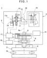
- a surveying instrument 1 is, for instance, a laser scanner.
- the surveying instrument 1 is constituted of a leveling module 2 mounted on a tripod (not shown) and a surveying instrument main body 3 mounted on the leveling module 2.
- the leveling module 2 has leveling screws 10, and the surveying instrument main body 3 is leveled up by the leveling screws 10.
- the surveying instrument main body 3 includes a fixing unit 4, a frame unit 5, a horizontal rotation shaft 6, a horizontal rotation bearing 7, a horizontal rotation motor 8 as a horizontal rotation driving module, a horizontal angle encoder 9 as a horizontal angle detector, a vertical rotation shaft 11, a vertical rotation bearing 12, a vertical rotation motor 13 as a vertical rotation driving module, a vertical angle encoder 14 as a vertical angle detector, a scanning mirror 15 which is a vertical rotation module, an operation panel 16 which serves as both an operation module and a display module, an arithmetic control module 17, a storage module 18, a distance measuring unit 19 and others.
- the arithmetic control module 17 a CPU specialized for this instrument or a general-purpose CPU is used.
- the horizontal rotation bearing 7 is fixed to the fixing unit 4.
- the horizontal rotation shaft 6 has a vertical axis 6a, and the horizontal rotation shaft 6 is rotatably supported by the horizontal rotation bearing 7. Further, the frame unit 5 is supported by the horizontal rotation shaft 6, and the frame unit 5 integrally rotates with the horizontal rotation shaft 6 in the horizontal direction.
- the horizontal rotation motor 8 is provided between the horizontal rotation bearing 7 and the frame unit 5, and the horizontal rotation motor 8 is controlled by the arithmetic control module 17.
- the arithmetic control module 17 rotates the frame unit 5 around the axis 6a by the horizontal rotation motor 8.
- a relative rotation angle of the frame unit 5 with respect to the fixing unit 4 is detected by the horizontal angle encoder 9.
- a detection signal from the horizontal angle encoder 9 is input to the arithmetic control module 17, and the horizontal angle data is calculated by the arithmetic control module 17.
- the arithmetic control module 17 performs the feedback control of the horizontal rotation motor 8 based on the horizontal angle data.
- the vertical rotation shaft 11 having a horizontal axis 11a is provided.
- the vertical rotation shaft 11 can rotate via the vertical rotation bearing 12. It is to be noted that an intersection of the axis 6a and the axis 11a is a projecting position for a distance measuring light, and the intersection is an origin of a coordinate system of the surveying instrument main body 3.
- a recess portion 22 is formed in the frame unit 5.
- One end portion of the vertical rotation shaft 11 extends to the inside of the recess portion 22.
- the scanning mirror 15 is fixed to the one end portion, and the scanning mirror 15 is accommodated in the recess portion 22.
- the vertical angle encoder 14 is provided at the other end portion of the vertical rotation shaft 11.
- the vertical rotation motor 13 is provided on the vertical rotation shaft 11, and the vertical rotation motor 13 is controlled by the arithmetic control module 17.
- the arithmetic control module 17 rotates the vertical rotation shaft 11 by the vertical rotation motor 13. Further, and the scanning mirror 15 is rotated around the axis 11a.
- a rotation angle of the scanning mirror 15 is detected by the vertical angle encoder 14, and a detection signal is input to the arithmetic control module 17.
- the arithmetic control module 17 calculates the vertical angle data of the scanning mirror 15 based on the detection signal, and performs the feedback control of the vertical rotation motor 13 based on the vertical angle data.
- the horizontal angle data and the vertical angle data calculated by the arithmetic control module 17, and the measurement results are stored in the storage module 18.
- various types of storage devices are used. These storage devices include: an HDD as a magnetic storage device, a CD or DVD as an optical storage device, a memory card and a USB memory as a semiconductor storage device, and other storage devices.
- the storage module 18 may be attachable to and detachable from the frame unit 5. Alternatively, the storage module 18 may enable transmitting the data to an external storage device or an external data processing device via a not shown communicating means.
- various types of programs are used. These programs include: a sequence program for controlling a distance measuring operation, a calculation program for calculating a distance by the distance measuring operation, a calculation program for calculating an angle based on the horizontal angle data and the vertical angle data, a calculation program for calculating three-dimensional coordinates of a desired measuring point based on a distance and an angle, and other programs. Further, when the various types of programs stored in the storage module 18 are executed by the arithmetic control module 17, various types of processing are performed.
- the operation panel 16 is, for instance, a touch panel.
- the operation panel 16 serves as both an operation module which performs, for instance, changing distance measurement instructions or measurement conditions such as a measuring point interval and a display module which displays distance measurement results, images and the like.
- the distance measuring unit 19 has a distance measuring light projecting module 23 and a distance measuring light receiving module 24. It is to be noted that, the distance measuring light projecting module 23 and the distance measuring light receiving module 24 configure a distance measuring unit.
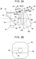
- the distance measuring light projecting module 23 has a distance measuring optical axis 25. Further, the distance measuring light projecting module 23 has a light emitter 26 such as a laser diode (LD), a collimator lens 27, a pinhole plate 28 as a spread angle adjusting member, and a reflecting prism 29 provided on the distance measuring optical axis 25 sequentially from a light emission side. Further, the scanning mirror 15 is provided on a reflected optical axis of the reflecting prism 29. Further, a window unit 31 which is formed of a transparent material and integrally rotates with the scanning mirror 15 is provided on a reflected optical axis of the scanning mirror 15. It is to be noted that the window unit 31 is provided in FIG.2 , but the window unit 31 may be omitted.
- LD laser diode
- the pinhole plate 28 is, for instance, a black plate material having a pinhole 33 drilled in a central portion.
- the pinhole plate 28 is insertable into or removable from the distance measuring optical axis 25 via a driving mechanism 34, for instance, a solenoid.
- a driving mechanism 34 for instance, a solenoid.
- the center of the pinhole 33 is placed on the distance measuring optical axis 25.
- the pinhole plate 28 is inserted onto the distance measuring optical axis 25. Further, in case of performing the non-prism measurement, which the object is other than the prism, the pinhole plate 28 is removed from the distance measuring optical axis 25.
- the distance measuring light 32 is decreased the light amount by the pinhole plate 28 and projected from the pinhole 33 while diverging (diameter-expanding) at a predetermined spread angle by a diffraction effect.
- a diameter of the pinhole 33 is set in such a manner that the spread angle ⁇ which is expanded by the diffraction is, for instance, 6 minutes.
- the diameter of the pinhole 33 is appropriately set in the range of 2 to 20 minutes.
- the pinhole plate 28 is provided between the collimator lens 27 and the reflecting prism 29.
- the pinhole plate 28 may be provided between the light emitter 26 and the collimator lens 27.
- the reflecting prism 29 is formed by joining two trapezoidal prisms.
- the reflecting prism 29 has a rectangular parallelepiped shape with the two prisms being joined.
- An incidence surface of the distance measuring light 32 is orthogonal to the distance measuring optical axis 25, and a joined surface 35 of the reflecting prism 29 tilts at a predetermined angle with respect to the distance measuring optical axis 25.
- a projecting surface of the reflecting prism 29 is configured in such a manner that the distance measuring optical axis 25 reflected on the joined surface 35 enters while slightly tilting at, for instance, approximately 2.5°. That is, the distance measuring light 32 enters the reflecting prism 29 at a slight tilt with respect to the projecting surface of the reflecting prism 29.
- the projecting surface of the reflecting prism 29 prevents the distance measuring light 32 internally-reflected by the projecting surface from being received by a photodetector 36 (to be described later). It is to be noted that a tilt angle of the joined surface 35 is an angle causing the deflection (the reflection) of the distance measuring optical axis 25 in such a manner that the distance measuring optical axis 25 coincides with a light receiving optical axis 37 (to be described later) and the axis 11a.
- the tilt angle of the joined surface 35 may be set to 45°, and the distance measuring light 32 may enter the reflecting prism 29 with the distance measuring optical axis 25 being tilt with respect to the incidence surface of the reflecting prism 29 in such a manner that the distance measuring optical axis 25 coincides with the light receiving optical axis 37 and the axis 11a.
- a beam splitter film 38 is formed at a central portion of the joined surface 35, and an antireflective film 39 is formed on entire front surface and back surface of the reflecting prism 29.
- the beam splitter film 38 has an elliptic shape in conformity with a light flux of the distance measuring light 32. Further, a size of the beam splitter film 38 is equivalent to or slightly larger than a light flux diameter of the distance measuring light 32 diverged by the pinhole 33. Further, for instance, the beam splitter film 38 has optical characteristics to reflect a light which is approximately 80% and transmit through a light which is approximately 20%.
- a ratio of a reflectance and a transmittance in the beam splitter film 38 is appropriately set in correspondence with applications or a distance to the object. For instance, in a case where the distance to the object is close, it is desirable to select the reflectance and the transmittance of the beam splitter film 38 from the range of the 50% to 70% reflectance and the 30% to 50% transmittance. Further, in a case where the distance to the object is far, it is desirable to select the reflectance and the transmittance of the beam splitter film 38 from the range of the 70% to 90% reflectance and the 10% to 30% transmittance.
- the distance measuring light receiving module 24 has the light receiving optical axis 37. Further, the distance measuring light receiving module 24 has the photodetector 36, a light amount adjusting plate 41, and a receiving prism 42 provided on the light receiving optical axis 37 sequentially from a light reception side, and has a light receiving lens 43 with a predetermined NA (Numerical Aperture) provided on the light receiving optical axis 37 reflected by the receiving prism 42.
- NA Numerical Aperture
- the light amount adjusting plate 41, the receiving prism 42, the light receiving lens 43, the reflecting prism 29, and the like configure a light receiving optical system 44.
- the light receiving optical axis 37 and the light receiving optical axis 37 reflected by the receiving prism 42 are generically referred to as the light receiving optical axis 37.
- the distance measuring unit 19 is controlled by the arithmetic control module 17.
- the pulsed distance measuring light 32 is projected onto the distance measuring optical axis 25 from the light emitter 26, then the distance measuring light 32 is turned to a parallel light flux by the collimator lens 27.
- the pinhole plate 28 since the pinhole plate 28 blocks lights other than the distance measuring light 32 which passes through the pinhole 33, a total light amount of the distance measuring light 32 is reduced, Furthermore, the distance measuring light 32 is projected at a predetermined spread angle due to the diffraction effect when it passes through the pinhole 33.
- the distance measuring light 32 which has passed through the pinhole 33 enters an incidence surface of the reflecting prism 29 at a right angle, and the distance measuring light 32 is transmitted through the reflecting prism 29 and reflected on the joined surface 35 (the beam splitter film 38) in such a manner that the distance measuring optical axis 25 becomes coaxial with the light receiving optical axis 37 and the axis 11a.
- the distance measuring light 32 projected from the reflecting prism 29 is deflected at a right angle by the scanning mirror 15 and irradiated to the object via the window unit 31.
- the distance measuring light 32 becomes orthogonal to the axis 11a, and the distance measuring light 32 is rotated (scanned) within a plane including the axis 6a.
- the distance measuring light 32 reflected by the object (hereinafter a reflected distance measuring light 45) is reflected at a right angle by the scanning mirror 15, and the reflected distance measuring light 45 is received by the photodetector 36 through the light receiving optical system 44.
- the photodetector 36 is, for instance, an avalanche photodiode (APD) or an equivalent photoelectric conversion element.
- an internal reference light optical system (to be described later) is provided in the distance measuring unit 19.
- the distance measuring unit 19 enables the further accurate distance measurement.
- the frame unit 5 and the scanning mirror 15 are rotated at a constant speed, respectively.
- a two-dimensional scan by the distance measuring light 32 is performed by the cooperation between the vertical rotation of the scanning mirror 15 and the horizontal rotation of the frame unit 5.
- the distance measurement data (a slope distance) is acquired by the distance measurement for each pulsed light, by detecting a vertical angle and a horizontal angle for each pulsed light by the vertical angle encoder 14 and the horizontal angle encoder 9, the arithmetic control module 17 enables calculating the vertical angle data and the horizontal angle data.
- Three-dimensional coordinates of the object and the three-dimensional point cloud data corresponding to the object can be acquired based on the vertical angle data, the horizontal angle data, and the distance measurement data.
- the transmittance of the light amount adjusting plate 41 is appropriately set in correspondence with a type of the object or a distance to the object.
- the distance measuring light 32 reflected on the beam splitter film 38 is transmitted at a slight tilt with respect to the projecting surface of the reflecting prism 29 and irradiated to the object, for instance, a prism having the retroreflective property via the scanning mirror 15.
- the reflected distance measuring light 45 which has been transmitted through the reflecting prism 29 and has entered the light receiving optical system 44 is refracted in a process of being transmitted through the light receiving lens 43 and the first surface 42a.
- the reflected distance measuring light 45 is internally-reflected sequentially by the second surface 42b and the first surface 42a in the receiving prism 42, and enters the third surface 42c. Further, the reflected distance measuring light 45 is reflected on the third surface 42c toward the fourth surface 42d, that is, in a direction crossing the reflected distance measuring light 45 which has entered from the first surface 42a.
- the reflected distance measuring light 45 transmitted through the fourth surface 42d is received by the photodetector 36 while being decreased the light amount in a process of being transmitted through the light amount adjusting plate 41.
- the arithmetic control module 17 calculates three-dimensional coordinates of the prism based on a distance measurement result of the distance measuring unit 19 and detection results of the horizontal angle encoder 9 and the vertical angle encoder 14.
- the pinhole plate 28 insertable and/or removable with respect to the distance measuring optical axis 25 is provided, and the dimming of the distance measuring light 32 and the expansion of the spread angle are enabled via the pinhole 33 of the pinhole plate 28.
- the prism measurement is performed using the distance measuring light 32 with a large light amount, a received light amount of the reflected distance measuring light 45 becomes excessive, and the photodetector 36 is saturated.
- the projecting surface of the reflecting prism 29 slightly tilts with respect to the distance measuring optical axis 25 deflected by the beam splitter film 38, it is possible to prevent the distance measuring light 32 internally reflected on the projecting surface is received by the photodetector 36, which reduces measurement errors.
- the receiving prism 42 is provided and the reflected distance measuring light 45 is internally reflected in the receiving prism 42 more than once, it is possible to be shorten an optical path length in a direction of the axis 11a (a left-and-right direction with respect to a plane of paper), downsize an optical system of the distance measuring unit 19, and reduce a weight of the surveying instrument 1.
- FIG.4 a description will be given on a second embodiment of the present invention. It is to be noted that, in FIG.4 , the same components as shown in FIG.2A are referred by the same symbols, and detailed description thereof will be omitted.
- the distance measuring optical axis 25 is configured to coincide with a light receiving optical axis 37 and an axis 11a. That is, in the second embodiment, a reflecting mirror 52 which deflects (reflects) the distance measuring optical axis 25 at a right angle is provided between a pinhole plate 28 and a reflecting prism 29.
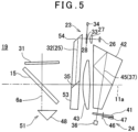
- FIG.5 a description will be given on a third embodiment of the present invention. It is to be noted that, in FIG.5 , the same components as shown in FIG.2A are referred by the same symbols, and detailed description thereof will be omitted.
- the third embodiment is configured to coincide a distance measuring optical axis 25 with a light receiving optical axis 37 and an axis 11a, by deflecting the distance measuring optical axis 25 twice.
- a reflecting prism 53 is a trapezoidal prism with two prisms joined together.
- the reflecting prism 53 has a reflecting surface 54, the reflecting surface 54 reflects (deflects) a distance measuring light 32 which entered at a right angle with respect to the reflecting prism 53 toward a joined surface 35.
- the distance measuring light 32 reflected on the reflecting surface 54 is deflected by a beam splitter film 38 on the joined surface 35 in such a manner that the distance measuring optical axis 25 coincides with a light receiving optical axis 37 and an axis 11a. Processes after incidence upon the beam splitter film 38 are the same as the processes in the first embodiment.
- the reflecting prism 53 has the reflecting surface 54 which deflects a distance measuring optical axis 25 toward the beam splitter film 38. Therefore, it is possible to be shorten an optical path length in a direction of an axis 6a (an up-and-down direction with respect to a plane of paper, see FIG.1 ) and downsize an optical system of a distance measuring unit 19.
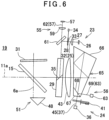
- the tracking light projecting module 55 has a tracking optical axis 57. Further, the tracking light projecting module 55 has a tracking light emitter 58, a collimator lens 59, a dichroic mirror 61, and a reflecting prism 29 sequentially provided on the tracking optical axis 57 from a light emission side. It is to be noted, in the present embodiment, the tracking optical axis 57 and the tracking optical axis 57 reflected by the reflecting prism 29 are generically referred to as the tracking optical axis 57. Further, a distance measuring light projecting module 23, that is, a light emitter 26, a collimator lens 27, and a pinhole plate 28 are provided on a reflection side of the dichroic mirror 61.
- the tracking light emitter 58 is, for instance, a laser diode (LD), and configured to project a tracking light 62 having a near-infrared wavelength different from a wavelength of a distance measuring light 32. Further, the dichroic mirror 61 is configured to transmit through the tracking light 62 and reflect the distance measuring light 32.
- LD laser diode
- the dichroic mirror 61 is provided on a common optical path of the distance measuring light 32 and the tracking light 62 (an intersecting position of a distance measuring optical axis 25 and the tracking optical axis 57), and deflects (reflects) the distance measuring optical axis 25 in such a manner that the distance measuring optical axis 25 coincides with the tracking optical axis 57. Therefore, the distance measuring light 32 and the tracking light 62 are coaxially irradiated toward an object.
- the tracking light receiving module 56 has a tracking light receiving optical axis 63. Further, the tracking light receiving module 56 has a tracking photodetector 64, a receiving prism 65, and a light receiving lens 43 sequentially provided on the tracking light receiving optical axis 62 from a light reception side.
- the receiving prism 65 has a configuration in which a first prism 66 which is a quadrangular prism having a predetermined refractive index and a second prism 67 which is triangular prism having a predetermined refractive index are joined and integrated with each other. In an integrated state, the receiving prism 65 has the same outer shape as the outer shape of the receiving prism 42 in the first embodiment.
- a dichroic filter film is provided on a joined surface 68 of the first prism 66 and the second prism 67, and the joined surface 68 is configured to transmit through a reflected distance measuring light 45 and reflect the tracking light 62 (a reflected tracking light 69) reflected on an object.
- the joined surface 68 is a separating surface for separating the reflected distance measuring light 45 (a light receiving optical axis 37) and the reflected tracking light 69 (the tracking light receiving optical axis 63) from each other.
- a first surface, a second surface, and a third surface in the receiving prism 65 have the same configurations as the configurations of the first surface 42a, the second surface 42b, and the third surface 42c of the receiving prism 42 in the first embodiment.
- a light amount adjusting plate 41 and a photodetector 36 are provided on a transmission side of the joined surface 68, and the tracking photodetector 64 is provided on a reflection side of the joined surface 68. That is, the joined surface 68 is placed on a common optical path of the reflected distance measuring light 45 and the reflected tracking light 69 (an intersecting position of the light receiving optical axis 37 and the tracking light receiving optical axis 63), and separates the reflected distance measuring light 45 and the reflected tracking light 69 from each other which have coaxially entered the receiving prism 65.
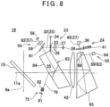
- a laser pointer light projecting module 71 and an image pickup module 72 are coaxially provided.
- the short-pass filter plate 78 has optical characteristics to transmit through a visible light and reflect a distance measuring light 32 (a reflected distance measuring light 45) and a tracking light 62 (a reflected tracking light 69). Further, the short-pass filter plate 78 deflects a distance measuring optical axis 25 and a tracking optical axis 57 in such a manner that the distance measuring optical axis 25 and the tracking optical axis 57 become coaxial with a laser pointer optical axis 74 transmitted through the short-pass filter plate 78. Further, the short-pass filter plate 78 separates the image pickup optical axis 79 from the light receiving optical axis 37 and a tracking light receiving optical axis 63. That is, the short-pass filter plate 78 is arranged on a common optical path of the distance measuring light 32 (the tracking light 62) and a laser pointer light.
- the image pickup module 72 has an image pickup element 81, a light receiving lens group 82, the beam splitter 76, the mirror 77, and the short-pass filter plate 78 provided on an optical axis of a background light received by the image pickup element 81 (the image pickup optical axis 79).
- a reflecting prism 83 tilts at approximately 35° with respect to an axis 11a, and a long-pass filter surface 84 having a long-pass filter provided is formed on a projecting surface of the reflecting prism 83 (a left surface with respect to a plane of paper). Further, a lower portion of the reflecting prism 83 is formed a chamfered portion.
Landscapes
- Physics & Mathematics (AREA)
- General Physics & Mathematics (AREA)
- Engineering & Computer Science (AREA)
- Radar, Positioning & Navigation (AREA)
- Remote Sensing (AREA)
- Electromagnetism (AREA)
- Optical Radar Systems And Details Thereof (AREA)
- Measurement Of Optical Distance (AREA)
Claims (2)
- Vermessungsinstrument, umfassend: ein Entfernungsmesslichtprojektionsmodul (23), das konfiguriert ist, ein Entfernungsmesslicht (32) auf ein Objekt zu projizieren, ein Entfernungsmesslichtempfangsmodul (24) mit einem Photodetektor (36), der konfiguriert ist, ein von dem Objekt reflektiertes Entfernungsmesslicht (45) zu empfangen, und ein arithmetisches Steuermodul (17), das konfiguriert ist, das Entfernungsmesslichtprojektionsmodul zu steuern und eine Entfernung zu dem Objekt auf Grundlage eines Lichtempfangsergebnisses des reflektierten Entfernungsmesslichts in Bezug auf den Photodetektor zu berechnen, wobei das Entfernungsmesslichtprojektionsmodul eine Lochblendenplatte (28) aufweist, die in Bezug auf eine optische Achse (25) des Entfernungsmesslichts einsetzbar oder entnehmbar ist, eine Lochblende (33) mit einem vorbestimmten Durchmesser in der Lochblendenplatte ausgebildet ist, und eine Lichtmenge und ein Streuwinkel des Entfernungsmesslichts auf Grundlage des Einsetzens oder Entfernens der Lochblendenplatte veränderbar sind, dadurch gekennzeichnet, dass das Entfernungsmesslichtprojektionsmodul (23) ein reflektierendes Prisma (29, 53, 83) mit zwei miteinander verbundenen Prismen aufweist, ein Strahlteilerfilm (38) mit einem vorbestimmten Reflexionsgrad und Transmissionsgrad auf einer gemeinsamen Oberfläche (35) des reflektierenden Prismas ausgebildet ist, und das reflektierende Prisma konfiguriert ist, die optische Achse (25) des Entfernungsmesslichts (32) über den Strahlteilerfilm so abzulenken, dass sie mit einer optischen Achse (37) des reflektierten Entfernungsmesslichts (45) zusammenfällt, wobei das reflektierende Prisma in Bezug auf die optische Achse des reflektierten Entfernungsmesslichts geneigt ist, sodass das Entfernungsmesslicht, das von dem Strahlteilerfilm reflektiert wird, mit einer leichten Neigung durch eine Projektionsfläche des reflektierenden Prismas hindurchtritt.
- Vermessungsinstrument nach Anspruch 1, wobei eine Langpassfilterfläche (84), die konfiguriert ist, das Entfernungsmesslicht (32), das ein Infrarotlicht oder ein Nahinfrarotlicht ist, durchzulassen und sichtbares Licht reflektiert, auf der Projektionsfläche ausgebildet ist und ein Bildaufnahmemodul (72) auf einer reflektierten optischen Achse (79) der Langpassfilterfläche vorgesehen ist.
Applications Claiming Priority (1)
| Application Number | Priority Date | Filing Date | Title |
|---|---|---|---|
| JP2022031615A JP7813609B2 (ja) | 2022-03-02 | 2022-03-02 | 測量装置 |
Publications (3)
| Publication Number | Publication Date |
|---|---|
| EP4239286A2 EP4239286A2 (de) | 2023-09-06 |
| EP4239286A3 EP4239286A3 (de) | 2023-12-06 |
| EP4239286B1 true EP4239286B1 (de) | 2025-07-09 |
Family
ID=85415210
Family Applications (1)
| Application Number | Title | Priority Date | Filing Date |
|---|---|---|---|
| EP23159404.5A Active EP4239286B1 (de) | 2022-03-02 | 2023-03-01 | Vermessungsinstrument |
Country Status (4)
| Country | Link |
|---|---|
| US (1) | US20230280161A1 (de) |
| EP (1) | EP4239286B1 (de) |
| JP (1) | JP7813609B2 (de) |
| CN (1) | CN116697886A (de) |
Families Citing this family (2)
| Publication number | Priority date | Publication date | Assignee | Title |
|---|---|---|---|---|
| JP2023149250A (ja) * | 2022-03-30 | 2023-10-13 | 株式会社トプコン | 測量機 |
| JP2025006809A (ja) * | 2023-06-30 | 2025-01-17 | 株式会社トプコン | 測量装置 |
Family Cites Families (9)
| Publication number | Priority date | Publication date | Assignee | Title |
|---|---|---|---|---|
| US4569591A (en) * | 1983-03-07 | 1986-02-11 | Texas Instruments Incorporated | Laser boresight alignment mechanism for integrated laser/FLIR rangefinder |
| JP4491661B2 (ja) * | 1999-11-17 | 2010-06-30 | 株式会社トプコン | 光波距離計 |
| US6945657B2 (en) * | 2000-10-19 | 2005-09-20 | Pentax Corporation | Surveying instrument |
| JP6253973B2 (ja) * | 2013-12-27 | 2017-12-27 | 株式会社トプコン | 測量装置 |
| JP6557548B2 (ja) * | 2015-08-12 | 2019-08-07 | 株式会社トプコン | 自動測量機 |
| EP3489714A1 (de) * | 2017-11-28 | 2019-05-29 | Hexagon Technology Center GmbH | Optischer distanzmesser mit schaltbarer empfangsapertur |
| JP7360298B2 (ja) * | 2019-10-23 | 2023-10-12 | 株式会社トプコン | 測量装置 |
| EP3835722A1 (de) * | 2019-12-13 | 2021-06-16 | Leica Geosystems AG | Einspiegelungsvorrichtung |
| JP7421438B2 (ja) * | 2020-07-27 | 2024-01-24 | 株式会社トプコン | 測量装置 |
-
2022
- 2022-03-02 JP JP2022031615A patent/JP7813609B2/ja active Active
-
2023
- 2023-02-28 US US18/115,431 patent/US20230280161A1/en active Pending
- 2023-03-01 EP EP23159404.5A patent/EP4239286B1/de active Active
- 2023-03-02 CN CN202310201354.1A patent/CN116697886A/zh active Pending
Also Published As
| Publication number | Publication date |
|---|---|
| EP4239286A3 (de) | 2023-12-06 |
| CN116697886A (zh) | 2023-09-05 |
| JP7813609B2 (ja) | 2026-02-13 |
| US20230280161A1 (en) | 2023-09-07 |
| EP4239286A2 (de) | 2023-09-06 |
| JP2023127742A (ja) | 2023-09-14 |
Similar Documents
| Publication | Publication Date | Title |
|---|---|---|
| US11536567B2 (en) | Surveying instrument | |
| EP1411371B1 (de) | Vermessungs- und Positions-Vorrichtung mit aufgefächertem Lichtstrahl | |
| US11629959B2 (en) | Surveying instrument | |
| US11668567B2 (en) | Surveying instrument | |
| EP3812700B1 (de) | Vermessungsinstrument | |
| US12372354B2 (en) | Surveying instrument | |
| JP2016151423A (ja) | 姿勢検出装置及びデータ取得装置 | |
| EP4239286B1 (de) | Vermessungsinstrument | |
| US20210285765A1 (en) | Surveying Instrument | |
| EP3957951B1 (de) | Vermessungsinstrument | |
| US20230033565A1 (en) | Surveying instrument | |
| US20230280160A1 (en) | Surveying instrument | |
| WO2024172113A1 (ja) | 測量装置 | |
| EP4160145A1 (de) | Vermessungsinstrument | |
| JP2021117013A (ja) | 測量装置 | |
| EP4692725A1 (de) | Vermessungsvorrichtung | |
| WO2025022967A1 (ja) | 測量装置 | |
| WO2024172114A1 (ja) | 測量装置 | |
| WO2024195540A1 (ja) | 測量装置 | |
| WO2025005077A1 (ja) | 測量装置 |
Legal Events
| Date | Code | Title | Description |
|---|---|---|---|
| PUAI | Public reference made under article 153(3) epc to a published international application that has entered the european phase |
Free format text: ORIGINAL CODE: 0009012 |
|
| STAA | Information on the status of an ep patent application or granted ep patent |
Free format text: STATUS: REQUEST FOR EXAMINATION WAS MADE |
|
| 17P | Request for examination filed |
Effective date: 20230301 |
|
| AK | Designated contracting states |
Kind code of ref document: A2 Designated state(s): AL AT BE BG CH CY CZ DE DK EE ES FI FR GB GR HR HU IE IS IT LI LT LU LV MC ME MK MT NL NO PL PT RO RS SE SI SK SM TR |
|
| PUAL | Search report despatched |
Free format text: ORIGINAL CODE: 0009013 |
|
| AK | Designated contracting states |
Kind code of ref document: A3 Designated state(s): AL AT BE BG CH CY CZ DE DK EE ES FI FR GB GR HR HU IE IS IT LI LT LU LV MC ME MK MT NL NO PL PT RO RS SE SI SK SM TR |
|
| RIC1 | Information provided on ipc code assigned before grant |
Ipc: G01C 3/08 20060101ALI20231027BHEP Ipc: G01C 15/00 20060101AFI20231027BHEP |
|
| RBV | Designated contracting states (corrected) |
Designated state(s): AL AT BE BG CH CY CZ DE DK EE ES FI FR GB GR HR HU IE IS IT LI LT LU LV MC ME MK MT NL NO PL PT RO RS SE SI SK SM TR |
|
| GRAP | Despatch of communication of intention to grant a patent |
Free format text: ORIGINAL CODE: EPIDOSNIGR1 |
|
| STAA | Information on the status of an ep patent application or granted ep patent |
Free format text: STATUS: GRANT OF PATENT IS INTENDED |
|
| INTG | Intention to grant announced |
Effective date: 20250226 |
|
| GRAS | Grant fee paid |
Free format text: ORIGINAL CODE: EPIDOSNIGR3 |
|
| GRAA | (expected) grant |
Free format text: ORIGINAL CODE: 0009210 |
|
| STAA | Information on the status of an ep patent application or granted ep patent |
Free format text: STATUS: THE PATENT HAS BEEN GRANTED |
|
| AK | Designated contracting states |
Kind code of ref document: B1 Designated state(s): AL AT BE BG CH CY CZ DE DK EE ES FI FR GB GR HR HU IE IS IT LI LT LU LV MC ME MK MT NL NO PL PT RO RS SE SI SK SM TR |
|
| REG | Reference to a national code |
Ref country code: GB Ref legal event code: FG4D |
|
| REG | Reference to a national code |
Ref country code: CH Ref legal event code: EP |
|
| REG | Reference to a national code |
Ref country code: IE Ref legal event code: FG4D |
|
| REG | Reference to a national code |
Ref country code: DE Ref legal event code: R096 Ref document number: 602023004599 Country of ref document: DE |
|
| REG | Reference to a national code |
Ref country code: NL Ref legal event code: MP Effective date: 20250709 |
|
| PG25 | Lapsed in a contracting state [announced via postgrant information from national office to epo] |
Ref country code: PT Free format text: LAPSE BECAUSE OF FAILURE TO SUBMIT A TRANSLATION OF THE DESCRIPTION OR TO PAY THE FEE WITHIN THE PRESCRIBED TIME-LIMIT Effective date: 20251110 |
|
| PG25 | Lapsed in a contracting state [announced via postgrant information from national office to epo] |
Ref country code: NL Free format text: LAPSE BECAUSE OF FAILURE TO SUBMIT A TRANSLATION OF THE DESCRIPTION OR TO PAY THE FEE WITHIN THE PRESCRIBED TIME-LIMIT Effective date: 20250709 |
|
| REG | Reference to a national code |
Ref country code: AT Ref legal event code: MK05 Ref document number: 1812158 Country of ref document: AT Kind code of ref document: T Effective date: 20250709 |
|
| PG25 | Lapsed in a contracting state [announced via postgrant information from national office to epo] |
Ref country code: IS Free format text: LAPSE BECAUSE OF FAILURE TO SUBMIT A TRANSLATION OF THE DESCRIPTION OR TO PAY THE FEE WITHIN THE PRESCRIBED TIME-LIMIT Effective date: 20251109 |
|
| PG25 | Lapsed in a contracting state [announced via postgrant information from national office to epo] |
Ref country code: NO Free format text: LAPSE BECAUSE OF FAILURE TO SUBMIT A TRANSLATION OF THE DESCRIPTION OR TO PAY THE FEE WITHIN THE PRESCRIBED TIME-LIMIT Effective date: 20251009 |
|
| REG | Reference to a national code |
Ref country code: LT Ref legal event code: MG9D |
|
| PG25 | Lapsed in a contracting state [announced via postgrant information from national office to epo] |
Ref country code: AT Free format text: LAPSE BECAUSE OF FAILURE TO SUBMIT A TRANSLATION OF THE DESCRIPTION OR TO PAY THE FEE WITHIN THE PRESCRIBED TIME-LIMIT Effective date: 20250709 |
|
| PG25 | Lapsed in a contracting state [announced via postgrant information from national office to epo] |
Ref country code: FI Free format text: LAPSE BECAUSE OF FAILURE TO SUBMIT A TRANSLATION OF THE DESCRIPTION OR TO PAY THE FEE WITHIN THE PRESCRIBED TIME-LIMIT Effective date: 20250709 |
|
| PG25 | Lapsed in a contracting state [announced via postgrant information from national office to epo] |
Ref country code: HR Free format text: LAPSE BECAUSE OF FAILURE TO SUBMIT A TRANSLATION OF THE DESCRIPTION OR TO PAY THE FEE WITHIN THE PRESCRIBED TIME-LIMIT Effective date: 20250709 |
|
| PG25 | Lapsed in a contracting state [announced via postgrant information from national office to epo] |
Ref country code: GR Free format text: LAPSE BECAUSE OF FAILURE TO SUBMIT A TRANSLATION OF THE DESCRIPTION OR TO PAY THE FEE WITHIN THE PRESCRIBED TIME-LIMIT Effective date: 20251010 |
|
| PG25 | Lapsed in a contracting state [announced via postgrant information from national office to epo] |
Ref country code: SE Free format text: LAPSE BECAUSE OF FAILURE TO SUBMIT A TRANSLATION OF THE DESCRIPTION OR TO PAY THE FEE WITHIN THE PRESCRIBED TIME-LIMIT Effective date: 20250709 |
|
| PG25 | Lapsed in a contracting state [announced via postgrant information from national office to epo] |
Ref country code: LV Free format text: LAPSE BECAUSE OF FAILURE TO SUBMIT A TRANSLATION OF THE DESCRIPTION OR TO PAY THE FEE WITHIN THE PRESCRIBED TIME-LIMIT Effective date: 20250709 |
|
| PG25 | Lapsed in a contracting state [announced via postgrant information from national office to epo] |
Ref country code: BG Free format text: LAPSE BECAUSE OF FAILURE TO SUBMIT A TRANSLATION OF THE DESCRIPTION OR TO PAY THE FEE WITHIN THE PRESCRIBED TIME-LIMIT Effective date: 20250709 Ref country code: PL Free format text: LAPSE BECAUSE OF FAILURE TO SUBMIT A TRANSLATION OF THE DESCRIPTION OR TO PAY THE FEE WITHIN THE PRESCRIBED TIME-LIMIT Effective date: 20250709 |
|
| PG25 | Lapsed in a contracting state [announced via postgrant information from national office to epo] |
Ref country code: RS Free format text: LAPSE BECAUSE OF FAILURE TO SUBMIT A TRANSLATION OF THE DESCRIPTION OR TO PAY THE FEE WITHIN THE PRESCRIBED TIME-LIMIT Effective date: 20251009 |
|
| PG25 | Lapsed in a contracting state [announced via postgrant information from national office to epo] |
Ref country code: ES Free format text: LAPSE BECAUSE OF FAILURE TO SUBMIT A TRANSLATION OF THE DESCRIPTION OR TO PAY THE FEE WITHIN THE PRESCRIBED TIME-LIMIT Effective date: 20250709 |