EP4239264A1 - Porte de réfrigérateur ayant un ensemble d'isolation sous vide et son procédé de fabrication - Google Patents
Porte de réfrigérateur ayant un ensemble d'isolation sous vide et son procédé de fabrication Download PDFInfo
- Publication number
- EP4239264A1 EP4239264A1 EP21886969.1A EP21886969A EP4239264A1 EP 4239264 A1 EP4239264 A1 EP 4239264A1 EP 21886969 A EP21886969 A EP 21886969A EP 4239264 A1 EP4239264 A1 EP 4239264A1
- Authority
- EP
- European Patent Office
- Prior art keywords
- door
- door body
- vacuum insulation
- insulation assembly
- casing
- Prior art date
- Legal status (The legal status is an assumption and is not a legal conclusion. Google has not performed a legal analysis and makes no representation as to the accuracy of the status listed.)
- Pending
Links
- 238000009413 insulation Methods 0.000 title claims abstract description 144
- 238000000034 method Methods 0.000 title claims abstract description 31
- 238000004519 manufacturing process Methods 0.000 title claims abstract description 15
- 239000006260 foam Substances 0.000 claims abstract description 41
- 230000008878 coupling Effects 0.000 claims description 97
- 238000010168 coupling process Methods 0.000 claims description 97
- 238000005859 coupling reaction Methods 0.000 claims description 97
- 125000006850 spacer group Chemical group 0.000 claims description 71
- 238000003860 storage Methods 0.000 claims description 56
- 230000002093 peripheral effect Effects 0.000 claims description 24
- 239000011324 bead Substances 0.000 claims description 15
- 238000005187 foaming Methods 0.000 claims description 4
- 230000000149 penetrating effect Effects 0.000 claims description 2
- 238000007789 sealing Methods 0.000 claims 1
- 239000010408 film Substances 0.000 description 68
- 239000012212 insulator Substances 0.000 description 13
- 230000002265 prevention Effects 0.000 description 7
- 238000003466 welding Methods 0.000 description 7
- 230000015572 biosynthetic process Effects 0.000 description 5
- 230000000694 effects Effects 0.000 description 5
- 230000002452 interceptive effect Effects 0.000 description 4
- 239000000463 material Substances 0.000 description 4
- 238000005192 partition Methods 0.000 description 4
- 230000005540 biological transmission Effects 0.000 description 3
- 238000001816 cooling Methods 0.000 description 3
- 239000002390 adhesive tape Substances 0.000 description 2
- 229910052782 aluminium Inorganic materials 0.000 description 2
- XAGFODPZIPBFFR-UHFFFAOYSA-N aluminium Chemical compound [Al] XAGFODPZIPBFFR-UHFFFAOYSA-N 0.000 description 2
- 238000002347 injection Methods 0.000 description 2
- 239000007924 injection Substances 0.000 description 2
- 239000007769 metal material Substances 0.000 description 2
- 239000000243 solution Substances 0.000 description 2
- 229910000831 Steel Inorganic materials 0.000 description 1
- 239000000853 adhesive Substances 0.000 description 1
- 230000001070 adhesive effect Effects 0.000 description 1
- 229910045601 alloy Inorganic materials 0.000 description 1
- 239000000956 alloy Substances 0.000 description 1
- 230000015556 catabolic process Effects 0.000 description 1
- 238000005520 cutting process Methods 0.000 description 1
- 238000006731 degradation reaction Methods 0.000 description 1
- 239000000945 filler Substances 0.000 description 1
- 239000012530 fluid Substances 0.000 description 1
- 238000007710 freezing Methods 0.000 description 1
- 230000008014 freezing Effects 0.000 description 1
- 238000010438 heat treatment Methods 0.000 description 1
- 238000009434 installation Methods 0.000 description 1
- 230000005389 magnetism Effects 0.000 description 1
- 239000011104 metalized film Substances 0.000 description 1
- 229920002635 polyurethane Polymers 0.000 description 1
- 239000004814 polyurethane Substances 0.000 description 1
- 238000004080 punching Methods 0.000 description 1
- 239000011347 resin Substances 0.000 description 1
- 229920005989 resin Polymers 0.000 description 1
- 238000009751 slip forming Methods 0.000 description 1
- 239000010935 stainless steel Substances 0.000 description 1
- 229910001220 stainless steel Inorganic materials 0.000 description 1
- 239000010959 steel Substances 0.000 description 1
- 238000010792 warming Methods 0.000 description 1
Images


Classifications
-
- F—MECHANICAL ENGINEERING; LIGHTING; HEATING; WEAPONS; BLASTING
- F25—REFRIGERATION OR COOLING; COMBINED HEATING AND REFRIGERATION SYSTEMS; HEAT PUMP SYSTEMS; MANUFACTURE OR STORAGE OF ICE; LIQUEFACTION SOLIDIFICATION OF GASES
- F25D—REFRIGERATORS; COLD ROOMS; ICE-BOXES; COOLING OR FREEZING APPARATUS NOT OTHERWISE PROVIDED FOR
- F25D23/00—General constructional features
- F25D23/02—Doors; Covers
- F25D23/028—Details
-
- B—PERFORMING OPERATIONS; TRANSPORTING
- B29—WORKING OF PLASTICS; WORKING OF SUBSTANCES IN A PLASTIC STATE IN GENERAL
- B29C—SHAPING OR JOINING OF PLASTICS; SHAPING OF MATERIAL IN A PLASTIC STATE, NOT OTHERWISE PROVIDED FOR; AFTER-TREATMENT OF THE SHAPED PRODUCTS, e.g. REPAIRING
- B29C44/00—Shaping by internal pressure generated in the material, e.g. swelling or foaming ; Producing porous or cellular expanded plastics articles
- B29C44/02—Shaping by internal pressure generated in the material, e.g. swelling or foaming ; Producing porous or cellular expanded plastics articles for articles of definite length, i.e. discrete articles
- B29C44/12—Incorporating or moulding on preformed parts, e.g. inserts or reinforcements
- B29C44/18—Filling preformed cavities
-
- F—MECHANICAL ENGINEERING; LIGHTING; HEATING; WEAPONS; BLASTING
- F16—ENGINEERING ELEMENTS AND UNITS; GENERAL MEASURES FOR PRODUCING AND MAINTAINING EFFECTIVE FUNCTIONING OF MACHINES OR INSTALLATIONS; THERMAL INSULATION IN GENERAL
- F16L—PIPES; JOINTS OR FITTINGS FOR PIPES; SUPPORTS FOR PIPES, CABLES OR PROTECTIVE TUBING; MEANS FOR THERMAL INSULATION IN GENERAL
- F16L59/00—Thermal insulation in general
- F16L59/02—Shape or form of insulating materials, with or without coverings integral with the insulating materials
-
- F—MECHANICAL ENGINEERING; LIGHTING; HEATING; WEAPONS; BLASTING
- F25—REFRIGERATION OR COOLING; COMBINED HEATING AND REFRIGERATION SYSTEMS; HEAT PUMP SYSTEMS; MANUFACTURE OR STORAGE OF ICE; LIQUEFACTION SOLIDIFICATION OF GASES
- F25D—REFRIGERATORS; COLD ROOMS; ICE-BOXES; COOLING OR FREEZING APPARATUS NOT OTHERWISE PROVIDED FOR
- F25D23/00—General constructional features
- F25D23/02—Doors; Covers
-
- B—PERFORMING OPERATIONS; TRANSPORTING
- B29—WORKING OF PLASTICS; WORKING OF SUBSTANCES IN A PLASTIC STATE IN GENERAL
- B29L—INDEXING SCHEME ASSOCIATED WITH SUBCLASS B29C, RELATING TO PARTICULAR ARTICLES
- B29L2031/00—Other particular articles
-
- B—PERFORMING OPERATIONS; TRANSPORTING
- B29—WORKING OF PLASTICS; WORKING OF SUBSTANCES IN A PLASTIC STATE IN GENERAL
- B29L—INDEXING SCHEME ASSOCIATED WITH SUBCLASS B29C, RELATING TO PARTICULAR ARTICLES
- B29L2031/00—Other particular articles
- B29L2031/724—Doors
-
- B—PERFORMING OPERATIONS; TRANSPORTING
- B29—WORKING OF PLASTICS; WORKING OF SUBSTANCES IN A PLASTIC STATE IN GENERAL
- B29L—INDEXING SCHEME ASSOCIATED WITH SUBCLASS B29C, RELATING TO PARTICULAR ARTICLES
- B29L2031/00—Other particular articles
- B29L2031/762—Household appliances
- B29L2031/7622—Refrigerators
-
- F—MECHANICAL ENGINEERING; LIGHTING; HEATING; WEAPONS; BLASTING
- F25—REFRIGERATION OR COOLING; COMBINED HEATING AND REFRIGERATION SYSTEMS; HEAT PUMP SYSTEMS; MANUFACTURE OR STORAGE OF ICE; LIQUEFACTION SOLIDIFICATION OF GASES
- F25D—REFRIGERATORS; COLD ROOMS; ICE-BOXES; COOLING OR FREEZING APPARATUS NOT OTHERWISE PROVIDED FOR
- F25D2201/00—Insulation
- F25D2201/10—Insulation with respect to heat
- F25D2201/12—Insulation with respect to heat using an insulating packing material
- F25D2201/126—Insulation with respect to heat using an insulating packing material of cellular type
-
- F—MECHANICAL ENGINEERING; LIGHTING; HEATING; WEAPONS; BLASTING
- F25—REFRIGERATION OR COOLING; COMBINED HEATING AND REFRIGERATION SYSTEMS; HEAT PUMP SYSTEMS; MANUFACTURE OR STORAGE OF ICE; LIQUEFACTION SOLIDIFICATION OF GASES
- F25D—REFRIGERATORS; COLD ROOMS; ICE-BOXES; COOLING OR FREEZING APPARATUS NOT OTHERWISE PROVIDED FOR
- F25D2201/00—Insulation
- F25D2201/10—Insulation with respect to heat
- F25D2201/14—Insulation with respect to heat using subatmospheric pressure
-
- F—MECHANICAL ENGINEERING; LIGHTING; HEATING; WEAPONS; BLASTING
- F25—REFRIGERATION OR COOLING; COMBINED HEATING AND REFRIGERATION SYSTEMS; HEAT PUMP SYSTEMS; MANUFACTURE OR STORAGE OF ICE; LIQUEFACTION SOLIDIFICATION OF GASES
- F25D—REFRIGERATORS; COLD ROOMS; ICE-BOXES; COOLING OR FREEZING APPARATUS NOT OTHERWISE PROVIDED FOR
- F25D2323/00—General constructional features not provided for in other groups of this subclass
- F25D2323/02—Details of doors or covers not otherwise covered
- F25D2323/023—Door in door constructions
Definitions
- the present disclosure relates to a refrigerator door and, more particularly, to a refrigerator door having a vacuum insulation assembly therein and a method for manufacturing the same.
- a vacuum insulator maintains a vacuum inside a part to suppress heat transmission. Since the vacuum insulator can reduce heat transmission by convection and conduction, the vacuum insulator is applied to a warming apparatus and a cooling apparatus. Meanwhile, although an insulation method differs depending on whether the method is applied for cooling or freezing, it was common for the insulation method applied to a conventional refrigerator to provide a foaming polyurethane insulation wall with a thickness of more than about 30cm. However, the insulation wall has a problem for reducing an internal volume of the refrigerator.
- a welded portion constituting an edge of the vacuum insulator is likely to interfere with other parts in the small internal space of the refrigerator door, and when the welded portion interferes with other parts, the welded portion is open, and there is concern that a vacuum state of the vacuum insulator may be released.
- the refrigerator door may have a double structure and, for example, a main door and a sub door are provided doubly, and when the sub door is opened, a sub storage compartment provided by the main door may be used.
- a sub storage compartment provided by the main door may be used.
- the vacuum insulator is applied to the sub door, the thickness of the sub door becomes thin and the volume of the sub storage compartment can widen.
- a space through which cool air may be transmitted widens together with the sub storage compartment, and there is concern that dew formation occurs on a gasket installed between the two doors.
- a radiant heat shield film may be installed inside the vacuum insulator to block radiant heat.
- the radiant heat shield film may be moved inside the vacuum insulator. As described above, movement of the radiant heat shield film may cause generation of noise, and quality degradation of the refrigerator.
- the present disclosure has been made to solve the problems occurring in the related art as described above, and the present disclosure is intended to apply a vacuum insulation assembly inside a refrigerator door, and to prevent the vacuum insulation assembly from interfering with other parts inside the refrigerator door.
- Another objective of the present disclosure is to restrict a flow path of cool air to prevent dew formation on a gasket even when a vacuum insulation assembly is applied to a refrigerator door to widen a storage space of the door.
- Still another objective of the present disclosure is to fix a radiant heat shield film to prevent the radiant heat shield film constituting a vacuum insulation assembly from being moved in a process of opening and closing a refrigerator door.
- a first door body and a second door body of the present disclosure may be coupled to each other to form the exterior of a refrigerator door.
- a heat insulating space may be formed between a first door body and a second door body, and a vacuum insulation assembly may be installed inside the heat insulating space.
- a sealed vacuum chamber may be provided inside the vacuum insulation assembly, and at least a part of an edge of the vacuum insulation assembly may be surrounded by a foam filled part.
- the vacuum insulation assembly may be installed inside the refrigerator door, and since the vacuum insulation assembly has high insulation performance so that the vacuum insulation assembly may replace the existing foam filled part, and therefore, the thickness of the refrigerator door may be reduced.
- the vacuum insulation assembly may include a coupling part provided along the edge of the vacuum insulation assembly to maintain a vacuum in the vacuum chamber of the vacuum insulation assembly, and at least a part of the coupling part may be surrounded by the foam filled part while being spaced apart from a peripheral part inside the heat insulating space. Then, interference between the peripheral part inside the door and the coupling part may be prevented, and removal of a vacuum state of the vacuum insulation assembly likely generated by the interference between the parts may be prevented.
- the second door body may have a storage space formed in a direction of a storage compartment of the refrigerator, and a dyke part may protrude on a lower portion of the second door body forming a bottom of the storage space toward the storage compartment or the main door. At least a part of the dyke part may be overlapped with a frame of the refrigerator or the main door.
- the dyke part may restrict a cool air flow path generated between the two doors (main door-sub door), may divert cool air, and accordingly, dew formation generated when a gasket installed between the two doors is cooled may be prevented.
- An end of the dyke part may protrude in the direction of the storage compartment of the refrigerator more than the gasket provided between the second door body and the frame or the second door body and the main door. Accordingly, the dyke part may cover the frame or an upper portion of a portion where the dyke part meets the main door to block a leakage flow path.
- the dyke part may be provided to extend to a first plate of the second door body forming a side surface of the storage space. Then, the dyke part may block the entire leakage flow path between the sub door and the main door.
- the vacuum insulation assembly may include a first casing facing the first door body and a second casing coupled to the first casing to form the vacuum chamber between the first casing and the second casing.
- a radiant heat shield film may be installed in the vacuum chamber of the vacuum insulation assembly, and a pair of spacers may be respectively provided at the opposite sides of the radiant heat shield film. The pair of spacers may be assembled with each other through a coupling hole of the radiant heat shield film to allow the radiant heat shield film to be spaced apart from both of the first casing and the second casing.
- a coupling part may be formed in both of the first casing and the second casing so that the first casing and the second casing may be coupled to each other while being in close contact with each other along edges thereof.
- the coupling part may have a gap space between the coupling part and a peripheral part inside the heat insulating space. Therefore, the coupling part may be prevented from being brought into contact with the peripheral part inside the door, and removal of a vacuum state of the vacuum insulation assembly generated likely by interference between the parts may be prevented.
- the second door body may include the first plate forming a side surface of the storage space, and a second plate connected to the first plate to form a rear surface of the storage space.
- one end of the second door body extending from the first plate and located in the filling space filled with the foam filled part is spaced apart from the coupling part of the vacuum insulation assembly to have a first gap space between the coupling part and the end of the second door body, and (ii) a portion where the first plate and the second plate are connected to each other is spaced apart from the second casing of the vacuum insulation assembly to have a second gap space between the second casing and the portion.
- the two gap spaces may prevent the vacuum insulation assembly from interfering with other parts in the door.
- the spacers may include a first spacer from which a boss part protrudes to pass through the coupling hole, and a second spacer having an assembly groove into which an end of the boss part that has passed through the coupling hole is coupled.
- the boss part may have a shape with the width widening gradually toward a surface of the first spacer. The shape of the boss part may prevent the radiant heat shield film from being brought into contact with the surface of the first spacer.
- the radiant heat shield film may have a burring part bent along a rim of the coupling hole, and the burring part may extend in a longitudinal direction of the boss part to surround a surface of the boss part.
- the burring part may increase a contact area between the coupling hole and the boss part protruding on the spacer, and accordingly, may prevent the radiant heat shield film from being moved upward and downward between the pair of spacers.
- the second spacer may have a flange part protruding in a direction of the first spacer, and the assembly groove may be formed inside the flange part.
- an outer diameter of the flange part may be formed larger than an inner diameter of the coupling hole, so that the flange part may prevent the radiant heat shield film from being brought into contact with a surface of the second spacer.
- the radiant heat shield film may have a bead part protruding toward an inner surface of the first casing or an inner surface of the second casing.
- the bead part formed in the radiant heat shield film may reinforce the strength of the thin radiant heat shield film to further reduce noise generated when the radiant heat shield film is shaken.
- an exhaust port may be connected to the vacuum insulation assembly to connect the vacuum chamber to the external space, and an end of the exhaust port may be received inside the second door body or may be surrounded by the foam filled part.
- the refrigerator door having the vacuum insulation assembly and the method for manufacturing the same have the following effects.
- the vacuum insulation assembly may be installed inside the refrigerator door. Since the vacuum insulation assembly has high heat insulation performance, there is the effect that the vacuum insulation assembly can be substituted for the existing foam filled part and, therefore, there is the effect that the thickness of the refrigerator door can be reduced. Furthermore, as described above, as the thickness of the refrigerator door is reduced, the volume of the storage compartment for storing food increases relatively, which is an advantage.
- the vacuum insulation assembly may have the coupling part of which an edge portion is fixed by a welding method, etc. in order to maintain the vacuum chamber therein, and the coupling part may be installed not to interfere with other parts inside the refrigerator door. While the coupling part is surrounded with the foam filled part, a contact between a peripheral part inside the door and the coupling part can be prevented. Therefore, there is the effects that removal of the vacuum state of the vacuum insulation assembly likely generated by interference between the parts can be prevented, and eventually, the durability of the refrigerator door is improved.
- the dyke part may protrude on the sub door installed at the relatively outside portion in a direction in which the two doors are blocked from each other.
- the dyke part may restrict a cool air flow path formed between the two doors, or divert cool air. Accordingly, it is possible to prevent dew formation generated when the gasket installed between the two doors is cooled so that the quality of the refrigerator can be improved.
- the radiant heat shield film may be embedded inside the vacuum insulation assembly installed inside the refrigerator door, and the radiant heat shield film may be installed to be spaced apart from each of the pair of spacers. This structure can prevent the radiant heat shield film from hitting the inner surface of the vacuum insulation assembly, and reduce noise.
- the coupling hole for an assembly with the spacer is formed in the radiant heat shield film constituting the vacuum insulation assembly, and the burring part is bent on a rim of the coupling hole.
- the burring part widens a contact area with the boss part protruding on the spacer. Therefore, the radiant heat shield film can restrict raised and lowered movements with respect to the pair of spacers, and therefore, noise generated in the door opening and closing process can be significantly reduced.
- the bead part formed in the radiant heat shield film reinforces the strength of the thin radiant heat shield film to reduce noise generated when the radiant heat shield film is shaken.
- the vacuum insulation assembly in order to perform heat insulating of the internal space of the door, the vacuum insulation assembly is used and the foam filled part may be filled in a part of an edge without the vacuum insulation assembly. Therefore, since the amount of the foam filled part is significantly reduced, the manufacturing speed of the refrigerator door may increase, which is advantageous in mass production.
- the foam filled part serves to surround an edge portion of the vacuum insulation assembly naturally to fix the edge, so that even when a separate fixing device is not provided, the vacuum insulation assembly can be securely fixed without interference with a peripheral part.
- the present disclosure relates to a refrigerator door having a vacuum insulation assembly 50 (hereinbelow, which is referred to as "refrigerator door"), and the vacuum insulation assembly 50 is embedded in the refrigerator door so that insulation performance can be enhanced and the entire thickness of the refrigerator door can be reduced.
- the present disclosure may be applied to a general refrigerator door consisting of a single door, or may be applied to a double door of a door in door type.
- an application in which the present disclosure is applied to the double door will be described as example.
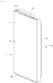
- FIGS. 1 and 2 views showing the refrigerator door having a double structure.
- a main door 100 is installed at a cabinet (not shown) of a refrigerator, and a sub door 1 may be installed outside the main door 100.
- the main door 100 and the sub door 1 are names given for convenience, and may be called as a first door and a second door or an inner door or an outer door.
- the main door 100 and the sub door 1 may be respectively installed to the cabinet, and may be rotated independently from each other. For example, when only the sub door 1 is rotated without rotating the main door 100, a storage space P provided between the sub door 1 and the main door 100 may be exposed.
- the storage space P may be partitioned with a basket 27 attached to an inner surface of the sub door 1, etc.
- the inner surface of the sub door 1 means a surface facing the inside space of the cabinet, among surfaces of a second door body 20, which will be described below.
- the storage compartment provided in the inside space of the cabinet is connected to the external space through the main door 100, but even when the sub door 1 is opened, the storage compartment may be blocked with the main door 100.
- the frame of the main door 100 is made of a main frame 105 having a roughly rectangular frame shape.
- the main frame 105 may consist of one part or multiple parts.
- an upper frame 107 is installed on an upper portion of the main frame 105, and the upper frame 107 is formed shorter than the upper portion of the main frame 105 to provide a space in which a hinge assembly (not shown) can be installed.
- the main frame 105 and the upper frame 107 may be formed in an integrated body.
- a main storage space 122 is provided inside the main door 100.
- the main storage space 122 is an empty space formed at the center portion surrounded by the main frame 105.
- the main storage space 122 is connected to a main storage space 122 of the sub door 1, which will be described below, to form one storage space P.
- a main gasket 110 may be installed on a surface of the main frame 105.
- the main gasket 110 is provided to seal a gap between the main door 100 and the cabinet, and may be installed to surround the main frame 105.
- the main gasket 110 may provide magnetism between the main door 100 and the cabinet to maintain a tight contact state between the main door 100 and the cabinet.
- a lower portion of the main door 100 includes a main cover part 115 constituting a lower portion of the main gasket 110, and the main cover part 115 may be connected to a lower frame 120 facing the sub door 1.
- the main cover part 115 and the lower frame 120 may be formed in an integrated body.
- the lower frame 120 includes a bottom portion 130 protruding in a direction of the storage compartment of the refrigerator, and the main storage space 122 may be provided above the bottom portion 130.
- the bottom portion 130 includes a partition wall 140.
- the partition wall 140 has a structure protruding upward from the bottom portion 130, and partitions the storage space P.
- the partition wall 140 may be omitted, and other parts may be further coupled thereto.
- the sub door 1 is brought into close contact with the main door 100, thereby forming a roughly hexahedral door.
- the sub door 1 may be rotated independently from the main door 100, and the main door 100 and the sub door 1 may be rotated together.
- the main door 100 and the sub door 1 are rotated together to be opened, the storage compartment of the refrigerator is exposed to the outside space.
- the sub door 1 forms an exterior surface of the refrigerator, and in other words, the sub door 1 may be a portion exposed outward of the refrigerator. Since the sub door 1 constitutes an outermost portion of a front surface of the refrigerator, the sub door 1 needs a heat insulating function. To this end, the vacuum insulation assembly 50 is inserted inside the sub door 1.
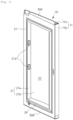
- FIGS. 3 and 4 are views showing only the structure of the sub door 1 without the main door 100.
- a first door body 10 the second door body 20, an upper cover 30A, and a lower cover 30B may be coupled to each other to form one frame constituting the sub door 1.
- the first door body 10 constitutes relatively the outer portion and the second door body 20 is coupled to the first door body 10 to face the storage compartment.
- the second door body 20 constitutes the inner surface of the sub door 1.
- the inner surface means a surface that faces the storage compartment of the refrigerator.
- the first door body 10 has a roughly flat plate structure.
- the frame of the first door body 10 may be formed of a door plate 11.
- the door plate 11 includes a front plate 11a forming a front surface of the refrigerator, and a side plate 11b bent from the front plate 11a.
- the front plate 11a and the side plate 11b are connected to each other to form a rough-' ⁇ ' shape.
- the front plate 11a and the side plate 11b are formed in an integrated body.
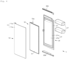
- the second door body 20 may be coupled to the first door body 10 with the vacuum insulation assembly 50 located therebetween.
- the second door body 20 may be coupled to the first door body 10 to form the heat insulating space between the first door body 10 and the second door body 20.
- the heat insulating space is filled with the vacuum insulation assembly 50 and a foam filled part F, which will be described below, and the foam filled part F fills the heat insulating space except for a portion occupied by the vacuum insulation assembly 50.
- the second door body 20 may include a sub frame 21' constituting an outer part thereof, and an inner frame 21 surrounded by the sub frame 21'.
- the sub frame 21' has a roughly rectangular frame shape, and the inner frame 21 is coupled to an inner portion of the sub frame 21' to form the inner surface of the sub door 1.
- the inner frame 21 is recessed in a direction of the first door body 10, i.e., an outward direction of the refrigerator to form the main storage space 122 therein.
- the inner frame 21 includes a first plate 21a forming a side surface of the main storage space 122, and a second plate 21b forming a rear surface of the main storage space 122.
- the rear surface of the main storage space 122 means the inner surface of the sub door 1 facing the storage compartment of the refrigerator.
- the first plate 21a may be a side surface of the inner frame 21
- the second plate 21b may be a rear surface of the rear surface of the inner frame 21 and a bottom surface of the main storage space 122.
- the first plate 21a and the second plate 21b may be formed in an integrated body.
- the first plate 21a has a roughly rectangular frame shape that surrounds edges of the inner frame 21, and the second plate 21b has a flat plate structure.
- the first plate 21a may be understood to protrude along edges of the second plate 21b.
- the first plate 21a may include a hanging part 21a'.
- the hanging part 21a' has a structure that protrudes from the first plate 21a, and the basket 27 (referring to FIG. 6 ) may be fitted thereto.
- the hanging part 21a' may include a plurality of hanging parts 21a' having different heights in the first plate 21a, and in this case, a plurality of baskets 27 may be installed in the main storage space 122.
- the hanging part 21a' may have a structure that is recessed inward of the first plate 21a, not the protruding structure.
- the width of main storage space 122 may be defined from a surface of the second plate constituting the second door body 20 to an end of a dyke part 24.
- a size of the width of the main storage space 122 is marked with L1.
- the vacuum insulation assembly 50 reduces the thickness of the heat insulating structure and the dyke part 24 extends at the same time, so that the width of the main storage space 122 may widen significantly.
- reference numeral 27 shows an end of the first plate 21a facing the main door 100.
- the second door body 20 includes the dyke part 24.
- the dyke part 24 may be understood as a structure extending from the first plate 21a constituting the second door body 20, and the dyke part 24 protrudes in the direction of the storage compartment.
- the dyke part 24 may be provided throughout the entire area of the first plate 21a, and may be provided in some areas.
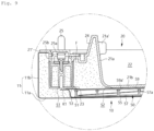
- the dyke part 24 may be also provided in a lower portion of the second door body 20. As shown in FIG. 7 , the dyke part 24 protrudes from the lower portion of the second door body 20 toward the main door 100. In other words, the dyke part 24 protrudes in the direction of the storage compartment. In the embodiment, the dyke part 24 protrudes relatively more than the lower cover 30B constituting a lower structure of the sub door 1 in the direction of the storage compartment (left direction based on FIG. 7 ).
- At least a part of the dyke part 24 may be overlapped with the main door 100.
- the dyke part 24 extends to a position where the dyke part 24 is overlapped with an upper surface of the main cover part 115 constituting the main door 100, and eventually, an end of the dyke part 24 is stacked above the main cover part 115.
- the end of the dyke part 24 may be overlapped with a frame constituting the cabinet of the refrigerator without being overlapped with the upper surface of the main cover part 115.
- a sub gasket may be installed between the main door 100 and the sub door 1, and the end of the dyke part 24 may protrude more than the sub gasket provided between the sub door 1 and the main door 100 in the direction of the storage compartment of the refrigerator.
- FIG. 7 shows an inner space S3, and the sub gasket may be installed in the inner space S3.
- the embodiment since the embodiment has the structure in which the dyke part 24 is overlapped with the main door 100, in order to allow cooling air transmitted from the storage compartment of the refrigerator to flow into the inner space S3 located between the main door 100 and the sub door 1, an indirect route such as arrow shown in FIG. 7 is inevitably required.
- the cool air of the refrigerator does not flow directly into the inner space S3. Therefore, the cool air does not escape easily into the inner space S3, and the cool air lowers the temperature of the sub gasket to prevent dew formation occurring on the sub gasket.
- the inner space S3 serves as a leakage flow path of the cool air, and the dyke part 24 blocks the leakage flow path.
- the cool air of the refrigerator tends to be sunk downward and, in the embodiment, the dyke part 24 blocks an entrance of the leakage flow path (inner space S3) through which the cool air leaks, thereby interrupting a flow of the cool air.
- a surface of the end of the dyke part 24 and a surface of the main cover part 115 located at a position where the main cover part 115 and the dyke part 24 are overlapped with each other may be formed in inclined surfaces corresponding to each other.
- the inclined surfaces allow the end of the dyke part 24 and the main cover part 115 to be naturally guided with each other when the sub door 1 is closed while being rotated toward the main door 100. Furthermore, the inclined surfaces lengthens a section where the dyke part 24 is overlapped with the main door 100, thereby preventing leakage of the cool air efficiently.
- the dyke part 24 is not only located at the lower portion of the second door body 20, but may be provided throughout the entire area of the first plate 21a. Therefore, the dyke part 24 may be overlapped with the entire inner surface of the main door 100 along edges of the main frame 105 of the main door 100. As shown in FIG. 5 , the view shows the dyke part 24 provided not only at the lower portion of the first plate 21a, but also side surfaces thereof.
- the sub door 1 may include a latch means 23, 25.
- the latch means 23, 25 serves to maintain a state in which the sub door 1 is in close contact with the main door 100, and the latch means 23, 25 may prevent the sub door 1 from being arbitrarily opened by an external force.
- the latch means 23, 25 may be configured to be caught or unlocked to the main door 100 while a latch body 25 is rotated or linearly moved.
- a latch housing 23 may be embedded inside the heat insulating space formed between the first door body 10 and the second door body 20, and the latch body 25 may be installed in the latch housing 23.
- the latch housing 23 may be formed in an integrated body with the second door body 20, but may be formed in a separate body from the second door body 20.
- the latch means 23, 25 may include a latch cover 25a covering a peripheral part of the latch body 25 and a mounting part 25b allowing the latch body 25 to be in a mounting state, inside the latch cover 25a.
- an elastic member is provided in the mounting part 25b to provide an elastic force to allow the latch means 23, 25 to be in a caught state.
- a button assembly (not shown) is connected to the latch body 25 to allow the latch means 23, 25 to be turned into an unlocked state when a user operates the latch body 25 while restoring the elastic force of the elastic member.
- all the peripheral part of the latch means 23, 25 in addition to the latch housing 23 may be filled with the foam filled part F.
- a remaining portion of the heat insulating space except for the vacuum insulation assembly 50 is filled with the foam filled part F.
- the most portion of the heat insulating space is occupied by the vacuum insulation assembly 50, and the space occupied by the vacuum insulation assembly 50 has a very narrow width.
- the foam filled part F is filled only in edge portions of the sub door 1 corresponding to opposite ends of the vacuum insulation assembly 50.
- the portion filled with the foam filled part F is limited to an edge of the heat insulating space, so that amount of injection and foaming time of a filler may be reduced. Therefore, the amount of the foam filled part F is sharply reduced, so that the manufacturing speed of the refrigerator door can be increased.
- the foam filled part F serves to surround an edge portion of the vacuum insulation assembly 50 naturally to fix the edge, so that even when a separate fixing device is not provided the vacuum insulation assembly 50 can be securely fixed without interference with the peripheral part.
- the vacuum insulation assembly 50 may be inserted into the heat insulating space.
- the vacuum insulation assembly 50 serves as the heat insulating function of the sub door 1, and an inside portion thereof is formed in the vacuum chamber.
- the vacuum chamber may increase the heat insulation function of the sub door 1 significantly, but only the vacuum chamber is insufficient to prevent transmission of an internal radiant heat, so that the vacuum insulation assembly 50 includes a radiant heat shield film 55 in the embodiment.
- the vacuum insulation assembly 50 may have a roughly rectangular plate structure. As shown in FIGS. 8 and 10 , the vacuum insulation assembly 50 may have a transverse width and a vertical height similar to an entire transverse length (referring to FIG. 8 ) of the sub door 1 and an entire vertical height (referring to FIG. 10 ) of the sub door 1. However, the edge of the vacuum insulation assembly 50 is spaced apart from an inner surface of the heat insulating space of the sub door 1 by a predetermined distance. At this point, the edge of the vacuum insulation assembly 50 means an end portion formed while wrapping corners of the vacuum insulation assembly 50.
- FIG. 11 is an exploded-perspective view showing parts constituting the vacuum insulation assembly 50.
- the vacuum insulation assembly 50 includes a first casing 51 and a second casing 53 that form outer portions, and a radiant heat prevention part 55, 57, 59 embedded between the first casing 51 and the second casing 53.
- Each of the first casing 51 and the second casing 53 may have a rectangular plate structure.
- the first casing 51 and the second casing 53 may be made of a metal material. Then, in a process in which the inside space of the vacuum insulation assembly 50 is changed into the vacuum chamber through an exhaust port 53a, strong pressure and high temperature may be applied to the first casing 51 and the second casing 53. In order to endure the conditions, it is preferable that the first casing 51 and the second casing 53 are made of a metal material having high strength. At this point, the first casing 51 and the second casing 53 may be made of various materials such as steel sheet, stainless steel, alloy plate, etc.
- a bent part 52 may be provided on an edge of the first casing 51.
- the bent part 52 is a part bent to protrude in a direction of a surface of the second casing 53, and a surface of the first casing 51 has roughly a recessed shape by the bent part 52, the surface facing an inner surface of the first casing 51, i.e., the second casing 53.
- the inside space of the first casing 51 having the recessed shape becomes the vacuum chamber, and at the same time serves, becomes a space into which the radiant heat prevention part 55, 57, 59 is inserted.
- the bent part 52 may be joined to an edge part 54 of the second casing 53.
- the exhaust port 53a may be formed in the second casing 53.
- the exhaust port 53a protrudes on the second casing 53, and has a kind of hollow tube structure. Air inside the vacuum chamber may be discharged to the external space through the exhaust port 53a, and then the degree of vacuum inside the vacuum chamber can be increased.
- the exhaust port 53a may be cut out with remaining a part thereof after an exhaust process is finished, and in a cutting process, an end of the exhaust port 53a is compressed to allow the vacuum chamber to be maintained in a vacuum state.
- the exhaust port 53a may be fixed to the second door body 20 in a manufacturing process of the sub door 1, or may be fixed while being embedded the inside portion of the foam filled part F, inside the heat insulating space.
- the first casing 51 may be fixed to an inner surface of the first door body 10, and a coupling part K1 provided on the edge of the first casing 51 may be spaced apart from the inner surface of the first door body 10. As shown in FIG. 8 , the coupling part K1 formed on each of the opposite ends of the first casing 51 is spaced apart from the inner surface of the first door body 10, more precisely, from the front plate 11a.
- the first casing 51 may be temporarily fixed to an inner surface of the front plate 11a with an adhesive, an adhesive tape, or the like.
- the entire vacuum insulation assembly 50 including the first casing 51 may be turned in a completely fixed state with respect to an inside portion of the sub door 1.
- the radiant heat shield film 55 may be provided at a middle portion, and spacers 57 and 59 may be provided at opposite sides of the radiant heat shield film 55, respectively.
- the spacers 57 and 59 include a first spacer 57 and a second spacer 59.
- the first spacer 57 is close to the first casing 51
- the second spacer 59 is close to the second casing 53.
- the spacers 57 and 59 prevent the radiant heat shield film 55 from being brought into contact with the surface of the first casing 51 or the surface of the second casing 53.
- the radiant heat shield film 55 may be made of an aluminum material, be made by attaching an aluminum metallized film on an injection-molded object, or be made by metalcoating on a surface of a thin plate of various materials.
- a plurality of radiant heat shield films 55 may be provided inside the vacuum insulation assembly 50.
- the radiant heat shield film 55 may be divided into a plurality of radiant heat shields for convenience in manufacture and assembly, but may be formed in a single part. Otherwise, the radiant heat shield film 55 may be formed by staking a plurality of radiant heat shield films. In other words, the radiant heat shield films 55 may be stacked to each other with gaps from each other between the pair of spacers 57 and 59.
- a coupling hole 55a may be formed in the radiant heat shield film 55.
- the coupling hole 55a is formed by penetrating through the radiant heat shield film 55, and a plurality of coupling holes 55a may be formed in the radiant heat shield film 55.
- the pair of spacers 57 and 59 constituting the radiant heat prevention part 55, 57, 59 may be assembled to each other through the coupling hole 55a.
- a boss part 57a may protrude on the first spacer 57 in a cylindrical shape, and an assembly groove 59a coupled to the boss part 57a may be formed on the second spacer 59 located opposite to the first spacer 57 with the radiant heat shield film 55 located therebetween. An end of the boss part 57a may be coupled to the assembly groove 59a. At this point, the boss part 57a passes through the coupling hole to be fitted in the assembly groove 59a, so that the radiant heat shield film 55 eventually is installed between the first spacer 57 and the second spacer 59.
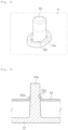
- the entire height H1 of the vacuum insulation assembly 50 may be a distance between the first casing 51 and the second casing 53. It is only necessary to provide the vacuum chamber, the entire height H1 of the vacuum insulation assembly 50 may be formed relatively short. Specifically, the radiant heat shield film 55 has a thin plate shape, so that the entire height H1 of the vacuum insulation assembly 50 may be lowered.
- the radiant heat shield film 55 has a thin plate shape, and the plurality of coupling holes 55a may be formed at constant gaps.
- each of the coupling holes 55a is a circular hole, but the shape of the coupling hole 55a may be formed in various shapes.
- the circular coupling holes 55a are shown in FIG. 13 , but a roughly oval coupling hole 55a is shown in FIG. 14 .
- a burring part 55a' may be provided on a rim of the coupling hole 55a.
- the rim of the coupling hole 55a means a portion formed by surrounding an inner surface of the coupling hole 55a, and the burring part 55a' may be formed by surrounding the rim of the coupling hole 55a.
- the burring part 55a' is formed in a bent shape to increase the thickness, i.e., the entire height of the coupling hole 55a.
- the burring part 55a' extends in a longitudinal direction of the boss part 57a of the first spacer 57 to wrap a surface of the boss part 57a.
- FIG. 15 is a view showing the surface of the boss part 57a that has passed through the coupling hole 55a, the surface of the boss part 57a being wrapped by the boss part 57a.
- the coupling hole 55a has an oval shape, or may have a circular shape like a cross sectional area of the boss part 57a.
- the boss part 57a has a shape of which a width narrows gradually in an upward direction, and in other words, the boss part 57a may be formed such that the width thereof increases gradually toward a surface of the first spacer 57.
- a width of a protruding end of the boss part 57a is smaller than an inner diameter of the coupling hole 55a, but a width of a lower end of the boss part 57a connected to the first spacer 57 is larger than the inner diameter of the coupling hole 55a. Therefore, when the boss part 57a is fitted in the coupling hole 55a, as shown in FIG.
- FIG. 16 is a view showing the burring part 55a' of which the inner surface is in surfacecontact with the outer surface of the boss part 57a. Then, the raised and lowered movements of the radiant heat shield film 55 between the pair of spacers 57 and 59 may be restricted.
- the movements of the radiant heat shield film 55 is restricted, in a process in which the sub door 1 is opened and closed, noise generated when the radiant heat shield film 55 hits the pair of spacers 57 and 59, or noise generated when the radiant heat shield film 55 is bent itself can be prevented.
- the radiant heat shield film 55 may include a bead part 55b.
- the bead part 55b protrudes from the radiant heat shield film 55 toward an inner surface of the first casing 51 or an inner surface of the second casing 53, and may be formed in a punching process.
- the bead part 55b is a structure that reinforces the strength of the radiant heat shield film 55 having a thin plate shape.
- the bead part 55b reinforces the strength of the thin radiant heat shield film 55 to more reduce noise generated when the radiant heat shield film 55 is shaken.
- the bead part 55b may be formed between the coupling holes 55a.
- the bead part 55b and the coupling hole 55a are alternately disposed on the radiant heat shield film 55.
- a plurality of bead parts 55b may be provided in the radiant heat shield film 55.
- each of the bead parts 55b is formed larger than the coupling hole 55a, and the bead part 55b has a circulardepressed structure.
- the bead part 55b may be only formed to have the depth that is sufficient to prevent the head part 55b not to be in contact with the inner surface of the first casing 51 or the inner surface of the second casing 53.
- the bead part 55b may not be formed in a circular shape but may be formed in various shapes, and the size thereof may be various.
- the pair of the spacers 57 and 59 includes the first spacer 57 and the second spacer 59, and the spacers may be made of a material that is relatively light and with low heat conductivity such as a resin injection molded object.
- the first spacer 57 and the second spacer 59 may be disposed at opposite sides of the radiant heat shield film 55.
- the boss part 57a of the first spacer 57 passes through the coupling hole 55a, and the end of the boss part 57a may be assembled to the second spacer 59. More precisely, the assembly groove 59a is formed in the second spacer 59 and the end of the boss part 57a may be fixed by the assembly groove 59a.
- the boss part 57a is fixed inside the assembly groove 59a, the first spacer 57 and the second spacer 59 are assembled to each other with the radiant heat shield film 55 located therebetween.
- a flange part 59a' may protrude on the second spacer 59 in a direction of the first spacer 57, and the assembly groove 59a may be formed inside the flange part 59a'.
- the flange part 59a' is not inserted into the coupling hole 55a, and may support a peripheral part of the rim of the coupling hole 55a.
- first casing 51 and the second casing 53 are joined with each other to seal the vacuum chamber.
- the first casing 51 and the second casing 53 are joined while the bent part 52 of the first casing 51 is in close contact with the surface of the second casing 53.
- the first casing 51 may be joined with the second casing 53 by a welding method.
- the first casing 51 and the second casing 53 may be joined with each other by an ultrasonic welding method.
- the first casing 51 and the second casing 53 may have the coupling part K1 where the first casing 51 and the second casing 53 are joined with each other, and the coupling part K1 may be continuously formed along the edge of the vacuum insulation assembly 50.
- the coupling part K1 is formed along the edge of the vacuum insulation assembly 50, the inner volume of the vacuum chamber can be secured as wide as possible.
- the peripheral part means all of various parts provided in the heat insulating space and, for example, the latch housing 23 embedded in the heat insulating space, the inner surface of the second door body 20, etc. may be understood as the peripheral part.
- the coupling part K1 may have a gap space between the coupling part K1 and the peripheral part in order to prevent interference with the peripheral part.
- FIG. 8 that is an enlarged view showing part A in FIG. 8 , a first gap space S1 is provided between the coupling part K1 and the latch housing 23.
- the first gap space S1 is a space formed between the latch housing 23 and the coupling part K1, the latch housing 23 and the coupling part K1 being spaced apart from each other by a predetermined distance.
- the latch housing 23 when the latch housing 23 is omitted, there may be the first gap space S1 between one end extending from the first plate 21a constituting the second door body 20 and the coupling part K1.
- one end of the first plate 21a located in the filling space filled with the foam filled part F and the coupling part K1 are spaced apart from each other, thereby forming the first gap space S1.
- the first gap space S1 that is a kind of an empty space may be filled with the foam filled part F. Therefore, it may be understood that at least a part of the edge of the vacuum insulation assembly 50 including the coupling part K1 is surrounded with the foam filled part F. As described above, the foam filled part F prevents the coupling part K1 from interfering with other parts inside the refrigerator door. Furthermore, the foam filled part F may serve to prevent the vacuum insulation assembly 50 from being shaken inside the sub door 1.
- a connected portion between the first plate 21a and the second plate 21b that constitute the second door body 20 may be spaced apart from the second casing 53 of the vacuum insulation assembly 50. More precisely, the connected portion between the first plate 21a and the second plate 21b may be a kind of an edge, and this portion is a portion most protruding toward the vacuum insulation assembly 50. The connected portion between the first plate 21a and the second plate 21b is spaced apart from the first casing 51 of the vacuum insulation assembly 50, and a second gap space S2 is formed therebetween.
- first gap space S1 and the second gap space S2 may be empty spaces generated as the vacuum insulation assembly 50 and the peripheral part are spaced apart from each other. Furthermore, the first gap space S1 and the second gap space S2 may be filled with the foam filled part F. The foam filled part F allows the vacuum insulation assembly 50 to be spaced apart from the peripheral part, i.e., to maintain the first gap space S1 and the second gap space S2.
- the vacuum insulation assembly 50 When the vacuum insulation assembly 50 is bent in a manufacturing process, or the vacuum insulation assembly 50 has the flat plate structure extending in one direction but the first door body 10 is formed in an entirely curved surface, the vacuum insulation assembly 50 and the first door body 10 may interfere with each other. However, in the embodiment, the first gap space S1 and the second gap space S2 are provided, interference between the vacuum insulation assembly 50 and the peripheral part may be prevented.
- the first gap space S1 may have a width larger than a width of the second gap space S2.
- the first gap space S1 is formed in a portion relatively closer to the edge of the vacuum insulation assembly 50 than the second gap space S2.
- the first gap space S1 is formed in a position close to the coupling part K1, and since the first gap space S1 is larger than the second gap space S2, a risk of interference between the coupling part K1 and the peripheral part (latch housing 23, etc.) may be more reduced.
- the vacuum insulation assembly 50 may be fixed to the inner surface of the first door body 10. As described above, fixation of the vacuum insulation assembly 50 may be performed by fixing the first casing 51 of the vacuum insulation assembly 50 on the inner surface of the front plate 11a of the first door body 10 by an adhesive tape, etc.
- the vacuum insulation assembly 50 is in a formed state of the vacuum chamber therein.
- the vacuum insulation assembly 50 has the vacuum chamber between the first casing 51 and the second casing 53 and the radiant heat prevention part 55, 57, 59 is installed in the vacuum chamber.
- the radiant heat prevention part 55, 57, 59 may include the pair of spacers 57 and 59, and the radiant heat shield film 55 fixed between the pair of spacers 57 and 59.
- the second spacer 59 is assembled at the opposite side at the same time.
- the radiant heat shield film 55 is fixed between the first spacer 57 and the second spacer 59.
- the burring part 55a' of the radiant heat shield film 55 may increase the contact area with the boss part 57a protruding on the first spacer 57, and then a movement of the radiant heat shield film 55 raised and lowered between the spacers 57 and 59 may be restricted.
- the movement of the radiant heat shield film 55 is restricted, in a process in which the sub door 1 is opened and closed, noise generated when the radiant heat shield film 55 hits the pair of spacers 57 and 59, or noise generated when the radiant heat shield film 55 is bent itself can be prevented.
- the first casing 51 and the second casing 53 may be assembled with each other with the radiant heat prevention part 55, 57, 59 located therebetween and an assembly therebetween may be performed by a welding method.
- a welding portion may be the coupling part K1.
- the vacuum chamber is formed between the first casing 51 and the second casing 53.
- vacuum exhaust may be performed by inserting the vacuum insulation assembly 50 into a heating furnace.
- a leakage test may be performed to check whether or not leakage occurs in the vacuum chamber.
- the exhaust port 53a is pinched off to seal the vacuum chamber from the external space.
- the foam filled part F surrounding the edge of the vacuum insulation assembly 50 may be formed.
- the foam filled part F serves to surround and fix an edge portion of the vacuum insulation assembly 50, specifically, the coupling part K1, naturally, so that even when a separate fixing device is not provided, the vacuum insulation assembly 50 can be securely fixed without interference with the peripheral part.
- the coupling part K1 of the vacuum insulation assembly 50 may be maintained in a state of being spaced apart from the peripheral part.
- the foam filled part F prevents the coupling part K1 from interfering with other parts inside the refrigerator door.
- the foam filled part F may serve to prevent the vacuum insulation assembly 50 from being shaken inside the sub door 1.
Landscapes
- Engineering & Computer Science (AREA)
- General Engineering & Computer Science (AREA)
- Mechanical Engineering (AREA)
- Chemical & Material Sciences (AREA)
- Combustion & Propulsion (AREA)
- Physics & Mathematics (AREA)
- Thermal Sciences (AREA)
- Refrigerator Housings (AREA)
Applications Claiming Priority (2)
| Application Number | Priority Date | Filing Date | Title |
|---|---|---|---|
| KR1020200144610A KR20220059252A (ko) | 2020-11-02 | 2020-11-02 | 진공단열조립체를 구비한 냉장고 도어 및 그 제조방법 |
| PCT/KR2021/015603 WO2022092975A1 (fr) | 2020-11-02 | 2021-11-01 | Porte de réfrigérateur ayant un ensemble d'isolation sous vide et son procédé de fabrication |
Publications (1)
| Publication Number | Publication Date |
|---|---|
| EP4239264A1 true EP4239264A1 (fr) | 2023-09-06 |
Family
ID=81382953
Family Applications (1)
| Application Number | Title | Priority Date | Filing Date |
|---|---|---|---|
| EP21886969.1A Pending EP4239264A1 (fr) | 2020-11-02 | 2021-11-01 | Porte de réfrigérateur ayant un ensemble d'isolation sous vide et son procédé de fabrication |
Country Status (4)
| Country | Link |
|---|---|
| US (1) | US20230400245A1 (fr) |
| EP (1) | EP4239264A1 (fr) |
| KR (1) | KR20220059252A (fr) |
| WO (1) | WO2022092975A1 (fr) |
Family Cites Families (7)
| Publication number | Priority date | Publication date | Assignee | Title |
|---|---|---|---|---|
| US20040226956A1 (en) | 2003-05-14 | 2004-11-18 | Jeff Brooks | Cryogenic freezer |
| KR101203997B1 (ko) * | 2005-12-22 | 2012-11-23 | 삼성전자주식회사 | 냉장고 |
| KR102525551B1 (ko) * | 2015-08-03 | 2023-04-25 | 엘지전자 주식회사 | 진공단열체 및 냉장고 |
| KR102529852B1 (ko) * | 2015-08-03 | 2023-05-08 | 엘지전자 주식회사 | 진공단열체 및 냉장고 |
| KR102447245B1 (ko) * | 2015-08-03 | 2022-09-27 | 엘지전자 주식회사 | 진공단열체 및 냉장고 |
| KR102442973B1 (ko) * | 2015-08-03 | 2022-09-14 | 엘지전자 주식회사 | 진공단열체 및 냉장고 |
| KR102459784B1 (ko) | 2017-08-01 | 2022-10-28 | 엘지전자 주식회사 | 진공단열체 및 냉장고 |
-
2020
- 2020-11-02 KR KR1020200144610A patent/KR20220059252A/ko active Search and Examination
-
2021
- 2021-11-01 EP EP21886969.1A patent/EP4239264A1/fr active Pending
- 2021-11-01 US US18/035,023 patent/US20230400245A1/en active Pending
- 2021-11-01 WO PCT/KR2021/015603 patent/WO2022092975A1/fr unknown
Also Published As
| Publication number | Publication date |
|---|---|
| KR20220059252A (ko) | 2022-05-10 |
| US20230400245A1 (en) | 2023-12-14 |
| WO2022092975A1 (fr) | 2022-05-05 |
Similar Documents
| Publication | Publication Date | Title |
|---|---|---|
| US8167389B2 (en) | Refrigerator mullion with protection unit | |
| EP3553430A1 (fr) | Réfrigérateur comprenant un espace vide | |
| KR20140060429A (ko) | 냉장고 및 그 내부 도어의 제조 방법 | |
| KR20010022959A (ko) | 단열 벽 | |
| KR20140060145A (ko) | 냉장고 및 그 내부 도어의 제조 방법 | |
| US5560694A (en) | Labyrinth door seal for a refrigerator | |
| KR101350025B1 (ko) | 냉장고용 홈바 | |
| JP7137367B2 (ja) | 冷蔵庫 | |
| JP2011112290A (ja) | 冷蔵庫 | |
| JP7141492B2 (ja) | 冷蔵庫 | |
| EP4239264A1 (fr) | Porte de réfrigérateur ayant un ensemble d'isolation sous vide et son procédé de fabrication | |
| RU2606789C1 (ru) | Охлаждающий шкаф | |
| JP2012037151A (ja) | 冷凍機器 | |
| KR19990068226A (ko) | 냉각 저장고 | |
| US11585590B2 (en) | Sealing assembly for cooling device doors and cooling device having the sealing assembly | |
| JP2021119325A (ja) | 冷蔵庫 | |
| WO2013058257A1 (fr) | Appareil de type porte pour réfrigérateur | |
| JP2013100942A (ja) | 冷蔵庫 | |
| CN109387010B (zh) | 冰箱 | |
| JP2018119696A (ja) | センターシールの取付構造 | |
| WO2009061069A1 (fr) | Réfrigérateur et sa porte d'ouverture/fermeture | |
| JP7183448B2 (ja) | 冷蔵庫 | |
| WO2023152996A1 (fr) | Porte isolée et stockage | |
| JP6292990B2 (ja) | 冷蔵庫 | |
| CN112204327B (zh) | 冷却装置的隔热结构及冷却装置 |
Legal Events
| Date | Code | Title | Description |
|---|---|---|---|
| STAA | Information on the status of an ep patent application or granted ep patent |
Free format text: STATUS: THE INTERNATIONAL PUBLICATION HAS BEEN MADE |
|
| PUAI | Public reference made under article 153(3) epc to a published international application that has entered the european phase |
Free format text: ORIGINAL CODE: 0009012 |
|
| STAA | Information on the status of an ep patent application or granted ep patent |
Free format text: STATUS: REQUEST FOR EXAMINATION WAS MADE |
|
| 17P | Request for examination filed |
Effective date: 20230526 |
|
| AK | Designated contracting states |
Kind code of ref document: A1 Designated state(s): AL AT BE BG CH CY CZ DE DK EE ES FI FR GB GR HR HU IE IS IT LI LT LU LV MC MK MT NL NO PL PT RO RS SE SI SK SM TR |
|
| DAV | Request for validation of the european patent (deleted) | ||
| DAX | Request for extension of the european patent (deleted) |