EP4239245B1 - Beleuchtungsvorrichtung - Google Patents
Beleuchtungsvorrichtung Download PDFInfo
- Publication number
- EP4239245B1 EP4239245B1 EP22871069.5A EP22871069A EP4239245B1 EP 4239245 B1 EP4239245 B1 EP 4239245B1 EP 22871069 A EP22871069 A EP 22871069A EP 4239245 B1 EP4239245 B1 EP 4239245B1
- Authority
- EP
- European Patent Office
- Prior art keywords
- lighting
- lighting device
- connecting part
- assembly
- connector
- Prior art date
- Legal status (The legal status is an assumption and is not a legal conclusion. Google has not performed a legal analysis and makes no representation as to the accuracy of the status listed.)
- Active
Links
Images


Classifications
-
- F—MECHANICAL ENGINEERING; LIGHTING; HEATING; WEAPONS; BLASTING
- F21—LIGHTING
- F21V—FUNCTIONAL FEATURES OR DETAILS OF LIGHTING DEVICES OR SYSTEMS THEREOF; STRUCTURAL COMBINATIONS OF LIGHTING DEVICES WITH OTHER ARTICLES, NOT OTHERWISE PROVIDED FOR
- F21V21/00—Supporting, suspending, or attaching arrangements for lighting devices; Hand grips
- F21V21/14—Adjustable mountings
-
- F—MECHANICAL ENGINEERING; LIGHTING; HEATING; WEAPONS; BLASTING
- F21—LIGHTING
- F21S—NON-PORTABLE LIGHTING DEVICES; SYSTEMS THEREOF; VEHICLE LIGHTING DEVICES SPECIALLY ADAPTED FOR VEHICLE EXTERIORS
- F21S6/00—Lighting devices intended to be free-standing
-
- F—MECHANICAL ENGINEERING; LIGHTING; HEATING; WEAPONS; BLASTING
- F21—LIGHTING
- F21S—NON-PORTABLE LIGHTING DEVICES; SYSTEMS THEREOF; VEHICLE LIGHTING DEVICES SPECIALLY ADAPTED FOR VEHICLE EXTERIORS
- F21S9/00—Lighting devices with a built-in power supply; Systems employing lighting devices with a built-in power supply
- F21S9/02—Lighting devices with a built-in power supply; Systems employing lighting devices with a built-in power supply the power supply being a battery or accumulator
-
- F—MECHANICAL ENGINEERING; LIGHTING; HEATING; WEAPONS; BLASTING
- F21—LIGHTING
- F21V—FUNCTIONAL FEATURES OR DETAILS OF LIGHTING DEVICES OR SYSTEMS THEREOF; STRUCTURAL COMBINATIONS OF LIGHTING DEVICES WITH OTHER ARTICLES, NOT OTHERWISE PROVIDED FOR
- F21V21/00—Supporting, suspending, or attaching arrangements for lighting devices; Hand grips
- F21V21/06—Bases for movable standing lamps; Fixing standards to the bases
-
- F—MECHANICAL ENGINEERING; LIGHTING; HEATING; WEAPONS; BLASTING
- F21—LIGHTING
- F21V—FUNCTIONAL FEATURES OR DETAILS OF LIGHTING DEVICES OR SYSTEMS THEREOF; STRUCTURAL COMBINATIONS OF LIGHTING DEVICES WITH OTHER ARTICLES, NOT OTHERWISE PROVIDED FOR
- F21V21/00—Supporting, suspending, or attaching arrangements for lighting devices; Hand grips
- F21V21/10—Pendants, arms, or standards; Fixing lighting devices to pendants, arms, or standards
- F21V21/116—Fixing lighting devices to arms or standards
-
- F—MECHANICAL ENGINEERING; LIGHTING; HEATING; WEAPONS; BLASTING
- F21—LIGHTING
- F21V—FUNCTIONAL FEATURES OR DETAILS OF LIGHTING DEVICES OR SYSTEMS THEREOF; STRUCTURAL COMBINATIONS OF LIGHTING DEVICES WITH OTHER ARTICLES, NOT OTHERWISE PROVIDED FOR
- F21V21/00—Supporting, suspending, or attaching arrangements for lighting devices; Hand grips
- F21V21/14—Adjustable mountings
- F21V21/22—Adjustable mountings telescopic
-
- F—MECHANICAL ENGINEERING; LIGHTING; HEATING; WEAPONS; BLASTING
- F21—LIGHTING
- F21V—FUNCTIONAL FEATURES OR DETAILS OF LIGHTING DEVICES OR SYSTEMS THEREOF; STRUCTURAL COMBINATIONS OF LIGHTING DEVICES WITH OTHER ARTICLES, NOT OTHERWISE PROVIDED FOR
- F21V21/00—Supporting, suspending, or attaching arrangements for lighting devices; Hand grips
- F21V21/14—Adjustable mountings
- F21V21/30—Pivoted housings or frames
-
- F—MECHANICAL ENGINEERING; LIGHTING; HEATING; WEAPONS; BLASTING
- F21—LIGHTING
- F21V—FUNCTIONAL FEATURES OR DETAILS OF LIGHTING DEVICES OR SYSTEMS THEREOF; STRUCTURAL COMBINATIONS OF LIGHTING DEVICES WITH OTHER ARTICLES, NOT OTHERWISE PROVIDED FOR
- F21V23/00—Arrangement of electric circuit elements in or on lighting devices
- F21V23/06—Arrangement of electric circuit elements in or on lighting devices the elements being coupling devices, e.g. connectors
-
- F—MECHANICAL ENGINEERING; LIGHTING; HEATING; WEAPONS; BLASTING
- F21—LIGHTING
- F21V—FUNCTIONAL FEATURES OR DETAILS OF LIGHTING DEVICES OR SYSTEMS THEREOF; STRUCTURAL COMBINATIONS OF LIGHTING DEVICES WITH OTHER ARTICLES, NOT OTHERWISE PROVIDED FOR
- F21V29/00—Protecting lighting devices from thermal damage; Cooling or heating arrangements specially adapted for lighting devices or systems
- F21V29/50—Cooling arrangements
- F21V29/70—Cooling arrangements characterised by passive heat-dissipating elements, e.g. heat-sinks
-
- F—MECHANICAL ENGINEERING; LIGHTING; HEATING; WEAPONS; BLASTING
- F21—LIGHTING
- F21W—INDEXING SCHEME ASSOCIATED WITH SUBCLASSES F21K, F21L, F21S and F21V, RELATING TO USES OR APPLICATIONS OF LIGHTING DEVICES OR SYSTEMS
- F21W2131/00—Use or application of lighting devices or systems not provided for in codes F21W2102/00-F21W2121/00
- F21W2131/40—Lighting for industrial, commercial, recreational or military use
- F21W2131/402—Lighting for industrial, commercial, recreational or military use for working places
-
- F—MECHANICAL ENGINEERING; LIGHTING; HEATING; WEAPONS; BLASTING
- F21—LIGHTING
- F21Y—INDEXING SCHEME ASSOCIATED WITH SUBCLASSES F21K, F21L, F21S and F21V, RELATING TO THE FORM OR THE KIND OF THE LIGHT SOURCES OR OF THE COLOUR OF THE LIGHT EMITTED
- F21Y2115/00—Light-generating elements of semiconductor light sources
- F21Y2115/10—Light-emitting diodes [LED]
-
- Y—GENERAL TAGGING OF NEW TECHNOLOGICAL DEVELOPMENTS; GENERAL TAGGING OF CROSS-SECTIONAL TECHNOLOGIES SPANNING OVER SEVERAL SECTIONS OF THE IPC; TECHNICAL SUBJECTS COVERED BY FORMER USPC CROSS-REFERENCE ART COLLECTIONS [XRACs] AND DIGESTS
- Y02—TECHNOLOGIES OR APPLICATIONS FOR MITIGATION OR ADAPTATION AGAINST CLIMATE CHANGE
- Y02B—CLIMATE CHANGE MITIGATION TECHNOLOGIES RELATED TO BUILDINGS, e.g. HOUSING, HOUSE APPLIANCES OR RELATED END-USER APPLICATIONS
- Y02B20/00—Energy efficient lighting technologies, e.g. halogen lamps or gas discharge lamps
- Y02B20/40—Control techniques providing energy savings, e.g. smart controller or presence detection
Definitions
- the present disclosure relates to the technical field of lighting and in particular to a lighting device.
- the height of the lighting device is usually adjusted through a parallel four-bar structure or a hose structure, which generally has the problems of a small moving range, troublesome assembly and use, large volume, and inconvenient storage and carrying.
- the angle of the lighting device can only be adjusted in the vertical direction, and the range of adjustment is very limited, which is impossible to adjust from a larger angle.
- the design of the existing lighting device results in a poor user's experience.
- the US patent application publication no. US2019107263A1 discloses a stand light.
- the stand light includes a telescoping body having a main center shaft, an extension pole extendable out of the main center shaft, and a sleeve movably supported on the main center shaft.
- a head assembly is supported by the extension pole and includes a light source.
- a plurality of legs is pivotally coupled to the body and is movable with the sleeve from a collapsed position to an extended position, in which distal ends of the plurality of legs are moved away from the body. When the plurality of legs is in the collapsed position, side portions of the plurality of legs come together to form a handle configured to be grasped by a user.
- the US patent application publication no. US2018119935A1 discloses a site light.
- the site light includes a body, an arm coupled to the body having an adjustable arm length, a light assembly coupled to the arm opposite the body, and a drive mechanism with a crank arm rotatable about a first axis. Rotating the crank arm in a first direction causes the arm length to increase. Rotating the crank arm in a second direction causes the arm length to decrease.
- the drive mechanism is adjustable between a first configuration, where the crank arm can only rotate in the first direction, and a second configuration, where the crank arm can be rotated in the first direction and the second direction.
- the EP application publication no. EP2325552A1 discloses a collapsible lighting device.
- the collapsible lighting device has a main body surrounded by a collar whose position is adjustable along the longitudinal axis of the main body. Pivotally connected or hinged legs are attached to the collar and to the main body with struts. When the collar is on one position, the legs deploy outward from the main body to the extent permitted by the struts, thereby allowing the legs to support the collapsible lighting device upright.
- a lamp head is attached to a member which telescope from the main body. When deployed, the lamp head can be switched on to provide illumination. When the collar is another position, the legs are drawn in toward the main body to form a cylindrical shape.
- the lamp head can be positioned so that when the telescoping member is retracted into the main body, the collar surrounds the exterior of the lamp head, thus protecting the lamp head for transport.
- the overall cylindrical shape of the lighting device in the collapsed position facilitates transport, for example using a strap to carry the device on one's back.
- the present disclosure provides a lighting device, which solves the technical problems of the existing lighting device, such as small height and angle adjustment ranges and inconvenient use and carrying.
- the present disclosure provides a lighting device, which includes:
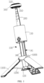
- the lighting device includes the base assembly provided therein with the circuit board; the telescopic assembly provided with the fixed end and the free end that are arranged oppositely, where the fixed end is connected to the base assembly; and the lighting assembly rotatably connected to the free end to rotate relative to the free end, where the lighting assembly is provided with the lighting element electrically connected to the circuit board.
- the extension and retraction of the lighting assembly and the lighting element are realized through the telescopic assembly, such that the height adjustment of the lighting device can be realized in a large range, which is convenient for storage and carrying.
- the lighting assembly since the lighting assembly is movably connected to the free end, the lighting assembly is rotatable axially and radially along the free end. That is, the angle of the lighting assembly can be adjusted in the horizontal and vertical directions to meet different lighting angles, thereby improving the user's experience.
- the present disclosure provides a lighting device.
- the lighting device includes base assembly 100 provided therein with circuit board 110; telescopic assembly 200 provided with fixed end 210 and free end 220 that are arranged oppositely, where the fixed end 210 is connected to the base assembly 100; and lighting assembly 300 rotatably connected to the free end 220 to rotate axially and radially along the free end 220, where the lighting assembly 300 is provided with lighting element 310 electrically connected to the circuit board 110.
- the base assembly 100 may be placed on the ground or adsorbed to an iron article.
- the base assembly 100 may also be adsorbed in a region at a high position such as an iron ceiling to realize a different use scenario.
- the use scenarios of the lighting device are not limited herein.
- the telescopic assembly 200 can adapt to lighting scenarios of different heights.
- the length of the telescopic assembly 200 may also be appropriately increased according to different lighting scenarios.
- the telescopic assembly 200 is retracted such that the lighting assembly 300 and the base assembly 100 can be stored together, thereby reducing the occupied space of the lighting device and facilitating the carrying of the lighting device.
- the free end 220 is an end that can be stretched or contracted
- the fixed end 210 is an end that is configured to fix the telescopic assembly 200.
- the free end 220 is stored in the fixed end 210.
- the telescopic assembly 200 is in an extended state.
- the telescopic assembly 200 further has a fully extended or partially extended state, which can be set according to the actual lighting scenario of the lighting device and is not limited herein.
- the lighting assembly 300 is provided on the free end 220 of the telescopic assembly 200.
- the lighting assembly 300 can move in a direction away from the fixed end 210 with the extension of the free end 220, thereby increasing the height of the lighting assembly 300.
- the lighting assembly 300 can move in a direction toward the fixed end 210 with the retraction of the free end 220, thereby reducing the height of the lighting assembly 300.
- the lighting assembly 300 since the lighting assembly 300 is rotatably connected to the free end 220, the lighting assembly 300 is rotatable axially and radially along the free end 220. Therefore, the lighting element 310 is adjustable in height and is rotatable axially and radially along the free end 220.
- the lighting element 310 is a light-emitting plate, which may include a plurality of light-emitting diode (LED) lamps in parallel and/or in series.
- LED light-emitting diode
- the extension and retraction of the lighting assembly 300 and the lighting element 310 are realized through the telescopic assembly 200, such that the height adjustment of the lighting device can be realized in a large range, which is convenient for storage and carrying. Since the lighting assembly 300 is movably connected to the free end 220, the lighting assembly 300 is rotatable axially and radially along the free end 220. That is, the angle of the lighting assembly 300 can be adjusted in the horizontal and vertical directions to meet different lighting angles, thereby improving the user's experience.
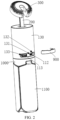
- the base assembly 100 includes base 120, and main body 130 and guide rail element 140 both of which are hollow-through.
- the guide rail element 140 has one end connected to the main body 130 and the other end connected to the base 120.
- An inner space of the main body 130 is communicated with an inner space of the guide rail element 140.
- the circuit board 110 is provided in the main body 130.
- the fixed end 210 passes through the inner space of the main body 130 and the inner space of the guide rail element 140 in sequence and is connected to the base 120.
- the base assembly 100 may be placed on the ground or adsorbed to an iron article to realize a different use scenario, which is not limited herein.
- the main body 130 is separated from the base 120 through the guide rail element 140.
- the main body 130 and the guide rail element 140 are arranged in a hollow-through structure, and the inner space of the main body 130 is coaxial with the inner space of the guide rail element 140.
- the fixing end 210 can directly pass through the inner space of the main body 130 and the inner space of the guide rail element 140 and be fixed to the base 120. In this way, the telescopic assembly 200 can be stored in the inner space of the main body 130 and the inner space of the guide rail element 140, thereby reducing the space occupied by the telescopic assembly 200.
- the circuit board 110 is provided in the main body 130.
- the circuit board 100 may also be provided in the base 120 to omit the main body 130, thereby saving costs.
- the guide rail element 140 may be connected and combined with the main body 130 and the base 120 by one or more means such as clips, bolts, screws, rivets, and viscous materials, which is not limited herein.
- the lighting device further includes spring wire 400 provided with one end electrically connected to the circuit board 110; and first connector 500 and second connector 600 that are electrically connected.
- the first connector 500 and the second connector 600 are arranged inside the telescopic assembly 200 at the free end 220.
- the other end of the spring wire 400 passes through a gap between the telescopic assembly 200 and the guide rail element 140, then bends and extends into the telescopic assembly 200, and is electrically connected to the first connector 500.
- the second connector 600 is electrically connected to the lighting element 310.
- the maximum outer diameter of the telescopic assembly 200 is smaller than an inner diameter of the guide rail element 140, such that the gap is formed between the telescopic assembly 200 and the guide rail element 140.
- one end of the spring wire 400 is electrically connected to the circuit board 110.
- the other end of the spring wire passes through the gap, bends and extends to the interior of the telescopic assembly 200, and is electrically connected to the first connector 500.
- the first connector 500 is electrically connected to the second connector 600, and the second connector 600 is electrically connected to the lighting element 310. That is, the circuit board 110 is electrically connected to the lighting element 310 through the spring wire 400, the first connector 500, and the second connector 600, thereby controlling the lighting state of the lighting element 310.
- the first connector 500 may be provided with connecting receptacle 510.
- the first connector 500 includes positive elastic piece 520 and negative elastic piece 530 both of which are connected to the other end of the spring wire 400.
- the positive elastic piece 520 and the negative elastic piece 530 are exposed from the inside of the connecting receptacle 510.
- the second connector 600 includes main wire 610, connecting negative electrode 620, and connecting positive electrode 630 all of which are electrically connected to the main wire 610.
- the cross-sectional area of the connecting negative electrode 620 is greater than the cross-sectional area of the connecting positive electrode 630.
- the connecting negative electrode 620 is provided with through groove 640 along the direction of the connecting positive electrode 630, and the connecting positive electrode 630 is provided in the through groove 640 and insulated from the connecting negative electrode 620.
- the connecting positive electrode 630 has a length greater than the length of the connecting negative electrode 620.
- the connecting positive electrode 630 and the connecting negative electrode 620 are inserted into the connecting receptacle 510.
- the connecting positive electrode 630 is fitted to the positive elastic piece 520 in an elastic manner.
- the connecting negative electrode 620 is fitted to the negative elastic piece 530 in the elastic manner.
- the main wire 610 is electrically connected to the lighting element 310.
- the connecting positive electrode 630 of the second connector 600 is inserted in the connecting receptacle 510 of the first connector 500, such that the connecting positive electrode 630 is fitted to the positive elastic piece 520 in the elastic manner to realize point-contact conductivity.
- the connecting negative electrode 620 of the second connector 600 is fitted to the negative elastic piece 530 in the elastic manner to realize point-contact conductivity.
- the first connector 500 and the second connector 600 are electrically connected.
- the gap between the connecting positive electrode 630 and the connecting negative electrode 620 may be filled with an insulating material.
- an insulating material such as insulating glue is provided on the surface of the connecting positive electrode 630 or the connecting negative electrode 620.
- the insulation design is not limited herein.
- the lighting assembly 300 further includes radiator 320.
- the radiator 320 is provided with rotating groove 321.
- the lighting element 310 is fitted to the radiator 320 to dissipate heat of the lighting element 310 through the radiator 320.
- the lighting element 310 is in close contact with the radiator 320 to effectively guide the working heat to the radiator 320 to protect the lighting element 310 from damage due to high temperature.
- a side of the radiator 320 away from the rotating groove 321 is provided with mounting groove 322, and the lighting element 310 is provided in the mounting groove 322.
- the radiator 320 is made of an aluminum alloy.
- the radiator 320 may be made of other material with high heat dissipation performance, which is not limited herein.
- the lighting assembly further includes transparent protective cover 330.
- the transparent protective cover 330 is provided on the mounting groove 322 to protect the lighting element 310. Light from the lighting element 310 can directly penetrate the transparent protective cover 330, such that the light can be uniformly scattered to realize a good lighting effect.
- the lighting assembly 300 includes radiator rear cover 340 that covers the rotating groove 321. The working heat of the lighting element 310 is transmitted to the radiator 320 and the radiator rear cover 340 to protect the lighting element 310 from damage.
- the lighting device includes connecting element 700.
- the connecting element 700 has first connecting part 710 and second connecting part 720 connected to the first connecting part 710.
- the first connecting part 710 is inserted at the free end 220 and connected to the second connector 600 in the telescopic assembly 200.
- the connecting element 700 is rotated with the first connecting part 710 as a rotating shaft.
- the second connecting part 720 is provided in the rotating groove 321, and the lighting assembly 300 is rotated with the second connecting part 720 as a rotating shaft.
- the connecting element 700 is a T-shaped connector.
- the first connecting part 710 of the T-shaped connector is inserted at the free end 220 and connected to the second connector 600 in the telescopic assembly 200.
- the second connecting part 720 of the T-shaped connector is provided in the rotating groove 321 to make the lighting assembly 300 rotate axially and radially along the free end 220.
- a portion where the connecting positive electrode 630 exceeds the connecting negative electrode 620 has a circular structure, and the connecting receptacle 510 is a circular connecting receptacle. After the connecting positive electrode 630 with the circular structure is inserted into the circular connecting receptacle, the second connector 600 and the first connector 500 can realize 360° infinite rotation while being electrically connected.
- the lighting device includes damping rubber ring 730.
- the damping rubber ring 730 is sleeved on the periphery of the second connecting part 720 to improve friction between the second connecting part 720 and the radiator 320 during rotation. In this way, the second connecting part is not easily loosened or shaken or does not make abnormal noises, and its hand sensory feel is improved.
- the main wire 610 passes through the interior of the first connecting part 710 and the interior of the second connecting part 720 in sequence and is electrically connected to the lighting element 310.
- the second connector 600 is externally provided with a telescopic tube rubber sleeve.
- An outer wall of the telescopic tube rubber sleeve is closely connected to the telescopic assembly 200.
- the second connector 600 has a smaller end passing through the telescopic tube rubber sleeve and a larger end with a diameter greater than the inner diameter of the telescopic tube rubber sleeve, such that the larger end of the second connector 600 is clamped inside the telescopic assembly 200 by the telescopic tube rubber sleeve without falling out. Meanwhile, due to the circular plug-in design between the telescopic tube rubber sleeve and the second connector 600, the second connector 600 and the telescopic tube rubber sleeve are rotatable relatively.
- the circuit board 110 is provided with charging interface 112.
- the main body 130 is provided with charging through-hole 131 and mounting through-hole 132 both of which run through an outer wall.
- the charging interface 112 is exposed from the charging through-hole 131.
- the lighting device further includes battery 800.
- the battery 800 is provided in the main body 130 and is electrically connected to the circuit board 110.
- An external power supply device passes through the charging through-hole 131 to be connected to the charging interface 112 to charge the battery 800.
- the lighting device further includes dust cover 900.
- the dust cover 900 is provided in the mounting through-hole 132 and covers the charging through-hole 131.
- the circuit board 110 is provided with a power output interface 113.
- the main body 130 is further provided with power output through-hole 133 running through the outer wall.
- the power output interface 113 is exposed from the power output through-hole 133.
- the power output interface 113 may be connected to an external electric device (such as a mobile phone or tablet) to charge the electric device.
- circuit board 110 is further integrated with a power key, a power indicator, and other components that are exposed to the main body 130.
- the dust cover 900 is clamped in the mounting through-hole 132 through a clamping point, such that the dust cover 900 will not be separated from the main body 130.
- An outer wall of the dust cover 900 is provided with a protruding clamping point, and an outer shell of the main body is provided with a clamping point groove.
- the protruding clamping point and the clamping point groove are fitted with each other.
- the dust cover 900 can be tightly fitted to an outside of the charging through-hole 131 and the power output through-hole 133 due to the tight fit between the protruding clamping point and the clamping point groove.
- the dustproof plug can effectively protect dust and other foreign matters from entering the lighting device to realize a dustproof and beautiful effect.
- the dust cover 900 may be provided with a pull position to open the dust cover 900.
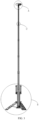
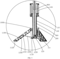
- the lighting device further includes sliding element 1000, a plurality of support legs 1100, support rod 1200, and support and fixing cover 1300.
- the sliding element 1000 is slidably sleeved on the guide rail element 140.
- the support legs 1100 each are provided with rotating end 1110, and the rotating end 1110 is rotatably connected to the sliding element 1000, such that the support legs 1100 each are rotatable toward or away from the sliding element 1000 with the rotating end 1110 as a rotating shaft.
- the support rod 1200 is provided with first connecting end 1210 and second connecting end 1220 that are arranged oppositely.
- the first connecting end 1210 is rotatably connected to a central part of the support leg 1100 through the support and fixing cover 1300.
- the second connecting end 1220 is rotatably connected to the base 120.
- the sliding element 1000 is slidable freely on the guide rail element 140.
- the sliding element 1000 is configured to move to the bottommost position to contact the base 120, and the sliding element will not slide out of the guide member 140 due to the limitation by the base 120.
- the support legs 1100 each are connected and fixed to sliding element 1000 through the rotating end 1110.
- the support legs 1100 each are rotated with the rotating end 1110 as a rotating shaft.
- the support rod 1200 is provided between the support leg 1100 and the base 120.
- the support rod 1200 has one end close to the support leg 1100 serving as the first connecting end 1210 and the other end close to the base 120 serving as the second connecting end 1220.
- the support rod 1200 rotates with the first connecting end 1210 as the rotating shaft.
- the support rod 1200 is rotated with the second connecting end 1220 as a rotating shaft.
- the rotating end 1110, the first connecting end 1210, and the second connecting end 1220 form a triangular structure. That is, the support leg 1100, the support rod 1200, and the sliding element 1000 form a triangle structure, which provides high stability and strength.
- the distance between the rotating end 1110 and the second connecting end 1220 is shortened.
- the downward pressure of the sliding element 1000 and the upward supporting force of the base 120 generate a resultant force toward the first connecting end 1210.
- the support leg 1100 is opened outward under the action of the resultant force. That is, the support leg 1100 is opened to increase the radius of a ground support point.
- the lighting device has a smaller volume and is easy to carry.
- the lighting device further includes a plurality of rubber pad elements 1400.
- the plurality of rubber pad elements 1400 are arranged in the sliding element 1000.
- a plurality of positioning posts 1410 are provided on surfaces of the rubber pad elements 1400 away from the sliding element 1000. The positioning posts 1410 each are arranged in one groove 141.
- the rubber pad elements 1400 are provided in the gap between the inner side of the sliding element 1000 and the outer side of the guide rail element 140.
- One side of each of the rubber pad elements 1400 is provided in the sliding element 1000, and the surface of each of the rubber pad elements 1400 away from the sliding element 1000 is provided with the positioning post 1410.
- the positioning posts 1410 are embedded in the grooves 141, such that the rubber pad elements 1400 and the grooves 141 are always squeezed and stressed, thereby increasing the friction between the sliding element 1000 and the guide rail element 140.
- a side of each of the support legs 1100 away from the rotating end 1110 is provided with magnetic suction piece 1120.
- the base assembly 100 When the base assembly 100 is fixed on a wall, a floor, or a ceiling, the base assembly is adsorbed onto a magnetic material on the wall, the floor, or the ceiling through the magnetic suction piece 1120.
- the design further strengthens the lighting device, improves the stability of the lighting device, and prevents the light from shaking.
- the magnetic suction piece 1120 may be a strong magnet, and the magnetic material may also be a strong magnet.
- the magnetic suction piece 1120 may be a strong magnet, and the magnetic material may be a material that can be adsorbed by the magnet, such as iron, cobalt, nickel or an alloy thereof.
- the magnetic suction piece 1120 may be a material that can be adsorbed by the magnet, such as iron, cobalt, nickel, or an alloy thereof, and the magnetic material may be a strong magnet.
- the materials of the magnetic suction piece and magnetic material are not limited herein.
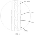
- the telescopic assembly 200 includes a plurality of telescopic rods connected head-to-tail.
- the inner diameters of the telescopic rods decrease progressively from the fixed end 210 to the free end 220.
- the inner diameters of telescopic rods gradually decrease in a direction from the base assembly 100 to the lighting assembly 300. That is, the inner diameter of the telescopic rod closest to the base assembly 100 is the largest, such that other telescopic rods can be stored in the telescopic rod with the largest inner diameter.
- the inner side of the head of the telescopic rod 200a is provided with first rubber pad 201
- the outer side of the tail of the telescopic rod 200b is provided with second rubber pad 202.
- the outer diameter of the second rubber pad 202 is greater than the inner diameter of the first rubber pad 201.
- the second rubber pad 202 is clamped at the first rubber pad 201 to prevent the telescopic rod 200b from sliding out of the telescopic rod 200a during the extension process. Every two adjacent telescopic rods are limited at a connection thereof by rubber pads, or by other soft materials. The limiting means are not limited herein.
- the first rubber pad 201 and the first telescopic rod 200a, as well as the second rubber pad 202 and the telescopic rod 200b, are connected by adhesive glue or other means.
- the design realizes the stable connection between the first rubber pad 201 and the telescopic rod 200a, as well as between the second rubber pad 202 and the telescopic rod 200b.
- the telescopic rods are made of aluminum.
- the telescopic rods may also be made of other materials, such as aluminum alloy, copper, iron, or a composite material, which is not limited herein.
- the lighting device includes the base assembly 100 provided therein with the circuit board 110; the telescopic assembly 200 provided with the fixed end 210 and the free end 220 that are arranged oppositely, where the fixed end 210 is connected to the base assembly 100; and the lighting assembly 300 rotatably connected to the free end 220 to rotate axially and radially along the free end 220, where the lighting assembly 300 is provided with the lighting element 310 electrically connected to the circuit board 110.
- the extension and retraction of the lighting assembly 300 and the lighting element 310 are realized through the telescopic assembly 200, such that the height adjustment of the lighting device can be realized in a large range, which is convenient for storage and carrying.
- the lighting assembly 300 Since the lighting assembly 300 is movably connected to the free end 220, the lighting assembly 300 is rotatable axially and radially along the free end 220. That is, the angle of the lighting assembly 300 can be adjusted in the horizontal and vertical directions to meet different lighting angles, thereby improving the user's experience.
Landscapes
- Engineering & Computer Science (AREA)
- General Engineering & Computer Science (AREA)
- Non-Portable Lighting Devices Or Systems Thereof (AREA)
- Arrangement Of Elements, Cooling, Sealing, Or The Like Of Lighting Devices (AREA)
- Fastening Of Light Sources Or Lamp Holders (AREA)
Claims (13)
- Beleuchtungsvorrichtung, umfassend:eine Basisanordnung (100), wobei eine Leiterplatte (110) in der Basisanordnung (100) vorgesehen ist;eine Teleskopanordnung (200), die mit einem befestigten Ende (210) und einem losen Ende (220) versehen ist, die einander gegenüberliegend angeordnet sind, wobei das befestigte Ende (210) mit der Basisanordnung (100) verbunden ist; undeine Beleuchtungsbaugruppe (300), die drehbar mit dem losen Ende (220) verbunden ist, um sich axial und radial entlang des losen Endes (220) zu drehen, und die mit einem Beleuchtungselement (310) versehen ist, das elektrisch mit der Leiterplatte (110) verbunden ist;wobeidie Basisanordnung (100) eine Basis (120) und einen Hauptkörper (130) und ein Führungsschienenelement (140) umfasst, die beide hohl sind; wobei das Führungsschienenelement (140) ein Ende aufweist, das mit dem Hauptkörper (130) verbunden ist, und das andere Ende, das mit der Basis (120) verbunden ist; ein Innenraum des Hauptkörpers (130) mit einem Innenraum des Führungsschienenelements (140) in Verbindung steht; die Leiterplatte (110) im Hauptkörper (130) vorgesehen ist; und das befestigte Ende (210) nacheinander den Innenraum des Hauptkörpers (130) und den Innenraum des Führungsschienenelements (140) durchläuft und mit der Basis (120) verbunden ist; unddie Beleuchtungsvorrichtung umfasst ferner:einen Federdraht (400), der mit einem Ende elektrisch mit der Leiterplatte (110) verbunden ist; undein erstes Verbindungsstück (500) und ein zweites Verbindungsstück (600), die elektrisch verbunden und innerhalb der Teleskopanordnung (200) an dem losen Ende (220) angeordnet sind, wobei das andere Ende des Federdrahts (400) durch einen Spalt zwischen der Teleskopanordnung (200) und dem Führungsschienenelement (140) verläuft, sich dann biegt und in die Teleskopanordnung (200) hinein erstreckt und elektrisch mit dem ersten Verbindungsstück (500) verbunden ist; und das zweite Verbindungsstück (600) elektrisch mit dem Beleuchtungselement (310) verbunden ist.
- Beleuchtungsvorrichtung nach Anspruch 1, dadurch gekennzeichnet, dass das erste Verbindungsstück (500) mit einer Verbindungsbuchse (510) versehen ist und das erste Verbindungsstück (500) ein positives elastisches Teil (520) und ein negatives elastisches Teil (530) umfasst, welche beide mit dem anderen Ende des Federdrahts (400) verbunden sind und aus dem Inneren der Verbindungsbuchse (510) herausragen;das zweite Verbindungsstück (600) einen Hauptdraht (610) und eine negative verbindende Elektrode (620) und eine positive verbindende Elektrode (630) umfasst, die beide elektrisch mit dem Hauptdraht (610) verbunden sind; die negative verbindende Elektrode (620) eine Querschnittsfläche aufweist, die größer ist als eine Querschnittsfläche der positiven verbindenden Elektrode (630), und die negative verbindende Elektrode (620) mit einer Durchgangsnut (640) entlang einer Richtung der positiven verbindenden Elektrode (630) versehen ist; die positive verbindende Elektrode (630) in der Durchgangsnut (640) vorgesehen und von der negativen verbindenden Elektrode (620) isoliert ist; und die positive verbindende Elektrode (630) eine Länge aufweist, die größer ist als eine Länge der negativen verbindenden Elektrode (620); unddie positive verbindende Elektrode (630) und die negative verbindende Elektrode (620) in die Verbindungsbuchse (510) eingeführt werden; die positive verbindende Elektrode (630) an dem positiven elastischen Teil (520) auf elastische Weise angebracht; die negative verbindende Elektrode (620) ist an dem negativen elastischen Teil (530) in elastischer Weise angebracht; und der Hauptdraht (610) ist elektrisch mit dem Beleuchtungselement (310) verbunden.
- Beleuchtungsvorrichtung nach Anspruch 2, dadurch gekennzeichnet, dass die Beleuchtungsbaugruppe (300) ferner einen Radiator (320) umfasst, wobei der Radiator (320) mit einer rotierenden Nut (321) versehen ist; und das Beleuchtungselement (310) an dem Radiator (320) angebracht ist, um Wärme von dem Beleuchtungselement (310) durch den Radiator (320) abzuleiten;
die Beleuchtungsvorrichtung umfasst ferner:ein Verbindungselement (700), das mit einem ersten Verbindungsteil (710) und einem zweiten Verbindungsteil (720) versehen ist, das mit dem ersten Verbindungsteil (710) verbunden ist, wobei das erste Verbindungsteil (710) am losen Ende (220) eingesetzt und mit dem zweiten Verbindungsstück (600) in der Teleskopanordnung (200) verbunden ist; das Verbindungselement (700) mit dem ersten Verbindungsteil (710) als rotierende Welle gedreht wird; das zweite Verbindungsteil (720) in der rotierenden Nut (321) vorgesehen ist; und die Beleuchtungsbaugruppe (300) mit dem zweiten Verbindungsteil (720) als rotierende Welle gedreht wird; undein dämpfender Gummiring (730) auf einen Umfang des zweiten Verbindungsteils (720) aufgeschoben ist;wobei ein Innenraum des ersten Verbindungsteils (710) mit einem Innenraum des zweiten Verbindungsteils (720) in Verbindung steht; und der Hauptdraht (610) nacheinander den Innenraum des ersten Verbindungsteils (710) und den Innenraum des zweiten Verbindungsteils (720) durchläuft und elektrisch mit dem Beleuchtungselement (310) verbunden ist. - Beleuchtungsvorrichtung nach Anspruch 3, dadurch gekennzeichnet, dass die Leiterplatte (110) mit einer Ladeschnittstelle (112) versehen ist; der Hauptkörper (130) mit einem Lade-Durchgangsloch (131) und einem Montage-Durchgangsloch (132) versehen ist, die durch eine Außenwand verlaufen; und die Ladeschnittstelle (112) von dem Lade-Durchgangsloch (131) aus freiliegt; und
die Beleuchtungsvorrichtung umfasst ferner:eine Batterie (800), die in dem Hauptkörper (130) vorgesehen ist und elektrisch mit der Leiterplatte (110) verbunden ist, wobei eine externe Stromversorgungseinrichtung das Lade-Durchgangsloch (131) durchläuft, um mit der Ladeschnittstelle (112) verbunden zu werden, um die Batterie (800) zu laden; undeine Staubabdeckung (900), die in dem Montage-Durchgangsloch (132) vorgesehen ist und das Lade-Durchgangsloch (131) abdeckt. - Beleuchtungsvorrichtung nach Anspruch 1, dadurch gekennzeichnet, dass sie ferner umfasst:ein Gleitelement (1000), das verschiebbar auf das Führungsschienenelement (140) aufgeschoben ist;mehrere Stützbeine (1100), wobei jedes der Stützbeine (1100) mit einem drehbaren Ende (1110) versehen ist, das drehbar mit dem Gleitelement (1000) verbunden ist, so dass das Stützbein (1100) mit dem drehbaren Ende (1110) als Drehwelle zum Gleitelement (1000) hin oder von diesem weg gedreht werden kann; undeine Stützstange (1200) und eine Stütz- und Befestigungsabdeckung (1300), wobei die Stützstange (1200) mit einem ersten Verbindungsende (1210) und einem zweiten Verbindungsende (1220) versehen ist, die einander gegenüberliegend angeordnet sind; das erste Verbindungsende (1210) über die Stütz- und Befestigungsabdeckung (1300) drehbar mit einem Mittelteil des Stützbeins (1100) verbunden ist; und das zweite Verbindungsende (1220) drehbar mit der Basis (120) verbunden ist.
- Beleuchtungsvorrichtung nach Anspruch 5, dadurch gekennzeichnet, dass eine Außenwand des Führungsschienenelements (140) mit mehreren Nuten (141) versehen ist; und
die Beleuchtungsvorrichtung umfasst ferner:
mehrere Gummipolsterelemente (1400), die in dem Gleitelement (1000) angeordnet sind, wobei mehrere Positionsstifte (1410) auf Oberflächen der Gummipolsterelemente (1400) entfernt von dem Gleitelement (1000) vorgesehen sind und die Positionsstifte (1410) jeweils in den Nuten (141) angeordnet sind. - Beleuchtungsvorrichtung nach Anspruch 6, dadurch gekennzeichnet, dass eine Seite jedes der Stützbeine (1100), die von dem rotierenden Ende (1110) entfernt ist, mit einem magnetischen Saugstück (1120) versehen ist.
- Beleuchtungsvorrichtung nach Anspruch 1, dadurch gekennzeichnet, dass
das lose Ende (220) derart konfiguriert ist, dass es sich relativ zum befestigten Ende (210) bewegt, um sich der Basisanordnung (100) anzunähern und sich von ihr zu entfernen. - Beleuchtungsvorrichtung nach Anspruch 8, dadurch gekennzeichnet, dass das erste Verbindungsstück (500) mit einer Verbindungsbuchse (510) versehen ist und das erste Verbindungsstück (500) ein positives elastisches Teil (520) und ein negatives elastisches Teil (530) umfasst, welche beide mit dem anderen Ende des Federdrahts (400) verbunden sind und aus dem Inneren der Verbindungsbuchse (510) herausragen;das zweite Verbindungsstück (600) einen Hauptdraht (610) und eine negative verbindende Elektrode (620) und eine positive verbindende Elektrode (630) umfasst, die beide elektrisch mit dem Hauptdraht (610) verbunden sind; die negative verbindende Elektrode (620) eine Querschnittsfläche aufweist, die größer ist als eine Querschnittsfläche der positiven verbindenden Elektrode (630), und die negative verbindende Elektrode (620) mit einer Durchgangsnut (640) entlang einer Richtung der positiven verbindenden Elektrode (630) versehen ist; die positive verbindende Elektrode (630) in der Durchgangsnut (640) vorgesehen und von der negativen verbindenden Elektrode (620) isoliert ist; und die positive verbindende Elektrode (630) eine Länge aufweist, die größer ist als eine Länge der negativen verbindenden Elektrode (620); unddie positive verbindende Elektrode (630) und die negative verbindende Elektrode (620) in die Verbindungsbuchse (510) eingeführt werden; die positive verbindende Elektrode (630) an dem positiven elastischen Teil (520) auf elastische Weise angebracht; die negative verbindende Elektrode (620) ist an dem negativen elastischen Teil (530) in elastischer Weise angebracht; und der Hauptdraht (610) ist elektrisch mit dem Beleuchtungselement (310) verbunden.
- Beleuchtungsvorrichtung nach Anspruch 9, dadurch gekennzeichnet, dass die Beleuchtungsbaugruppe (300) ferner einen Radiator (320) umfasst, wobei der Radiator (320) mit einer rotierenden Nut (321) versehen ist; und das Beleuchtungselement (310) an dem Radiator (320) angebracht ist, um Wärme von dem Beleuchtungselement (310) durch den Radiator (320) abzuleiten;
die Beleuchtungsvorrichtung umfasst ferner:ein Verbindungselement (700), das mit einem ersten Verbindungsteil (710) und einem zweiten Verbindungsteil (720), das mit dem ersten Verbindungsteil (710) verbunden ist, versehen ist, wobei das erste Verbindungsteil (710) am losen Ende (220) eingesetzt und mit dem zweiten Verbindungsstück (600) in der Teleskopanordnung (200) verbunden ist; das Verbindungselement (700) mit dem ersten Verbindungsteil (710) als rotierende Welle gedreht wird; das zweite Verbindungsteil (720) in der rotierenden Nut (321) vorgesehen ist; und die Beleuchtungsbaugruppe (300) mit dem zweiten Verbindungsteil (720) als rotierende Welle gedreht wird; undein dämpfender Gummiring (730) auf einen Umfang des zweiten Verbindungsteils (720) aufgeschoben ist;wobei ein Innenraum des ersten Verbindungsteils (710) mit einem Innenraum des zweiten Verbindungsteils (720) in Verbindung steht; und der Hauptdraht (610) nacheinander den Innenraum des ersten Verbindungsteils (710) und den Innenraum des zweiten Verbindungsteils (720) durchläuft und elektrisch mit dem Beleuchtungselement (310) verbunden ist. - Beleuchtungsvorrichtung nach Anspruch 10, dadurch gekennzeichnet, dass die Leiterplatte (110) mit einer Ladeschnittstelle (112) versehen ist; der Hauptkörper (130) mit einem Lade-Durchgangsloch (131) und einem Montage-Durchgangsloch (132) versehen ist, die durch eine Außenwand verlaufen; und die Ladeschnittstelle (112) von dem Lade-Durchgangsloch (131) aus freiliegt; und
die Beleuchtungsvorrichtung umfasst ferner:eine Batterie (800), die in dem Hauptkörper (130) vorgesehen ist und elektrisch mit der Leiterplatte (110) verbunden ist, wobei eine externe Stromversorgungseinrichtung das Lade-Durchgangsloch (131) durchläuft, um mit der Ladeschnittstelle (112) verbunden zu werden, um die Batterie (800) zu laden; undeine Staubabdeckung (900), die in dem Montage-Durchgangsloch (132) vorgesehen ist und das Lade-Durchgangsloch (131) abdeckt. - Beleuchtungsvorrichtung nach Anspruch 8, dadurch gekennzeichnet, dass sie ferner umfasst:ein Gleitelement (1000), das verschiebbar auf das Führungsschienenelement (140) aufgeschoben ist;mehrere Stützbeine (1100), wobei jedes der Stützbeine (1100) mit einem drehbaren Ende (1110) versehen ist, das drehbar mit dem Gleitelement (1000) verbunden ist, so dass das Stützbein (1100) mit dem drehbaren Ende (1110) als Drehwelle zum Gleitelement (1000) hin oder von diesem weg gedreht werden kann; undeine Stützstange (1200) und eine Stütz- und Befestigungsabdeckung (1300), wobei die Stützstange (1200) mit einem ersten Verbindungsende (1210) und einem zweiten Verbindungsende (1220) versehen ist, die einander gegenüberliegend angeordnet sind; das erste Verbindungsende (1210) über die Stütz- und Befestigungsabdeckung (1300) drehbar mit einem Mittelteil des Stützbeins (1100) verbunden ist; und das zweite Verbindungsende (1220) drehbar mit der Basis (120) verbunden ist.
- Beleuchtungsvorrichtung nach Anspruch 12, dadurch gekennzeichnet, dass eine Außenwand des Führungsschienenelements (140) mit mehreren Nuten (141) versehen ist; und
die Beleuchtungsvorrichtung umfasst ferner:
mehrere Gummipolsterelemente (1400), die in dem Gleitelement (1000) angeordnet sind, wobei mehrere Positionsstifte (1410) auf Oberflächen der Gummipolsterelemente (1400) entfernt von dem Gleitelement (1000) vorgesehen sind und die Positionsstifte (1410) jeweils in den Nuten (141) angeordnet sind.
Applications Claiming Priority (2)
| Application Number | Priority Date | Filing Date | Title |
|---|---|---|---|
| CN202220140034.0U CN216643904U (zh) | 2022-01-19 | 2022-01-19 | 照明装置 |
| PCT/CN2022/126131 WO2023138126A1 (zh) | 2022-01-19 | 2022-10-19 | 照明装置 |
Publications (4)
| Publication Number | Publication Date |
|---|---|
| EP4239245A1 EP4239245A1 (de) | 2023-09-06 |
| EP4239245A4 EP4239245A4 (de) | 2024-04-10 |
| EP4239245C0 EP4239245C0 (de) | 2024-09-25 |
| EP4239245B1 true EP4239245B1 (de) | 2024-09-25 |
Family
ID=86413632
Family Applications (1)
| Application Number | Title | Priority Date | Filing Date |
|---|---|---|---|
| EP22871069.5A Active EP4239245B1 (de) | 2022-01-19 | 2022-10-19 | Beleuchtungsvorrichtung |
Country Status (5)
| Country | Link |
|---|---|
| EP (1) | EP4239245B1 (de) |
| JP (1) | JP3249587U (de) |
| KR (1) | KR200499081Y1 (de) |
| CN (2) | CN116171361A (de) |
| AU (1) | AU2022435236B2 (de) |
Families Citing this family (6)
| Publication number | Priority date | Publication date | Assignee | Title |
|---|---|---|---|---|
| CN117374498A (zh) * | 2023-10-13 | 2024-01-09 | 深圳市高璟科技有限公司 | 一种电池安装结构、户外移动电源及电子组件 |
| CN117175128A (zh) * | 2023-10-13 | 2023-12-05 | 广东高普达集团股份有限公司 | 一种户外移动电源及电子组件 |
| EP4572031A4 (de) * | 2023-10-13 | 2025-06-18 | Gopod Group Holding Limited | Wasserdichter steckverbinder |
| EP4579907A4 (de) * | 2023-10-13 | 2025-07-02 | Gopod Group Holding Ltd | Mobile outdoor-stromversorgung und elektronische baugruppe |
| EP4579906A4 (de) * | 2023-10-13 | 2025-07-09 | Shenzhen Gaojing Tech Co Ltd | Batteriemontagestruktur, mobile stromversorgung im freien und elektronische anordnung |
| CN117432986B (zh) * | 2023-11-07 | 2024-05-28 | 国网安徽省电力有限公司明光市供电公司 | 一种移动式电力抢修照明设备 |
Family Cites Families (15)
| Publication number | Priority date | Publication date | Assignee | Title |
|---|---|---|---|---|
| DE3905089A1 (de) * | 1988-02-18 | 1989-08-31 | Guss Peter | Leuchtensystem |
| US5587862A (en) * | 1995-07-13 | 1996-12-24 | Frank, Sr.; William D. | Ground fault interrupter bucket combination |
| KR100615079B1 (ko) * | 2004-01-30 | 2006-08-22 | 권재규 | 다기능 교통신호봉 |
| KR100795158B1 (ko) * | 2006-03-27 | 2008-01-16 | 이종덕 | 휴대용 조명장치 |
| US8201979B2 (en) * | 2009-11-20 | 2012-06-19 | Pelican Products, Inc. | Collapsible light |
| KR101006731B1 (ko) * | 2010-08-30 | 2011-01-10 | 김석훈 | 교통안전 표시구 |
| KR20150002572U (ko) * | 2013-12-24 | 2015-07-02 | 장훈 | 휴대용 조명장치 |
| CN104538578A (zh) * | 2014-12-23 | 2015-04-22 | 商晓东 | 改进的可再充电电池组件 |
| CN106159615B (zh) * | 2016-08-29 | 2018-11-02 | 广东百事泰电子商务股份有限公司 | 便携式智能可调电源装置 |
| EP4080111A1 (de) * | 2016-10-27 | 2022-10-26 | Milwaukee Electric Tool Corporation | Standortlicht |
| WO2018090357A1 (zh) * | 2016-11-21 | 2018-05-24 | 浙江力昇光电科技有限公司 | Led散热结构及包含该散热结构的led灯具 |
| CN215892050U (zh) * | 2017-10-06 | 2022-02-22 | 米沃奇电动工具公司 | 落地灯 |
| CN110800129A (zh) * | 2018-08-31 | 2020-02-14 | 深圳市大疆创新科技有限公司 | 电池和具有该电池的农业无人机 |
| CN112909440A (zh) * | 2021-02-06 | 2021-06-04 | 深圳市东方芯愿新能源有限公司 | 带照明的充电电池 |
| CN216643904U (zh) * | 2022-01-19 | 2022-05-31 | 深圳市燧石工业设计有限公司 | 照明装置 |
-
2022
- 2022-10-19 CN CN202280006352.0A patent/CN116171361A/zh active Pending
- 2022-10-19 JP JP2024600118U patent/JP3249587U/ja active Active
- 2022-10-19 KR KR2020237000045U patent/KR200499081Y1/ko active Active
- 2022-10-19 CN CN202311177591.5A patent/CN117146238A/zh active Pending
- 2022-10-19 EP EP22871069.5A patent/EP4239245B1/de active Active
- 2022-10-19 AU AU2022435236A patent/AU2022435236B2/en active Active
Also Published As
| Publication number | Publication date |
|---|---|
| EP4239245A1 (de) | 2023-09-06 |
| AU2022435236A1 (en) | 2024-07-18 |
| JP3249587U (ja) | 2024-12-25 |
| EP4239245C0 (de) | 2024-09-25 |
| EP4239245A4 (de) | 2024-04-10 |
| KR20230002152U (ko) | 2023-11-10 |
| CN116171361A8 (zh) | 2024-05-31 |
| AU2022435236B2 (en) | 2024-08-22 |
| CN117146238A (zh) | 2023-12-01 |
| KR200499081Y1 (ko) | 2025-04-29 |
| CN116171361A (zh) | 2023-05-26 |
Similar Documents
| Publication | Publication Date | Title |
|---|---|---|
| EP4239245B1 (de) | Beleuchtungsvorrichtung | |
| US12038161B2 (en) | Lighting assembly and lighting device | |
| US11835208B1 (en) | Base assembly and lighting device | |
| EP2325552A1 (de) | Zusammenklappbare Leuchte | |
| KR20220012778A (ko) | 핸드헬드 스테빌라이저 | |
| KR20220000801A (ko) | 손잡이식 보조 촬영 장치 | |
| GB2622142A (en) | Shooting stand with balancing weight | |
| US20130333735A1 (en) | Umbrella | |
| CN212107925U (zh) | 一种具有稳定支撑结构的一体化多功能设备 | |
| CN218954805U (zh) | 一种户外灯 | |
| CN218565166U (zh) | 一种便携式工作灯 | |
| CN210609291U (zh) | 手机支架 | |
| EP4361495A1 (de) | Teleskopische beleuchtungsstruktur | |
| CN213840302U (zh) | 一种多功能自拍夹持装置 | |
| CN210609305U (zh) | 一种自拍杆 | |
| CN209313195U (zh) | 多节伸缩自导电避雷针 | |
| CN207382013U (zh) | 一种立式多功能手机无线充电器 | |
| CN111404223A (zh) | 一种锂电池移动电源 | |
| CN221597457U (zh) | 一种三合一充电器 | |
| CN107726093B (zh) | 一种伸缩两用的充电灯具 | |
| CN216214807U (zh) | 一种输变电安装的防雷击装置 | |
| CN222577866U (zh) | 伸缩支脚及多功能支撑装置 | |
| CN221825309U (zh) | 一种可伸缩复古营地灯 | |
| CN214799566U (zh) | 一种多功能手机支架 | |
| CN217356356U (zh) | 一种支架式无线微录仪 |
Legal Events
| Date | Code | Title | Description |
|---|---|---|---|
| STAA | Information on the status of an ep patent application or granted ep patent |
Free format text: STATUS: UNKNOWN |
|
| STAA | Information on the status of an ep patent application or granted ep patent |
Free format text: STATUS: THE INTERNATIONAL PUBLICATION HAS BEEN MADE |
|
| PUAI | Public reference made under article 153(3) epc to a published international application that has entered the european phase |
Free format text: ORIGINAL CODE: 0009012 |
|
| STAA | Information on the status of an ep patent application or granted ep patent |
Free format text: STATUS: REQUEST FOR EXAMINATION WAS MADE |
|
| 17P | Request for examination filed |
Effective date: 20230329 |
|
| AK | Designated contracting states |
Kind code of ref document: A1 Designated state(s): AL AT BE BG CH CY CZ DE DK EE ES FI FR GB GR HR HU IE IS IT LI LT LU LV MC ME MK MT NL NO PL PT RO RS SE SI SK SM TR |
|
| A4 | Supplementary search report drawn up and despatched |
Effective date: 20240313 |
|
| RIC1 | Information provided on ipc code assigned before grant |
Ipc: F21Y 115/10 20160101ALN20240306BHEP Ipc: F21W 131/402 20060101ALN20240306BHEP Ipc: F21V 21/116 20060101ALI20240306BHEP Ipc: F21V 23/06 20060101ALI20240306BHEP Ipc: F21S 6/00 20060101ALI20240306BHEP Ipc: F21V 21/30 20060101ALI20240306BHEP Ipc: F21V 21/22 20060101AFI20240306BHEP |
|
| GRAP | Despatch of communication of intention to grant a patent |
Free format text: ORIGINAL CODE: EPIDOSNIGR1 |
|
| STAA | Information on the status of an ep patent application or granted ep patent |
Free format text: STATUS: GRANT OF PATENT IS INTENDED |
|
| RIC1 | Information provided on ipc code assigned before grant |
Ipc: F21Y 115/10 20160101ALN20240628BHEP Ipc: F21W 131/402 20060101ALN20240628BHEP Ipc: F21V 21/116 20060101ALI20240628BHEP Ipc: F21V 23/06 20060101ALI20240628BHEP Ipc: F21S 6/00 20060101ALI20240628BHEP Ipc: F21V 21/30 20060101ALI20240628BHEP Ipc: F21V 21/22 20060101AFI20240628BHEP |
|
| DAV | Request for validation of the european patent (deleted) | ||
| DAX | Request for extension of the european patent (deleted) | ||
| INTG | Intention to grant announced |
Effective date: 20240716 |
|
| GRAS | Grant fee paid |
Free format text: ORIGINAL CODE: EPIDOSNIGR3 |
|
| GRAA | (expected) grant |
Free format text: ORIGINAL CODE: 0009210 |
|
| STAA | Information on the status of an ep patent application or granted ep patent |
Free format text: STATUS: THE PATENT HAS BEEN GRANTED |
|
| AK | Designated contracting states |
Kind code of ref document: B1 Designated state(s): AL AT BE BG CH CY CZ DE DK EE ES FI FR GB GR HR HU IE IS IT LI LT LU LV MC ME MK MT NL NO PL PT RO RS SE SI SK SM TR |
|
| REG | Reference to a national code |
Ref country code: GB Ref legal event code: FG4D |
|
| REG | Reference to a national code |
Ref country code: CH Ref legal event code: EP |
|
| REG | Reference to a national code |
Ref country code: DE Ref legal event code: R096 Ref document number: 602022006431 Country of ref document: DE |
|
| REG | Reference to a national code |
Ref country code: IE Ref legal event code: FG4D |
|
| U01 | Request for unitary effect filed |
Effective date: 20240925 |
|
| U07 | Unitary effect registered |
Designated state(s): AT BE BG DE DK EE FI FR IT LT LU LV MT NL PT RO SE SI Effective date: 20241010 |
|
| U20 | Renewal fee for the european patent with unitary effect paid |
Year of fee payment: 3 Effective date: 20241014 |
|
| PG25 | Lapsed in a contracting state [announced via postgrant information from national office to epo] |
Ref country code: NO Free format text: LAPSE BECAUSE OF FAILURE TO SUBMIT A TRANSLATION OF THE DESCRIPTION OR TO PAY THE FEE WITHIN THE PRESCRIBED TIME-LIMIT Effective date: 20241225 |
|
| PG25 | Lapsed in a contracting state [announced via postgrant information from national office to epo] |
Ref country code: GR Free format text: LAPSE BECAUSE OF FAILURE TO SUBMIT A TRANSLATION OF THE DESCRIPTION OR TO PAY THE FEE WITHIN THE PRESCRIBED TIME-LIMIT Effective date: 20241226 |
|
| PG25 | Lapsed in a contracting state [announced via postgrant information from national office to epo] |
Ref country code: RS Free format text: LAPSE BECAUSE OF FAILURE TO SUBMIT A TRANSLATION OF THE DESCRIPTION OR TO PAY THE FEE WITHIN THE PRESCRIBED TIME-LIMIT Effective date: 20241225 |
|
| PG25 | Lapsed in a contracting state [announced via postgrant information from national office to epo] |
Ref country code: RS Free format text: LAPSE BECAUSE OF FAILURE TO SUBMIT A TRANSLATION OF THE DESCRIPTION OR TO PAY THE FEE WITHIN THE PRESCRIBED TIME-LIMIT Effective date: 20241225 Ref country code: NO Free format text: LAPSE BECAUSE OF FAILURE TO SUBMIT A TRANSLATION OF THE DESCRIPTION OR TO PAY THE FEE WITHIN THE PRESCRIBED TIME-LIMIT Effective date: 20241225 Ref country code: GR Free format text: LAPSE BECAUSE OF FAILURE TO SUBMIT A TRANSLATION OF THE DESCRIPTION OR TO PAY THE FEE WITHIN THE PRESCRIBED TIME-LIMIT Effective date: 20241226 |
|
| PG25 | Lapsed in a contracting state [announced via postgrant information from national office to epo] |
Ref country code: IS Free format text: LAPSE BECAUSE OF FAILURE TO SUBMIT A TRANSLATION OF THE DESCRIPTION OR TO PAY THE FEE WITHIN THE PRESCRIBED TIME-LIMIT Effective date: 20250125 |
|
| PG25 | Lapsed in a contracting state [announced via postgrant information from national office to epo] |
Ref country code: SM Free format text: LAPSE BECAUSE OF FAILURE TO SUBMIT A TRANSLATION OF THE DESCRIPTION OR TO PAY THE FEE WITHIN THE PRESCRIBED TIME-LIMIT Effective date: 20240925 |
|
| PG25 | Lapsed in a contracting state [announced via postgrant information from national office to epo] |
Ref country code: ES Free format text: LAPSE BECAUSE OF FAILURE TO SUBMIT A TRANSLATION OF THE DESCRIPTION OR TO PAY THE FEE WITHIN THE PRESCRIBED TIME-LIMIT Effective date: 20240925 |
|
| PG25 | Lapsed in a contracting state [announced via postgrant information from national office to epo] |
Ref country code: PL Free format text: LAPSE BECAUSE OF FAILURE TO SUBMIT A TRANSLATION OF THE DESCRIPTION OR TO PAY THE FEE WITHIN THE PRESCRIBED TIME-LIMIT Effective date: 20240925 Ref country code: CZ Free format text: LAPSE BECAUSE OF FAILURE TO SUBMIT A TRANSLATION OF THE DESCRIPTION OR TO PAY THE FEE WITHIN THE PRESCRIBED TIME-LIMIT Effective date: 20240925 |
|
| PG25 | Lapsed in a contracting state [announced via postgrant information from national office to epo] |
Ref country code: SK Free format text: LAPSE BECAUSE OF FAILURE TO SUBMIT A TRANSLATION OF THE DESCRIPTION OR TO PAY THE FEE WITHIN THE PRESCRIBED TIME-LIMIT Effective date: 20240925 |
|
| PG25 | Lapsed in a contracting state [announced via postgrant information from national office to epo] |
Ref country code: MC Free format text: LAPSE BECAUSE OF FAILURE TO SUBMIT A TRANSLATION OF THE DESCRIPTION OR TO PAY THE FEE WITHIN THE PRESCRIBED TIME-LIMIT Effective date: 20240925 |
|
| PLBE | No opposition filed within time limit |
Free format text: ORIGINAL CODE: 0009261 |
|
| STAA | Information on the status of an ep patent application or granted ep patent |
Free format text: STATUS: NO OPPOSITION FILED WITHIN TIME LIMIT |
|
| 26N | No opposition filed |
Effective date: 20250626 |
|
| PG25 | Lapsed in a contracting state [announced via postgrant information from national office to epo] |
Ref country code: IE Free format text: LAPSE BECAUSE OF NON-PAYMENT OF DUE FEES Effective date: 20241019 |
|
| U20 | Renewal fee for the european patent with unitary effect paid |
Year of fee payment: 4 Effective date: 20251015 |