EP4239155B1 - Verstärkte sicherheitsstruktur - Google Patents
Verstärkte sicherheitsstruktur Download PDFInfo
- Publication number
- EP4239155B1 EP4239155B1 EP23158457.4A EP23158457A EP4239155B1 EP 4239155 B1 EP4239155 B1 EP 4239155B1 EP 23158457 A EP23158457 A EP 23158457A EP 4239155 B1 EP4239155 B1 EP 4239155B1
- Authority
- EP
- European Patent Office
- Prior art keywords
- shaft
- hollow tube
- retaining means
- cooperation
- longitudinal axis
- Prior art date
- Legal status (The legal status is an assumption and is not a legal conclusion. Google has not performed a legal analysis and makes no representation as to the accuracy of the status listed.)
- Active
Links
Images


Classifications
-
- E—FIXED CONSTRUCTIONS
- E06—DOORS, WINDOWS, SHUTTERS, OR ROLLER BLINDS IN GENERAL; LADDERS
- E06B—FIXED OR MOVABLE CLOSURES FOR OPENINGS IN BUILDINGS, VEHICLES, FENCES OR LIKE ENCLOSURES IN GENERAL, e.g. DOORS, WINDOWS, BLINDS, GATES
- E06B9/00—Screening or protective devices for wall or similar openings, with or without operating or securing mechanisms; Closures of similar construction
- E06B9/01—Grilles fixed to walls, doors, or windows; Grilles moving with doors or windows; Walls formed as grilles, e.g. claustra
-
- E—FIXED CONSTRUCTIONS
- E04—BUILDING
- E04H—BUILDINGS OR LIKE STRUCTURES FOR PARTICULAR PURPOSES; SWIMMING OR SPLASH BATHS OR POOLS; MASTS; FENCING; TENTS OR CANOPIES, IN GENERAL
- E04H17/00—Fencing, e.g. fences, enclosures, corrals
- E04H17/14—Fences constructed of rigid elements, e.g. with additional wire fillings or with posts
- E04H17/1413—Post-and-rail fences, e.g. without vertical cross-members
- E04H17/1417—Post-and-rail fences, e.g. without vertical cross-members with vertical cross-members
-
- E—FIXED CONSTRUCTIONS
- E06—DOORS, WINDOWS, SHUTTERS, OR ROLLER BLINDS IN GENERAL; LADDERS
- E06B—FIXED OR MOVABLE CLOSURES FOR OPENINGS IN BUILDINGS, VEHICLES, FENCES OR LIKE ENCLOSURES IN GENERAL, e.g. DOORS, WINDOWS, BLINDS, GATES
- E06B11/00—Means for allowing passage through fences, barriers or the like, e.g. stiles
- E06B11/08—Turnstiles; Gates for control of entry or exit of persons, e.g. in supermarkets
Definitions
- the present invention relates to a reinforced security structure and a method of manufacturing such a structure.
- Securing a sensitive site, military, industrial or other is mainly ensured by means of physical and access barriers, one of the purposes of which is to allow reinforced control of the entry and exit of individuals.
- These barriers are generally made of metal materials or metal alloys and can be in the form of grids, turnstiles, gates, etc. However, these can be subject to attacks by means of cutting tools for malicious purposes.
- the document GB-D0-9001311 describes a shaft housed in a tube and configured to rotate freely.
- the tube is welded at each of its ends to plates intended to be fixed to a frame.
- the shaft is then blocked axially and by the frame.
- the document US-A-4669239 describes a window grille composed of vertical bars. Each of these bars comprises a hollow casing within which is housed a core extending along the length of the bar. This core comprises a shaft surrounded by a plurality of ceramic elements, the assembly being able to rotate freely. The shaft also passes through the frame of the grille and is held axially, once the grid is mounted, by the wall in which the window is fitted.
- an objective of the invention is therefore to propose an improved security structure not having, at least, one of the aforementioned drawbacks.
- the axial retention of the shaft in the hollow tube makes it possible to prevent its removal during a malicious act, making it mandatory to use a cutting tool to force the security structure.
- the higher hardness of the shaft material compared to that of the hollow tube material causes heating and accelerated wear of the cutting tools.
- the shaft being able to rotate freely on itself in the hollow tube, the cutting tool's attack point will not be stable, which reduces its penetration force into the structure, increasing the time required to cut the structure. This then allows surveillance personnel to intervene in time to stop the break-in attempt.
- FIG. 1 shows an example of a safety structure 1.
- the safety structure 1 chosen to illustrate the present description is in the form of a comb.
- the term "comb" means a plurality of hollow tubes 10 fixed to a base 2 provided with a longitudinal axis Y.
- Each hollow tube 10 is provided with a longitudinal axis X, perpendicular to the axis Y of the base 2 and is provided with a free end 12. It is understood that each hollow tube 10 is fixed by one of its ends, for example the end 11, to the base 2 while the other end 12 is left free.
- Each hollow tube 10 is fixed in the base 2 at its end 11, for example by welding.
- Each hollow tube 10 is further formed from a given material. In this embodiment, the hollow tubes 10 are substantially parallel to each other.
- This example of safety structure 1 is non-limiting and could be substituted by any safety structure comprising at least one hollow tube 10 provided with a free end 12.
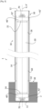
- the safety structure in addition to at least one hollow tube 10 provided with a longitudinal axis X and a free end 12 fixed in the base 2, comprises a shaft 20 housed inside the hollow tube 10 and cooperation means 30 between the hollow tube 10 and the shaft 20.
- the shaft 20 has a longitudinal axis X' substantially merging with the longitudinal axis X of the hollow tube 10. It is understood that the shaft 20 preferably has a radial dimension and a longitudinal dimension substantially smaller than the radial and longitudinal dimensions of the hollow tube 10 so as to be able to be easily housed inside the hollow tube 10 without protruding therefrom.
- the shaft 20 is furthermore made of a material of higher hardness than that of the material forming the hollow tube 10.
- the shaft 20 is in the form of a solid cylinder.
- the shaft 20 may be made of a metallic material or a metallic alloy, and advantageously a steel.
- the material forming the shaft 20 may have a Vickers hardness (HV) of between 40 and 70 kg f /mm 2 (kilogram-force per square millimeter), and advantageously between 60 and 65 kg f /mm 2 .
- a high hardness value improves the abrasion resistance of the steel.
- a Vickers hardness of at least 40 kg f /mm 2 is suitable.
- a maximum Vickers hardness of 70 kg f /mm 2 is suitable.
- the cooperation means 30 between the hollow tube 10 and the shaft 20 of the safety structure 1 are configured to allow the shaft 20 to rotate freely about its longitudinal axis X' and to retain the shaft 20 axially relative to the hollow tube 10.
- the cooperation means 30 comprise at least two parts: a first part to allow the shaft 20 to rotate freely about its longitudinal axis X' and a second part to retain the shaft 20 axially relative to the hollow tube 10. It is understood that the cooperation means 30 between the hollow tube 10 and the shaft 20 prevent the withdrawal of the shaft 20 by the free end 12 of the hollow tube 10.
- the first part of the cooperation means 30 comprises at each end 22, 24 of the shaft 20 at least one bearing 40 mounted on an external wall 26 of the shaft 20 and a ring 50 mounted on an external surface 42 of the bearing 40 and against an internal wall 14 of the hollow tube 10.
- the bearings 40 may be, without limitation, ball bearings, roller bearings, needle bearings or tapered bearings.
- Each ring 50 comprises an internal surface 52 configured to cooperate with the external surface 42 of the bearing 40.
- the internal surface 52 is configured to have a minimum of friction with the external surface 42. For this, the internal surface 52 of each ring 50 is bored.
- each ring 50 is tightly mounted with the hollow tube 10 so that the ring 50 cannot rotate inside the hollow tube 10.
- Each ring 50 may be secured to the shaft 20 with a bolt/washer assembly 70 so as to axially hold the bearing 40 between the shaft 20 and the ring 50.
- the rings 50 are made of a non-corrodible material so as to avoid blocking of the shaft 20 due to rust for example.
- the rings 50 may be made of plastic material such as polyamide 6-6 (PA66), polytetrafluoroethylene (PTFE) or made of metal such as titanium.
- FIG 3 shows another embodiment in which the first part of the cooperation means 30 comprises at least one bearing 40', different from the bearing 40.
- the bearing 40' is mounted on the external wall 26 of the shaft 20 and against the internal wall 14 of the hollow tube 10. In this way, an external surface 42' of the bearing 40' can be in contact with the internal wall 14 of the hollow tube 10. It is then understood that this bearing 40' has a radial dimension greater than the radial dimension of the shaft 20 and substantially less than or equal to the internal radial dimension of the hollow tube 10. In other words, in the case of a hollow tube 10 and a shaft 20 both cylindrical, the diameter of the bearing 40' is greater than that of the shaft 20 and substantially less than or equal to the internal diameter of the hollow tube 10.
- the second part of the cooperation means 30 comprises, in order to axially retain the shaft 20 relative to the hollow tube 10, at least one retaining means 32, 32' which extends radially. It is understood that this retaining means 32, 32' extends towards the inside of the hollow tube 10. In a non-limiting manner, this retaining means 32, 32' may be a stop formed by an annular groove on the hollow tube 10. Alternatively, the retaining means 32, 32' may be a circlip or a stop ring mounted against the hollow tube 10, and in particular against the internal wall 14 of the hollow tube 10. It is understood that at least one retaining means 32, 32' is located between the free end 12 of the hollow tube 10 and the other end 11 of the hollow tube fixed in the base 2.
- At least one retaining means 32, 32' is in contact with at least one of the rings 50 or at least one of the bearings 40'.
- a first retaining means 32 is located as close as possible to the base 2 while a second retaining means 32' is located on the side of the end 12, in particular between the first part of the cooperation means 30, we understand in contact with the ring 50 or the bearing 40', and the free end 12.
- the shaft 20 is retained on the one hand on the side of the free end 12 of the hollow tube 10 and on the other hand on the side of the base 2.
- the first retaining means 32 defined on the hollow tube 10 is located at the surface of the base 2, when the hollow tube 10 is fixed in the base 2.
- the free end 12 of the hollow tube 10 is closed by a plug, not shown, so as to protect access to the interior of the hollow tube 10 from the free end 12.
- the safety structure 1 comprises an annular space 60 defined by the external wall 26 of the shaft 20 and the internal wall 14 of the hollow tube 10.
- the safety structure 1 comprises, housed in the annular space 60, an intermediate body configured to increase the coefficient of friction between the shaft 20 and the blade of the cutting tool.
- an intermediate body configured to increase the coefficient of friction between the shaft 20 and the blade of the cutting tool.
- the intermediate body is made of a material chosen in a non-limiting manner from glass, ceramic, steel or wood, or a combination of the aforementioned materials. These materials in fact have the characteristic of increasing the coefficient of friction.
- the material making up the intermediate body is advantageously in particulate form, that is to say that it is in powder form or in the form of balls for example, and fills the annular space 60. In this way, the intermediate body does not prevent the rotation of the shaft 20 around its longitudinal axis X'.
- the intermediate body can be fixed directly to the shaft 20, for example in the form of a covering.
- FIG 4 illustrates an example of application of the security structure 1 as described in the above.
- the example presented here is a 100 comb turnstile. We understand that this “comb” is comparable to the security structure 1 described previously.
- a base 2 can be distinguished which is fixedly mounted and a base 3 which is configured to rotate along an axis of rotation coinciding with its longitudinal axis Y'.
- the latter comprises a fixed comb and at least one comb rotating around the longitudinal axis Y' of the base 3.
- the hollow tubes 10 of the different combs of the turnstile 100 are oriented horizontally, that is to say they are substantially parallel with the ground.
- safety structure 1 as described with vertically oriented hollow tubes 10, for example in a fencing application.
- cooperation means 30 between the hollow tube 10 and the shaft 20 prevent the withdrawal of the shaft 20 by the free end 12 of the hollow tube 10.
- step a a step consisting of mounting at least one bearing 40, 40' at each end 22, 24 of the shaft 20 can be carried out.
- a step consisting of mounting, at each end 22, 24 of the shaft 20, a ring 50, between the internal wall 14 of the hollow tube 10 and the external surface 42 of the bearing 40 can be carried out.
- the second part of the cooperation means 30 between the hollow tube 10 and the shaft 20 comprises at least one retaining means 32, 32' which extends radially relative to the hollow tube 10.
- the retaining means is produced by punching on the hollow tube 10.
- the retaining means is produced by inserting a circlip or a stop ring against the hollow tube 10.
- the second part of the cooperation means 30 between the hollow tube and the shaft 20 comprises a first retaining means 32 and a second retaining means 32'.
- the first retaining means 32 and the second means 32' can both be produced by punching on the hollow tube 10.
- the first retaining means 32 is produced by punching on the hollow tube 10 while the second retaining means 32' is produced by inserting a circlip or a stop ring against the hollow tube 10, in particular inside the hollow tube 10.
- an intermediate body can be inserted into the annular space 60 defined between the shaft 20 and the internal wall 14 of the hollow tube 10.
- the intermediate body is advantageously inserted while the shaft 20 is partially introduced into the hollow tube 10, that is to say before the end 22 of the shaft 20 is inserted inside the hollow tube 10.
- the intermediate body can be fixed around the shaft 20 before the shaft 20 is inserted into the hollow tube.
- the free end 12 of the hollow tube 10 is advantageously plugged using a stopper so as to protect access, from the free end 12, to the inside of the hollow tube 10, and in particular to the shaft 20.
- Another advantage is to improve the cutting resistance of the safety structure by making it difficult to use a cutting tool.
- the higher hardness of the shaft material compared to that of the hollow tube material causes heating and accelerated wear of the cutting tools.
- the attack point of the cutting tool will not be stable, which reduces its penetration force in the structure, increasing the time required to cut the structure.
- the intermediate body housed in the annular space allows to increase the heating of the cutting tools, contributing to a further improvement in cutting resistance.
- the safety structure according to the invention is suitable for countering all types of cutting tools, and in particular cutting tools of the grinder or chainsaw type which comprise rotating disks capable of rotating at high speed (between 4000 and 7000 rpm). Indeed, when bearings are mounted on the shaft, the latter can rotate at high speed.
- the manufacturing process of the safety structure is easy and quick to implement by inserting the shaft into the hollow tube and providing axial retention of the shaft.
- the process also has the advantage of being able to adapt to existing safety structures equipped with hollow tubes. This allows them to be reinforced on the one hand and allows for a reduction in infrastructure costs on the other.
Landscapes
- Engineering & Computer Science (AREA)
- Structural Engineering (AREA)
- Architecture (AREA)
- Civil Engineering (AREA)
- Emergency Lowering Means (AREA)
- Prostheses (AREA)
- Aiming, Guidance, Guns With A Light Source, Armor, Camouflage, And Targets (AREA)
- Devices Affording Protection Of Roads Or Walls For Sound Insulation (AREA)
- Shafts, Cranks, Connecting Bars, And Related Bearings (AREA)
- Road Signs Or Road Markings (AREA)
Claims (15)
- Sicherheitsstruktur (1), umfassend ueine Grundplatte (2, 3), die mit einer Längsachse (Y, Y') versehen ist, und mindestens:- ein hohles Rohr (10), das mit einer Längsachse (X) im Wesentlichen senkrecht zu der Längsachse (Y, Y') der Grundplatte (2, 3) versehen ist, mit einem in der Grundplatte (2, 3) befestigten Ende (11), wobei das hohle Rohr aus einem gegebenen Material gebildet ist,- eine Welle (20), die im Inneren des hohlen Rohrs (10) untergebracht ist und eine Längsachse (X') aufweist, die mit jener des hohlen Rohrs zusammenfällt, wobei die Welle außerdem aus einem Material mit höherer Härte als jene des Materials, das das hohle Rohr bildet, hergestellt ist,dadurch gekennzeichnet, dass sie weiter umfasst:- Eingriffsmittel (30) zwischen dem hohlen Rohr (10) und der Welle (20), die konfiguriert sind, um der Welle zu erlauben, frei um ihre Längsachse (X') herum zu drehen, und um die Welle bezüglich des hohlen Rohrs axial derart zurückzuhalten, um ihre Entnahme durch das freie Ende (12) zu verhindern.
- Sicherheitsstruktur (1) nach Anspruch 1, dadurch gekennzeichnet, dass die Eingriffsmittel (30) zwischen dem hohlen Rohr (10) und der Welle (20) zum axialen Zurückhalten der Welle bezüglich des hohlen Rohrs mindestens ein Rückhaltemittel (32, 32') umfassen, das sich radial erstreckt.
- Sicherheitsstruktur (1) nach Anspruch 2, dadurch gekennzeichnet, dass die Eingriffsmittel (30) zwischen dem hohlen Rohr (10) und der Welle (20), um der Welle zu erlauben, sich um ihre Längsachse (X') herum zu drehen, an jedem Ende (22, 24) der Welle Folgendes umfassen:- mindestens ein Lager (40), das an einer externen Wand (26) der Welle montiert ist,- einen Ring (50), der an einer externen Oberfläche (42) des Lagers (40) und gegen eine interne Wand (14) des hohlen Rohrs montiert ist.
- Sicherheitsstruktur (1) nach Anspruch 3, dadurch gekennzeichnet, dass das mindestens eine Rückhaltemittel (32, 32') in Kontakt mit mindestens einem der Ringe (50) und vorteilhafterweise auf der Seite des freien Endes (12) vorliegt.
- Sicherheitsstruktur (1) nach Anspruch 2, dadurch gekennzeichnet, dass die Eingriffsmittel (30) zwischen dem hohlen Rohr (10) und der Welle (20) an jedem Ende (22, 24) der Welle mindestens ein an einer externen Wand (26) der Welle und gegen eine interne Wand (14) des hohlen Rohrs montiertes Lager (40') umfassen, um der Welle zu erlauben, sich frei um ihre Längsachse (X') herum zu drehen.
- Sicherheitsstruktur (1) nach Anspruch 5, dadurch gekennzeichnet, dass das mindestens eine Rückhaltemittel (32, 32') in Kontakt mit mindestens einem der Lager (40') und vorteilhafterweise auf der Seite des freien Endes (12) vorliegt.
- Sicherheitsstruktur (1) nach einem der Ansprüche 3 oder 5, dadurch gekennzeichnet, dass ein erstes Rückhaltemittel (32) sich näher an der Grundplatte (2, 3) befindet und dass ein zweites Rückhaltemittel (32') sich auf der Seite des freien Endes (12) befindet.
- Sicherheitsstruktur (1) nach einem der Ansprüche 1 bis 7, dadurch gekennzeichnet, dass sie einen zwischenliegenden Körper umfasst, der in einem ringförmigen Raum (60) aufgenommen ist, der durch eine externe Wand (26) der Welle (20) und eine interne Wand (14) des hohlen Rohrs (10) definiert ist, wobei der zwischenliegende Körper konfiguriert ist, um den Reibungskoeffizienten zwischen der Welle (20) und einer Klinge eines Schneidwerkzeugs zu erhöhen.
- Sicherheitsstruktur (1) nach einem der Ansprüche 1 bis 8, dadurch gekennzeichnet, dass die Welle (20) aus einem metallischen Material oder einer metallischen Legierung besteht.
- Sicherheitsstruktur (1) nach Anspruch 9, dadurch gekennzeichnet, dass die Welle (20) aus Stahl mit einer Vickers-Härte zwischen 40 und 70 kgf/mm2, und vorzugsweise zwischen 60 und 65 kgf/mm2 besteht.
- Fertigungsverfahren einer Sicherheitsstruktur (1) nach einem der Ansprüche 1 bis 10, wobei das Verfahren mindestens die Schritte umfasst, bestehend aus:a) Einsetzen der Welle (20) in das Innere des hohlen Rohrs (10) durch sein freies Ende (12), wobei die Welle mit einem ersten Teil der Eingriffsmittel (30) mit dem hohlen Rohr versehen ist, wobei der erste Teil konfiguriert ist, um der Welle zu erlauben, sich frei um ihre Längsachse (X') zu drehen,b) Herstellen eines zweiten Teils der Eingriffsmittel (30) mit der Welle, wobei der zweite Teil konfiguriert ist, um die Welle axial bezüglich des hohlen Rohrs derart zurückzuhalten, um ihre Entnahme durch das freie Ende (12) zu verhindern.
- Verfahren nach Anspruch 11, wobei der zweite Teil der Eingriffsmittel (30) zwischen dem hohlen Rohr (10) und der Welle (20) mindestens ein Rückhaltemittel (32, 32') umfasst, dass sich radial erstreckt.
- Verfahren nach Anspruch 12, wobei das mindestens eine Rückhaltemittel durch Lochstanzen an dem hohlen Rohr hergestellt wird.
- Verfahren nach Anspruch 12, wobei das mindestens eine Rückhaltemittel durch Einsetzen eines Sprengrings oder eines Anschlagrings gegen das hohle Rohr (10) hergestellt wird.
- Verfahren nach der Kombination der Ansprüche 13 und 14, wobei der zweite Teil der Eingriffsmittel (30) zwischen dem hohlen Rohr (10) und der Welle (20) ein erstes Rückhaltemittel (32) und ein zweites Rückhaltemittel (32') umfasst, wobei das erste Rückhaltemittel (32) durch Lochstanzen an dem hohlen Rohr hergestellt wird und das zweite Rückhaltemittel (32') durch Einsetzen eines Sprengrings oder eines Anschlagrings gegen das hohle Rohr hergestellt wird.
Applications Claiming Priority (1)
| Application Number | Priority Date | Filing Date | Title |
|---|---|---|---|
| FR2201701A FR3133061B1 (fr) | 2022-02-25 | 2022-02-25 | Structure de sécurité renforcée |
Publications (3)
| Publication Number | Publication Date |
|---|---|
| EP4239155A1 EP4239155A1 (de) | 2023-09-06 |
| EP4239155B1 true EP4239155B1 (de) | 2025-01-22 |
| EP4239155C0 EP4239155C0 (de) | 2025-01-22 |
Family
ID=81648692
Family Applications (1)
| Application Number | Title | Priority Date | Filing Date |
|---|---|---|---|
| EP23158457.4A Active EP4239155B1 (de) | 2022-02-25 | 2023-02-24 | Verstärkte sicherheitsstruktur |
Country Status (3)
| Country | Link |
|---|---|
| EP (1) | EP4239155B1 (de) |
| ES (1) | ES3012060T3 (de) |
| FR (1) | FR3133061B1 (de) |
Family Cites Families (5)
| Publication number | Priority date | Publication date | Assignee | Title |
|---|---|---|---|---|
| US2125807A (en) * | 1938-03-19 | 1938-08-02 | Petty Zach Ansel | Bar |
| US4669239A (en) | 1986-02-12 | 1987-06-02 | The William Bayley Company | Security bars and barrier grids incorporating same |
| GB2240128A (en) | 1990-01-19 | 1991-07-24 | Frederick Richard Jones | Security bar |
| US7736085B2 (en) * | 2006-12-18 | 2010-06-15 | Neusch Innovations, Lp | Bollard system |
| US11268293B2 (en) * | 2017-05-30 | 2022-03-08 | Neusch Innovations, Lp | Bollard fence |
-
2022
- 2022-02-25 FR FR2201701A patent/FR3133061B1/fr active Active
-
2023
- 2023-02-24 ES ES23158457T patent/ES3012060T3/es active Active
- 2023-02-24 EP EP23158457.4A patent/EP4239155B1/de active Active
Also Published As
| Publication number | Publication date |
|---|---|
| ES3012060T3 (en) | 2025-04-08 |
| EP4239155C0 (de) | 2025-01-22 |
| EP4239155A1 (de) | 2023-09-06 |
| FR3133061A1 (fr) | 2023-09-01 |
| FR3133061B1 (fr) | 2024-05-03 |
Similar Documents
| Publication | Publication Date | Title |
|---|---|---|
| FR2640010A1 (fr) | Agencement pour la fixation d'une bague de roulement de grande durete dans la surface d'alesage de plus faible durete d'un logement ou sur la surface laterale de plus faible durete d'un arbre ou d'un organe analogue | |
| EP1884669B1 (de) | Blechkäfig und sphärisches Lager mit einem solchen Käfig | |
| EP2917969B1 (de) | Vorrichtung zum fixieren einer elektrischen anschlussklemme an einem träger | |
| FR2768271A1 (fr) | Procede de fabrication d'un rotor pour machine electrique rotative, rotor et machine concernes | |
| FR2524057A1 (fr) | Outil de forage a fraise rotative, et procede d'assemblage et de montage d'un element de coupe pour un tel outil | |
| FR3029586A1 (fr) | Dispositif de poulie | |
| FR3013087A1 (fr) | Roulement mecanique | |
| EP2110570A1 (de) | Verfahren zur Herstellung einer Rollvorrichtung | |
| EP4239155B1 (de) | Verstärkte sicherheitsstruktur | |
| FR2940379A1 (fr) | Douille a aiguilles a bague exterieure ayant une face cylindrique exterieure comportant un reseau d'elements en creux | |
| FR2955895A1 (fr) | Turbomachine avec agencement optimise pour la fixation d'un palier d'arbre tournant. boulon pour une telle turbomachine | |
| FR2494354A1 (fr) | Dispositif de fixation axe-ecrou | |
| FR2731248A3 (fr) | Dispositif de protection anti-percage pour des serrures a cylindre | |
| WO2011135209A2 (fr) | Assemblage instrumenté pour fusée d'essieu | |
| EP0566483A1 (de) | Schutzvorrichtung gegen Anbohren | |
| WO2019020944A1 (fr) | Ensemble de serrure de sécurité et de clé plate | |
| EP2564210A2 (de) | Instrumentierte baugruppe für ein achslager und montageverfahren dafür | |
| FR2628461A1 (fr) | Barre pour construction multidimensionnelle en treillis | |
| FR2986674A1 (fr) | Machine electrique et son procede de montage | |
| FR3057625B1 (fr) | Lanceur pour demarreur de vehicule automobile a moteur thermique | |
| FR3040749A1 (fr) | Systeme de roulement muni d'au moins une cage | |
| BE1032138B1 (fr) | Grille de sécurité pliable | |
| FR2568616A1 (fr) | Serrure de surete a protection renforcee contre l'effraction par percement. | |
| FR2470302A1 (fr) | Dispositif d'ancrage pour un cable toronne | |
| FR3105319A1 (fr) | Bague pour élément de liaison, élément de liaison et procédé de fabrication correspondant |
Legal Events
| Date | Code | Title | Description |
|---|---|---|---|
| PUAI | Public reference made under article 153(3) epc to a published international application that has entered the european phase |
Free format text: ORIGINAL CODE: 0009012 |
|
| STAA | Information on the status of an ep patent application or granted ep patent |
Free format text: STATUS: THE APPLICATION HAS BEEN PUBLISHED |
|
| AK | Designated contracting states |
Kind code of ref document: A1 Designated state(s): AL AT BE BG CH CY CZ DE DK EE ES FI FR GB GR HR HU IE IS IT LI LT LU LV MC ME MK MT NL NO PL PT RO RS SE SI SK SM TR |
|
| STAA | Information on the status of an ep patent application or granted ep patent |
Free format text: STATUS: REQUEST FOR EXAMINATION WAS MADE |
|
| 17P | Request for examination filed |
Effective date: 20240305 |
|
| RBV | Designated contracting states (corrected) |
Designated state(s): AL AT BE BG CH CY CZ DE DK EE ES FI FR GB GR HR HU IE IS IT LI LT LU LV MC ME MK MT NL NO PL PT RO RS SE SI SK SM TR |
|
| GRAP | Despatch of communication of intention to grant a patent |
Free format text: ORIGINAL CODE: EPIDOSNIGR1 |
|
| STAA | Information on the status of an ep patent application or granted ep patent |
Free format text: STATUS: GRANT OF PATENT IS INTENDED |
|
| RIC1 | Information provided on ipc code assigned before grant |
Ipc: E04H 17/14 20060101ALI20240724BHEP Ipc: E06B 11/08 20060101ALI20240724BHEP Ipc: E06B 9/01 20060101AFI20240724BHEP |
|
| INTG | Intention to grant announced |
Effective date: 20240806 |
|
| GRAS | Grant fee paid |
Free format text: ORIGINAL CODE: EPIDOSNIGR3 |
|
| GRAA | (expected) grant |
Free format text: ORIGINAL CODE: 0009210 |
|
| STAA | Information on the status of an ep patent application or granted ep patent |
Free format text: STATUS: THE PATENT HAS BEEN GRANTED |
|
| AK | Designated contracting states |
Kind code of ref document: B1 Designated state(s): AL AT BE BG CH CY CZ DE DK EE ES FI FR GB GR HR HU IE IS IT LI LT LU LV MC ME MK MT NL NO PL PT RO RS SE SI SK SM TR |
|
| REG | Reference to a national code |
Ref country code: GB Ref legal event code: FG4D Free format text: NOT ENGLISH |
|
| REG | Reference to a national code |
Ref country code: CH Ref legal event code: EP |
|
| REG | Reference to a national code |
Ref country code: IE Ref legal event code: FG4D Free format text: LANGUAGE OF EP DOCUMENT: FRENCH |
|
| REG | Reference to a national code |
Ref country code: DE Ref legal event code: R096 Ref document number: 602023001722 Country of ref document: DE |
|
| U01 | Request for unitary effect filed |
Effective date: 20250130 |
|
| U07 | Unitary effect registered |
Designated state(s): AT BE BG DE DK EE FI FR IT LT LU LV MT NL PT RO SE SI Effective date: 20250205 |
|
| U20 | Renewal fee for the european patent with unitary effect paid |
Year of fee payment: 3 Effective date: 20250220 |
|
| REG | Reference to a national code |
Ref country code: ES Ref legal event code: FG2A Ref document number: 3012060 Country of ref document: ES Kind code of ref document: T3 Effective date: 20250408 |
|
| PG25 | Lapsed in a contracting state [announced via postgrant information from national office to epo] |
Ref country code: RS Free format text: LAPSE BECAUSE OF FAILURE TO SUBMIT A TRANSLATION OF THE DESCRIPTION OR TO PAY THE FEE WITHIN THE PRESCRIBED TIME-LIMIT Effective date: 20250422 |
|
| PG25 | Lapsed in a contracting state [announced via postgrant information from national office to epo] |
Ref country code: PL Free format text: LAPSE BECAUSE OF FAILURE TO SUBMIT A TRANSLATION OF THE DESCRIPTION OR TO PAY THE FEE WITHIN THE PRESCRIBED TIME-LIMIT Effective date: 20250122 |
|
| PGFP | Annual fee paid to national office [announced via postgrant information from national office to epo] |
Ref country code: ES Payment date: 20250331 Year of fee payment: 3 |
|
| PG25 | Lapsed in a contracting state [announced via postgrant information from national office to epo] |
Ref country code: IS Free format text: LAPSE BECAUSE OF FAILURE TO SUBMIT A TRANSLATION OF THE DESCRIPTION OR TO PAY THE FEE WITHIN THE PRESCRIBED TIME-LIMIT Effective date: 20250522 Ref country code: NO Free format text: LAPSE BECAUSE OF FAILURE TO SUBMIT A TRANSLATION OF THE DESCRIPTION OR TO PAY THE FEE WITHIN THE PRESCRIBED TIME-LIMIT Effective date: 20250422 |
|
| PG25 | Lapsed in a contracting state [announced via postgrant information from national office to epo] |
Ref country code: HR Free format text: LAPSE BECAUSE OF FAILURE TO SUBMIT A TRANSLATION OF THE DESCRIPTION OR TO PAY THE FEE WITHIN THE PRESCRIBED TIME-LIMIT Effective date: 20250122 |
|
| PG25 | Lapsed in a contracting state [announced via postgrant information from national office to epo] |
Ref country code: GR Free format text: LAPSE BECAUSE OF FAILURE TO SUBMIT A TRANSLATION OF THE DESCRIPTION OR TO PAY THE FEE WITHIN THE PRESCRIBED TIME-LIMIT Effective date: 20250423 |
|
| PG25 | Lapsed in a contracting state [announced via postgrant information from national office to epo] |
Ref country code: SM Free format text: LAPSE BECAUSE OF FAILURE TO SUBMIT A TRANSLATION OF THE DESCRIPTION OR TO PAY THE FEE WITHIN THE PRESCRIBED TIME-LIMIT Effective date: 20250122 |
|
| PG25 | Lapsed in a contracting state [announced via postgrant information from national office to epo] |
Ref country code: MC Free format text: LAPSE BECAUSE OF FAILURE TO SUBMIT A TRANSLATION OF THE DESCRIPTION OR TO PAY THE FEE WITHIN THE PRESCRIBED TIME-LIMIT Effective date: 20250122 |
|
| PG25 | Lapsed in a contracting state [announced via postgrant information from national office to epo] |
Ref country code: CZ Free format text: LAPSE BECAUSE OF FAILURE TO SUBMIT A TRANSLATION OF THE DESCRIPTION OR TO PAY THE FEE WITHIN THE PRESCRIBED TIME-LIMIT Effective date: 20250122 |
|
| PG25 | Lapsed in a contracting state [announced via postgrant information from national office to epo] |
Ref country code: SK Free format text: LAPSE BECAUSE OF FAILURE TO SUBMIT A TRANSLATION OF THE DESCRIPTION OR TO PAY THE FEE WITHIN THE PRESCRIBED TIME-LIMIT Effective date: 20250122 |
|
| PLBE | No opposition filed within time limit |
Free format text: ORIGINAL CODE: 0009261 |
|
| STAA | Information on the status of an ep patent application or granted ep patent |
Free format text: STATUS: NO OPPOSITION FILED WITHIN TIME LIMIT |
|
| REG | Reference to a national code |
Ref country code: CH Ref legal event code: L10 Free format text: ST27 STATUS EVENT CODE: U-0-0-L10-L00 (AS PROVIDED BY THE NATIONAL OFFICE) Effective date: 20251203 |
|
| 26N | No opposition filed |
Effective date: 20251023 |
|
| PG25 | Lapsed in a contracting state [announced via postgrant information from national office to epo] |
Ref country code: IE Free format text: LAPSE BECAUSE OF NON-PAYMENT OF DUE FEES Effective date: 20250224 |
|
| U20 | Renewal fee for the european patent with unitary effect paid |
Year of fee payment: 4 Effective date: 20260106 |
|
| REG | Reference to a national code |
Ref country code: CH Ref legal event code: U11 Free format text: ST27 STATUS EVENT CODE: U-0-0-U10-U11 (AS PROVIDED BY THE NATIONAL OFFICE) Effective date: 20260301 |