EP4238784B1 - Reifen - Google Patents
Reifen Download PDFInfo
- Publication number
- EP4238784B1 EP4238784B1 EP23152423.2A EP23152423A EP4238784B1 EP 4238784 B1 EP4238784 B1 EP 4238784B1 EP 23152423 A EP23152423 A EP 23152423A EP 4238784 B1 EP4238784 B1 EP 4238784B1
- Authority
- EP
- European Patent Office
- Prior art keywords
- tire
- sipe
- offset
- elements
- circumferential direction
- Prior art date
- Legal status (The legal status is an assumption and is not a legal conclusion. Google has not performed a legal analysis and makes no representation as to the accuracy of the status listed.)
- Active
Links
Images


Classifications
-
- B—PERFORMING OPERATIONS; TRANSPORTING
- B60—VEHICLES IN GENERAL
- B60C—VEHICLE TYRES; TYRE INFLATION; TYRE CHANGING; CONNECTING VALVES TO INFLATABLE ELASTIC BODIES IN GENERAL; DEVICES OR ARRANGEMENTS RELATED TO TYRES
- B60C11/00—Tyre tread bands; Tread patterns; Anti-skid inserts
- B60C11/03—Tread patterns
- B60C11/12—Tread patterns characterised by the use of narrow slits or incisions, e.g. sipes
- B60C11/1204—Tread patterns characterised by the use of narrow slits or incisions, e.g. sipes with special shape of the sipe
- B60C11/1218—Three-dimensional shape with regard to depth and extending direction
-
- B—PERFORMING OPERATIONS; TRANSPORTING
- B60—VEHICLES IN GENERAL
- B60C—VEHICLE TYRES; TYRE INFLATION; TYRE CHANGING; CONNECTING VALVES TO INFLATABLE ELASTIC BODIES IN GENERAL; DEVICES OR ARRANGEMENTS RELATED TO TYRES
- B60C11/00—Tyre tread bands; Tread patterns; Anti-skid inserts
- B60C11/03—Tread patterns
- B60C11/12—Tread patterns characterised by the use of narrow slits or incisions, e.g. sipes
- B60C11/1204—Tread patterns characterised by the use of narrow slits or incisions, e.g. sipes with special shape of the sipe
- B60C2011/1209—Tread patterns characterised by the use of narrow slits or incisions, e.g. sipes with special shape of the sipe straight at the tread surface
Definitions
- the present invention relates to a tire having a tread portion.
- a tire in which, at an inner edge of a sipe main portion in the tire radial direction, a first inclined portion that is connected to the inner edge, and extends to the bottom of the sipe so as to be inclined toward one side relative to the center line of the sipe main portion which extends in the depth direction, and a second inclined portion that extends so as to be inclined toward the other side relative thereto are alternately disposed in the length direction of the sipe, has been suggested (for example, see Japanese Laid-Open Patent Publication No. 2000-238513 ).
- stiffness of a land portion becomes high according to a tread portion being worn. Therefore, an edge effect of the sipe becomes low, and on-ice/snow performance and wet performance are affected.
- the sipe disclosed in Japanese Laid-Open Patent Publication No. 2000-238513 does not include a component extending in the tire circumferential direction (see FIGS. 1 , 2 , and the like). Accordingly, stiffness of the land portion in the tire axial direction cannot be inhibited from becoming high according to the tread portion being worn. Therefore, the edge effect of an end edge of a block during cornering becomes low according to progress of wear of the tread portion. Furthermore, the edge effect of the sipe itself cannot be expected, so that on-ice/snow performance and wet performance during cornering are degraded.
- Document EP 1 533 141 A1 discloses a tire according to the preamble of claim 1.
- a main object of the present invention is to provide a tire capable of maintaining excellent cornering performance on an ice/snow road surface and a wet road surface even if wear of a tread portion progresses.
- the object is achieved by the subject-matter of independent claim 1.
- Advantageous further developments are laid out in the dependent claims.
- the present invention is directed to a tire including a tread portion.
- the tread portion includes at least one land portion.
- the land portion includes an outer region disposed inwardly of a tread surface in a tire radial direction, an inner region disposed inwardly of the outer region in the tire radial direction, and at least one sipe.
- the at least one sipe includes one outer sipe element extending in the outer region in a tire axial direction, and a plurality of inner sipe elements extending in the inner region.
- the plurality of inner sipe elements includes a component extending in a tire circumferential direction, and is connected to the outer sipe element.
- the plurality of inner sipe elements comprises a plurality of bent elements, and each of the plurality of bent elements comprises a first offset element that is offset toward one side relative to the outer sipe element in the tire circumferential direction and that extends in the tire axial direction, and a second offset element that is offset toward another side relative to the outer sipe element in the tire circumferential direction and that extends in the tire axial direction, wherein each of the plurality of bent elements comprises a joint element connecting between at least one of the first offset elements and at least one of the second offset elements.
- the first offset element comprises a first terminating element extending toward the second offset element so as to be inclined relative to the tire circumferential direction in a direction opposite to a direction of the joint element, at an end portion on a side opposite to a side connecting to the joint element
- the second offset element comprises a second terminating element extending toward the first offset element so as to be inclined relative to the tire circumferential direction in a direction opposite to the direction of the joint element, at an end portion on a side opposite to a side connecting to the joint element.
- bent elements adjacent to each other in the tire circumferential direction partially overlap each other in the tire axial direction.
- the sipe includes one outer sipe element extending in the outer region in the tire axial direction, and the plurality of inner sipe elements extending in the inner region, and the plurality of inner sipe elements includes the component extending in the tire circumferential direction. Therefore, the component extending in the tire circumferential direction in the inner sipe element appears according to progress of wear. Thus, stiffness of the land portion in the tire axial direction is inhibited from becoming high, and excellent cornering performance on an ice/snow road surface and a wet road surface is maintained. Furthermore, an edge effect of the inner sipe element itself allows excellent cornering performance on an ice/snow road surface and a wet road surface to be obtained.
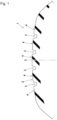
- FIG. 1 is a transverse cross-sectional view of a tread portion 2 of a tire 1 according to the present embodiment.
- FIG. 1 is a cross-sectional view of the tire 1 in a standardized state, including the tire rotation axis.
- the tread portion 2 is preferably used for, for example, a pneumatic tire.
- the tread portion 2 is not limited to such usage.
- the tread portion 2 may be used for, for example, an airless tire.
- the "standardized state” represents a state where the tire is mounted on a standardized rim and is inflated to a standardized internal pressure, and no load is applied to the tire.
- the standardized state represents a standard use state corresponding to a purpose of use of the tire under no load.
- the dimensions and the like of components of the tire are represented by values measured in the standardized state. An ordinary tolerance for a rubber molded product is allowed for each component described herein.
- the "standardized rim” represents a rim that is defined by the standard for each tire, and is, for example, the "standardized rim” in the JATMA standard, the "Design Rim” in the TRA standard, or the “Measuring Rim” in the ETRTO standard.
- the "standardized internal pressure” represents an air pressure that is defined by the standard for each tire, and is the “maximum air pressure” in the JATMA standard, the maximum value recited in the table "TIRE LOAD LIMITS AT VARIOUS COLD INFLATION PRESSURES" in the TRA standard, or the "INFLATION PRESSURE” in the ETRTO standard.
- the tread portion 2 includes, for example, a plurality of main grooves 3 that continuously extends in the tire circumferential direction, and a plurality of land portions 4 demarcated by the main grooves 3.
- the tread portion 2 may be formed by a single land portion 4 without having the main grooves 3 formed in the tread portion 2.
- the land portion 4 is formed as, for example, a block array including a plurality of blocks in the tire circumferential direction.
- the block is demarcated between a plurality of lateral grooves extending across the land portion 4 in the tire axial direction.
- the land portion 4 is not limited to such a structure, and may be, for example, formed in a rib-like shape that continuously extends in the tire circumferential direction.
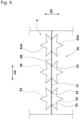
- FIG. 2 shows a cross-section obtained by cutting the land portion 4 in a tire circumferential direction DC.
- the land portion 4 includes an outer region 41 and an inner region 42.
- the outer region 41 is a region extending inwardly in the tire radial direction from a tread surface 40 over a first distance (depth) D1.
- the inner region 42 is disposed inwardly of the outer region 41 in the tire radial direction.
- a boundary 43 between the outer region 41 and the inner region 42 is distant from the tread surface 40 over the first distance D1 in the tire radially inward direction.
- the land portion 4 includes at least one sipe 5.
- the "sipe” represents a cut portion having a small width, and a width between two sipe walls opposing each other is not greater than 1.5 mm.
- An edge effect is exhibited by an edge at which the tread surface 40 and the sipe wall intersect each other to particularly enhance on-ice/snow performance and wet performance of the tire 1.
- the sipe 5 includes one outer sipe element 51 extending in the outer region 41 in the tire axial direction, and a plurality of inner sipe elements 52 extending in the inner region 42.
- a plurality of the sipes 5 each of which includes the outer sipe element 51 and the inner sipe elements 52 having such structures is preferably disposed in each of the land portions 4.
- the number of the sipes 5 formed in the land portion 4 may be at least one.
- each of the land portions 4 may include the sipe 5 and a sipe having a form other than the form of the sipe 5.
- the plurality of inner sipe elements 52 is formed on the inner side in the tire radial direction so as to diverge from the outer sipe element 51 at the boundary 43 between the outer region 41 and the inner region 42. That is, the plurality of inner sipe elements 52 is connected to the outer sipe element 51 at the boundary 43.
- the inner sipe element 52 includes a component 52A extending in the tire circumferential direction DC.
- the "component extending in the tire circumferential direction DC” represents a component that is inclined relative to the tire axial direction or a component extending orthogonal to the tire axial direction, that is, a component that is not parallel to the tire axial direction.
- the component 52A extending in the tire circumferential direction DC in the inner sipe element 52 appears at the tread surface 40 according to progress of wear.
- stiffness of the land portion 4 in the tire axial direction is inhibited from becoming high, to maintain excellent cornering performance on an ice/snow road surface and a wet road surface.
- edge effect exhibited by the component 52A itself of the inner sipe element 52 excellent cornering performance on an ice/snow road surface and a wet road surface is expected.
- an angle of the component 52A relative to the tire axial direction is preferably not less than 45°.
- the component 52A is preferably not parallel to the outer sipe element 51.
- a plurality of the inner sipe elements 52 having forms different from that of the outer sipe element 51 appears according to progress of wear, so that the degree of freedom of the inner sipe element 52 is enhanced, and more excellent cornering performance on an ice/snow road surface and a wet road surface is obtained.
- the component 52A is preferably increased toward the inner side in the tire radial direction.
- the component 52A appearing at the tread surface 40 is increased according to progress of wear, so that more excellent cornering performance on an ice/snow road surface and a wet road surface is obtained from the intermediate stage of wear to the end stage of wear.
- FIG. 3 is a development of the land portion 4 of a tire not being part of the present invention and illustrates a sipe 5A as one form of the sipe 5.
- the outer sipe element 51 is indicated by a solid line
- the inner sipe element 52 is indicated by a dashed line.
- the sipe 5A is formed as a so-called open sipe that reaches both ends of the land portion 4 in a tire axial direction DA.
- the sipe 5A may be formed as a so-called semi-open sipe that reaches one end of the land portion 4 in the tire axial direction DA, or formed as a so-called closed sipe having both ends in the tire axial direction DA inside the land portion 4.
- sipes 5B and 5C described below.
- the plurality of inner sipe elements 52 includes an element 54 extending from an originating point 53 connected to the outer sipe element 51 so as to be coplanar with the outer sipe element 51, and elements 55 that are extended in a radial manner from the originating point 53 connected to the outer sipe element 51.
- the sipe 5A having such a structure allows the component 52A extending in the tire circumferential direction DC relative to the element 54 to be increased from the intermediate stage of wear to the end stage of wear, and excellent cornering performance on an ice/snow road surface and a wet road surface is expected.
- the plurality of inner sipe elements 52 includes a closed element 56 formed so as to go around from the originating point 53 connected to the outer sipe element 51.
- the sipe 5B having such a structure allows the component 52A extending in the tire circumferential direction DC in the element 56 to be increased from the intermediate stage of wear to the end stage of wear, and excellent cornering performance on an ice/snow road surface and a wet road surface is expected.
- the element 56 is preferably formed in a polygonal shape (dodecagon in FIG. 4 ) as viewed in the tire radial direction.
- the polygonal shape may be a star-like shape that has interior angles such that acute angles and obtuse angles alternate.
- the sipe 5B having such a structure allows the component 52A extending in the tire circumferential direction DC in the element 56 to be further increased from the intermediate stage of wear to the end stage of wear.
- the plurality of inner sipe elements 52 may be separate from each other, or may be connected to each other through the element 54 (see FIG. 3 ) extending so as to be coplanar with the outer sipe element 51.
- both the sipe 5A and the sipe 5B may be formed in one land portion 4.
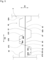
- FIG. 5 is a development of the land portion 4 and illustrates a sipe 5C as still another form of the sipe 5.
- the outer sipe element 51 is indicated by a solid line
- the inner sipe element 52 is indicated by a dashed line.
- the plurality of inner sipe elements 52 includes a plurality of bent elements 57.
- the plurality of bent elements 57 each include a first offset element 57A, a second offset element 57B, and a joint element 57C.
- the first offset element 57A is offset toward one side relative to the outer sipe element 51 in the tire circumferential direction DC, and extends in the tire axial direction DA.
- the second offset element 57B is offset toward the other side relative to the outer sipe element 51 in the tire circumferential direction DC, and extends in the tire axial direction DA.
- the first offset element 57A and the second offset element 57B are offset in opposite sides, respectively, in the tire circumferential direction DC.
- the joint element 57C connects between the first offset element 57A and the second offset element 57B.
- the joint element 57C extends from one side toward the other side in the tire circumferential direction DC, and forms the component 52A extending in the tire circumferential direction DC in the bent element 57.
- the bent element 57 including the joint element 57C as the component 52A extending in the tire circumferential direction DC allows excellent cornering performance on an ice/snow road surface and a wet road surface to be obtained from the intermediate stage of wear to the end stage of wear.
- the plurality of bent elements 57 are separate from each other. Thus, stiffness of the land portion 4 is inhibited from becoming excessively low, and excellent steering stability on a dry road surface is obtained.
- the joint element 57C is preferably inclined relative to the tire circumferential direction DC.
- the joint element 57C having such a structure forms a component 52B extending in the tire axial direction DA in the inner sipe element 52.
- the first offset element 57A preferably includes a first terminating element 57D, at an end portion on the side opposite to the side connecting to the joint element 57C.
- the first terminating element 57D extends toward the second offset element 57B of the adjacent bent element 57.
- the first terminating element 57D extends so as to be inclined relative to the tire circumferential direction DC in the direction opposite to the direction of the joint element 57C.
- the first terminating element 57D having such a structure forms a key-like shape together with the first offset element 57A and the joint element 57C, and an excellent edge effect is exhibited and excellent acceleration/deceleration performance and cornering performance on an ice/snow road surface and a wet road surface are obtained from the intermediate stage of wear to the end stage of wear.
- the second offset element 57B preferably includes a second terminating element 57E, at an end portion on the side opposite to the side connecting to the joint element 57C.
- the second terminating element 57E extends toward the first offset element 57A of the adjacent bent element 57.
- the second terminating element 57E extends so as to be inclined relative to the tire circumferential direction DC in the direction opposite to the direction of the joint element 57C.
- the second terminating element 57E having such a structure forms a key-like shape together with the second offset element 57B and the joint element 57C, and an excellent edge effect is exhibited and excellent acceleration/deceleration performance and cornering performance on an ice/snow road surface and a wet road surface are obtained from the intermediate stage of wear to the end stage of wear.
- the bent elements 57 adjacent to each other in the tire circumferential direction DC partially overlap each other in the tire axial direction DA.
- a part of the first offset element 57A and the first terminating element 57D, and a part of the second offset element 57B and the second terminating element 57E overlap each other in the tire axial direction DA.
- the bent elements 57 having such a structure allow the density of the bent elements 57 to be locally increased, and excellent acceleration/deceleration performance on an ice/snow road surface and a wet road surface is obtained from the intermediate stage of wear to the end stage of wear.
- FIGS. 6 and 7 are each a perspective view of the sipe 5C as viewed through the land portion 4.
- the contour of the land portion 4 is indicated by an alternate long and two short dashes line
- the contour of the sipe 5C is indicated by a solid line.
- the first offset element 57A has an inclined element 58A that is inclined relative to a tire radial direction DR.
- the second offset element 57B has an inclined element 58B that is inclined relative to the tire radial direction DR.
- the joint element 57C, the first terminating element 57D, and the second terminating element 57E have inclined elements 58C, 58D, and 58E, respectively, which are inclined relative to the tire radial direction DR.
- the inclined elements 58A, 58B, 58C, 58D, and 58E are disposed on the outer side in the tire radial direction DR in the inner sipe element 52, and are connected to the outer sipe element 51.
- the inclined elements 58A, 58B allow the offsets of the first offset element 57A and the second offset element 57B to be increased according to progress of wear, and allow a distance between the first offset element 57A and the second offset element 57B to be increased.
- the inclined elements 58C, 58D, and 58E allow the lengths of the joint element 57C, the first terminating element 57D, and the second terminating element 57E to be increased according to progress of wear.
- the component 52A extending in the tire circumferential direction DC in the inner sipe element 52 is increased, and excellent cornering performance on an ice/snow road surface and a wet road surface is obtained from the intermediate stage of wear to the end stage of wear.
- the first offset element 57A has a parallel element 59A that is bent from the inclined element 58A and is parallel to the tire radial direction DR.
- the second offset element 57B has a parallel element 59B that is bent from the inclined element 58B and is parallel to the tire radial direction DR.
- the joint element 57C, the first terminating element 57D, and the second terminating element 57E have parallel elements 59C, 59D, and 59E that are parallel to the tire radial direction DR.
- the parallel elements 59A, 59B, 59C, 59D, and 59E are disposed on the inner side in the tire radial direction DR in the inner sipe element 52, and are connected to the inclined elements 58A, 58B, 58C, 58D, and 58E, respectively.
- the tread portion 2 can be easily demolded from a vulcanization mold after the tire 1 has been vulcanized and molded while a sufficient depth of the inner sipe element 52 is assured.
- damage to a blade disposed in a vulcanization mold for forming the sipe 5C and rubber of the tread portion 2 is reduced.
- a ratio X/Y of the total X of the lengths of the components 52A extending in the tire circumferential direction DC, relative to the total Y of the lengths of the components 52B extending in the tire axial direction DA is preferably 0.3 to 0.7.
- the length of the component 52B extending in the tire axial direction DA and the length of the component 52A extending in the tire circumferential direction DC are each measured at the inner ends, in the tire radial direction DR, of the inclined elements 58A, 58B, 58C, 58D, and 58E.
- an angle ⁇ AD between the first offset element 57A and the first terminating element 57D is preferably 90° to 130°.
- the inner sipe element 52 having a key-like shape is formed by the first terminating element 57D, the first offset element 57A, and the joint element 57C, and excellent acceleration/deceleration performance and cornering performance on an ice/snow road surface and a wet road surface are obtained at and after the intermediate stage of wear.
- a distance between the first terminating element 57D and the second terminating element 57E opposing each other is sufficiently obtained, and sufficient stiffness, in the tire axial direction DA, of the land portion 4 is assured from the intermediate stage of wear to the end stage of wear.
- the angle ⁇ AD is not greater than 130°, the component 52A extending in the tire circumferential direction DC in the first terminating element 57D is easily increased.
- an angle ⁇ BE between the second offset element 57B and the second terminating element 57E is preferably 90° to 130°.
- Each of an angle ⁇ AC between the first offset element 57A and the joint element 57C, and an angle ⁇ BC between the second offset element 57B and the joint element 57C is preferably 90° to 130°.
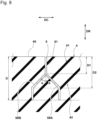
- FIG. 8 shows a cross-section obtained by cutting the land portion 4 including the sipe 5C in the tire circumferential direction DC.
- a ratio D1/D of a depth D1 of the outer region 41 from the tread surface 40, relative to the entire depth D of the sipe 5C is preferably not greater than 20%.
- the inner sipe element 52 diverging from the outer region 41 appears early at the tread surface 40, and excellent cornering performance and acceleration/deceleration performance on an ice/snow road surface and a wet road surface are obtained.
- a ratio D2/D of a depth D2 of each of the inclined elements 58A, 58B, 58C, 58D, and 58E from the tread surface 40, relative to the entire depth D of the sipe 5C is preferably not greater than 95%.
- a distance between the first offset element 57A and the second offset element 57B is increased at the end stage of wear, and the length of each of the joint element 57C, the first terminating element 57D, and the second terminating element 57E is increased.
- the component 52A extending in the tire circumferential direction DC in the inner sipe element 52 is increased, and excellent cornering performance on an ice/snow road surface and a wet road surface is obtained at the end stage of wear.
- An angle ⁇ of each of the inclined elements 58A, 58B, 58C, 58D, and 58E relative to the tire radial direction DR is preferably not greater than 45°. In a case where the angle ⁇ is not greater than 45°, a distance between the parallel elements 59A and 59B is inhibited from being excessively increased, and the number of the sipes 5C can be increased in the tire circumferential direction DC.
- the angle ⁇ is greater than 0°.
Landscapes
- Engineering & Computer Science (AREA)
- Mechanical Engineering (AREA)
- Tires In General (AREA)
Claims (7)
- Reifen (1) miteinem Laufflächenabschnitt (2),wobei der Laufflächenabschnitt (2) mindestens einen Stegabschnitt (4) umfasst, wobei der Stegabschnitt (4) einen äußeren Bereich (41), der in einer Reifenradialrichtung (DR) innerhalb einer Lauffläche (40) angeordnet ist, einen inneren Bereich (42), der in der Reifenradialrichtung (DR) innerhalb des äußeren Bereichs (41) angeordnet ist, und mindestens eine Lamelle (5) umfasst,wobei die mindestens eine Lamelle (5) ein äußeres Lamellenelement (51), das sich in dem äußeren Bereich (41) in einer Reifenaxialrichtung (DA) erstreckt, und eine Vielzahl von inneren Lamellenelementen (52) umfasst, die sich in dem inneren Bereich (42) erstrecken, undwobei die Vielzahl von inneren Lamellenelementen (52) eine Komponente (52A) umfasst, die sich in einer Reifenumfangsrichtung (DC) erstreckt und mit dem äußeren Lamellenelement (51) verbunden ist,wobei die Vielzahl von inneren Lamellenelementen (52) eine Vielzahl von gebogenen Elementen (57) umfasst, undwobei jedes der Vielzahl von gebogenen Elementen (57) ein erstes versetztes Element (57A), das in Richtung einer Seite relativ zu dem äußeren Lamellenelement (51) in der Reifenumfangsrichtung (DC) versetzt ist und sich in der Reifenaxialrichtung (DA) erstreckt, undein zweites versetztes Element (57B) umfasst, das in Richtung einer anderen Seite relativ zu dem äußeren Lamellenelement (51) in der Reifenumfangsrichtung (DC) versetzt ist und sich in der Reifenaxialrichtung (DA) erstreckt, wobeijedes der mehreren gebogenen Elemente (57) ein Verbindungselement (57C) umfasst, das mindestens eines der ersten versetzten Elemente (57A) und mindestens eines der zweiten versetzten Elemente (57B) verbindet, dadurch gekennzeichnet, dassin jedem der mehreren gebogenen Elemente (57)das erste versetzte Element (57A) ein erstes Abschlusselement (57D) umfasst, das sich in Richtung des zweiten versetzten Elements (57B) erstreckt, so dass es an einem Endabschnitt auf einer Seite, die einer mit dem Verbindungselement (57C) verbundenen Seite gegenüberliegt, relativ zur Reifenumfangsrichtung (DC) in einer Richtung geneigt ist, die entgegengesetzt zu einer Richtung des Verbindungselements (57C) ist,das zweite versetzte Element (57B) ein zweites Abschlusselement (57E) umfasst, das sich in Richtung des ersten versetzten Elements (57A) erstreckt, so dass es an einem Endabschnitt auf einer Seite, die einer mit dem Verbindungselement (57C) verbundenen Seite gegenüberliegt, relativ zur Reifenumfangsrichtung (DC) in einer Richtung geneigt ist, die entgegengesetzt zur Richtung des Verbindungselements (57C) ist, undsich unter den mehreren gebogenen Elementen (57) in der Reifenumfangsrichtung (DC) benachbarte gebogene Elemente (57) einander teilweise in der Reifenaxialrichtung (DA) überlappen.
- Reifen (1) nach Anspruch 1, wobei die sich in der Reifenumfangsrichtung (DC) erstreckende Komponente (52A) nicht parallel zu dem äußeren Lamellenelement (51) ist.
- Reifen (1) nach Anspruch 1 oder 2, wobei eine Verlängerung in der Reifenumfangsrichtung (DC) der Komponente (52A) in Richtung einer Innenseite in der Reifenradialrichtung (DR) vergrößert ist.
- Reifen (1) nach einem der Ansprüche 1 bis 3, wobei das Verbindungselement (57C) relativ zur Reifenumfangsrichtung (DC) geneigt ist.
- Reifen (1) nach einem der Ansprüche 1 bis 4, wobei das erste versetzte Element (57A) und das zweite versetzte Element (57B) jeweils ein geneigtes Element (58A, 58B) aufweisen, das relativ zur Reifenradialrichtung (DR) geneigt ist.
- Reifen (1) nach Anspruch 5, wobei das erste versetzte Element (57A) und das zweite versetzte Element (57B) jeweils ein paralleles Element (59A, 59B) aufweisen, das von dem geneigten Element (58A, 58B) gebogen ist und parallel zur Reifenradialrichtung (DR) verläuft.
- Reifen (1) nach Anspruch 5 oder 6, wobei an einem inneren Ende des geneigten Elements (58A, 58B) in der Reifenradialrichtung (DR) ein Verhältnis X/Y einer Summe X von Längen der Komponenten (52A), die sich in der Reifenumfangsrichtung (DC) erstrecken, zu einer Summe Y von Längen der Komponenten (52B), die sich in der Reifenaxialrichtung (DA) erstrecken, 0,3 bis 0,7 beträgt.
Applications Claiming Priority (1)
| Application Number | Priority Date | Filing Date | Title |
|---|---|---|---|
| JP2022032017A JP7838316B2 (ja) | 2022-03-02 | タイヤ |
Publications (2)
| Publication Number | Publication Date |
|---|---|
| EP4238784A1 EP4238784A1 (de) | 2023-09-06 |
| EP4238784B1 true EP4238784B1 (de) | 2025-01-15 |
Family
ID=85018352
Family Applications (1)
| Application Number | Title | Priority Date | Filing Date |
|---|---|---|---|
| EP23152423.2A Active EP4238784B1 (de) | 2022-03-02 | 2023-01-19 | Reifen |
Country Status (2)
| Country | Link |
|---|---|
| US (1) | US11904637B2 (de) |
| EP (1) | EP4238784B1 (de) |
Family Cites Families (15)
| Publication number | Priority date | Publication date | Assignee | Title |
|---|---|---|---|---|
| AT404244B (de) * | 1994-01-20 | 1998-09-25 | Semperit Ag | Fahrzeugreifen mit einem laufstreifen |
| JP3517721B2 (ja) * | 1996-04-15 | 2004-04-12 | 東洋ゴム工業株式会社 | 空気入りタイヤ及びタイヤのサイプ形成片構造 |
| FI105903B (fi) * | 1997-05-26 | 2000-10-31 | Nokian Renkaat Oy | Ajoneuvon renkaan kulutuspinta ja lamelli pintamuodon aikaansaamiseksi |
| JP3359000B2 (ja) | 1999-02-18 | 2002-12-24 | 住友ゴム工業株式会社 | 空気入りタイヤ |
| US7143799B2 (en) * | 2003-11-20 | 2006-12-05 | The Goodyear Tire & Rubber Company | Three-dimensional sipes for treads |
| JP2006027306A (ja) * | 2004-07-12 | 2006-02-02 | Yokohama Rubber Co Ltd:The | 空気入りタイヤ |
| JP3791926B2 (ja) * | 2004-07-21 | 2006-06-28 | 横浜ゴム株式会社 | 空気入りタイヤ |
| SK882006A3 (sk) * | 2006-06-13 | 2008-01-07 | Matador Rubber, S. R. O. | Pneumatikový behúň a lamela vhodná na upevnenie do vulkanizačnej formy na vytvorenie lamelového zárezu v bloku pneumatikového behúňa |
| JP4438881B2 (ja) * | 2008-04-15 | 2010-03-24 | 横浜ゴム株式会社 | 空気入りタイヤ及びその製造方法、並びに、タイヤ加硫モールド |
| FR2939362B1 (fr) * | 2008-12-05 | 2010-11-19 | Michelin Soc Tech | Bande de roulement comportant des plots |
| JP5375377B2 (ja) * | 2009-07-03 | 2013-12-25 | 横浜ゴム株式会社 | 空気入りタイヤ |
| JP4605298B1 (ja) * | 2009-07-03 | 2011-01-05 | 横浜ゴム株式会社 | 空気入りタイヤ |
| FR2958213B1 (fr) * | 2010-03-31 | 2012-03-23 | Michelin Soc Tech | Bande de roulement de pneu comportant des incisions |
| KR101467471B1 (ko) * | 2013-07-02 | 2014-12-10 | 금호타이어 주식회사 | 공기입 타이어 |
| WO2018140851A1 (en) * | 2017-01-29 | 2018-08-02 | Bridgestone Americas Tire Operations, Llc | Three-dimensional tire sipe |
-
2023
- 2023-01-19 EP EP23152423.2A patent/EP4238784B1/de active Active
- 2023-02-22 US US18/112,816 patent/US11904637B2/en active Active
Also Published As
| Publication number | Publication date |
|---|---|
| EP4238784A1 (de) | 2023-09-06 |
| JP2023127996A (ja) | 2023-09-14 |
| US20230278371A1 (en) | 2023-09-07 |
| US11904637B2 (en) | 2024-02-20 |
Similar Documents
| Publication | Publication Date | Title |
|---|---|---|
| EP3647077B1 (de) | Reifen | |
| US10800212B2 (en) | Pneumatic tire | |
| EP2578418B1 (de) | Luftreifen | |
| US8210219B2 (en) | Pneumatic tire with tread having crown rib and middle ribs | |
| US8267133B2 (en) | Pneumatic tire | |
| US7347238B2 (en) | Pneumatic tire with tread including chamfer portions | |
| CN110049884B (zh) | 充气轮胎 | |
| US11458775B2 (en) | Pneumatic tyre, tyre mold and method for manufacturing pneumatic tyre using the same | |
| EP3437898B1 (de) | Reifen | |
| EP3744537B1 (de) | Reifen | |
| EP4144541B1 (de) | Reifen | |
| CN118139749A (zh) | 轮胎 | |
| US20240343069A1 (en) | Tire | |
| EP4238784B1 (de) | Reifen | |
| US12570107B2 (en) | Tire | |
| US11135877B2 (en) | Tire | |
| EP3552846B1 (de) | Reifen | |
| EP4079544B1 (de) | Reifen | |
| JP7625835B2 (ja) | タイヤ | |
| EP3970996B1 (de) | Reifen | |
| JP7590176B2 (ja) | 空気入りタイヤ | |
| JP7838316B2 (ja) | タイヤ | |
| CN114312157B (zh) | 充气轮胎 | |
| CN111716964A (zh) | 轮胎 | |
| CN111619290A (zh) | 轮胎 |
Legal Events
| Date | Code | Title | Description |
|---|---|---|---|
| PUAI | Public reference made under article 153(3) epc to a published international application that has entered the european phase |
Free format text: ORIGINAL CODE: 0009012 |
|
| STAA | Information on the status of an ep patent application or granted ep patent |
Free format text: STATUS: THE APPLICATION HAS BEEN PUBLISHED |
|
| AK | Designated contracting states |
Kind code of ref document: A1 Designated state(s): AL AT BE BG CH CY CZ DE DK EE ES FI FR GB GR HR HU IE IS IT LI LT LU LV MC ME MK MT NL NO PL PT RO RS SE SI SK SM TR |
|
| STAA | Information on the status of an ep patent application or granted ep patent |
Free format text: STATUS: REQUEST FOR EXAMINATION WAS MADE |
|
| 17P | Request for examination filed |
Effective date: 20231013 |
|
| RBV | Designated contracting states (corrected) |
Designated state(s): AL AT BE BG CH CY CZ DE DK EE ES FI FR GB GR HR HU IE IS IT LI LT LU LV MC ME MK MT NL NO PL PT RO RS SE SI SK SM TR |
|
| P01 | Opt-out of the competence of the unified patent court (upc) registered |
Effective date: 20240327 |
|
| GRAP | Despatch of communication of intention to grant a patent |
Free format text: ORIGINAL CODE: EPIDOSNIGR1 |
|
| STAA | Information on the status of an ep patent application or granted ep patent |
Free format text: STATUS: GRANT OF PATENT IS INTENDED |
|
| GRAS | Grant fee paid |
Free format text: ORIGINAL CODE: EPIDOSNIGR3 |
|
| INTG | Intention to grant announced |
Effective date: 20241108 |
|
| GRAA | (expected) grant |
Free format text: ORIGINAL CODE: 0009210 |
|
| STAA | Information on the status of an ep patent application or granted ep patent |
Free format text: STATUS: THE PATENT HAS BEEN GRANTED |
|
| RAP3 | Party data changed (applicant data changed or rights of an application transferred) |
Owner name: SUMITOMO RUBBER INDUSTRIES, LTD. |
|
| RIN1 | Information on inventor provided before grant (corrected) |
Inventor name: MORI, KAZUMA |
|
| AK | Designated contracting states |
Kind code of ref document: B1 Designated state(s): AL AT BE BG CH CY CZ DE DK EE ES FI FR GB GR HR HU IE IS IT LI LT LU LV MC ME MK MT NL NO PL PT RO RS SE SI SK SM TR |
|
| REG | Reference to a national code |
Ref country code: CH Ref legal event code: EP Ref country code: GB Ref legal event code: FG4D |
|
| REG | Reference to a national code |
Ref country code: DE Ref legal event code: R096 Ref document number: 602023001606 Country of ref document: DE |
|
| REG | Reference to a national code |
Ref country code: IE Ref legal event code: FG4D |
|
| PGFP | Annual fee paid to national office [announced via postgrant information from national office to epo] |
Ref country code: DE Payment date: 20241230 Year of fee payment: 3 |
|
| PGFP | Annual fee paid to national office [announced via postgrant information from national office to epo] |
Ref country code: AT Payment date: 20250417 Year of fee payment: 3 |
|
| REG | Reference to a national code |
Ref country code: NL Ref legal event code: MP Effective date: 20250115 |
|
| PG25 | Lapsed in a contracting state [announced via postgrant information from national office to epo] |
Ref country code: NL Free format text: LAPSE BECAUSE OF FAILURE TO SUBMIT A TRANSLATION OF THE DESCRIPTION OR TO PAY THE FEE WITHIN THE PRESCRIBED TIME-LIMIT Effective date: 20250115 |
|
| PG25 | Lapsed in a contracting state [announced via postgrant information from national office to epo] |
Ref country code: RS Free format text: LAPSE BECAUSE OF FAILURE TO SUBMIT A TRANSLATION OF THE DESCRIPTION OR TO PAY THE FEE WITHIN THE PRESCRIBED TIME-LIMIT Effective date: 20250415 |
|
| PG25 | Lapsed in a contracting state [announced via postgrant information from national office to epo] |
Ref country code: FI Free format text: LAPSE BECAUSE OF FAILURE TO SUBMIT A TRANSLATION OF THE DESCRIPTION OR TO PAY THE FEE WITHIN THE PRESCRIBED TIME-LIMIT Effective date: 20250115 |
|
| PG25 | Lapsed in a contracting state [announced via postgrant information from national office to epo] |
Ref country code: PL Free format text: LAPSE BECAUSE OF FAILURE TO SUBMIT A TRANSLATION OF THE DESCRIPTION OR TO PAY THE FEE WITHIN THE PRESCRIBED TIME-LIMIT Effective date: 20250115 |
|
| PG25 | Lapsed in a contracting state [announced via postgrant information from national office to epo] |
Ref country code: ES Free format text: LAPSE BECAUSE OF FAILURE TO SUBMIT A TRANSLATION OF THE DESCRIPTION OR TO PAY THE FEE WITHIN THE PRESCRIBED TIME-LIMIT Effective date: 20250115 |
|
| REG | Reference to a national code |
Ref country code: LT Ref legal event code: MG9D |
|
| PG25 | Lapsed in a contracting state [announced via postgrant information from national office to epo] |
Ref country code: IS Free format text: LAPSE BECAUSE OF FAILURE TO SUBMIT A TRANSLATION OF THE DESCRIPTION OR TO PAY THE FEE WITHIN THE PRESCRIBED TIME-LIMIT Effective date: 20250515 Ref country code: NO Free format text: LAPSE BECAUSE OF FAILURE TO SUBMIT A TRANSLATION OF THE DESCRIPTION OR TO PAY THE FEE WITHIN THE PRESCRIBED TIME-LIMIT Effective date: 20250415 |
|
| REG | Reference to a national code |
Ref country code: AT Ref legal event code: MK05 Ref document number: 1759642 Country of ref document: AT Kind code of ref document: T Effective date: 20250115 |
|
| PG25 | Lapsed in a contracting state [announced via postgrant information from national office to epo] |
Ref country code: HR Free format text: LAPSE BECAUSE OF FAILURE TO SUBMIT A TRANSLATION OF THE DESCRIPTION OR TO PAY THE FEE WITHIN THE PRESCRIBED TIME-LIMIT Effective date: 20250115 |
|
| PG25 | Lapsed in a contracting state [announced via postgrant information from national office to epo] |
Ref country code: PT Free format text: LAPSE BECAUSE OF FAILURE TO SUBMIT A TRANSLATION OF THE DESCRIPTION OR TO PAY THE FEE WITHIN THE PRESCRIBED TIME-LIMIT Effective date: 20250515 Ref country code: LV Free format text: LAPSE BECAUSE OF FAILURE TO SUBMIT A TRANSLATION OF THE DESCRIPTION OR TO PAY THE FEE WITHIN THE PRESCRIBED TIME-LIMIT Effective date: 20250115 |
|
| PG25 | Lapsed in a contracting state [announced via postgrant information from national office to epo] |
Ref country code: GR Free format text: LAPSE BECAUSE OF FAILURE TO SUBMIT A TRANSLATION OF THE DESCRIPTION OR TO PAY THE FEE WITHIN THE PRESCRIBED TIME-LIMIT Effective date: 20250416 Ref country code: BG Free format text: LAPSE BECAUSE OF FAILURE TO SUBMIT A TRANSLATION OF THE DESCRIPTION OR TO PAY THE FEE WITHIN THE PRESCRIBED TIME-LIMIT Effective date: 20250115 |
|
| PG25 | Lapsed in a contracting state [announced via postgrant information from national office to epo] |
Ref country code: AT Free format text: LAPSE BECAUSE OF FAILURE TO SUBMIT A TRANSLATION OF THE DESCRIPTION OR TO PAY THE FEE WITHIN THE PRESCRIBED TIME-LIMIT Effective date: 20250115 |
|
| PG25 | Lapsed in a contracting state [announced via postgrant information from national office to epo] |
Ref country code: SE Free format text: LAPSE BECAUSE OF FAILURE TO SUBMIT A TRANSLATION OF THE DESCRIPTION OR TO PAY THE FEE WITHIN THE PRESCRIBED TIME-LIMIT Effective date: 20250115 |
|
| PG25 | Lapsed in a contracting state [announced via postgrant information from national office to epo] |
Ref country code: LU Free format text: LAPSE BECAUSE OF NON-PAYMENT OF DUE FEES Effective date: 20250119 |
|
| PG25 | Lapsed in a contracting state [announced via postgrant information from national office to epo] |
Ref country code: SM Free format text: LAPSE BECAUSE OF FAILURE TO SUBMIT A TRANSLATION OF THE DESCRIPTION OR TO PAY THE FEE WITHIN THE PRESCRIBED TIME-LIMIT Effective date: 20250115 |
|
| PG25 | Lapsed in a contracting state [announced via postgrant information from national office to epo] |
Ref country code: DK Free format text: LAPSE BECAUSE OF FAILURE TO SUBMIT A TRANSLATION OF THE DESCRIPTION OR TO PAY THE FEE WITHIN THE PRESCRIBED TIME-LIMIT Effective date: 20250115 |
|
| PG25 | Lapsed in a contracting state [announced via postgrant information from national office to epo] |
Ref country code: MC Free format text: LAPSE BECAUSE OF FAILURE TO SUBMIT A TRANSLATION OF THE DESCRIPTION OR TO PAY THE FEE WITHIN THE PRESCRIBED TIME-LIMIT Effective date: 20250115 |
|
| PG25 | Lapsed in a contracting state [announced via postgrant information from national office to epo] |
Ref country code: IT Free format text: LAPSE BECAUSE OF FAILURE TO SUBMIT A TRANSLATION OF THE DESCRIPTION OR TO PAY THE FEE WITHIN THE PRESCRIBED TIME-LIMIT Effective date: 20250115 |
|
| PG25 | Lapsed in a contracting state [announced via postgrant information from national office to epo] |
Ref country code: BE Free format text: LAPSE BECAUSE OF NON-PAYMENT OF DUE FEES Effective date: 20250131 |
|
| REG | Reference to a national code |
Ref country code: DE Ref legal event code: R097 Ref document number: 602023001606 Country of ref document: DE |
|
| PG25 | Lapsed in a contracting state [announced via postgrant information from national office to epo] |
Ref country code: CZ Free format text: LAPSE BECAUSE OF FAILURE TO SUBMIT A TRANSLATION OF THE DESCRIPTION OR TO PAY THE FEE WITHIN THE PRESCRIBED TIME-LIMIT Effective date: 20250115 Ref country code: EE Free format text: LAPSE BECAUSE OF FAILURE TO SUBMIT A TRANSLATION OF THE DESCRIPTION OR TO PAY THE FEE WITHIN THE PRESCRIBED TIME-LIMIT Effective date: 20250115 |
|
| REG | Reference to a national code |
Ref country code: BE Ref legal event code: MM Effective date: 20250131 |
|
| PG25 | Lapsed in a contracting state [announced via postgrant information from national office to epo] |
Ref country code: RO Free format text: LAPSE BECAUSE OF FAILURE TO SUBMIT A TRANSLATION OF THE DESCRIPTION OR TO PAY THE FEE WITHIN THE PRESCRIBED TIME-LIMIT Effective date: 20250115 |
|
| PG25 | Lapsed in a contracting state [announced via postgrant information from national office to epo] |
Ref country code: SK Free format text: LAPSE BECAUSE OF FAILURE TO SUBMIT A TRANSLATION OF THE DESCRIPTION OR TO PAY THE FEE WITHIN THE PRESCRIBED TIME-LIMIT Effective date: 20250115 |
|
| PLBE | No opposition filed within time limit |
Free format text: ORIGINAL CODE: 0009261 |
|
| STAA | Information on the status of an ep patent application or granted ep patent |
Free format text: STATUS: NO OPPOSITION FILED WITHIN TIME LIMIT |
|
| 26N | No opposition filed |
Effective date: 20251016 |
|
| PGFP | Annual fee paid to national office [announced via postgrant information from national office to epo] |
Ref country code: FR Payment date: 20251128 Year of fee payment: 4 |
|
| PG25 | Lapsed in a contracting state [announced via postgrant information from national office to epo] |
Ref country code: IE Free format text: LAPSE BECAUSE OF NON-PAYMENT OF DUE FEES Effective date: 20250119 |