EP4238739B1 - Vorrichtung zur herstellung eines beutels einer sekundärbatterie - Google Patents
Vorrichtung zur herstellung eines beutels einer sekundärbatterie Download PDFInfo
- Publication number
- EP4238739B1 EP4238739B1 EP21886713.3A EP21886713A EP4238739B1 EP 4238739 B1 EP4238739 B1 EP 4238739B1 EP 21886713 A EP21886713 A EP 21886713A EP 4238739 B1 EP4238739 B1 EP 4238739B1
- Authority
- EP
- European Patent Office
- Prior art keywords
- protruding block
- pouch
- hole
- back plate
- protruding
- Prior art date
- Legal status (The legal status is an assumption and is not a legal conclusion. Google has not performed a legal analysis and makes no representation as to the accuracy of the status listed.)
- Active
Links
Images


Classifications
-
- B—PERFORMING OPERATIONS; TRANSPORTING
- B21—MECHANICAL METAL-WORKING WITHOUT ESSENTIALLY REMOVING MATERIAL; PUNCHING METAL
- B21D—WORKING OR PROCESSING OF SHEET METAL OR METAL TUBES, RODS OR PROFILES WITHOUT ESSENTIALLY REMOVING MATERIAL; PUNCHING METAL
- B21D22/00—Shaping without cutting, by stamping, spinning, or deep-drawing
- B21D22/02—Stamping using rigid devices or tools
-
- B—PERFORMING OPERATIONS; TRANSPORTING
- B29—WORKING OF PLASTICS; WORKING OF SUBSTANCES IN A PLASTIC STATE IN GENERAL
- B29C—SHAPING OR JOINING OF PLASTICS; SHAPING OF MATERIAL IN A PLASTIC STATE, NOT OTHERWISE PROVIDED FOR; AFTER-TREATMENT OF THE SHAPED PRODUCTS, e.g. REPAIRING
- B29C51/00—Shaping by thermoforming, i.e. shaping sheets or sheet like preforms after heating, e.g. shaping sheets in matched moulds or by deep-drawing; Apparatus therefor
- B29C51/08—Deep drawing or matched-mould forming, i.e. using mechanical means only
- B29C51/082—Deep drawing or matched-mould forming, i.e. using mechanical means only by shaping between complementary mould parts
-
- B—PERFORMING OPERATIONS; TRANSPORTING
- B21—MECHANICAL METAL-WORKING WITHOUT ESSENTIALLY REMOVING MATERIAL; PUNCHING METAL
- B21D—WORKING OR PROCESSING OF SHEET METAL OR METAL TUBES, RODS OR PROFILES WITHOUT ESSENTIALLY REMOVING MATERIAL; PUNCHING METAL
- B21D45/00—Ejecting or stripping-off devices arranged in machines or tools dealt with in this subclass
- B21D45/06—Stripping-off devices
-
- B—PERFORMING OPERATIONS; TRANSPORTING
- B29—WORKING OF PLASTICS; WORKING OF SUBSTANCES IN A PLASTIC STATE IN GENERAL
- B29C—SHAPING OR JOINING OF PLASTICS; SHAPING OF MATERIAL IN A PLASTIC STATE, NOT OTHERWISE PROVIDED FOR; AFTER-TREATMENT OF THE SHAPED PRODUCTS, e.g. REPAIRING
- B29C51/00—Shaping by thermoforming, i.e. shaping sheets or sheet like preforms after heating, e.g. shaping sheets in matched moulds or by deep-drawing; Apparatus therefor
- B29C51/26—Component parts, details or accessories; Auxiliary operations
- B29C51/261—Handling means, e.g. transfer means, feeding means
- B29C51/262—Clamping means for the sheets, e.g. clamping frames
-
- H—ELECTRICITY
- H01—ELECTRIC ELEMENTS
- H01M—PROCESSES OR MEANS, e.g. BATTERIES, FOR THE DIRECT CONVERSION OF CHEMICAL ENERGY INTO ELECTRICAL ENERGY
- H01M10/00—Secondary cells; Manufacture thereof
- H01M10/04—Construction or manufacture in general
-
- H—ELECTRICITY
- H01—ELECTRIC ELEMENTS
- H01M—PROCESSES OR MEANS, e.g. BATTERIES, FOR THE DIRECT CONVERSION OF CHEMICAL ENERGY INTO ELECTRICAL ENERGY
- H01M10/00—Secondary cells; Manufacture thereof
- H01M10/04—Construction or manufacture in general
- H01M10/0404—Machines for assembling batteries
-
- H—ELECTRICITY
- H01—ELECTRIC ELEMENTS
- H01M—PROCESSES OR MEANS, e.g. BATTERIES, FOR THE DIRECT CONVERSION OF CHEMICAL ENERGY INTO ELECTRICAL ENERGY
- H01M50/00—Constructional details or processes of manufacture of the non-active parts of electrochemical cells other than fuel cells, e.g. hybrid cells
- H01M50/10—Primary casings; Jackets or wrappings
- H01M50/102—Primary casings; Jackets or wrappings characterised by their shape or physical structure
- H01M50/105—Pouches or flexible bags
-
- H—ELECTRICITY
- H01—ELECTRIC ELEMENTS
- H01M—PROCESSES OR MEANS, e.g. BATTERIES, FOR THE DIRECT CONVERSION OF CHEMICAL ENERGY INTO ELECTRICAL ENERGY
- H01M50/00—Constructional details or processes of manufacture of the non-active parts of electrochemical cells other than fuel cells, e.g. hybrid cells
- H01M50/10—Primary casings; Jackets or wrappings
- H01M50/116—Primary casings; Jackets or wrappings characterised by the material
- H01M50/117—Inorganic material
- H01M50/119—Metals
-
- H—ELECTRICITY
- H01—ELECTRIC ELEMENTS
- H01M—PROCESSES OR MEANS, e.g. BATTERIES, FOR THE DIRECT CONVERSION OF CHEMICAL ENERGY INTO ELECTRICAL ENERGY
- H01M50/00—Constructional details or processes of manufacture of the non-active parts of electrochemical cells other than fuel cells, e.g. hybrid cells
- H01M50/10—Primary casings; Jackets or wrappings
- H01M50/116—Primary casings; Jackets or wrappings characterised by the material
- H01M50/124—Primary casings; Jackets or wrappings characterised by the material having a layered structure
-
- B—PERFORMING OPERATIONS; TRANSPORTING
- B29—WORKING OF PLASTICS; WORKING OF SUBSTANCES IN A PLASTIC STATE IN GENERAL
- B29C—SHAPING OR JOINING OF PLASTICS; SHAPING OF MATERIAL IN A PLASTIC STATE, NOT OTHERWISE PROVIDED FOR; AFTER-TREATMENT OF THE SHAPED PRODUCTS, e.g. REPAIRING
- B29C51/00—Shaping by thermoforming, i.e. shaping sheets or sheet like preforms after heating, e.g. shaping sheets in matched moulds or by deep-drawing; Apparatus therefor
- B29C51/14—Shaping by thermoforming, i.e. shaping sheets or sheet like preforms after heating, e.g. shaping sheets in matched moulds or by deep-drawing; Apparatus therefor using multilayered preforms or sheets
-
- B—PERFORMING OPERATIONS; TRANSPORTING
- B29—WORKING OF PLASTICS; WORKING OF SUBSTANCES IN A PLASTIC STATE IN GENERAL
- B29C—SHAPING OR JOINING OF PLASTICS; SHAPING OF MATERIAL IN A PLASTIC STATE, NOT OTHERWISE PROVIDED FOR; AFTER-TREATMENT OF THE SHAPED PRODUCTS, e.g. REPAIRING
- B29C51/00—Shaping by thermoforming, i.e. shaping sheets or sheet like preforms after heating, e.g. shaping sheets in matched moulds or by deep-drawing; Apparatus therefor
- B29C51/26—Component parts, details or accessories; Auxiliary operations
- B29C51/30—Moulds
-
- B—PERFORMING OPERATIONS; TRANSPORTING
- B29—WORKING OF PLASTICS; WORKING OF SUBSTANCES IN A PLASTIC STATE IN GENERAL
- B29L—INDEXING SCHEME ASSOCIATED WITH SUBCLASS B29C, RELATING TO PARTICULAR ARTICLES
- B29L2031/00—Other particular articles
- B29L2031/34—Electrical apparatus, e.g. sparking plugs or parts thereof
- B29L2031/3468—Batteries, accumulators or fuel cells
-
- B—PERFORMING OPERATIONS; TRANSPORTING
- B29—WORKING OF PLASTICS; WORKING OF SUBSTANCES IN A PLASTIC STATE IN GENERAL
- B29L—INDEXING SCHEME ASSOCIATED WITH SUBCLASS B29C, RELATING TO PARTICULAR ARTICLES
- B29L2031/00—Other particular articles
- B29L2031/712—Containers; Packaging elements or accessories, Packages
- B29L2031/7146—Battery-cases
-
- H—ELECTRICITY
- H01—ELECTRIC ELEMENTS
- H01M—PROCESSES OR MEANS, e.g. BATTERIES, FOR THE DIRECT CONVERSION OF CHEMICAL ENERGY INTO ELECTRICAL ENERGY
- H01M50/00—Constructional details or processes of manufacture of the non-active parts of electrochemical cells other than fuel cells, e.g. hybrid cells
- H01M50/10—Primary casings; Jackets or wrappings
- H01M50/116—Primary casings; Jackets or wrappings characterised by the material
-
- Y—GENERAL TAGGING OF NEW TECHNOLOGICAL DEVELOPMENTS; GENERAL TAGGING OF CROSS-SECTIONAL TECHNOLOGIES SPANNING OVER SEVERAL SECTIONS OF THE IPC; TECHNICAL SUBJECTS COVERED BY FORMER USPC CROSS-REFERENCE ART COLLECTIONS [XRACs] AND DIGESTS
- Y02—TECHNOLOGIES OR APPLICATIONS FOR MITIGATION OR ADAPTATION AGAINST CLIMATE CHANGE
- Y02E—REDUCTION OF GREENHOUSE GAS [GHG] EMISSIONS, RELATED TO ENERGY GENERATION, TRANSMISSION OR DISTRIBUTION
- Y02E60/00—Enabling technologies; Technologies with a potential or indirect contribution to GHG emissions mitigation
- Y02E60/10—Energy storage using batteries
Definitions
- the present invention relates to an apparatus for manufacturing a pouch of a secondary battery, and more particularly, to an apparatus for manufacturing a pouch of a secondary battery, in which, when a pressure for gripping a pouch base material is applied to mold the pouch, a higher pressure may be applied to a locally required area to relieve or remove pouch wrinkles without increasing in overall pressure, thereby improving molding quality of the pouch.
- lithium secondary batteries such as lithium ion batteries and lithium ion polymer batteries having advantages such as high energy density, discharge voltage, and output stability.
- the secondary batteries are classified into cylindrical batteries and prismatic batteries, in which an electrode assembly is embedded in a cylindrical or prismatic metal can, and pouch-type batteries, in which an electrode assembly is embedded in a pouch-type case made of an aluminum laminate sheet according to shapes of battery cases.
- FIG. 1 illustrates an example of a pouch-type secondary battery.
- a pouch-type secondary battery 1 includes an electrode assembly 20, in which electrodes and separators are alternately stacked, and a pouch 10, into which the electrode assembly is inserted.
- the pouch includes cup parts 11 and 12 of the pouch, each of which has a recessed shape so that the electrode assembly is directly accommodated.
- the cup parts of the pouch are provided with the cup part 11 of a left pouch and the cup part 12 of a right pouch to surround the electrode assembly at both sides.
- a peripheral portion 14 of the pouch is formed around the periphery of each of the cup parts of the pouch to seal the pouch from the outside.
- the pouch illustrated in FIG. 1 shows a pouch 10, in which two cup parts are formed on a flat pouch surface.
- the pouch having the above-described shape may be manufactured through an apparatus for manufacturing the pouch, which is formed as a molding die.
- an apparatus for manufacturing the pouch which is formed as a molding die.
- pouch wrinkles occurs due to the pouch base material being suctioned non-uniformly.
- a method for increasing in overall pressure for gripping the pouch base material has been used. In this case, there is a risk of damage of the equipment and mold.
- KR 2020 0061034 A KR 2019 0038094 A
- KR 101 904 094 B1 KR 2020 0054054 A
- US 8 128 859 B2 JP 2008 212995 A .
- KR 2020 0061034 A discloses an apparatus in accordance with the preamble of claim 1.
- the present invention has been devised to solve the above problems, and an object of the present invention is to provide an apparatus for manufacturing a pouch of a secondary battery, in which, when a pressure for gripping a pouch base material is applied to mold the pouch, a higher pressure may be applied to a locally required area to relieve or remove pouch wrinkles without increasing in overall pressure, thereby improving molding quality of the pouch.
- An apparatus for manufacturing a pouch of a secondary battery includes a lower die having an accommodation groove for molding a cup part of the pouch on a base surface, on which the pouch is disposed, a punch inserted into the accommodation groove of the lower die to mold the cup part of the pouch, a stripper disposed above the lower die to face the lower die and provided to press a peripheral portion of the pouch, which is disposed around a portion to be molded into the cup part of the pouch by the punch, from an upper side, and a back plate coupled to the stripper and configured to support the stripper, wherein a protruding block protruding toward the stripper is provided on a surface (S) of surfaces of the back plate, which faces the stripper.
- a through-hole through which the punch passes is formed in the back plate, and the protruding block may be disposed around the through-hole.
- the punch may include a left punch inserted into the left accommodation groove and a right punch inserted into the right accommodation groove, a left through-hole, through which the left punch passes, and a right through-hole, through which the right punch passes, may be formed in the back plate, and the protruding block may be disposed on a peripheral portion of each of the left through-hole and the right through-hole.
- the protruding block may include: a first protruding block disposed above the through-hole of the back plate; and a second protruding block disposed below the through-hole of the back plate.
- the protruding block may include: a third protruding block disposed at a left side of the through-hole of the back plate; and a fourth protruding block disposed at a right side of the through-hole of the back plate.
- the protruding block may be provided in plurality, and based on a height measured from the surface (S) facing the stripper 130 among surfaces of the back plate, the protruding blocks may include protruding blocks having different heights when compared to other protruding blocks among the plurality of protruding blocks.
- the back plate may include an intermediate rib part disposed between the left through-hole and the right through-hole, and the protruding block disposed above or below the intermediate rib part among the protruding blocks may be formed to have a height higher than that of each of other protruding blocks adjacent to the protruding block.
- the protruding block formed at a position adjacent to an outer corner of the left through-hole and the right through-hole may be formed to have a height higher than that of each of other protruding blocks adjacent thereto.
- An insertion hole may be formed in the back plate, and the protruding block may be inserted into the insertion hole.
- the protruding block may be provided in a cylindrical shape, and the insertion hole may have a circular hole shape corresponding to the shape of the protruding block.
- a first screw thread may be formed on an inner circumferential surface of the insertion hole of the back plate, and a second screw thread having a shape corresponding to the first screw thread may be formed on an outer circumferential surface of the protruding block.
- the protruding block may be screw-coupled to the insertion hole, and as a degree to which the protruding block is screw-coupled to the insertion hole is adjusted, a protruding height of the protruding block may be adjusted.
- the protruding block may be made of a material comprising steel.
- the protruding block may be made of a material having elasticity.
- the apparatus for manufacturing the pouch of the secondary battery according to the present invention may include the lower die having the accommodation groove for molding the cup part of the pouch on the base surface, on which the pouch is disposed, the punch inserted into the accommodation groove of the lower die to mold the cup part of the pouch, the stripper disposed above the lower die to face the lower die and provided to press the peripheral portion of the pouch, which is disposed around the portion to be molded into the cup part of the pouch by the punch, from the upper side, and the back plate coupled to the stripper and configured to support the stripper, wherein the protruding block protruding toward the stripper may be provided on the surface (S) of surfaces of the back plate, which faces the stripper. Therefore, when the pressure for gripping the pouch base material is applied to mold the pouch, the higher pressure may be applied to the locally required area to relieve or remove the pouch wrinkles without increasing in overall pressure, thereby improving the molding quality of the pouch.
- an apparatus 100 for manufacturing a pouch of a secondary battery according to Embodiment 1 of the present invention includes a lower die 110, a punch 150, a stripper 130, and a back plate 140.
- the lower die 110 may be disposed below to mold the pouch and may have a base surface 114, on which the pouch is disposed, on an upper portion thereof.
- the lower die 110 has accommodation grooves 111 and 112 for molding a cup part of the pouch on the base surface 114 on which the pouch is disposed.
- the punch 150 may be configured to mold the cup part of the pouch while being inserted into the accommodation grooves of the lower die 110.
- the stripper 130 may be configured to press a peripheral portion 14 of the pouch, which is disposed in the periphery of a portion to be molded into the cup part of the pouch, from an upper side by the punch 150. For this, the stripper 130 may be disposed above a lower die 110 to face the lower die 110.
- the stripper 130 and the lower die 110 may grip upper and lower portion of the peripheral portion of the pouch, respectively, and in the state in which the peripheral portion of the pouch is gripped by the stripper 130 and the lower die 110, the punch 150 may be inserted into the accommodation grooves to mold the cup part of the pouch.
- Two accommodation grooves i.e., a left accommodation groove 111 and a right accommodation groove 112 may be formed in the lower die 110.
- a cup part 11 of the left pouch may be formed through the left accommodation groove 111, and a cup part 12 of the right pouch may be formed through the right accommodation groove 112.
- a bridge part 113 connecting the two accommodation grooves to each other may be formed between the left accommodation groove 111 and the right accommodation groove 112.
- the back plate 140 is configured to be coupled to the stripper 130 and may serve to support the stripper 130. As illustrated in FIG. 2 , the back plate 140 may be connected to a support rod 120 and may be installed to be movable vertically. Also, the stripper 130 and the back plate 140 may be coupled to each other using a screw. The stripper 130 and the back plate 140 may move as one body because of being coupled to each other using the screw. Thus, the stripper 130 may move vertically together with the back plate 140 when the back plate 140 moves vertically.
- the apparatus 100 for manufacturing the pouch of the secondary battery according to Embodiment 1 of the present invention is provided with a protruding block 143 that protrudes toward the stripper 130 on a surface S, which faces the stripper 130, of surfaces of the back plate 140.
- a through-hole through which the punch 150 passes is formed in the back plate 140, and the protruding block 143 may be disposed around the through-hole.
- the apparatus 100 for manufacturing the pouch of the secondary battery according to Embodiment 1 of the present invention which is provided as the above-described configuration, when a pressure for gripping the pouch base material is applied to mold the pouch, a higher pressure may be applied to a locally required area to relieve or remove pouch wrinkles without increasing in overall pressure, thereby improving molding quality of the pouch.
- a peripheral portion of the through-hole may be an area corresponding to a portion that presses the peripheral portion of the pouch. If the protruding block 143 is formed at the portion, an area on which the protruding block 143 may press the pouch base material at a pressure higher than that applied to the peripheral area thereof. Even when the overall back plate 140 is pressed at the same pressure as in the prior art, the pouch base material may be pressed and gripped at the portion at which the protruding block 143 is disposed at a pressure higher than the peripheral area.
- the portion that is more suctioned may not be suctioned to relieve or remove pouch wrinkles without an overall increase in pressure, thereby improving molding quality of the pouch.
- the wrinkle phenomenon may be improved, but in this case, another problem that is difficult to be solved may occur because damage of the equipment and mold occurs.
- two accommodation grooves i.e., a left accommodation groove 111 and a right accommodation groove 112 may be formed in the lower die 110, and the punch 150 may include a left punch 151 inserted into the left accommodation groove 111 and a right punch 152 inserted into the right accommodation groove 112.
- a left through-hole 141, through which the left punch 151 passes, and a right through-hole 142, through which the right punch 152 passes, may be formed in the back plate 140.
- the protruding block 143 may be disposed at a peripheral portion of each of the left through-hole 141 and the right through-hole 142.
- the protruding block 143 may include a first protruding block 143-1 disposed above the through-hole of the back plate 140 and a second protruding block 143-2 disposed below the through-hole of the back plate 140.
- the protruding block 143 may include a third protruding block 143-3 disposed at a left side of the through-hole of the back plate 140 and a fourth protruding block 143-4 disposed at a right side of the through-hole of the back plate 140.
- the protruding block 143 is provided in plurality.
- protruding blocks 143 having different heights when compared to other protruding blocks 143 among the plurality of protruding blocks 143 may be provided.
- the protruding block 143 disposed above or below an intermediate rib part 145 among the protruding blocks 143 may be formed to have a height higher than that of each of other protruding blocks 143 adjacent to the protruding block 143.
- the intermediate rib part 145 may be a portion disposed between the left through-hole 141 and the right through-hole 142 and also may be a portion that divides the left through-hole 141 and the right through-hole 142 into each other.
- the intermediate rib part 145 is an area corresponding to the bridge part 113 of the lower die 110, when the protruding block 143 is provided higher at an upper or lower side of the intermediate rib part 145, a relatively higher pressing pressure may be applied to the peripheral area of the pouch, which is disposed above or below the bridge part 113, rather than the peripheral area.
- the pouch base material is more suctioned into the upper or lower side of the bridge part 113 of the lower die 110 to cause the wrinkles
- the protruding block 143 is provided higher at the upper or lower side of the intermediate rib part 145
- the phenomenon, in which the pouch base material is more suctioned at the upper or lower side of the bridge part 113 may be prevented from occurring to prevent the wrinkles from occurring.
- the protruding block 143 which is formed at a position adjacent to an outer corner of each of the left through-hole 141 and the right through-hole 142 of the back plate 140, among the protruding blocks 143 may be formed higher than each of other protruding blocks adjacent thereto.
- the protruding block 143 formed at a position adjacent to an upper right outer corner 144 of the right through-hole 142 may be formed to have a height higher than that of each of other protruding blocks adjacent thereto.
- the protruding block 143 formed at a position adjacent to an lower right outer corner 144 of the right through-hole 142 may be formed to have a height higher than that of each of other protruding blocks adjacent thereto. This may be similarly applied to the upper left and lower left corners of the left through-hole 141.
- an outer corner area of the pouch is an area into which the pouch base material is more suctioned, when the protruding block 143 disposed adjacent to the corner has a higher height than each of the peripheral protruding block 143, the wrinkles occurring at the corresponding portion may be prevented from occurring.
- the protruding block 143 may be made of a material including steel.
- the protruding block may have rigidity and effectively exert pressing force.
- the protruding block may be made of a material having elasticity. If the protruding block has the elasticity, the stripper 130 and the back plate 140 may be more easily coupled to each other.
- FIG. 5 is a side perspective view illustrating a state in which the protruding block 143 is installed in the apparatus 100 for manufacturing the pouch of the secondary battery according to Embodiment 1 of the present invention. Since the protruding block 143 is a structure installed therein, the protruding block 143 is not illustrated in the perspective view of FIG. 2 , and a position and configuration of the protruding block 143 may be confirmed as a whole through the side perspective view of FIG. 5 . A state in which the protruding block 143 protrudes from a surface S of the back plate 140 to locally press the stripper 130 is illustrated through FIG. 5 . In FIG.
- the protruding block 143 is illustrated as being inserted into the stripper 130, but it is drawn so that the protruding block is seen well. That is, the protruding block 143 is not inserted into the stripper 130, but the protruding block 143 presses the stripper 130 in a state of being pressed.
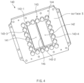
- FIG. 6 is a perspective view of a back plate having no protruding block in the apparatus for manufacturing the pouch of the secondary battery according to Embodiment 2 of the present invention.
- FIG. 7 is a perspective view of a back plate having a protruding block in the apparatus for manufacturing the pouch of the secondary battery according to Embodiment 2 of the present invention.
- FIG. 8 is a side perspective view of the apparatus for manufacturing the pouch of the secondary battery according to Embodiment 2 of the present invention.
- Embodiment 2 of the present invention a method in which a protruding block 243 is installed on a back plate 240 is different from that in Embodiment 1.
- Embodiment 1 The contents that are duplicated with Embodiment 1 will be omitted as much as possible, and Embodiment 2 will be described with a focus on the differences. That is, it is obvious that the contents that are not described in Embodiment 2 may be regarded as the contents of Embodiment 1 if necessary.
- an insertion hole 246 may be formed in the back plate 240, and the protruding block 243 may be inserted into the insertion hole 246.
- the protruding block 243 may be provided in a cylindrical shape, and the insertion hole 246 may have a circular hole shape to correspond to the shape of the protruding block 243.
- a first screw thread 247 may be formed on an inner circumferential surface of the back plate 240 of the insertion hole 246, and a second screw thread 248 having a shape corresponding to the first screw thread 247 may be formed on an outer circumferential surface of the protruding block 243.
- the protruding block 243 may be screw-coupled to the insertion hole 246, and as a degree to which the protruding block 243 is screw-coupled to the insertion hole 246 is adjusted, a protruding height of the protruding block 243 may be adjusted.
- the protruding block 243 may include a first protruding block 243-1 disposed above the through-hole of the back plate 240 and a second protruding block 243-2 disposed below the through-hole of the back plate 240.
- the protruding block 243 may not include a third protruding block 243 disposed on a left side of a through-hole of the back plate 240 and a fourth protruding block 243 disposed on a right side of a through-hole of the back plate 240.
- the protruding block 243 may be provided in plurality.
- the protruding block 243 disposed adjacent above or below an intermediate rib part 245 among the protruding blocks 243 may be formed to have a height higher than that of each of other protruding blocks 243 adjacent to the protruding block 143.
- a pouch area disposed adjacent to the upper and lower sides of the bridge part 113 of the lower die 110 may be pressed more strongly locally to prevent the pouch wrinkles on the region on which the wrinkles occur.
- each of the insertion hole 246 and the screw method is applied as a means for adjusting the height so that the protruding block 243 increases in height.
- the height of the protruding block 243 may be adjusted only by simply turning the protrude block 243.
- each of the plurality of protruding blocks 243 is individually screw-coupled, the height of each of the protruding blocks 243 may be individually adjusted.
- FIG. 8 is a side perspective view illustrating a state in which the protruding block 243 is installed in the apparatus for manufacturing the pouch of the secondary battery according to Embodiment 2 of the present invention. Since the protruding block 243 is a structure installed therein, a position and configuration of the protruding block 143 may be confirmed as a whole through the side perspective view of FIG. 8 .
- the protruding block 243 may pass through the insertion hole 246 of the back plate 240 and then be screw-coupled, and also, the protruding block 243 may protrude in a direction of the stripper 130 with respect to the surface S to locally press the stripper 130.
- FIG. 8 illustrates that the plurality of protruding blocks 243 protrude to different heights as needed. However, for clear distinction, the degree of protrusion of each of the protruding blocks may be shown in the drawings to be exaggerated than in reality.
- the protruding block 243 may be made of a material including steel.
- the protruding block may be made of a material having elasticity.
Landscapes
- Chemical & Material Sciences (AREA)
- Engineering & Computer Science (AREA)
- Chemical Kinetics & Catalysis (AREA)
- Electrochemistry (AREA)
- General Chemical & Material Sciences (AREA)
- Mechanical Engineering (AREA)
- Manufacturing & Machinery (AREA)
- Inorganic Chemistry (AREA)
- Sealing Battery Cases Or Jackets (AREA)
Claims (14)
- Vorrichtung (100) zum Herstellen eines Pouch (10) einer Sekundärbatterie (1), wobei die Vorrichtung (100) umfasst:ein unteres Formwerkzeug (110) aufweisend eine Aufnahmenut (111, 112) zum Formen eines Schalenteils (11, 12) des Pouch (10) auf einer Basisfläche, auf der der Pouch angeordnet ist;einen Stempel (150), der in die Aufnahmenut (111, 112) des unteren Formwerkzeugs (110) eingesetzt ist, um den Schalenteil (11, 12) des Pouch (10) zu formen;einen Abstreifer (130), der über dem unteren Formwerkzeug (110) angeordnet ist, um dem unteren Formwerkzeug (110) zugewandt zu sein, und vorgesehen ist, um einen Umfangsabschnitt (14) des Pouch (10), der um einen Abschnitt angeordnet ist, der durch den Stempel (150) in den Schalenteil (11, 12) des Pouch (10) zu formen ist, von einer Oberseite her zu pressen; undeine Rückplatte (140; 240), die mit dem Abstreifer (130) gekoppelt ist und konfiguriert ist, um den Abstreifer (130) zu stützen,wobei ein vorstehender Block (143; 243), der zu dem Abstreifer (130) hin vorsteht, auf einer Fläche (S) von Flächen der Rückplatte (140; 240) vorgesehen ist, die dem Abstreifer (130) zugewandt ist, wobei die Vorrichtung dadurch gekennzeichnet ist, dassein Durchgangsloch (141, 142), durch das der Stempel (150) hindurchgeht, in der Rückplatte (140; 240) ausgebildet ist.
- Vorrichtung nach Anspruch 1, wobei
der vorstehende Block (143; 243) um das Durchgangsloch (141, 142) herum angeordnet ist. - Vorrichtung nach Anspruch 2, wobei zwei Aufnahmenuten (111, 112), d.h. eine linke Aufnahmenut (111) und eine rechte Aufnahmenut (112), in dem unteren Formwerkzeug (110) ausgebildet sind,der Stempel (150) einen linken Stempel (151), der in die linke Aufnahmenut (111) eingesetzt ist, und einen rechten Stempel (152), der in die rechte Aufnahmenut (112) eingesetzt ist, umfasst,ein linkes Durchgangsloch (141; 241), durch das der linke Stempel (151) hindurchgeht, und ein rechtes Durchgangsloch (142; 242), durch das der rechte Stempel (152) hindurchgeht, in der Rückplatte (140; 240) ausgebildet sind, undder vorstehende Block (143; 243) an einem Umfangsabschnitt sowohl des linken Durchgangslochs (141; 241) als auch des rechten Durchgangslochs (142; 242) angeordnet ist.
- Vorrichtung nach Anspruch 2, wobei in einer Unteransicht der Rückplatte (140; 240) der vorstehende Block (143; 243) umfasst:einen ersten vorstehenden Block (143-1; 243-1), der über dem Durchgangsloch (141, 142) der Rückplatte (140; 240) angeordnet ist; undeinen zweiten vorstehenden Block (143-2; 243-2), der unter dem Durchgangsloch (141, 142) der Rückplatte (140; 240) angeordnet ist.
- Vorrichtung nach Anspruch 2, wobei in einer Unteransicht der Rückplatte (140; 240) der vorstehende Block (143; 243) umfasst:einen dritten vorstehenden Block (143-3), der an einer linken Seite des Durchgangslochs (141, 142) der Rückplatte (140; 240) angeordnet ist; undeinen vierten vorstehenden Block (143-4), der an einer rechten Seite des Durchgangslochs (141, 142) der Rückplatte (140; 240) angeordnet ist.
- Vorrichtung nach Anspruch 2, wobei der vorstehende Block (140; 240) mehrfach vorgesehen ist, und
basierend auf einer Höhe, die von der Fläche (S), die dem Abstreifer (130) zugewandt ist, unter Flächen der Rückplatte (140; 240) gemessen wird, die vorstehenden Blöcke (243) vorstehende Blöcke (243) umfassen, die im Vergleich zu anderen vorstehenden Blöcken (243) unter den mehreren vorstehenden Blöcken (243) unterschiedliche Höhen aufweisen. - Vorrichtung nach Anspruch 3, wobei die Rückplatte einen Zwischenrippenteil (145) umfasst, der zwischen dem linken Durchgangsloch (141; 241) und dem rechten Durchgangsloch (142; 242) angeordnet ist, und
der vorstehende Block (143; 243), der über oder unter dem Zwischenrippenteil (145) unter den vorstehenden Blöcken (143; 243) angeordnet ist, so ausgebildet ist, dass er eine Höhe aufweist, die höher ist als die jedes anderen vorstehenden Blocks (143; 243), der an den vorstehenden Block (143; 243) angrenzt. - Vorrichtung nach Anspruch 3, wobei in den vorstehenden Blöcken (143; 243) der vorstehende Block (143; 243), der an einer Position ausgebildet ist, die zu einer Außenecke (144) des linken Durchgangslochs (141; 241) und des rechten Durchgangslochs (142; 242) benachbart ist, so ausgebildet ist, dass er eine Höhe aufweist, die höher ist als die jedes anderen vorstehenden Blocks (143; 243), der zu ihm benachbart ist.
- Vorrichtung nach Anspruch 1, wobei ein Einsetzloch (246) in der Rückplatte (240) ausgebildet ist, und
der vorstehende Block (143; 243) in das Einsetzloch (246) eingesetzt ist. - Vorrichtung nach Anspruch 9, wobei der vorstehende Block (143, 243) in einer zylindrischen Form vorgesehen ist, und
das Einsetzloch (246) eine kreisförmige Lochform aufweist, die der Form des vorstehenden Blocks (143, 243) entspricht. - Vorrichtung nach Anspruch 10, wobei ein erstes Schraubengewinde (247) auf einer Innenumfangsfläche des Einsetzlochs (246) der Rückplatte (240) ausgebildet ist, und
ein zweites Schraubengewinde (248), das eine Form aufweist, die dem ersten Schraubengewinde (247) entspricht, auf einer Außenumfangsfläche des vorstehenden Blocks (143, 243) ausgebildet ist. - Vorrichtung nach Anspruch 11, wobei der vorstehende Block (143; 243) mit dem Einsetzloch (246) schraubgekoppelt ist, und
wenn ein Grad, zu dem der vorstehende Block (143; 243) mit dem Einsetzloch (246) schraubgekoppelt ist, eingestellt wird, eine vorstehende Höhe des vorstehenden Blocks (143; 243) eingestellt wird. - Vorrichtung nach einem der Ansprüche 1 bis 12, wobei der vorstehende Block (143; 243) aus einem Material hergestellt ist, das Stahl enthält.
- Vorrichtung nach Anspruch 13, wobei der vorstehende Block (143, 243) aus einem Material hergestellt ist, das Elastizität aufweist.
Applications Claiming Priority (3)
| Application Number | Priority Date | Filing Date | Title |
|---|---|---|---|
| KR20200142549 | 2020-10-29 | ||
| KR1020210074475A KR102856331B1 (ko) | 2020-10-29 | 2021-06-08 | 이차전지 파우치 제조장치 |
| PCT/KR2021/014931 WO2022092719A1 (ko) | 2020-10-29 | 2021-10-22 | 이차전지 파우치 제조장치 |
Publications (3)
| Publication Number | Publication Date |
|---|---|
| EP4238739A1 EP4238739A1 (de) | 2023-09-06 |
| EP4238739A4 EP4238739A4 (de) | 2024-03-27 |
| EP4238739B1 true EP4238739B1 (de) | 2025-06-25 |
Family
ID=81384085
Family Applications (1)
| Application Number | Title | Priority Date | Filing Date |
|---|---|---|---|
| EP21886713.3A Active EP4238739B1 (de) | 2020-10-29 | 2021-10-22 | Vorrichtung zur herstellung eines beutels einer sekundärbatterie |
Country Status (6)
| Country | Link |
|---|---|
| US (1) | US12337368B2 (de) |
| EP (1) | EP4238739B1 (de) |
| CN (1) | CN115989612A (de) |
| ES (1) | ES3041543T3 (de) |
| HU (1) | HUE072747T2 (de) |
| WO (1) | WO2022092719A1 (de) |
Family Cites Families (14)
| Publication number | Priority date | Publication date | Assignee | Title |
|---|---|---|---|---|
| US3345896A (en) * | 1964-11-02 | 1967-10-10 | Minnie Punch & Die Company Inc | Punching die set |
| US5706696A (en) * | 1996-09-09 | 1998-01-13 | Wagner; Wendell J. | Modular pressure set and system for stamping press |
| JP3750963B2 (ja) | 1998-02-26 | 2006-03-01 | 日本碍子株式会社 | 昇華性シートの充填方法およびその装置 |
| JP5101906B2 (ja) | 2007-03-06 | 2012-12-19 | 昭和電工パッケージング株式会社 | 電池ケースの成形方法及び成形装置 |
| US8758669B2 (en) * | 2008-06-30 | 2014-06-24 | Ethicon, Inc. | Method and device for forming pre-made pouches |
| WO2015045797A1 (ja) | 2013-09-26 | 2015-04-02 | 株式会社村田製作所 | 絞り加工装置 |
| WO2018127983A1 (ja) * | 2017-01-09 | 2018-07-12 | 黒田精工株式会社 | 積層鉄心の製造装置及び製造方法 |
| KR101904094B1 (ko) * | 2017-07-25 | 2018-10-04 | 주식회사 탑앤씨 | 이차전지용 파우치 필름 성형기 |
| KR20190038094A (ko) | 2017-09-29 | 2019-04-08 | 에스케이이노베이션 주식회사 | 이차 전지의 파우치 성형 장치 |
| JP7052571B2 (ja) | 2018-06-04 | 2022-04-12 | トヨタ自動車株式会社 | 成形装置および成形品の製造方法 |
| KR102131739B1 (ko) | 2018-11-09 | 2020-07-09 | 주식회사 엘지화학 | 파우치 포밍 방법 및 파우치 포밍 장치 |
| EP3806233B1 (de) | 2018-11-09 | 2023-11-22 | LG Energy Solution, Ltd. | Beutelherstellungsvorrichtung |
| KR102145494B1 (ko) | 2018-11-23 | 2020-08-18 | 주식회사 엘지화학 | 파우치 성형장치 및 성형방법, 그를 포함하는 이차전지 제조설비 |
| KR20200117177A (ko) | 2019-04-03 | 2020-10-14 | 현대자동차주식회사 | 이차전지용 파우치 외장재의 제조장치 및 제조방법 |
-
2021
- 2021-10-22 US US18/025,084 patent/US12337368B2/en active Active
- 2021-10-22 HU HUE21886713A patent/HUE072747T2/hu unknown
- 2021-10-22 WO PCT/KR2021/014931 patent/WO2022092719A1/ko not_active Ceased
- 2021-10-22 CN CN202180052849.1A patent/CN115989612A/zh active Pending
- 2021-10-22 ES ES21886713T patent/ES3041543T3/es active Active
- 2021-10-22 EP EP21886713.3A patent/EP4238739B1/de active Active
Also Published As
| Publication number | Publication date |
|---|---|
| ES3041543T3 (en) | 2025-11-12 |
| HUE072747T2 (hu) | 2025-12-28 |
| US20230321709A1 (en) | 2023-10-12 |
| US12337368B2 (en) | 2025-06-24 |
| EP4238739A1 (de) | 2023-09-06 |
| WO2022092719A1 (ko) | 2022-05-05 |
| CN115989612A (zh) | 2023-04-18 |
| EP4238739A4 (de) | 2024-03-27 |
Similar Documents
| Publication | Publication Date | Title |
|---|---|---|
| EP4234196B1 (de) | Vorrichtung zur herstellung eines sekundärbatteriebeutels | |
| KR101192619B1 (ko) | 전지케이스 | |
| KR101467859B1 (ko) | 이차전지용 전지케이스 | |
| CN114303278B (zh) | 袋型电池壳体、制造袋型电池壳体的设备及袋型二次电池 | |
| US20190334131A1 (en) | Pouch Cell and Method of Forming Same | |
| KR20160115167A (ko) | 측면 밀봉 잉여부가 절곡된 전지셀의 제조방법 | |
| EP4238739B1 (de) | Vorrichtung zur herstellung eines beutels einer sekundärbatterie | |
| KR20190054419A (ko) | 이차전지 | |
| KR102561762B1 (ko) | 이차 전지 | |
| KR20220057406A (ko) | 이차전지 파우치 제조장치 | |
| EP3159959B1 (de) | Batteriezelle mit batteriegehäuse mit geformtem projektionsteil darauf entsprechend einer stufenartig strukturierten elektrodenanordnung | |
| KR101739300B1 (ko) | 이차전지 | |
| KR20180093598A (ko) | 전지셀의 실링 잉여부 가공 장치 | |
| EP4596204A1 (de) | Formvorrichtung und formverfahren sowie damit geformtes beutelartiges batteriegehäuse | |
| KR20180034903A (ko) | 수납부 및 전극 리드용 그루브를 포함하는 전지케이스를 구비한 전지셀 | |
| EP4234195B1 (de) | Vorrichtung zur herstellung eines sekundärbatteriebeutels | |
| EP4674596A1 (de) | Formvorrichtung | |
| US12434413B2 (en) | Pouch molding apparatus and method | |
| EP4603253A1 (de) | Formvorrichtung und formverfahren sowie damit geformtes beutelartiges batteriegehäuse | |
| US20230369687A1 (en) | Apparatus For Manufacturing Pouch Of Secondary Battery And Pouch Of Secondary Battery Manufactured Thereby | |
| US6826034B2 (en) | Vibration-resistant electrochemical cell, and method for the production thereof | |
| US20260038918A1 (en) | Apparatus for Molding Secondary Battery Pouch and Secondary Battery Pouch Manufactured Thereby | |
| KR20230070964A (ko) | 포밍 장치 | |
| WO2025074892A1 (ja) | 電池装置 |
Legal Events
| Date | Code | Title | Description |
|---|---|---|---|
| STAA | Information on the status of an ep patent application or granted ep patent |
Free format text: STATUS: THE INTERNATIONAL PUBLICATION HAS BEEN MADE |
|
| PUAI | Public reference made under article 153(3) epc to a published international application that has entered the european phase |
Free format text: ORIGINAL CODE: 0009012 |
|
| STAA | Information on the status of an ep patent application or granted ep patent |
Free format text: STATUS: REQUEST FOR EXAMINATION WAS MADE |
|
| 17P | Request for examination filed |
Effective date: 20230220 |
|
| AK | Designated contracting states |
Kind code of ref document: A1 Designated state(s): AL AT BE BG CH CY CZ DE DK EE ES FI FR GB GR HR HU IE IS IT LI LT LU LV MC MK MT NL NO PL PT RO RS SE SI SK SM TR |
|
| DAV | Request for validation of the european patent (deleted) | ||
| DAX | Request for extension of the european patent (deleted) | ||
| A4 | Supplementary search report drawn up and despatched |
Effective date: 20240222 |
|
| RIC1 | Information provided on ipc code assigned before grant |
Ipc: B29L 31/34 20060101ALN20240216BHEP Ipc: B29C 51/14 20060101ALN20240216BHEP Ipc: H01M 50/10 20210101ALI20240216BHEP Ipc: H01M 10/04 20060101ALI20240216BHEP Ipc: B29C 51/30 20060101ALI20240216BHEP Ipc: B29C 51/08 20060101ALI20240216BHEP Ipc: B29C 51/26 20060101AFI20240216BHEP |
|
| GRAP | Despatch of communication of intention to grant a patent |
Free format text: ORIGINAL CODE: EPIDOSNIGR1 |
|
| STAA | Information on the status of an ep patent application or granted ep patent |
Free format text: STATUS: GRANT OF PATENT IS INTENDED |
|
| RIC1 | Information provided on ipc code assigned before grant |
Ipc: B29L 31/34 20060101ALN20250402BHEP Ipc: B29C 51/14 20060101ALN20250402BHEP Ipc: H01M 50/10 20210101ALI20250402BHEP Ipc: H01M 10/04 20060101ALI20250402BHEP Ipc: B29C 51/30 20060101ALI20250402BHEP Ipc: B29C 51/08 20060101ALI20250402BHEP Ipc: B29C 51/26 20060101AFI20250402BHEP |
|
| INTG | Intention to grant announced |
Effective date: 20250414 |
|
| GRAS | Grant fee paid |
Free format text: ORIGINAL CODE: EPIDOSNIGR3 |
|
| GRAA | (expected) grant |
Free format text: ORIGINAL CODE: 0009210 |
|
| STAA | Information on the status of an ep patent application or granted ep patent |
Free format text: STATUS: THE PATENT HAS BEEN GRANTED |
|
| AK | Designated contracting states |
Kind code of ref document: B1 Designated state(s): AL AT BE BG CH CY CZ DE DK EE ES FI FR GB GR HR HU IE IS IT LI LT LU LV MC MK MT NL NO PL PT RO RS SE SI SK SM TR |
|
| P01 | Opt-out of the competence of the unified patent court (upc) registered |
Free format text: CASE NUMBER: APP_24173/2025 Effective date: 20250521 |
|
| REG | Reference to a national code |
Ref country code: GB Ref legal event code: FG4D |
|
| REG | Reference to a national code |
Ref country code: CH Ref legal event code: EP |
|
| REG | Reference to a national code |
Ref country code: CH Ref legal event code: EP |
|
| REG | Reference to a national code |
Ref country code: IE Ref legal event code: FG4D |
|
| REG | Reference to a national code |
Ref country code: DE Ref legal event code: R096 Ref document number: 602021033075 Country of ref document: DE |
|
| PG25 | Lapsed in a contracting state [announced via postgrant information from national office to epo] |
Ref country code: FI Free format text: LAPSE BECAUSE OF FAILURE TO SUBMIT A TRANSLATION OF THE DESCRIPTION OR TO PAY THE FEE WITHIN THE PRESCRIBED TIME-LIMIT Effective date: 20250625 |
|
| REG | Reference to a national code |
Ref country code: LT Ref legal event code: MG9D |
|
| PG25 | Lapsed in a contracting state [announced via postgrant information from national office to epo] |
Ref country code: NO Free format text: LAPSE BECAUSE OF FAILURE TO SUBMIT A TRANSLATION OF THE DESCRIPTION OR TO PAY THE FEE WITHIN THE PRESCRIBED TIME-LIMIT Effective date: 20250925 Ref country code: GR Free format text: LAPSE BECAUSE OF FAILURE TO SUBMIT A TRANSLATION OF THE DESCRIPTION OR TO PAY THE FEE WITHIN THE PRESCRIBED TIME-LIMIT Effective date: 20250926 |
|
| PG25 | Lapsed in a contracting state [announced via postgrant information from national office to epo] |
Ref country code: BG Free format text: LAPSE BECAUSE OF FAILURE TO SUBMIT A TRANSLATION OF THE DESCRIPTION OR TO PAY THE FEE WITHIN THE PRESCRIBED TIME-LIMIT Effective date: 20250625 |
|
| PGFP | Annual fee paid to national office [announced via postgrant information from national office to epo] |
Ref country code: BE Payment date: 20250922 Year of fee payment: 5 Ref country code: GB Payment date: 20250922 Year of fee payment: 5 |
|
| PG25 | Lapsed in a contracting state [announced via postgrant information from national office to epo] |
Ref country code: HR Free format text: LAPSE BECAUSE OF FAILURE TO SUBMIT A TRANSLATION OF THE DESCRIPTION OR TO PAY THE FEE WITHIN THE PRESCRIBED TIME-LIMIT Effective date: 20250625 |
|
| PGFP | Annual fee paid to national office [announced via postgrant information from national office to epo] |
Ref country code: FR Payment date: 20250925 Year of fee payment: 5 |
|
| PG25 | Lapsed in a contracting state [announced via postgrant information from national office to epo] |
Ref country code: RS Free format text: LAPSE BECAUSE OF FAILURE TO SUBMIT A TRANSLATION OF THE DESCRIPTION OR TO PAY THE FEE WITHIN THE PRESCRIBED TIME-LIMIT Effective date: 20250925 |
|
| PG25 | Lapsed in a contracting state [announced via postgrant information from national office to epo] |
Ref country code: LV Free format text: LAPSE BECAUSE OF FAILURE TO SUBMIT A TRANSLATION OF THE DESCRIPTION OR TO PAY THE FEE WITHIN THE PRESCRIBED TIME-LIMIT Effective date: 20250625 |
|
| REG | Reference to a national code |
Ref country code: NL Ref legal event code: MP Effective date: 20250625 |
|
| REG | Reference to a national code |
Ref country code: ES Ref legal event code: FG2A Ref document number: 3041543 Country of ref document: ES Kind code of ref document: T3 Effective date: 20251112 |
|
| PGFP | Annual fee paid to national office [announced via postgrant information from national office to epo] |
Ref country code: HU Payment date: 20251029 Year of fee payment: 5 |
|
| PG25 | Lapsed in a contracting state [announced via postgrant information from national office to epo] |
Ref country code: NL Free format text: LAPSE BECAUSE OF FAILURE TO SUBMIT A TRANSLATION OF THE DESCRIPTION OR TO PAY THE FEE WITHIN THE PRESCRIBED TIME-LIMIT Effective date: 20250625 |
|
| PG25 | Lapsed in a contracting state [announced via postgrant information from national office to epo] |
Ref country code: PT Free format text: LAPSE BECAUSE OF FAILURE TO SUBMIT A TRANSLATION OF THE DESCRIPTION OR TO PAY THE FEE WITHIN THE PRESCRIBED TIME-LIMIT Effective date: 20251027 |
|
| REG | Reference to a national code |
Ref country code: AT Ref legal event code: MK05 Ref document number: 1806042 Country of ref document: AT Kind code of ref document: T Effective date: 20250625 |
|
| REG | Reference to a national code |
Ref country code: HU Ref legal event code: AG4A Ref document number: E072747 Country of ref document: HU |
|
| PG25 | Lapsed in a contracting state [announced via postgrant information from national office to epo] |
Ref country code: IS Free format text: LAPSE BECAUSE OF FAILURE TO SUBMIT A TRANSLATION OF THE DESCRIPTION OR TO PAY THE FEE WITHIN THE PRESCRIBED TIME-LIMIT Effective date: 20251025 |
|
| PGFP | Annual fee paid to national office [announced via postgrant information from national office to epo] |
Ref country code: DE Payment date: 20250922 Year of fee payment: 5 |
|
| PG25 | Lapsed in a contracting state [announced via postgrant information from national office to epo] |
Ref country code: AT Free format text: LAPSE BECAUSE OF FAILURE TO SUBMIT A TRANSLATION OF THE DESCRIPTION OR TO PAY THE FEE WITHIN THE PRESCRIBED TIME-LIMIT Effective date: 20250625 Ref country code: SM Free format text: LAPSE BECAUSE OF FAILURE TO SUBMIT A TRANSLATION OF THE DESCRIPTION OR TO PAY THE FEE WITHIN THE PRESCRIBED TIME-LIMIT Effective date: 20250625 |
|
| PG25 | Lapsed in a contracting state [announced via postgrant information from national office to epo] |
Ref country code: CZ Free format text: LAPSE BECAUSE OF FAILURE TO SUBMIT A TRANSLATION OF THE DESCRIPTION OR TO PAY THE FEE WITHIN THE PRESCRIBED TIME-LIMIT Effective date: 20250625 |
|
| PG25 | Lapsed in a contracting state [announced via postgrant information from national office to epo] |
Ref country code: PL Free format text: LAPSE BECAUSE OF FAILURE TO SUBMIT A TRANSLATION OF THE DESCRIPTION OR TO PAY THE FEE WITHIN THE PRESCRIBED TIME-LIMIT Effective date: 20250625 |
|
| PG25 | Lapsed in a contracting state [announced via postgrant information from national office to epo] |
Ref country code: EE Free format text: LAPSE BECAUSE OF FAILURE TO SUBMIT A TRANSLATION OF THE DESCRIPTION OR TO PAY THE FEE WITHIN THE PRESCRIBED TIME-LIMIT Effective date: 20250625 |
|
| PG25 | Lapsed in a contracting state [announced via postgrant information from national office to epo] |
Ref country code: SK Free format text: LAPSE BECAUSE OF FAILURE TO SUBMIT A TRANSLATION OF THE DESCRIPTION OR TO PAY THE FEE WITHIN THE PRESCRIBED TIME-LIMIT Effective date: 20250625 |
|
| PGFP | Annual fee paid to national office [announced via postgrant information from national office to epo] |
Ref country code: ES Payment date: 20251117 Year of fee payment: 5 |
|
| PG25 | Lapsed in a contracting state [announced via postgrant information from national office to epo] |
Ref country code: RO Free format text: LAPSE BECAUSE OF FAILURE TO SUBMIT A TRANSLATION OF THE DESCRIPTION OR TO PAY THE FEE WITHIN THE PRESCRIBED TIME-LIMIT Effective date: 20250625 |
|
| PG25 | Lapsed in a contracting state [announced via postgrant information from national office to epo] |
Ref country code: DK Free format text: LAPSE BECAUSE OF FAILURE TO SUBMIT A TRANSLATION OF THE DESCRIPTION OR TO PAY THE FEE WITHIN THE PRESCRIBED TIME-LIMIT Effective date: 20250625 |
|
| PG25 | Lapsed in a contracting state [announced via postgrant information from national office to epo] |
Ref country code: IT Free format text: LAPSE BECAUSE OF FAILURE TO SUBMIT A TRANSLATION OF THE DESCRIPTION OR TO PAY THE FEE WITHIN THE PRESCRIBED TIME-LIMIT Effective date: 20250625 |