EP4238710B1 - Robotersystem für aluminiumofenoperationen - Google Patents
Robotersystem für aluminiumofenoperationen Download PDFInfo
- Publication number
- EP4238710B1 EP4238710B1 EP22213226.8A EP22213226A EP4238710B1 EP 4238710 B1 EP4238710 B1 EP 4238710B1 EP 22213226 A EP22213226 A EP 22213226A EP 4238710 B1 EP4238710 B1 EP 4238710B1
- Authority
- EP
- European Patent Office
- Prior art keywords
- robotic system
- assembly
- tool
- driving
- arm
- Prior art date
- Legal status (The legal status is an assumption and is not a legal conclusion. Google has not performed a legal analysis and makes no representation as to the accuracy of the status listed.)
- Active
Links
Images


Classifications
-
- B—PERFORMING OPERATIONS; TRANSPORTING
- B25—HAND TOOLS; PORTABLE POWER-DRIVEN TOOLS; MANIPULATORS
- B25J—MANIPULATORS; CHAMBERS PROVIDED WITH MANIPULATION DEVICES
- B25J9/00—Programme-controlled manipulators
- B25J9/02—Programme-controlled manipulators characterised by movement of the arms, e.g. cartesian coordinate type
- B25J9/04—Programme-controlled manipulators characterised by movement of the arms, e.g. cartesian coordinate type by rotating at least one arm, excluding the head movement itself, e.g. cylindrical coordinate type or polar coordinate type
- B25J9/041—Cylindrical coordinate type
- B25J9/042—Cylindrical coordinate type comprising an articulated arm
-
- B—PERFORMING OPERATIONS; TRANSPORTING
- B25—HAND TOOLS; PORTABLE POWER-DRIVEN TOOLS; MANIPULATORS
- B25J—MANIPULATORS; CHAMBERS PROVIDED WITH MANIPULATION DEVICES
- B25J5/00—Manipulators mounted on wheels or on carriages
-
- B—PERFORMING OPERATIONS; TRANSPORTING
- B25—HAND TOOLS; PORTABLE POWER-DRIVEN TOOLS; MANIPULATORS
- B25J—MANIPULATORS; CHAMBERS PROVIDED WITH MANIPULATION DEVICES
- B25J9/00—Programme-controlled manipulators
- B25J9/06—Programme-controlled manipulators characterised by multi-articulated arms
Definitions
- the subject matter disclosed generally relates to systems for operating furnaces. More particularly, the subject matter disclosed relates to systems for performing furnace tending processes.
- Furnace tending is one of the least automated activities in cast houses.
- the general practice for furnaces ranging from 10-20 metric tons up to 120 metric tons is to have charging done using vehicles or dedicated charging machines, and other activities such as mixing using electromagnetic stirrers or large vehicles fitted with long and cumbersome metallic attachments.
- Skimming and cleaning are other activities carried out using wheel-based vehicles or dedicated rail mounted equipment.
- AGVs Automated Guided Vehicles
- AMRs 130, Fig. 2 Autonomous Mobile Robots
- Robotization helps reduce production costs by improving productivity and consistency of operations as well as maintenance costs for furnace tending equipment and furnace refractories.
- Another aspect resides in workspace management.
- the interaction between vehicles and pedestrians is also one important risk factor in cast houses. Efforts are made to prevent pedestrians and vehicles from passing each other but avoiding all risks of interactions remains impossible.
- diesel powered vehicles pose a health risk due to the possible build-up of carbon monoxide and exhaust gases if the area is not properly ventilated. Efforts are being made to electrify these vehicles, but they are still in the early phases of implementation.
- Specialized machines such as those used for charging and skimming, are very efficient by design to their specific functions. Most of the time, however, such use of such specialized machines is limited where furnaces are features a specific alignment, so that rails can be used to displace the specialized machines. Moreover, furnaces, to be serviceable with the same specialized equipment, must be identical or at least very similar. Accordingly, even with the use of specialized machines, more specialized operations such as furnace cleaning still require human intervention with more specialized tooling (usually involving the need for a vehicle).
- furnace operations are in the critical path for delivering metal to the casting equipment
- cast house managers wish to avoid anything that can disrupt the flow of metal, including delays in furnace operations.
- operators perform operations that are in the critical path, this adds pressure to all cast house operations.
- Robotization of furnace tending challenges
- Shape and size of the furnace (including variation in shape)
- any typical reverb furnace is a wide and shallow aperture.
- Most robots available on the market are designed to operate in a somewhat spherical volume, and the arms, because of their shape, occupy a large portion of this volume when simulating operations.
- the area of the metal bath inside the furnace also poses a challenge, as it requires sweeping movements, inside the furnace, which far exceed the capacity of existing robots.
- the shape of the inside of the furnace is not identical from one furnace to another - and even over the life span of a given furnace, the shape of the refractory may change due to wear, thermal deformation of the shell, or residue buildup. This poses a challenge for the path of the cleaning tool the robot must be able to exert.
- Robots available nowadays are mainly designed for high velocity, low load applications.
- the limitations also include moments and inertia to be considered, which further reduces the available payload a robot may undergo.
- the highest loads available of such robots are in the order of 2300 kg. Although this seems a heavy lift, it is small compared to the weight and moment of inertia of a tool that must be able to reach the back wall of a 100 MT (Metric Ton) holding furnace.
- US patent no. 10,751,888 B2 pertaining to a MANIPULATOR APPARATUS FOR OPERATING ON ARTICLES, developed by ADVANCED INTELLIGENT SYSTEMS INC.
- the document describes a manipulator apparatus for operating on articles.
- the apparatus includes a column having a mounting portion for securing the manipulator to a base and an extensible portion that is moveable over an extension range with respect to the mounting portion in response to an actuation force provided by a column actuator.
- the apparatus also includes an arm mounted to the extensible portion of the column at an arm joint and rotatable about the arm joint in response to an actuation torque provided by an arm rotation actuator.
- the apparatus further includes an end effector operably configured to perform an operation on the articles, the end effector being mounted at an end effector joint disposed at an end of the arm distal to the arm joint, the end effector being rotatable about the end effector joint in response to an actuation torque provided by an end effector rotation actuator.
- the rotation of the end effector occurs within an end effector movement plane and the rotation of the arm occurs within an arm movement plane, the respective movement planes being substantially parallel to each other, and the extensible portion of the column is moveable in a direction normal to the respective movement planes and the extensible portion of the column causes the arm joint to be disposed to permit clearance for a full 360° rotation of the arm over at least a portion of the extension range of the extensible portion of the column to provide an operating range within which the end effector is able to move for operating on the articles.
- Patent publication application no. WO 2021/086745 A1 pertaining to a WAFER HANDLING ROBOT WITH GRAVITATIONAL FIELD SENSOR, developed by LAM RES CORP .
- the document describes techniques and systems for automatically determining and correcting the levelness of a wafer handling robot end effector.
- the systems may use a tilt sensor or a gravitational field sensor which may be calibrated to the wafer handling robot.
- the output from the tilt sensor may be used to determine or estimate the tilt of an end effector of the wafer handling robot and to perform correctional positioning to reduce or eliminate the tilt, to automatically teach certain positions that have reduced tilt, to perform health checks on the robot, provide feedback to a user, etc.
- US patent no. 5,634,377 A pertains to an ARTICULATED ROBOT, developed by SONY CORP .
- the document describes a robot that has a base shaft portion disposed on a base, a first arm attached in a rotatable state to the base shaft portion, and a second arm attached in a rotatable state to the first arm.
- Balance setting is performed so as to position the center of gravity of the second arm above the rotation shaft of the second arm.
- a support arm of the housing is supported in a rotatable and slidable state along the length direction of the first arm by a support member fixed to the base shaft portion. In adjusting the tension of the steel belt the housing is displaced by a setting bolt to change the gap between the rotation shaft of the second arm and the output shaft of the harmonic reduction gear.
- US patent no. 4,568,238 A pertains to a HORIZONTAL MULTI-LINK TYPE ROBOT, developed by TOYODA MACHINE WORKS .
- the document describes a horizontal multi-link type robot has servomotors for rotating first and second arms, respectively. These servomotors are mounted to a first arm support shaft so as to be symmetrical with respect to this shaft.
- the first arm is mounted to the first arm support shaft so as to be rotatable in a horizontal plane.
- the second arm is mounted to a second arm support shaft, which extends parallel to the first arm support shaft and is rotatably held to the first arm.
- a tool holding shaft extends parallel to the second arm support shaft and is rotatably held to the second arm.
- the techniques described herein relate to a stationary robotic system adapted for performing a furnace tending process, the stationary robotic system including: a platform movable between stations; an arm assembly rotatably mounted to the platform about a first axis, the arm assembly including a first arm rotatably mounted to the platform, and a second arm rotatably mounted to the first arm about a second axis distant to the first axis; and a tool driving assembly rotatably mounted to the second arm about a third axis distant to the second axis, the tool driving assembly being adapted to drive extension and operating angle of a tool relative to horizontal, wherein the robotic system provides a spatial range of base points for the tool with the stationary robotic system remaining stationary.
- the techniques described herein relate to a robotic system including: a self-standing platform movable between stations; an articulated arm assembly rotatably mounted to the platform around a first axis, the articulated arm assembly including at least one joint flexible through a second axis, and a third axis farther to the first axis than the joint, with the first axis and the second axis being parallel to each other; a tool driving assembly rotatably mounted to the articulated arm about the third axis; powering assembly fixedly mounted to the articulated arm assembly, whereby the powering assembly is rotatable with the articulated arm assembly about the first axis; driving assemblies for driving a first movement of the articulated arm assembly relative to the first axis, driving a second movement of the articulated arm assembly relative to the second axis, driving a third movement of the tool driving assembly relative to the third axis and driving the tool driving assembly; wherein driving assemblies are connected to the powering assembly.
- the techniques described herein relate to a robotic system, wherein the powering assembly includes a hydraulic powering pump.
- the techniques described herein relate to a robotic system, wherein the articulated arm assembly is a SCARA arm assembly including arms rotabably mounted to each other via a slew bearing.
- the techniques described herein relate to a robotic system, wherein the SCARA arm assembly includes a passageway extending through the arms and the slew bearing.
- the techniques described herein relate to a robotic system, further including a power artery extending through the passageway, the power artery including a means for transmitting hydraulic power, a command cable and an electric power cable, wherein the power artery is connected to at least one of the driving assemblies.
- the techniques described herein relate to a robotic system, wherein the tool driving assembly is rotatably mounted to the articulated arm assembly, the tool driving assembly driving a tool according to at least two degrees of freedom.
- the techniques described herein relate to a robotic system, wherein the self-standing platform includes extendable legs, monitoring components designed to monitor stability of the platform, and driving components connected to the legs to controllably adapt extension of the legs to maintain stability of the platform.
- the techniques described herein relate to a robotic system, wherein at least one of the driving assemblies includes a control valve, fed with hydraulic power, that is adapted to receive a target position command, a hydraulic actuator connected to the control valve, and a sensor designed to transmit a position signal changing with operation of the actuator to the control valve, wherein the control valve is adapted compare the target position command with the position signal, and to transmit hydraulic power to the hydraulic actuator accordingly.
- the techniques described herein relate to a robotic system comprising a hydraulic powering pump consists in a variable displacement pump, with the robotic system further comprising a kidney loop, and a fix displacement pump operating in relation with the kidney loop.
- the techniques described herein relate to a robotic system, wherein the powering assembly includes a fan adapted to cool down fluid circulating in the kidney loop.
- the techniques described herein relate to a robotic system, wherein the powering assembly includes battery cells.
- the techniques described herein relate to a robotic system, wherein the powering assembly is mounted to the articulated arm assembly distant to the third axis, whereby the powering assembly at least partially balancing dead load generated by the tool driving assembly.
- the techniques described herein relate to a robotic system, wherein at least one of: the articulated arm assembly is adapted to flex over at least 270 degrees; and the articulated arm assembly is adapted to rotate relative to the platform over at least 270 degrees.
- the techniques described herein relate to a robotic system, further including a controllable one-flow valve connected to a hydraulic actuator, wherein the controllable one-flow valve operates as a hydraulic brake for one of the driving assemblies.
- the techniques described herein relate to a robotic system, further including a controller assembly and an imaging subsystem including an image capture component, wherein the robotic system includes an automation program adapted for autonomously operating based on at least an image captured by the imaging subsystem and the automation program.
- the techniques described herein relate to a robotic system including: a platform movable between stations; an arm assembly rotatably mounted to the platform around a first axis, a tool driving assembly rotatably mounted to the articulated arm, with the tool driving assembly being rotatable about a tool axis distant from the first axis; a powering assembly fixedly mounted to the articulated arm, whereby the powering assembly is rotatable with the articulated arm about the first axis; at least one driving assembly including a control valve, an actuator and a sensor, the driving assembly being for driving one of a) a movement of the arm assembly relative to the platform; and b) a movement of the driving tool assembly relative to the arm assembly; powering artery including hydraulic tubing, electric cables and a command cable, the powering artery connecting the powering components to the driving assembly, with the command cable being adapted for transmitting a command signal to the control valve about a target position, the hydraulic tubing feeding the control valve with hydraulic power, and the electric cables electrical
- the techniques described herein relate to a robotic system including: a platform movable between stations; an arm assembly rotatably mounted to the platform through a first slew bearing, the arm assembly including a first arm rotatably mounted to the platform, and a second arm rotatably mounted to the first arm through a second slew bearing distant to the first slew bearing; and a tool driving assembly rotatably mounted to the first arm through a third slew bearing distant to the second slew bearing, the tool driving assembly being adapted to drive extension and operating angle of a tool relative to horizontal, wherein the robotic system provides a spatial range of base points for the tool with the stationary robotic system remaining stationary.
- references to items in the singular should be understood to include items in the plural, and vice versa, unless explicitly stated otherwise or clear from the text.
- Grammatical conjunctions are intended to express any and all disjunctive and conjunctive combinations of conjoined clauses, sentences, words, and the like, unless otherwise stated or clear from the context.
- the term “or” should generally be understood to mean “and/or” and so forth.
- top up, “upper”, “bottom”, “lower”, “down”, “vertical”, “horizontal”, “interior” and “exterior” and the like are intended to be construed in their normal meaning in relation with normal installation of the product, with indication of normal orientation of the robotic system being provided on Fig. 1 .
- the term "coupled” means the joining of two members directly or indirectly to one another. Such joining may be stationary in nature or movable in nature and/or such joining may allow for the flow of fluids, electricity, electrical signals, or other types of signals or communication between two members. Such joining may be achieved with the two members, or the two members and any additional intermediate members being integrally formed as a single unitary body with one another or with the two members or the two members and any additional intermediate members being attached to one another. Such joining may be permanent in nature or alternatively may be removable or releasable in nature.
- a robotic system and components of a robotic system More precisely, there is disclosed a stationary robotic system for furnace tending operations, and more particularly for aluminum furnace tending operations.
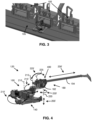
- the stationary robotic system must be operational, with few to no modifications both a) in cast houses comprising a railing system (see ex. Fig. 3 ), wherein the railing system is adapted to move the robotic system between stations (in front of a selected furnace and away from the furnaces); and b) in cast houses where Autonomous Mobile Robots (AMRs) (see ex. Fig. 2 ) or Automated Guided Vehicles (AGVs) are adapted to move the robotic system (see ex. Fig. 1 ) between stations (facing the door of a selected furnace and away from the furnaces).
- AMRs Autonomous Mobile Robots
- AGVs Automated Guided Vehicles
- the robotic system is movable between stations, aka facing one furnace to facing another furnace.
- the robotic system is adapted with an autonomous power supply, preventing the robotic system to be stuck in a permanent location or the necessity of using of a power cable to power the robotic system, what would clutter up the workplace.
- the autonomous power source is the preferred realization of the robotic system, regardless of the solution used to move the robotic system between stations.
- the robotic system be powered through a power cable connecting the robotic system to a power source, e.g., the grid, when performing operations, connected the robotic system whenever the robotic system is installed at a station, or wherein its battery cells are low.
- a power source e.g., the grid
- the robotic system be able to perform different specialized tasks using with the same tool.
- Such specialized tasks comprise a skimming task, a cleaning task, a mixing task, and addition of material (other metal and additives for alloy formation and post-consumption material) in the furnace by pushing material off a platform temporarily placed between the robotic system in the furnace.
- a robotic system e.g., robotic system 120 of Fig. 1
- a transport vehicle e.g., AMR 130
- Other embodiments e.g., robotic system of Fig. 3
- a railing system 105 having a path extending in front of furnaces 100.
- the robotic system 120 consists of a, e.g., self-elevating and self-leveling platform 140 on which is rotatably mounted a Selectively Compliant Articulated Robot Arm, aka SCARA, arm assembly 160, and more precisely an articulated SCARA arm assembly 160, at the distal extremity of which is rotatably mounted a tool driving assembly 180 adapted to drive a tool 194.
- a Selectively Compliant Articulated Robot Arm aka SCARA, arm assembly 160
- SCARA Selectively Compliant Articulated Robot Arm
- tool driving assembly 180 adapted to drive a tool 194.
- the arm assembly of the robotic system 120 is an articulated SCARA arm assembly.
- the arm assembly may comprise a single arm, or a plurality of , aka two or more, articulated arms having joints connecting them, the arms being thus flexible relative to each other. Selection of one option may depend, e.g., on the reach desired for the arm assembly.
- axis(es) of the joint(s) and of the rotatable mounting of the arm assembly to the platform are parallel to each other, and preferably vertical. Therefore, the structure of the robotic system 120 may support the dead load of the arm assembly and components mounted thereto, e.g., tool driving assembly, without the dead load exerting a load toward relative movements of components the gravitation may compel toward.
- the combination of the SCARA arm assembly 160 and the tool driving assembly 180 features together five degrees of freedom, comprising the following degrees of freedom:
- the robotic system 120 is further adapted to be customizable regarding its operating height.
- the robotic system 120 is adapted to set the elevation of the platform following displacement axis to stand on the ground, freeing thereby the robotic system 120 from, e.g., the AMR 130.
- the robotic system 120 is adapted to raise in a stable position among a plurality of available stable positions, aka heights of the platform 140, which allows the robotic system 120 to adjust its height according to the height of the door sill of the furnace 100 to tend.
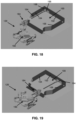
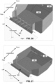
- the robotic system 120 comprises a platform 140 adapted to elevate and level itself when powered.
- the platform 140 comprises a pair of scissor elevating legs 142 driven by hydraulic actuators 144. Operation of the hydraulic actuators 144 allows to drive the platform 140 between a) an operating position wherein the platform 140 stands on the ground with the scissor legs 142 extended, with the operating position allowing to tend the furnace 100; and b) an transport position (e.g., Fig.
- the platform 140 comprises scissor legs 142 with hydraulic components, e.g., two (2) to four (4) hydraulic actuators 150, adapted to adjust the scissor legs 142 and level the platform 140.
- hydraulic actuators 150 are operating to level the deck 152.
- hydraulic pressure in the hydraulic actuators 150 is monitored during furnace tending operations to ensure stability of the robotic system 120 throughout the operation. Such monitoring allows the controller assembly 112, Fig. 22 , to limit the operating speed and position the tool 194 can adopt at any time during the furnace tending operation.
- controllable one-way valves e.g., controllable one-way valve 358, Fig. 14 , are mounted to the fluid conduits.
- the controllable one-way valves allow to lock the elevation of the platform 140 during a furnace tending process.
- hydraulic pressure monitoring is performed over the hydraulic actuators 150 during tending process, with the robotic system 120 therethrough monitoring stability of the robotic system 120 in real time and thereby be able to adjust extension of the hydraulic actuators 150 if the level of the robotic system 120 is affected in any way during the tending operation.
- the robotic system 120 is both adapted to elevate itself to an operating position, to level itself, but also to monitor the level and correct the level during tending operation.
- the platform 140 comprises an underbelly 146 facing downward adapted to butt off against the AMR for displacements, and a deck 152 opposed to the underbelly 146, facing upward.
- a first rotation means preferably a first slew bearing 154, through which is rotatably mounted the SCARA first arm 170 to the platform 140, is designed to allow the SCARA first arm 170 to rotate around the first axis 210.
- the slew bearing 154 is adapted to support weight, moments, and generally all static efforts the SCARA arm assembly 160 may transmit to the platform 140.
- slew bearings such as slew bearing 154
- SCARA arm assembly 160 of the robotic system 120 alternative components may also be used in alternative embodiments without automatically departing from the scope of the present description.
- slew bearings are part of preferred embodiments since advantageous. They provide additional advantages over most alternatives, comprising great resistance to static forces and moments, free rotation of components relative to each other, and a passageway the present robotic system 120 takes advantage of as will be more understandable considering more detailed description hereinafter.
- the SCARA arm assembly 160 comprises a SCARA first arm 170 mounted to the first slew bearing 154 which defines the rotation axis 210 of the SCARA first arm 170 relative to the deck 152.
- the SCARA first arm 170 has, mounted along about the first slew bearing 154, e.g., a control cabinet 164, a battery cabinet 166 housing preferably battery cells, and power cabinet 168 housing a control panel and hydraulic pump assembly .
- the SCARA first arm 170 has a second slew bearing 172 mounted thereto distant to the first slew bearing 154 with the SCARA second arm 176 rotatably mounted thereto.
- the second slew bearing 172 defines the rotation axis 215.
- a SCARA second arm 176 is rotatably mounted to the second slew bearing 172 allowing rotation of the SCARA second arm 176 relative to the SCARA first arm 170 around the rotation axis 215.
- the robotic system 120 comprises a raisable platform 140, and an articulated SCARA arm assembly 160 rotatably mounted thereto, wherein the SCARA arm assembly 160 comprises at least two SCARA arms 170, 176 rotatably mounted to each other, further wherein cabinets 164, 166, 168 are fixedly mounted to the 160, thereby being rotatable with the SCARA arm assembly 160 relative to the platform 140.
- the SCARA second arm 176 has a third slew bearing 174 mounted thereto distant to the second slew bearing 172 with a tool assembly reference point 235 defined thereto.
- the third slew bearing 174 defines the rotation axis 220.
- a tool driving assembly 180 is rotatably mounted to the third slew bearing 174 allowing rotation of the tool driving assembly 180 relative to the SCARA arm assembly 160, and more precisely the SCARA second arm 176, around the axis 220.
- the rotations axis 210, 215, 220 are parallel.
- the facing walls, for example the deck 152 of the platform 140 and the substantially flat lower face 262 of the SCARA first arm 170 are preferably designed to allow full rotation of one relative to the other without them hitting each other.
- the SCARA first arm 170 and the SCARA second arm 176 are also preferably designed to allow full rotation of one relative to the other without them hitting each other.
- the SCARA first arm 170 features a most elevated top wall 264 about the first slew bearing 154, and a lower top wall 266 about the second slew bearing 172, wherein distance between the most elevated top wall 264 and the lower top wall 266 provides clearance for a driving assembly 178, designed for driving rotation of the SCARA second arm 176 as further discussed hereinafter.
- SCARA second arm 176 comprising a substantially flat lower face 272, a most elevated top wall 274 about the second slew bearing 172, and a lower top wall 276 about the third slew bearing 174, with a vertical distance between the most elevated top wall 274 and the lower top wall 276 provides clearance for a driving assembly dedicated to driving rotation of the tool driving assembly 180 around the axis 220 as discussed hereinafter.
- the axes 210, 215, 220 are parallel, allowing the tool assembly reference point 235 to travel in a plane perpendicular to the axes 210, 215, 220 and the dead load to be structurally supported by the structure of the SCARA arm assembly 160 and the slew bearings 154, 172, 192. That configuration further limits the static forces and moments the slew bearings 154, 172 and 174 are designed to undergo, decreasing the hydraulic power necessary to operate since limiting the dynamic forces required to hydraulically maintain the tool assembly reference point 235 in a target position during tending operations as is discussed further hereinafter.
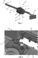
- the tool driving assembly 180 comprises a turret 182 that is rotatably mounted to the third slew bearing 174 and through which the tool driving assembly 180 is rotatably mounted to the SCARA arm assembly 160.
- a set of trunnions 186 are used to rotatably mount the tool translating mechanism 188 to the turret 182, allowing to change the slope by rotating the tool 194 relative to the axis 225 passing through the trunnions 186.
- the tool driving assembly 180 also comprises a tool translating mechanism 184 allowing to move the tool 194 forward and backward. Accordingly, the front extremity 196 of the tool 194 may:
- the tool driving mechanism 184 is adapted to drive a tool 194 having at the front extremity 196 a spade-like blade 198 that is adapted, e.g., to skim, to clean, to mix molten metal in the furnace, and to push molten material into the furnace.
- the general configuration of the robotic system 120 is adapted for the tool 194, and more precisely the tool assembly reference point 235 and the front extremity 196 of the tool 194 to travel freely within the limits offered by the degrees of freedom of the robotic system 120, which broadens the area the tool 194 may operate in.
- the rear extremity 197 of the tool 194 can extend above components of the robotic system 120, including the SCARA second arm 176, and optionally at least some of the control cabinet 164, the battery cabinet 166 and the power cabinet 168 without hitting them. Accordingly, the robotic system 120 is designed to adopt a large range of operating positions and a broad reach.
- the configuration of the deck 152 and of the SCARA first arm 170 with cabinets 164, 166, 168 mounted to the SCARA first arm 170 allows a rotation range of at least, two hundred and seventy (270) degrees, and more preferably at least three hundred (300) degrees, and more preferably almost three hundred and sixty (360) degrees, distributed as one hundred and eighty (180) degrees in each direction of a neutral direction, around the rotation axis 210, thus relative to the platform 140, with the structure of the power artery travelling therein limiting the rotation as discussed further hereinafter.
- the dimensions of the SCARA arms 170, 176, the locations and dimensions of the slew bearings 154, 172, 174 and the height of the cabinets 164, 166, 168 connected to the SCARA first arm 170 are designed for providing the necessary clearance for the SCARA second arm 176 to preferably have a rotation range of at least, two hundred and seventy (270) degrees, and more preferably at least three hundred (300) degrees, and more preferably almost three hundred and sixty (360) degrees, distributed as one hundred and eighty (180) degrees in each direction of a neutral direction, around the rotation axis 215, with the structure of the power artery travelling therein limiting the rotation as discussed further hereinafter.
- Such rotation range allows to operate the robotic system 120 with a large range of operable positions of the tool assembly reference point 235 and the tool driving assembly 180 for reasons that are discussed hereinafter.
- the tool driving mechanism 184 is designed to preferably have a rotation range of at least, two hundred and seventy (270) degrees, and more preferably at least three hundred (300) degrees, and more preferably almost three hundred and sixty (360) degrees, distributed as one hundred and eighty (180) degrees in each direction of a neutral direction, around the rotation axis 220, with the structure of the power artery travelling therein limiting the rotation as discussed further hereinafter.
- Such rotation range allows the robotic system 120 to operate in a large range of operable positions for reasons that are discussed hereinafter.
- the tool 194 is designed to preferably have a rotation range extending below the horizontal up to minus thirteen (-30), minus fourty-five (-45) and even minus sixty (-60) degrees relative to the horizontal and a maximum elevation of at least zero (0), at least five (5), at least ten (10) and at least fifteen (15) degrees, with the latter values being obtained when the front extremity 196 of the tool 194 is elevated relative to its rear extremity 197, resulting from the rotation of the tool 194 around the rotation axis 225.
- Such rotation range allows to operate the robotic system 120 with a large range of operable positions for reasons that are discussed hereinafter.
- the tool driving assembly 180 is adapted to provide the necessary extent (aka reach) to the front extremity 196 of the tool 194 to reach all zones of the furnace when tending a furnace.
- the tool 194 further features the physical characteristics necessary to resist to the undergone forces and temperature resulting from furnace tending processes.
- the robotic system 120 also features a relatively small ground footprint in relation with the available reach of the tool 194. It also features a potential limited, relatively small, horizontal above ground footprint comprising the ground touched by the robotic system 120 and the ground area hovered by components of the robotic system 120 according to a plan view.
- the SCARA arm assembly 160 is in a compact configuration with the SCARA second arm 176 substantially aligned and above the SCARA first arm 170, and the tool driving assembly 180 aligned and configured to minimize the horizontal above ground footprint, e.g., the tool 194 retracted to an about-central position depicted on Fig. 1 , the above ground footprint is minimized.
- the robotic system 120 in that compact configuration, features a balanced weight easing displacement and optimizing stability of the robotic system 120 for its displacement by an AMR 130. It may however extend to a greater above ground footprint when configured for the tool driving assembly 180 to adopt its maximum reach.
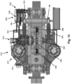
- the robotic system 120 comprises a powering assembly 280, comprising the cabinets 164, 166, 168, and a fluid reservoir 169.
- the powering assembly 280 is fixedly mounted to the SCARA first arm 170, rotating with the SCARA first arm 170 relative to the platform 140.
- the power cabinet comprises a hydraulic pump 282, preferably a variable displacement hydraulic pump, a kidney loop (not depicted) powered by, preferably, a fix displacement hydraulic pump (not depicted), and other electric and hydraulic components involved in powering and controlling the robotic system 120. Such components would be understandable by one person skilled in the art.
- the control cabinet 164 houses the controller assembly 112.
- the powering assembly 280 are mounted substantially close to the first slew bearing 154, generally distant to the second slew bearing 172.
- the powering assembly 280 is designed to provide counterweight against the weight of the parts of the robotic system 120 mounted to the second slew bearing 172 and thus balancing weight distribution over the platform 140 and decreasing dead load exerted over the first slew bearing 154.
- the hydraulic pump powering driving assemblies e.g., driving assembly 180
- the hydraulic pump powering driving assemblies is a variable displacement pump 282.
- a kidney loop designed for filtering the hydraulic fluid and cooling the hydraulic fluid, is powered, preferably, by a fix displaced pump.
- dynamic cooling components are limited to a minimum.
- a fan 284 is mounted to the rear face of the rearmost cabinet 168, cooling off hydraulic fluid circulating in the kidney loop about the fan 284.
- cooling vents are fluidly connecting side-located powering assembly 280.
- the battery cells 167 are isolated from the environment, or are cooled off through a distinct fan and filtering subsystem.
- the hydraulic fluid reservoir 169 is mounted rear to the SCARA first arm 170, with a hydraulic power cabinet 168 mounted rear to it.
- the variable displacement pump 282 powering the hydraulic circuit, with the battery cells 167 powering the hydraulic pump 282 and driving assemblies as is explained hereinafter.
- the controller assembly 112 is also powered by the battery cells 167 and is designed to control the operation of the hydraulic pump 282, the kidney loop hydraulic pump, and other components such valves, an image capture system, automation components, etc.
- the SCARA arm assembly 160 features an internal passageway 290 connecting the SCARA first arm 170 close to the first slew bearing 154 to the tool driving assembly 180 through the second slew bearing 172 and the third slew bearing 192, partially depicted through the longitudinal cross-section of the SCARA second arm 176 depicting a power artery 300 comprising hydraulic tubing 306 and a cable assembly 308, the latter comprising one or more command cables 318 and electric (powering) cables 319.
- the power artery 300 may split for 'local' needs providing a power vein 310 comprising at least one of, but usually all of the hydraulic tubing, the electric cables and command cable with the power artery 300 continuing its path past the split power vein 310.
- the power artery 300 extends in the passageway 290, transmitting power and instructions to driving assemblies, e.g., driving assembly 178 and the tool driving assembly 180, with power veins 310 splitting from the power artery 300 to connect to a driving assembly when appropriate, e.g., through openings in a side wall of the SCARA arm assembly 160.
- driving assemblies e.g., driving assembly 178 and the tool driving assembly 180
- power veins 310 splitting from the power artery 300 to connect to a driving assembly when appropriate, e.g., through openings in a side wall of the SCARA arm assembly 160.
- the hydraulic pump 282 Fig. 10
- the hydraulic pump 282 generates hydraulic power for the needs of and transmission by the power artery 300, with the different components connected to the power artery 300 tapping power therefrom when needed. Therefore, the hydraulic power cabinet 168 operates relatively independently from the individual power needs of the driving assemblies.
- the hydraulic pump 282 generates hydraulic power based on global power requirement, e.g., based on monitored pressure, with the driving assemblies tapping in on demand.
- hydraulic power is distributed to the rotational driving assemblies 178', 178".
- the power artery 300 extends in the passageway 290, through the second slew bearing 172 and third slew bearing 192 to another driving assembly 178′′′, and the tool driving assembly 180.
- the power artery 300 is to maintain operation with the passageway 290 having a changing configuration as the SCARA arm assembly 160 flexes, regardless of relative angles.
- the power artery 300 also extends upstream through the first slew bearing 154 to power the driving assembly 177 comprising the hydraulic actuators 144 associated with the scissor legs 142.
- the power artery 300 extends through second slew bearing 172 and the third slew bearing 192.
- the power artery 300 is designed to power the driving assemblies 181, 183 driving movements of the tool 194.
- the power artery may be split once or may times into one or more local power veins comprising at least one of a hydraulic tubing connected to and fed by the power artery, a command cable, and/or electric cables.
- a command cable part of the power vein
- Alternative embodiments with additional driving assemblies, sensors or other components can thus be connected to through a power vein without departing from the scope of the present description.
- FIG. 12 an exemplary extent of a power artery 300 and a powered driving assembly 180 are depicted.
- the depicted rotational driving assembly 178" controls rotation of the SCARA second arm 176 (not shown on Fig. 12 ) relative to the SCARA first arm 170.
- the power artery 300 extends in the passageway 290, with the hydraulic tubing extending through a rotary hub 302 comprising a core portion 304 and a barrel portion 305 mounted around the core portion 304.
- Inlet(s) 312 and outlet(s) 314 are distributed around the circumference for of the core portion 304 to be in fluid connection with the barrel portion 305 over 360 degrees, thereby having hydraulic fluid circulation in the power artery 300 regardless of the flexion of the SCARA arm assembly. Inlet(s) 312 and outlet(s) 314 present on the barrel portion 305 for the continuation of the fluid tubing in the next arm. Structurally, the core portion 304 is fixedly mounted to the SCARA first arm 170 and the barrel portion 305 is fixedly mounted to the SCARA second arm, rotating with the SCARA second arm 176, and allowing further extension of the hydraulic portion of the power artery 300 in the passageway 290 extending in the SCARA arm assembly.
- the cable assembly 324 of the second power artery 300 is mounted to a chain 328 guiding the course of the cable assembly 324 in all angles the SCARA second arm may adopt relative to the SCARA first arm 170 within the defined limits, preferably between about 180 degrees in one direction and 180 degrees in the opposed direction.
- the upstream ends of the chain 328 and of the cable assembly 324 are fixedly mounted to the SCARA first arm 170.
- the downstream ends are fixedly mounted to the SCARA second arm, exerting a rotation of the chain 328 and cable assembly 324 along the rotation the SCARA second arm.
- the power artery 300 features a joint assembly able to respond to flexion of the joint of the articulated SCARA arm assembly.
- the chain 328 features a series of links, aka frame connectors, rotatable relative to each other up to a limit angle, limiting flexion thereof to a minimum radius of curvature of the chain and of the cable assembly 324 set therein high enough to limit wear.
- the flexibility of the chain 328 and cable assembly 324 further prevents the cable assembly 324 from premature wear that would occur if the cable assembly 324 was undergoing twisting. It further allows the chain 328 and cable assembly 324 to wrap to one side or the other of the base of the rotary hub 302 as the SCARA second arm rotates in one direction or the other relative to the SCARA first arm 170.
- the driving assembly 178 designed for controlling the rotation of the SCARA second arm relative to the SCARA first arm 170, consists in a controlled zero-lap valve 332 having no-limit positions powered by the electric cables, a pair of hydraulic actuators 334 connected to the control valve 332, and a sensor 336, e.g., a position sensor or an angular sensor.
- the control valve 332 Based on a target position signal transmitted to the control valve 332 through the command cable of the power vein, the control valve 332 taps into the available hydraulic power and feeds hydraulic power to the paired hydraulic actuators 334 connecting the SCARA second arm to the SCARA first arm 170.
- the hydraulic actuators 334 thereby apply a torque resulting in rotation of the SCARA second arm.
- the sensor 336 connected to the control valve 332, provides continuous feedback to the control valve 332 on the actual angle of the SCARA second arm 176 relative to the SCARA first arm 170, allowing the control valve 332 to perform local control of rotation, aka local feedback loop, based on received target position and a locally-fed feedback position signal.
- control valve 332 of the driving assembly 178 is a Pressure and flow (P ⁇ Q) control valve designed to modulate operation in view of variable hydraulic pressure and flow provided through the feeding power vein.
- P ⁇ Q Pressure and flow
- the hydraulic actuators 334 consists in rotary actuators 394 each driving the shaft of a worm screw 397 (hidden in the casing 395 ) that engages a worm wheel 396 mounted to the component, e.g., the other arm, to drive the rotation.
- rotation about vertical axis 210, 215, Fig. 4 are subject to mechanical brakes 399 locking the shafts of the worms screws 397 against rotation, with the mechanical brakes 399 being activated once the target position is reached.
- control valve 332 and sensor 336 allows to operate without a mechanically imposed reference angle such as end-or-course of hydraulic actuators. Such realization provides additional flexibility, easier configuration and faster system responses.
- the design is done such as placing hydraulic tubing that is out of the passageway 290 when possible in a shielded position, whereby having, e.g., the structure of the SCARA arm shielding the hydraulic tubing from the heat of the furnace.
- a similar rotational driving assembly 178' comprising a control valve 332 combined with a pair of hydraulic actuators 334 and a sensor 336 is similarly used for the rotation of the SCARA first arm 170 relative to the platform 140.
- a similar driving assembly 178′′′ comprising a control valve 332 combined with a pair of hydraulic actuators 334 and a sensor 336 is similarly used for the rotation of the tool driving assembly 180 relative to the SCARA second arm 176.
- the robotic system 120 preferably comprise one or more thermal sensors 115 adapted to participate in monitoring the operating conditions of the robotic system 120.
- the slope of the tool translating mechanism 188 is driven by driving assembly 350 comprising a control valve 352, a sensor 356 and hydraulic actuators 354.
- the control valve 352 comprising an integrated controller dedicated for controlling movements relative to an axis, with the control valve 352 being an integrated axis controller directional valve, is mounted with a thermal shield (not shown) thermally insulating the control valve 352 from the heat of the furnace.
- the control valve 352, powered by a power vein, is powering the pair of cooperating hydraulic actuators 354 generating rotation of the tool 194 relative to the trunnions 186.
- the control valve 352 controls the slope of the tool 194.
- a controllable one-way valve 358 is further part of the driving assembly 350, being able to controllably lock the tool 194 in a desired slope angle.
- the tool translating mechanism 188 is for its part driven by a driving assembly 370 comprising a zero-lap valve 372, a sensor 374 and a hydraulic motor 376 adapted to drive a shaft 382 on which is mounted a driving cogwheel 384.
- a chain (not depicted) is anchored to the top face of the tool 194 frontward and rearward of the translatable portion of the tool 194. Through a rotation of the cogwheel 384, causing relative displacement of the chain, the tool translating mechanism 188 is designed to move forward and backward the tool 194. It is to be noted that leading cogwheels 386, 388 are present frontward and rearward of the driving cogwheel 386.
- the lead cogwheels 386, 388 are designed to maintain tension of the chain and to prevent misalignment of the chain from resulting is potential derailing.
- a rotative hydraulic motor 376 drives the drive shaft 382, driving the driving cogwheel 384.
- the sensor 374 connected to the zero-lap valve 372 provide continuous feedback on the current extension of the tool 194.
- control of the elevation of the platform, of the orientation of the SCARA first arm, and of the orientation of the SCARA second arm allows to fix in space the tool assembly reference point 235, Fig. 6 .
- Control of the orientation of the tool driving assembly, of the slope of the tool, and of the longitudinal displacement of the tool allows to control location and displacement of the spade-like blade 198, Fig. 7 .
- the combination of these controls provide a virtual expandable operation sphere having a movable center. Programming and controls are designed in that operational perspective.
- portions of hydraulic tubing 390 not protected by thermal shields 392 comprises a) rigid metallic tubing that offer appropriate protection against heat and are appropriate radiating characteristics preventing the circulating fluid to overheat; and b) flexible tubing that is covered with protective material, namely a silicon jacket, in other words a material comprising a fabric with a silicon cover layer designed to cover the flexible tubing, and further wrapped in a reflecting material, namely a aluminized fabric, with the combination limiting heat absorption and having desired reflective characteristics.
- the oil used in the hydraulic system is a fire retardant oil, and preferably Shell Naturelle S2 Hydraulic Fluid 46 TM .
- the single variable displacement pump and power artery configuration of the robotic system 120 provides the necessary power with limited number of tubing and cables.
- subsystems of the robotic system 120 are adapted to face variable available hydraulic power, with the subsystems simply reaching desired positions faster or slower based on the available hydraulic power.
- the robotic system 120 comprises a one or more cameras 400 and/or other image/distance capturing components (e.g., radars, Lidars) that are connected to the control assembly 112, and that are used as data source by the automatization program stored in memory and operated by the robotic system 120 to perform autonomous operations.
- image/distance capturing components e.g., radars, Lidars
- at least two cameras 400, or other image capturing components, located at distinct positions distant from each other are used to get a 3D view of the furnace and its content.
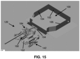
- FIG. 15 depicts the robotic system 120 initially moved at a station in front of a furnace 100.
- the robotic system 120 is initially in a transport position, with the legs 142 extended.
- the deck 152 is lowered, stabilized, and leveled to adopt the operating position wherein the operating height is set relative to the sill of the furnace for the robotic system 120 to be ready to begin the furnace tending process.
- the SCARA arm assembly 160 is deployed such as adjusting the tool assembly reference point 235 , Fig. 6 , of the tool 194.
- Fig. 18 illustrates an example of configuration wherein the spade-like blade 198 can reach the end wall 102 of the furnace 100, the spade-like blade 198 parallel to the end wall 102 and about the left wall 104.
- Fig. 19 illustrates an example of configuration wherein the spade-like blade 198 can reach the end wall 102 of the furnace 100 about the right wall 106, the flat wall of spade-like blade 198 distant from the SCARA arm assembly 160 parallel to the end wall 102. Accordingly, by displacing the tool assembly reference point 235, Fig.
- the spade-like blade 198 at the front extremity 196 of the tool 194 may be positioned anywhere inside the furnace 100, the spade-like blade 198 being able to be placed parallel to, thus able to scrape, the end wall 102 of the furnace 100.
- the spade-like blade 198 of the tool 194 may be used for different functions, comprising e.g., a surface scraping function for cleaning the walls 104, 106, and the floor of the furnace 100; a travelling function in which the spade-like blade 198 travels above the molten metal present in the furnace; a mixing function of the molten metal; and a skimming function during which the spade-like blade 198 controllably penetrates the surface of the molten metal and rakes out dross from its surface.
- a surface scraping function for cleaning the walls 104, 106, and the floor of the furnace 100
- a travelling function in which the spade-like blade 198 travels above the molten metal present in the furnace
- a mixing function of the molten metal a mixing function of the molten metal
- a skimming function during which the spade-like blade 198 controllably penetrates the surface of the molten metal and rakes out dross from its surface.
- the tool assembly reference point 235 can take a range of positions, comprising a range of transversal (left/right) locations, and longitudinal (front/rear) positions, thus relatively close or distant to the door sill of the furnace 100.
- FIG. 21 an example of a projection of a hovering path 250 in a horizontal plane of the front extremity of the tool is illustrated.
- the spade-like blade of the tool can hover any location in the furnace 100.
- the spade-like blade can be in an operative angle in which the blade may be operated with the robotic system 120, Fig. 1 , remaining stationary, aka at the same station standing on the ground and without having an AMR moving the robotic system 120 during the furnace tending process.
- the robotic system 120 comprises a controller assembly 112, house in the control cabinet 164, e.g., Fig. 6 , on which is connected a control panel 113 comprising security components (e.g., push buttons and controls adapted to cut off power and menage security features).
- the controller assembly 112 is connected to the driving assemblies through the communication cable.
- the controller assembly 112 operates according to an automatization program and parameters, wherein the automatization program and parameter may, for instance, result from a program learning process during which visual data acquired through, e.g., a 3D imaging subsystem 117 comprising, e.g., a camera 400 or other image capturing component, with the data being consolidated by the controller assembly 112.
- the e.g., camera 400 is selected to be compatible with detection of objects in a high-temperature environment, aka precision of detection with objects being at about 800-900 degrees Celsius.
- a structured-light 3D scanner is used to collect data.
- a laser projection for furnace imaging is used to collect data.
- a detection component is protected by a movable thermal shield, with control displacement of the thermal shield providing intermittent field of view of the furnace 100 to the imaging subsystem 117.
- the imaging subsystem 117 comprises at least one dynamically cooled camera or detection component, used with or without transparent thermal shielding.
- the controller assembly 112 is further adapted to consolidate the images into data, actions, and parameters (e.g., positions, forces) according to which the robotic system 120 is operated during a furnace tending process. Accordingly, once the learning process of automatization program is completed, the robotic system 120 is adapted to be able to respond automatically to furnace conditions with appropriate actions based on live detections performed by the imaging subsystem 117 alone or in combination with data provided by other sensor(s).
- data, actions, and parameters e.g., positions, forces
- the present description contemplates both stationary and mobile robotic systems, with the robotic systems being either autonomous or requiring external power to move; and methods of performing a furnace tending process using that robotic system, regardless of the robotic system remaining stationary throughout the furnace tending process or being moved during the furnace tending process.
- the present contemplates robotic systems being powered though a power cable; or preferably robotic systems comprising battery cells permitting to the robotic system to be autonomous in relation with power during furnace tending processes.
- robotic systems preferably comprise safety laser scanners, not depicted, scanning the vicinity, aka a danger zone, surrounding the robotic system for presence and movement, particularly human presence.
- the laser scanners are connected to the controller assembly itself programmed, for safety reasons, to stop any movement upon detection of human presence, thereby preventing the robotic system from hitting someone.
Landscapes
- Engineering & Computer Science (AREA)
- Robotics (AREA)
- Mechanical Engineering (AREA)
- Manipulator (AREA)
Claims (15)
- Robotersystem (120) umfassend:eine eigenständige Plattform (140), die zwischen Stationen bewegt werden kann;eine artikulierte Armbaugruppe, die auf der Plattform (140) um eine erste Achse (210) rotierbar montiert ist, wobei die artikulierte Armbaugruppe mindestens ein flexibles Gelenk durch eine zweite Achse (215) aufweist, und eine dritte Achse (220) weiter zur ersten Achse (210) hin als zum Gelenk, wobei die erste Achse (210) und die zweite Achse (215) parallel zueinander liegen;eine Werkzeugantriebsbaugruppe (180), die auf der artikulierten Armbaugruppe um die dritte Achse (220) rotierbar montiert ist;Energieversorgungsbaugruppe (280), die auf der artikulierten Armbaugruppe fest montiert ist, wodurch die Energieversorgungsbaugruppe (280) mit der artikulierten Armbaugruppe um die erste Achse (210) rotierbar ist;Antriebsbaugruppen (183) (181) zum Antreiben einer ersten Bewegung der artikulierten Armbaugruppe relativ zur ersten Achse (210), Antreiben einer zweiten Bewegung der artikulierten Armbaugruppe relativ zur zweiten Achse (215), Antreiben einer dritten Bewegung der Werkzeugantriebsbaugruppe (180) des Werkzeugs (194) relativ zur dritten Achse (220) und Antreiben der Werkzeugantriebsbaugruppe (180);wobei Antriebsbaugruppen (183) (181) mit der Energieversorgungsbaugruppe (280) verbunden sind.
- Robotersystem (120) nach Anspruch 1, wobei die Energieversorgungsbaugruppe (280) eine hydraulische Antriebspumpe umfasst.
- Robotersystem (120) nach Anspruch 1, wobei die artikulierte Armbaugruppe eine SCARA-Armbaugruppe (160) ist, die Arme (170) (176) umfasst, die über einen Drehkranz (172) rotierbar aneinander montiert sind.
- Robotersystem (120) nach Anspruch 3, wobei die SCARA-Armbaugruppe (160) einen Durchgang (290) umfasst, der sich durch die Arme (170) (176) und den Drehkranz (172) erstreckt.
- Robotersystem (120) nach Anspruch 4, ferner umfassend eine Versorgungsarterie (300), die sich durch den Durchgang (290) erstreckt, wobei die Versorgungsarterie (300) Mittel zum Übertragen von hydraulischer Leistung, ein Befehlskabel (318) und ein elektrisches Versorgungskabel (319) umfasst, wobei die Versorgungsarterie (300) mit mindestens einer der Antriebsbaugruppen (183) (181) verbunden ist.
- Robotersystem (120) nach Anspruch 1, wobei die Werkzeugantriebsbaugruppe (180) rotierbar auf der artikulierten Armbaugruppe montiert ist, wobei die Werkzeugantriebsbaugruppe (180) ein Werkzeug (194) gemäß mindestens zwei Freiheitsgraden antreibt.
- Robotersystem (120) nach Anspruch 1, wobei die eigenständige Plattform (140) ausziehbare Beine (142), zum Überwachen der Stabilität der Plattform (140) ausgelegte Überwachungskomponenten und mit den Beinen (142) verbundene Antriebskomponenten zum steuerbaren Anpassen der Auszuglängen der Beine (142) zum Beibehalten der Stabilität der Plattform (140) umfasst.
- Robotersystem (120) nach Anspruch 1, wobei mindestens eine der Antriebsbaugruppen (183) (181) ein mit hydraulischer Leistung versorgtes Steuerventil (352) (332), das zum Empfangen eines Zielpositionsbefehls angepasst ist, einen hydraulischen Aktuator (334) verbunden mit dem Steuerventil (352) (332) und einen Sensor (336) ausgelegt zum Übertragen eines sich mit dem Betrieb des Aktuators (334) änderndes Positionssignals an das Steuerventil (352) (332) umfasst, wobei das Steuerventil (352) (332) zum Vergleichen des Zielpositionsbefehls mit dem Positionssignal und dementsprechend zum Übertragen von hydraulischer Leistung an den hydraulischen Aktuator (334) angepasst ist.
- Robotersystem (120) nach Anspruch 2, wobei die hydraulische Antriebspumpe aus einer variablen Verdrängerpumpe (282) besteht, wobei das Robotersystem (120) ferner ein Nebenstromsystem und eine feste Verdrängerpumpe, die im Zusammenwirken mit dem Nebenstromsystem arbeitet, umfasst.
- Robotersystem (120) nach Anspruch 9, wobei die Energieversorgungsbaugruppe (280) einen Ventilator (284) umfasst, der zum Herunterkühlen von Flüssigkeit, die im Nebenstromsystem zirkuliert, angepasst ist.
- Robotersystem (120) nach Anspruch 1, wobei die Energieversorgungsbaugruppe (280) Akkuzellen (167) umfasst.
- Robotersystem (120) nach Anspruch 1, wobei die Energieversorgungsbaugruppe (280) auf der artikulierten Armbaugruppe mit Abstand zur dritten Achse (220) montiert ist, wodurch die Energieversorgungsbaugruppe (280) zumindest teilweise tote Last, die von der Werkzeugantriebsbaugruppe (180) erzeugt wird, ausgleicht.
- Robotersystem (120) nach Anspruch 1, wobei mindestens eines der Folgenden zutrifft:die artikulierte Armbaugruppe ist angepasst, über mindestens 270 Grad gebeugt zu werden; unddie artikulierte Armbaugruppe ist angepasst, relativ zur Plattform (140) über mindestens 270 Grad zu rotieren.
- Robotersystem (120) nach Anspruch 3, ferner umfassend ein steuerbares Einwegventil (358) verbunden mit einem hydraulischen Aktuator (334), wobei das steuerbare Einwegventil (358) als eine hydraulische Bremse für eine der Antriebsbaugruppen (183) (181) arbeitet.
- Robotersystem (120) nach Anspruch 3, ferner umfassend eine Steuerungsbaugruppe (112) und ein Abbildungssubsystem (117), das eine Bilderfassungskomponente (400) umfasst, wobei das Robotersystem (120) ein Automationsprogramm umfasst, das für autonomen Betrieb auf der Basis von mindestens einem Bild, das vom Abbildungssubsystem (117) erfasst wird, und dem Automationsprogramm angepasst ist.
Applications Claiming Priority (1)
| Application Number | Priority Date | Filing Date | Title |
|---|---|---|---|
| US202263315819P | 2022-03-02 | 2022-03-02 |
Publications (3)
| Publication Number | Publication Date |
|---|---|
| EP4238710A1 EP4238710A1 (de) | 2023-09-06 |
| EP4238710C0 EP4238710C0 (de) | 2024-12-04 |
| EP4238710B1 true EP4238710B1 (de) | 2024-12-04 |
Family
ID=84520037
Family Applications (1)
| Application Number | Title | Priority Date | Filing Date |
|---|---|---|---|
| EP22213226.8A Active EP4238710B1 (de) | 2022-03-02 | 2022-12-13 | Robotersystem für aluminiumofenoperationen |
Country Status (1)
| Country | Link |
|---|---|
| EP (1) | EP4238710B1 (de) |
Families Citing this family (2)
| Publication number | Priority date | Publication date | Assignee | Title |
|---|---|---|---|---|
| CN119347736A (zh) * | 2024-11-18 | 2025-01-24 | 北京朗信智能科技有限公司 | 料面处理机器人 |
| CN120287337B (zh) * | 2025-04-22 | 2025-11-21 | 北京科技大学 | 一种炉前作业机器人系统及其模块化设计方法 |
Family Cites Families (4)
| Publication number | Priority date | Publication date | Assignee | Title |
|---|---|---|---|---|
| JPS5969283A (ja) * | 1982-10-12 | 1984-04-19 | 豊田工機株式会社 | 水平多関節型ロボツト |
| US5634377A (en) * | 1994-03-09 | 1997-06-03 | Sony Corporation | Articulated robot |
| US10751888B2 (en) * | 2018-10-04 | 2020-08-25 | Advanced Intelligent Systems Inc. | Manipulator apparatus for operating on articles |
| CN114730728A (zh) * | 2019-11-01 | 2022-07-08 | 朗姆研究公司 | 具有重力场传感器的晶片搬运机械手 |
-
2022
- 2022-12-13 EP EP22213226.8A patent/EP4238710B1/de active Active
Also Published As
| Publication number | Publication date |
|---|---|
| EP4238710A1 (de) | 2023-09-06 |
| EP4238710C0 (de) | 2024-12-04 |
Similar Documents
| Publication | Publication Date | Title |
|---|---|---|
| US20240198536A1 (en) | Robot and automated guided vehicle combination for aluminum furnace operations | |
| EP4238710B1 (de) | Robotersystem für aluminiumofenoperationen | |
| US4697239A (en) | Automated installation for processing large objects | |
| US11219916B2 (en) | Surface treatment system for large object | |
| EP3903941B1 (de) | System und verfahren zum tauschen von auskleidungen, deren konfiguration das automatisierte entfernen und einsetzen von auskleidungen einer zum erzschleifen verwendeten mühle ermöglicht | |
| US20200198154A1 (en) | Method of Controlling Surface Treatment System | |
| TW201023998A (en) | Automation concept for a metallurgical plant or rolling mill | |
| CN116141510B (zh) | 一种多自由度联动式凿毛机 | |
| US20230064546A1 (en) | System and method for changing a mill liner, configured to allow the fully automated and robotic manipulation of the method | |
| KR20150125934A (ko) | 정지된 마스트 및 회전식 헤드를 가진 작업 장치 | |
| CN115885169A (zh) | 可用于钢铁工业的熔化炉的检查设备和方法 | |
| US20250207861A1 (en) | Apparatus for inspecting and/or restoring a hostile environment and corresponding method | |
| CN117300761A (zh) | 关节轴承类研磨加工和检测一体设备及其控制方法 | |
| US4786250A (en) | Installation for evacuating emanations in the taphole region of shaft furnaces | |
| Raimondi | The JET experience with remote handling equipment and future prospects | |
| RU222567U1 (ru) | Мобильное устройство для обработки крупногабаритных объектов | |
| RU222569U1 (ru) | Мобильное устройство для обработки крупногабаритных объектов | |
| CN120116234B (zh) | 用于高压带电设备螺栓紧固的协作机器人作业器 | |
| CN220902147U (zh) | 移动式等离子切割装置 | |
| KR102326292B1 (ko) | 전로 내화물 측정장치 | |
| CN218195156U (zh) | 一种设备巡检机器人 | |
| CN218208680U (zh) | 一种视觉旋转云台机构 | |
| CN219266110U (zh) | 一种用于固定式电炉内衬的检测设备及系统 | |
| KR20240048399A (ko) | 침적관의 내화물 마모상태 무인자동검측시스템 | |
| US20250170729A1 (en) | Robot |
Legal Events
| Date | Code | Title | Description |
|---|---|---|---|
| PUAI | Public reference made under article 153(3) epc to a published international application that has entered the european phase |
Free format text: ORIGINAL CODE: 0009012 |
|
| STAA | Information on the status of an ep patent application or granted ep patent |
Free format text: STATUS: THE APPLICATION HAS BEEN PUBLISHED |
|
| AK | Designated contracting states |
Kind code of ref document: A1 Designated state(s): AL AT BE BG CH CY CZ DE DK EE ES FI FR GB GR HR HU IE IS IT LI LT LU LV MC ME MK MT NL NO PL PT RO RS SE SI SK SM TR |
|
| STAA | Information on the status of an ep patent application or granted ep patent |
Free format text: STATUS: REQUEST FOR EXAMINATION WAS MADE |
|
| 17P | Request for examination filed |
Effective date: 20240306 |
|
| RBV | Designated contracting states (corrected) |
Designated state(s): AL AT BE BG CH CY CZ DE DK EE ES FI FR GB GR HR HU IE IS IT LI LT LU LV MC ME MK MT NL NO PL PT RO RS SE SI SK SM TR |
|
| GRAP | Despatch of communication of intention to grant a patent |
Free format text: ORIGINAL CODE: EPIDOSNIGR1 |
|
| STAA | Information on the status of an ep patent application or granted ep patent |
Free format text: STATUS: GRANT OF PATENT IS INTENDED |
|
| INTG | Intention to grant announced |
Effective date: 20240628 |
|
| GRAS | Grant fee paid |
Free format text: ORIGINAL CODE: EPIDOSNIGR3 |
|
| GRAA | (expected) grant |
Free format text: ORIGINAL CODE: 0009210 |
|
| STAA | Information on the status of an ep patent application or granted ep patent |
Free format text: STATUS: THE PATENT HAS BEEN GRANTED |
|
| AK | Designated contracting states |
Kind code of ref document: B1 Designated state(s): AL AT BE BG CH CY CZ DE DK EE ES FI FR GB GR HR HU IE IS IT LI LT LU LV MC ME MK MT NL NO PL PT RO RS SE SI SK SM TR |
|
| REG | Reference to a national code |
Ref country code: CH Ref legal event code: EP |
|
| REG | Reference to a national code |
Ref country code: DE Ref legal event code: R096 Ref document number: 602022008393 Country of ref document: DE |
|
| REG | Reference to a national code |
Ref country code: IE Ref legal event code: FG4D |
|
| U01 | Request for unitary effect filed |
Effective date: 20250102 |
|
| U07 | Unitary effect registered |
Designated state(s): AT BE BG DE DK EE FI FR IT LT LU LV MT NL PT RO SE SI Effective date: 20250114 |
|
| U20 | Renewal fee for the european patent with unitary effect paid |
Year of fee payment: 3 Effective date: 20250218 |
|
| PG25 | Lapsed in a contracting state [announced via postgrant information from national office to epo] |
Ref country code: HR Free format text: LAPSE BECAUSE OF FAILURE TO SUBMIT A TRANSLATION OF THE DESCRIPTION OR TO PAY THE FEE WITHIN THE PRESCRIBED TIME-LIMIT Effective date: 20241204 |
|
| PG25 | Lapsed in a contracting state [announced via postgrant information from national office to epo] |
Ref country code: ES Free format text: LAPSE BECAUSE OF FAILURE TO SUBMIT A TRANSLATION OF THE DESCRIPTION OR TO PAY THE FEE WITHIN THE PRESCRIBED TIME-LIMIT Effective date: 20241204 |
|
| PG25 | Lapsed in a contracting state [announced via postgrant information from national office to epo] |
Ref country code: NO Free format text: LAPSE BECAUSE OF FAILURE TO SUBMIT A TRANSLATION OF THE DESCRIPTION OR TO PAY THE FEE WITHIN THE PRESCRIBED TIME-LIMIT Effective date: 20250304 |
|
| PG25 | Lapsed in a contracting state [announced via postgrant information from national office to epo] |
Ref country code: GR Free format text: LAPSE BECAUSE OF FAILURE TO SUBMIT A TRANSLATION OF THE DESCRIPTION OR TO PAY THE FEE WITHIN THE PRESCRIBED TIME-LIMIT Effective date: 20250305 |
|
| PG25 | Lapsed in a contracting state [announced via postgrant information from national office to epo] |
Ref country code: RS Free format text: LAPSE BECAUSE OF FAILURE TO SUBMIT A TRANSLATION OF THE DESCRIPTION OR TO PAY THE FEE WITHIN THE PRESCRIBED TIME-LIMIT Effective date: 20250304 |
|
| PG25 | Lapsed in a contracting state [announced via postgrant information from national office to epo] |
Ref country code: SM Free format text: LAPSE BECAUSE OF FAILURE TO SUBMIT A TRANSLATION OF THE DESCRIPTION OR TO PAY THE FEE WITHIN THE PRESCRIBED TIME-LIMIT Effective date: 20241204 |
|
| PG25 | Lapsed in a contracting state [announced via postgrant information from national office to epo] |
Ref country code: PL Free format text: LAPSE BECAUSE OF FAILURE TO SUBMIT A TRANSLATION OF THE DESCRIPTION OR TO PAY THE FEE WITHIN THE PRESCRIBED TIME-LIMIT Effective date: 20241204 |
|
| PG25 | Lapsed in a contracting state [announced via postgrant information from national office to epo] |
Ref country code: IS Free format text: LAPSE BECAUSE OF FAILURE TO SUBMIT A TRANSLATION OF THE DESCRIPTION OR TO PAY THE FEE WITHIN THE PRESCRIBED TIME-LIMIT Effective date: 20250404 |
|
| PG25 | Lapsed in a contracting state [announced via postgrant information from national office to epo] |
Ref country code: SK Free format text: LAPSE BECAUSE OF FAILURE TO SUBMIT A TRANSLATION OF THE DESCRIPTION OR TO PAY THE FEE WITHIN THE PRESCRIBED TIME-LIMIT Effective date: 20241204 |
|
| PG25 | Lapsed in a contracting state [announced via postgrant information from national office to epo] |
Ref country code: CZ Free format text: LAPSE BECAUSE OF FAILURE TO SUBMIT A TRANSLATION OF THE DESCRIPTION OR TO PAY THE FEE WITHIN THE PRESCRIBED TIME-LIMIT Effective date: 20241204 |
|
| PG25 | Lapsed in a contracting state [announced via postgrant information from national office to epo] |
Ref country code: MC Free format text: LAPSE BECAUSE OF FAILURE TO SUBMIT A TRANSLATION OF THE DESCRIPTION OR TO PAY THE FEE WITHIN THE PRESCRIBED TIME-LIMIT Effective date: 20241204 |
|
| PLBE | No opposition filed within time limit |
Free format text: ORIGINAL CODE: 0009261 |
|
| STAA | Information on the status of an ep patent application or granted ep patent |
Free format text: STATUS: NO OPPOSITION FILED WITHIN TIME LIMIT |
|
| PG25 | Lapsed in a contracting state [announced via postgrant information from national office to epo] |
Ref country code: IE Free format text: LAPSE BECAUSE OF NON-PAYMENT OF DUE FEES Effective date: 20241213 |
|
| 26N | No opposition filed |
Effective date: 20250905 |
|
| U20 | Renewal fee for the european patent with unitary effect paid |
Year of fee payment: 4 Effective date: 20251124 |