EP4238697A1 - Adjustable stroke device - Google Patents
Adjustable stroke device Download PDFInfo
- Publication number
- EP4238697A1 EP4238697A1 EP23158102.6A EP23158102A EP4238697A1 EP 4238697 A1 EP4238697 A1 EP 4238697A1 EP 23158102 A EP23158102 A EP 23158102A EP 4238697 A1 EP4238697 A1 EP 4238697A1
- Authority
- EP
- European Patent Office
- Prior art keywords
- stroke
- mounting assembly
- shaft
- housing
- counterweight
- Prior art date
- Legal status (The legal status is an assumption and is not a legal conclusion. Google has not performed a legal analysis and makes no representation as to the accuracy of the status listed.)
- Pending
Links
- 230000007246 mechanism Effects 0.000 claims abstract description 27
- 230000009021 linear effect Effects 0.000 claims description 3
- 230000008878 coupling Effects 0.000 claims 3
- 238000010168 coupling process Methods 0.000 claims 3
- 238000005859 coupling reaction Methods 0.000 claims 3
- 230000000712 assembly Effects 0.000 abstract description 2
- 238000000429 assembly Methods 0.000 abstract description 2
- 239000003973 paint Substances 0.000 description 11
- 239000000872 buffer Substances 0.000 description 7
- 238000005498 polishing Methods 0.000 description 4
- 230000007547 defect Effects 0.000 description 3
- 230000009977 dual effect Effects 0.000 description 3
- 238000009987 spinning Methods 0.000 description 3
- 238000000034 method Methods 0.000 description 2
- 150000001875 compounds Chemical class 0.000 description 1
- 230000007812 deficiency Effects 0.000 description 1
- 238000012986 modification Methods 0.000 description 1
- 230000004048 modification Effects 0.000 description 1
- 239000001993 wax Substances 0.000 description 1
Images


Classifications
-
- B—PERFORMING OPERATIONS; TRANSPORTING
- B24—GRINDING; POLISHING
- B24B—MACHINES, DEVICES, OR PROCESSES FOR GRINDING OR POLISHING; DRESSING OR CONDITIONING OF ABRADING SURFACES; FEEDING OF GRINDING, POLISHING, OR LAPPING AGENTS
- B24B23/00—Portable grinding machines, e.g. hand-guided; Accessories therefor
- B24B23/02—Portable grinding machines, e.g. hand-guided; Accessories therefor with rotating grinding tools; Accessories therefor
- B24B23/03—Portable grinding machines, e.g. hand-guided; Accessories therefor with rotating grinding tools; Accessories therefor the tool being driven in a combined movement
-
- B—PERFORMING OPERATIONS; TRANSPORTING
- B24—GRINDING; POLISHING
- B24B—MACHINES, DEVICES, OR PROCESSES FOR GRINDING OR POLISHING; DRESSING OR CONDITIONING OF ABRADING SURFACES; FEEDING OF GRINDING, POLISHING, OR LAPPING AGENTS
- B24B23/00—Portable grinding machines, e.g. hand-guided; Accessories therefor
- B24B23/02—Portable grinding machines, e.g. hand-guided; Accessories therefor with rotating grinding tools; Accessories therefor
- B24B23/028—Angle tools
-
- B—PERFORMING OPERATIONS; TRANSPORTING
- B24—GRINDING; POLISHING
- B24B—MACHINES, DEVICES, OR PROCESSES FOR GRINDING OR POLISHING; DRESSING OR CONDITIONING OF ABRADING SURFACES; FEEDING OF GRINDING, POLISHING, OR LAPPING AGENTS
- B24B23/00—Portable grinding machines, e.g. hand-guided; Accessories therefor
- B24B23/04—Portable grinding machines, e.g. hand-guided; Accessories therefor with oscillating grinding tools; Accessories therefor
-
- B—PERFORMING OPERATIONS; TRANSPORTING
- B24—GRINDING; POLISHING
- B24B—MACHINES, DEVICES, OR PROCESSES FOR GRINDING OR POLISHING; DRESSING OR CONDITIONING OF ABRADING SURFACES; FEEDING OF GRINDING, POLISHING, OR LAPPING AGENTS
- B24B41/00—Component parts such as frames, beds, carriages, headstocks
- B24B41/04—Headstocks; Working-spindles; Features relating thereto
- B24B41/042—Balancing mechanisms
-
- B—PERFORMING OPERATIONS; TRANSPORTING
- B24—GRINDING; POLISHING
- B24B—MACHINES, DEVICES, OR PROCESSES FOR GRINDING OR POLISHING; DRESSING OR CONDITIONING OF ABRADING SURFACES; FEEDING OF GRINDING, POLISHING, OR LAPPING AGENTS
- B24B47/00—Drives or gearings; Equipment therefor
- B24B47/10—Drives or gearings; Equipment therefor for rotating or reciprocating working-spindles carrying grinding wheels or workpieces
- B24B47/12—Drives or gearings; Equipment therefor for rotating or reciprocating working-spindles carrying grinding wheels or workpieces by mechanical gearing or electric power
-
- B—PERFORMING OPERATIONS; TRANSPORTING
- B24—GRINDING; POLISHING
- B24B—MACHINES, DEVICES, OR PROCESSES FOR GRINDING OR POLISHING; DRESSING OR CONDITIONING OF ABRADING SURFACES; FEEDING OF GRINDING, POLISHING, OR LAPPING AGENTS
- B24B55/00—Safety devices for grinding or polishing machines; Accessories fitted to grinding or polishing machines for keeping tools or parts of the machine in good working condition
-
- F—MECHANICAL ENGINEERING; LIGHTING; HEATING; WEAPONS; BLASTING
- F16—ENGINEERING ELEMENTS AND UNITS; GENERAL MEASURES FOR PRODUCING AND MAINTAINING EFFECTIVE FUNCTIONING OF MACHINES OR INSTALLATIONS; THERMAL INSULATION IN GENERAL
- F16H—GEARING
- F16H57/00—General details of gearing
- F16H57/02—Gearboxes; Mounting gearing therein
- F16H57/023—Mounting or installation of gears or shafts in the gearboxes, e.g. methods or means for assembly
-
- F—MECHANICAL ENGINEERING; LIGHTING; HEATING; WEAPONS; BLASTING
- F16—ENGINEERING ELEMENTS AND UNITS; GENERAL MEASURES FOR PRODUCING AND MAINTAINING EFFECTIVE FUNCTIONING OF MACHINES OR INSTALLATIONS; THERMAL INSULATION IN GENERAL
- F16H—GEARING
- F16H57/00—General details of gearing
- F16H57/02—Gearboxes; Mounting gearing therein
- F16H2057/02034—Gearboxes combined or connected with electric machines
Definitions
- Rotary buffers are the fastest and most effective machine for removing paint defects in a controlled manner with good results.
- the drive unit used in a rotary buffer is directly connected to the pad and each one is in axial alignment with each other.
- the rotary buffer is commonly used to remove enough paint surrounding the scratches to make the surface level. Removing scratches, however, requires more skill and control of the machine than a typical hobbyist possesses. For this reason, rotary buffers are commonly avoided by average users as it is very easy to remove too much paint and damage the finish by causing swirl marks or by burning the paint.
- the stroke is determined by the offset between the driveshaft axis and the backing axis.
- a longer offset or stroke places the backing plate rotational axis farther away from the driveshaft axis. Multiplying the offset by two produces the stroke diameter.
- the "stroke” is, therefore, a term that identifies the diameter of the path the backing plate travels as it orbits around the driveshaft.
- a large stroke machine delivers increased orbits per minute (OPM) of backing plate motion using the same rotations per minute (RPM), as the orbit of the backing plate and the pad around the drive shaft is increased.
- a large stroke also increases movement of the pad which helps spread out polishing compounds and treats a larger surface area. It also accomplishes more cutting action into the paint which allows for scratches and paint defects to be corrected.
- Small stroke machines typically only polish the paint and do not cut into it, and, therefore, are not able to remove surface defects.
- the counterweight portion is coupled with a base disk.
- the base disk is rotable with respect to the housing.
- the counterweight shaft assembly includes a bore to receive the stroke adjuster.
- the stroke adjuster includes a bore to receive the mounting assembly.
- the mounting assembly extends through the base disk to couple the workpiece attachment mechanism.
- the housing includes a ring gear meshing with a gear of the stroke adjuster drivetrain.
- the adjustable stroke device 30 includes a counterbalance assembly mechanism 34, a workpiece mounting assembly 36 and a stroke adjustment mechanism 40.
- a housing 42 covers the counterbalance assembly 34, workpiece mounting assembly 36 and stroke adjustment mechanism 40.
- the housing 42 defines a cavity that houses the elements.
- the counterweight 44 has an overall infinity shape with a pair of bores 52, 54.
- the bore 52 receives a bearing 56 of the stroke adjustment mechanism 40.
- the web 58 between the bores 52, 54, includes a threaded bore to receive a threaded portion 60 of the shaft 46.
- the plate 66 is circular shaped including a bore 68 to receive the stroke adjustment mechanism 40.
- the stroke adjustment mechanism 40 includes a hollow gear wheel 70 including teeth 72.
- the gear wheel 70 includes a shaft portion 74 projecting from the top of the gear wheel 70.
- the shaft portion 74 is received by the bearing 56 which is seated in the bore 52 of the counterweight portion 44.
- a circular base 76 is positioned into the bore of the plate 66.
- the base 76 includes an elliptical portion 78 that fits into an elliptical cutout 80 in the open end of the gear wheel 70.
- bores 82 extend thru the base to secure the base 76 with the plate 66.
- the gear wheel 70 includes a bore 84 that receives bearings 86 of the workpiece mounting assembly 36.
- the motor 12 is activated to rotate the pinion 18.
- the pinion 18 rotates the bevel gear 24.
- the bevel gear 24 keyed to shaft 46, rotates the counterbalance assembly 34.
- the plate 66 is rotated in the housing portion 98.
- the stroke adjustment mechanism 40 has its shaft 74 positioned in counterweight bore 52, via bearings 56.
- the gear wheel 70 is rotated by the ring gear 106 as the gear wheel 70 rotates and moves around the cavity.
- the plate 66 is secured to the gear wheel 70 which, in turn, positions the workpiece mounting assembly 36 that is positioned within the gear wheel 70.
- the stroke adjuster acts as a drivetrain automatically adjusting the mounting assembly stroke along the path illustrated in Fig. 9A .
Abstract
Description
- The present disclosure relates to random orbital devices including, but not limited to polishers, buffers, sanders and massagers.
- The present disclosure relates to an apparatus for automatically randomly alternating the stroke of a random orbital machine, such as, but limited to, polishing machines, sanding machines and massaging machines. This enables the user to have a defined random stroke of the random orbital machine.
- Polishing machines and sanding machines are routinely used in the automotive detailing industry and home building industry to correct imperfections in the paint or drywall and to apply polishes and waxes. There are three primary machines used, including rotary buffers, random orbital machines, and dual action machines. Each tool has its place, as the manner where the pad spins on each machine is unique and used for different purposes.
- Rotary buffers are the fastest and most effective machine for removing paint defects in a controlled manner with good results. The drive unit used in a rotary buffer is directly connected to the pad and each one is in axial alignment with each other. In order to correct paint scratches, the rotary buffer is commonly used to remove enough paint surrounding the scratches to make the surface level. Removing scratches, however, requires more skill and control of the machine than a typical hobbyist possesses. For this reason, rotary buffers are commonly avoided by average users as it is very easy to remove too much paint and damage the finish by causing swirl marks or by burning the paint.
- Random orbital machines were introduced in order to meet the needs of an average user, as they require less experience and control to operate. A random orbital machine uses a gear case that employs two unique mechanisms that move a pad attached to a backing plate. Unlike a rotary buffer, random orbital machines place the central rotational axis of the pad and the backing plate offset from the driveshaft of the machine. This offset is commonly referred to as the "stroke". As a result, the backing plate and pad orbit the driveshaft in a circular motion. At the same time, the pad randomly spins, as it is mounted on an idle bearing. This random spinning varies with pressure applied on the pad and is not directly powered. The result is a polishing action that will not burn or cut through the paint as it will not produce the heat from a powered spinning action. Random orbital machines are, therefore, much safer and dramatically less likely to cause swirls or burn through the paint.
- Similar to random orbital machines, dual action machines place the central rotational axis of the pad and the backing plate offset from the driveshaft. As a result of this stroke, the backing plate and pad orbit the driveshaft in a circular motion. However, with a dual action machine the spinning of the pad is directly powered.
- At the heart of a random orbital machine is the machine's stroke. The stroke is determined by the offset between the driveshaft axis and the backing axis. A longer offset or stroke places the backing plate rotational axis farther away from the driveshaft axis. Multiplying the offset by two produces the stroke diameter. The "stroke" is, therefore, a term that identifies the diameter of the path the backing plate travels as it orbits around the driveshaft.
- A majority of random orbital machines are small stroke machines, which mean they use a stroke length that measures somewhere between approximately 6 mm - 12 mm. A small stroke machine limits the movement of the pad to a smaller and tighter orbit. This results in a smoother action. A small stroke machine is also easier to control because the backing plate orbits around the driveshaft rotational axis in a tighter path. There are less vibrations and movement making the machine easier to hold due to the smoother action.
- A large stroke machine delivers increased orbits per minute (OPM) of backing plate motion using the same rotations per minute (RPM), as the orbit of the backing plate and the pad around the drive shaft is increased. A large stroke also increases movement of the pad which helps spread out polishing compounds and treats a larger surface area. It also accomplishes more cutting action into the paint which allows for scratches and paint defects to be corrected. Small stroke machines typically only polish the paint and do not cut into it, and, therefore, are not able to remove surface defects.
- One method of addressing the deficiencies of a small stroke has been to increase the RPM of the machine. While this increases the rotation of the motor, the machine stroke stays the same. There are also longevity issues associated with increased RPM for the motor and increased OPM for the pad. Increasing the RPM puts more strain on the motor, while increased OPM burns out a pad faster.
- In sum, both long stroke and short stroke machines have their place in the industry. Therefore, what is needed is a machine that can be adjusted randomly between short and long strokes without special tools or disassembly of the machine. Finally, what is needed is a compact, simple, and effective method to adjust the stroke of a machine during operation.
- According to the disclosure, the automatic adjustable stroke device for a random orbital machine comprises a housing having a central axis and a wall defining a cavity. A counterweight shaft assembly is rotably disposed at least partially within the cavity. A shaft portion of the counterweight shaft assembly is aligned with the central axis. A mounting assembly is disposed at least partially within the cavity. The mounting assembly includes a workpiece attachment mechanism. The stroke adjuster couples the counterweight shaft with the mounting assembly. The stroke adjuster enables the mounting assembly to adjust its stroke upon rotation of the counterweight shaft. The mounting assembly variably adjust stroke radius of the workpiece attachment mechanism with respect to the central axis of the housing. The stroke adjuster includes a drivetrain that automatically adjusts the mounting assembly stroke. The counterweight shaft assembly includes a counterweight portion. The counterweight portion is coupled with a base disk. The base disk is rotable with respect to the housing. The counterweight shaft assembly includes a bore to receive the stroke adjuster. The stroke adjuster includes a bore to receive the mounting assembly. The mounting assembly extends through the base disk to couple the workpiece attachment mechanism. The housing includes a ring gear meshing with a gear of the stroke adjuster drivetrain.
- According to a second embodiment, a rotating tool comprises a housing and a motor. The motor includes a drivetrain. A counterweight shaft assembly is rotably disposed at least partially within the cavity. A shaft portion of the counterweight shaft assembly is aligned with the central axis. A mounting assembly is disposed at least partially within the cavity. The mounting assembly includes a workpiece attachment mechanism. The stroke adjuster couples the counterweight shaft with the mounting assembly. The stroke adjuster enables the mounting assembly to adjust its stroke upon rotation of the counterweight shaft. The mounting assembly variably adjust stroke radius of the workpiece attachment mechanism with respect to the central axis of the housing. The stroke adjuster includes a drivetrain that automatically adjusts the mounting assembly stroke. The counterweight shaft assembly includes a counterweight portion. The counterweight portion is coupled with a base disk. The base disk is rotable with respect to the housing. The counterweight shaft assembly includes a bore to receive the stroke adjuster. The stroke adjuster includes a bore to receive the mounting assembly. The mounting assembly extends through the base disk to couple the workpiece attachment mechanism. The housing includes a ring gear meshing with a gear of the stroke adjuster drivetrain.
- Further areas of applicability will become apparent from the description provided herein. The description and specific examples in this summary are intended for purposes of illustration only and are not intended to limit the scope of the present disclosure.
- The drawings described herein are for illustrative purposes only of selected embodiments and not all possible implementations, and are not intended to limit the scope of the present disclosure.
-
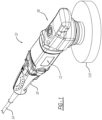
Fig. 1 is a perspective view of a rotating tool according to the disclosure. -
Fig. 2 is a side elevation view of the tool ofFig. 1 . -
Fig. 3 is a front elevation view ofFig. 1 . -
Fig. 4 is an exploded view of the adjustable stroke device. -
Fig. 5 is a cross-sectional view ofFig. 2 along line 5-5. -
Fig. 6 is a cross-sectional view ofFig. 3 along line 6-6. -
Fig. 7 is a cross-sectional view ofFig. 3 along line 7-7. -
Fig. 8 is a cross-sectional view ofFig. 2 along line 8-8. -
Figs. 9A-C are cross-sectional views likeFig. 8 with path tracks in phantom. - Example embodiments will now be described more fully with reference to the accompanying drawings.
- Turning to the figures, a tool is illustrated with an automated adjustable stroke device and is designated with the
reference numeral 10. The tool includes amotor 12, apower source 14 and switch 16 to activate and deactivate the power source. The power source is shown as a cord but could be rechargeable batteries. The motor includes apinion 18 positioned inside thehead housing 26 of the tool. Thedrivetrain head housing 26 includes a cavity to house adrivetrain 22. Thedrivetrain 22 includes a bevel gear meshing with thepinion 18. Thebevel gear 24 is coupled with the automatic adjustable stroke device 30 which is mounted, via housing 32, with the bottom of thehead housing 26. - The adjustable stroke device 30 includes a
counterbalance assembly mechanism 34, aworkpiece mounting assembly 36 and astroke adjustment mechanism 40. Ahousing 42 covers thecounterbalance assembly 34,workpiece mounting assembly 36 andstroke adjustment mechanism 40. Thehousing 42 defines a cavity that houses the elements. - The
counterbalance assembly 34 includes acounterbalance weight 44 secured with ashaft 46. Theshaft 46, has thebevel gear 24 secured at one end. The other end of theshaft 46 is secured with thecounterweight 44. Theshaft 46 includes akey recess 48 that receives key 50 to retain thebevel gear 24 on theshaft 46. - The
counterweight 44 has an overall infinity shape with a pair ofbores bore 52 receives abearing 56 of thestroke adjustment mechanism 40. Theweb 58, between thebores portion 60 of theshaft 46. Aweight portion 62, withbore 54, includesbores 64 on theweight portion 62 to receive fasteners to coupleplate 66 with theweight portion 62 of thecounterweight 44. Theplate 66 is circular shaped including abore 68 to receive thestroke adjustment mechanism 40. - The
stroke adjustment mechanism 40 includes ahollow gear wheel 70 includingteeth 72. Thegear wheel 70 includes ashaft portion 74 projecting from the top of thegear wheel 70. Theshaft portion 74 is received by the bearing 56 which is seated in thebore 52 of thecounterweight portion 44. Acircular base 76 is positioned into the bore of theplate 66. Thebase 76 includes anelliptical portion 78 that fits into anelliptical cutout 80 in the open end of thegear wheel 70. Thus, thebase 76 is secured to thegear wheel 70 against independent rotation. Also, bores 82 extend thru the base to secure the base 76 with theplate 66. Thegear wheel 70 includes abore 84 that receivesbearings 86 of theworkpiece mounting assembly 36. - The
workpiece mounting assembly 36 includes ashaft portion 88. The shaft portion includes ashaft 90 that projects into thebearings 86. Also, aworkpiece securement portion 92 projects below thebase 76 of thegear wheel 70. - The
housing 42 includes a pair ofportions housing portion 96 includes abore 100 that receives abearing 102 that receives theshaft 46 of thecounterbalance assembly 34. Thehousing portion 96 is secured withhousing portion 98. Thehousing portion 98 is ring shaped and defines acavity 104. The ring shapedhousing portion 98 includes aring gear 106 inside thecavity 104 on the inner wall of thehousing portion 98. Thehousing portion 98, at its one end, includes agroove 108 that receives theplate 66 of thecounterweight assembly 34. Theplate 66 rotates within thegroove 108 of thehousing portion 98. - In operation, the
motor 12 is activated to rotate thepinion 18. Thepinion 18 rotates thebevel gear 24. In turn, thebevel gear 24, keyed toshaft 46, rotates thecounterbalance assembly 34. As thecounterbalance assembly 34 is rotated, theplate 66 is rotated in thehousing portion 98. Thestroke adjustment mechanism 40 has itsshaft 74 positioned in counterweight bore 52, viabearings 56. Thus, as thecounterweight assembly 34 is rotated, thegear wheel 70 is rotated by thering gear 106 as thegear wheel 70 rotates and moves around the cavity. Theplate 66 is secured to thegear wheel 70 which, in turn, positions theworkpiece mounting assembly 36 that is positioned within thegear wheel 70. - Thus, as the
gear wheel 70 rotates, theshaft 90 of the workpiece mounting assembly also rotates within thebearings 86. Theworkpiece mounting assembly 36 rotates at a different rotational speed with respect to thegear wheel 70 usually at a slower speed of rotation compared to the rotation speed of thegear wheel 70. Thus, as thecounterbalance assembly 34 is rotated, thegearwheel 70 is rotated within thecavity 104 of thehousing part 98 along thegear ring 106. As this occurs, theworkpiece mounting assembly 36 is rotated within thegear wheel 70. In turn, theworkpiece 110 attached to theworkpiece mounting assembly 36 is automatically adjusted as it rotates throughout its path. Thus, the stroke is adjusted upon rotation of the counterweight shaft and the workpiece mounting assembly. This variably adjust a stroke radius of the workpiece attachment mechanism with respect to the central axis of the housing, defined by thecounterweight shaft 46. Thus, the stroke adjuster acts as a drivetrain automatically adjusting the mounting assembly stroke along the path illustrated inFig. 9A . - Since the
workpiece mounting assembly 36 rotates slower than thegear wheel 70, the axis of theshaft 90 remain in a line along thering gear 106 as illustrated in the path lines inFig. 9A . Thus, a dwell occurs so that theworkpiece mounting assembly 36 follows a somewhat linear, flattened arc, path along thering gear 106 before moving to the other side ofplate 66. This is different from current rotatable machines where the workpiece mounting assemblies reach the edge of the path and returns in a tight radius to the other side of the machine. This causes a pigtail or swirl in the finish that requires a substantial amount of work for the user to eliminate compared to the linear effect of the disclosure. - The foregoing description of the embodiments has been provided for purposes of illustration and description. It is not intended to be exhaustive or to limit the disclosure. Individual elements or features of a particular embodiment are generally not limited to that particular embodiment, but, where applicable, are interchangeable and can be used in a selected embodiment, even if not specifically shown or described. The same may also be varied in many ways. Such variations are not to be regarded as a departure from the disclosure, and all such modifications are intended to be included within the scope of the disclosure.
Claims (17)
- An automatic adjustable stroke device for a random orbital machine comprising:a housing having a central axis and a wall defining a cavity;a counterbalance shaft assembly rotatably disposed at least partially within the cavity and a shaft portion of the counterweight shaft assembly aligned with the central axis;a mounting assembly disposed at least partially within the cavity, the mounting assembly including a workpiece attachment mechanism; anda stroke adjuster coupling the counterweight shaft with the mounting assembly, the stroke adjuster enabling the mounting assembly to adjust its stroke upon rotation of counterweight shaft and the mounting assembly variably adjusts a stroke radius of the workpiece attachment mechanism with respect to the central axis of the housing, the stroke adjuster including a gear automatically adjusting the mounting assembly stroke.
- The automatic adjustable stroke device of Claim 1, wherein the counterbalance shaft assembly includes a counterweight portion.
- The automatic adjustable stroke device of Claim 2, wherein the counterweight portion is coupled with a base plate, the base plate rotatable with respect to the housing.
- The automatic adjustable stroke device of Claim 1, wherein the counterbalancing shaft assembly includes a bore for receiving the stroke adjuster.
- The automatic adjustable stroke device of Claim 1, wherein the stroke adjuster includes a bore for receiving the mounting assembly.
- The automatic adjustable stroke device of Claim 3, wherein the mounting assembly extends through the base plate to couple the workpiece attachment mechanism.
- The automatic adjustable stroke device of Claim 1, wherein the housing includes a ring gear meshing with the gear of the stroke adjuster.
- A rotating tool comprising:a housing and a motor, the motor including a drivetrain;a housing having a central axis and a wall defining a cavity;a counterbalance shaft assembly rotatably disposed at least partially within the cavity and a shaft portion of the counterweight shaft assembly aligned with the central axis;a mounting assembly disposed at least partially within the cavity, the mounting assembly including a workpiece attachment mechanism; anda stroke adjuster coupling the counterweight shaft with the mounting assembly, the stroke adjuster enabling the mounting assembly to adjust its stroke upon rotation of counterweight shaft and the mounting assembly variably adjusts a stroke radius of the workpiece attachment mechanism with respect to the central axis of the housing, the stroke adjuster including a gear automatically adjusting the mounting assembly stroke.
- The rotating tool of Claim 8, wherein the counterweight shaft assembly includes a counterbalance portion.
- The rotating tool of Claim 9, wherein the counterweight portion is coupled with a base plate, the base plate rotatable with respect to the housing.
- The rotating tool of Claim 8, wherein the counterbalance shaft assembly includes a bore for receiving the stroke adjuster.
- The rotating tool of Claim 8, wherein the stroke adjuster includes a bore for receiving the mounting assembly.
- The rotating tool of Claim 10, wherein the mounting assembly extends through the base plate to couple the workpiece attachment mechanism.
- The rotating tool of Claim 8, wherein the housing includes a ring gear meshing with the gear of the stroke adjuster.
- An automatic adjustable stroke device for a random orbital machine comprising:a housing having a central axis and a wall defining a cavity;a counterbalance shaft assembly rotatably disposed at least partially within the cavity and a shaft portion of the counterweight shaft assembly aligned with the central axis;a mounting assembly disposed at least partially within the cavity, the mounting assembly including a workpiece attachment mechanism; anda stroke adjuster coupling the counterweight shaft with the mounting assembly, the stroke adjuster enabling the mounting assembly to adjust its stroke upon rotation of counterweight shaft and the mounting assembly adjusts a stroke radius of the workpiece attachment mechanism with respect to the central axis of the housing so that the workpiece attachment mechanism dwells to provide a substantially linear travel path portion of the workpiece attachment mechanism during rotation of the shaft.
- The automatic adjustable stroke device of Claim 18, wherein the stroke adjuster includes a bore for receiving the mounting assembly.
- The automatic adjustable stroke device of Claim 16, wherein the mounting assembly rotates at a slower speed than the stroke adjuster.
Applications Claiming Priority (1)
| Application Number | Priority Date | Filing Date | Title |
|---|---|---|---|
| US17/687,010 US11878391B2 (en) | 2022-03-04 | 2022-03-04 | Adjustable stroke device |
Publications (1)
| Publication Number | Publication Date |
|---|---|
| EP4238697A1 true EP4238697A1 (en) | 2023-09-06 |
Family
ID=85381114
Family Applications (1)
| Application Number | Title | Priority Date | Filing Date |
|---|---|---|---|
| EP23158102.6A Pending EP4238697A1 (en) | 2022-03-04 | 2023-02-23 | Adjustable stroke device |
Country Status (6)
| Country | Link |
|---|---|
| US (2) | US11878391B2 (en) |
| EP (1) | EP4238697A1 (en) |
| JP (1) | JP2023129310A (en) |
| KR (1) | KR20230131154A (en) |
| CN (1) | CN116690368A (en) |
| CA (1) | CA3191042A1 (en) |
Citations (5)
| Publication number | Priority date | Publication date | Assignee | Title |
|---|---|---|---|---|
| EP0272725A2 (en) * | 1986-12-22 | 1988-06-29 | Guido Valentini | Portable electric tool with balanced orbital movement |
| EP0573916A1 (en) * | 1992-06-08 | 1993-12-15 | Makita Corporation | Sander |
| DE102004055271A1 (en) * | 2004-11-17 | 2006-05-18 | Robert Bosch Gmbh | eccentric |
| CN206356999U (en) * | 2016-12-28 | 2017-07-28 | 沪东重机有限公司 | Milling tool for combustion gas control block inverted cone bottom of chamber sealing surface |
| EP3693132A1 (en) * | 2019-02-08 | 2020-08-12 | Guido Valentini | Hand-held and hand-guided random orbital polishing or sanding power tool |
Family Cites Families (33)
| Publication number | Priority date | Publication date | Assignee | Title |
|---|---|---|---|---|
| US169753A (en) | 1875-11-09 | Improvement in dental polishing-tools | ||
| CA977583A (en) | 1972-09-13 | 1975-11-11 | Graham C. Grant | Stroke varying mechanism |
| US4328718A (en) | 1980-08-26 | 1982-05-11 | Emerson Electric Co. | Variable oscillator drive mechanism |
| GB8407058D0 (en) | 1984-03-19 | 1984-04-26 | Black & Decker Inc | Attachments for power tools |
| US5020281A (en) | 1989-04-03 | 1991-06-04 | American Pneumatic Technologies, Inc. | High speed rotary hand tool with adjustable head coupling |
| US5134777A (en) | 1991-12-05 | 1992-08-04 | Skil Corporation | Adjustable stroke reciprocating mechanism for a power tool |
| DK172770B1 (en) | 1996-04-17 | 1999-07-12 | Tiromat Kromer & Grebe Gmbh & | Flow packing type packaging machine with tool jaw adjustment |
| DE19629989C2 (en) | 1996-07-25 | 1999-01-28 | Metabowerke Kg | Grinder with a tool driven by a drive motor with an eccentric stroke |
| AU4569697A (en) | 1997-10-28 | 1999-05-17 | Romolo Bertani | Device for supporting a mandrel with angular transmission |
| US5879228A (en) | 1997-11-14 | 1999-03-09 | Sun; Yung-Yung | Pneumatic grinding/polishing machine |
| ES2193316T3 (en) | 1997-11-24 | 2003-11-01 | Grob Ernst Fa | PROCEDURE AND DEVICE FOR COLD TRAINING OF HOLLOW PARTS. |
| US6009767A (en) | 1998-04-23 | 2000-01-04 | Rudolph; Gary | Same-RPM rotary motion to eccentric rotary motion conversion |
| US5947804A (en) | 1998-04-27 | 1999-09-07 | Ryobi North America, Inc. | Adjustable eccentricity orbital tool |
| US6062960A (en) | 1998-04-27 | 2000-05-16 | Ryobi North America, Inc. | Orbital tool |
| US6206771B1 (en) | 1999-01-25 | 2001-03-27 | Dynabrade, Inc. | Balancer for orbital abrading machine |
| EP1227759B1 (en) | 1999-10-14 | 2004-01-02 | Karl Storz GmbH & Co. | Rotation joint for medical instruments |
| JP2001179591A (en) | 1999-12-24 | 2001-07-03 | Hitachi Koki Co Ltd | Orbital sander |
| US7658012B2 (en) | 2002-12-23 | 2010-02-09 | Milwaukee Electric Tool Corporation | Drive mechanism and power tool |
| US7022002B2 (en) | 2004-03-03 | 2006-04-04 | Dynabrade, Inc. | Modular counterweight apparatus for an orbital abrading machine |
| EP1740347B1 (en) | 2004-04-13 | 2009-06-17 | BLACK & DECKER INC. | Low profile electric sander |
| US7241209B2 (en) | 2004-08-13 | 2007-07-10 | General Electric Company | Orbiting polishing tool |
| US7721861B2 (en) | 2005-02-04 | 2010-05-25 | Positec Power Tools (Suzhou) Co., Ltd. | Clutch mechanism for use in power tools |
| CN100453271C (en) | 2005-02-04 | 2009-01-21 | 苏州宝时得电动工具有限公司 | Eccentricity regulating mechanism |
| FI126233B (en) | 2006-02-23 | 2016-08-31 | Oy Kwh Mirka Ab | Vibrating grinder |
| US7713110B2 (en) | 2006-09-05 | 2010-05-11 | Dynabrade, Inc. | Locking random orbital dual-action head assembly |
| US7238095B1 (en) | 2006-11-20 | 2007-07-03 | Storm Pneumtic Tool Co., Ltd. | Pneumatic grinder with improved muffling structure |
| DE102007062560A1 (en) | 2007-12-22 | 2009-06-25 | J. Wagner Gmbh | surface grinding machine |
| EP2127808A1 (en) | 2008-05-29 | 2009-12-02 | Black & Decker, Inc. | Power tool |
| US8740669B2 (en) | 2011-07-28 | 2014-06-03 | Omni Cubed, Inc. | Damage prevention tool and method |
| US10518384B2 (en) | 2015-11-02 | 2019-12-31 | Lake Country Tool, Llc | Adjustable stroke mechanism for random orbital machine |
| US10144106B2 (en) * | 2015-11-02 | 2018-12-04 | Lake Country Manufacturing, Inc. | Adjustable stroke mechanism for random orbital machine |
| US11493115B2 (en) | 2017-10-30 | 2022-11-08 | Lake Country Tool, Llc | Adjustable stroke device with cam |
| US11592055B2 (en) | 2018-08-30 | 2023-02-28 | Lake Country Tool, Llc | Adjustable stroke device with cam |
-
2022
- 2022-03-04 US US17/687,010 patent/US11878391B2/en active Active
-
2023
- 2023-02-22 JP JP2023025939A patent/JP2023129310A/en active Pending
- 2023-02-23 EP EP23158102.6A patent/EP4238697A1/en active Pending
- 2023-02-24 CA CA3191042A patent/CA3191042A1/en active Pending
- 2023-03-03 CN CN202310196882.2A patent/CN116690368A/en active Pending
- 2023-03-06 KR KR1020230029028A patent/KR20230131154A/en unknown
- 2023-12-08 US US18/533,679 patent/US20240100649A1/en active Pending
Patent Citations (5)
| Publication number | Priority date | Publication date | Assignee | Title |
|---|---|---|---|---|
| EP0272725A2 (en) * | 1986-12-22 | 1988-06-29 | Guido Valentini | Portable electric tool with balanced orbital movement |
| EP0573916A1 (en) * | 1992-06-08 | 1993-12-15 | Makita Corporation | Sander |
| DE102004055271A1 (en) * | 2004-11-17 | 2006-05-18 | Robert Bosch Gmbh | eccentric |
| CN206356999U (en) * | 2016-12-28 | 2017-07-28 | 沪东重机有限公司 | Milling tool for combustion gas control block inverted cone bottom of chamber sealing surface |
| EP3693132A1 (en) * | 2019-02-08 | 2020-08-12 | Guido Valentini | Hand-held and hand-guided random orbital polishing or sanding power tool |
Also Published As
| Publication number | Publication date |
|---|---|
| CN116690368A (en) | 2023-09-05 |
| US11878391B2 (en) | 2024-01-23 |
| US20240100649A1 (en) | 2024-03-28 |
| US20230278161A1 (en) | 2023-09-07 |
| KR20230131154A (en) | 2023-09-12 |
| CA3191042A1 (en) | 2023-09-04 |
| JP2023129310A (en) | 2023-09-14 |
Similar Documents
| Publication | Publication Date | Title |
|---|---|---|
| US11674571B2 (en) | Adjustable stroke device with cam | |
| US6306024B1 (en) | Orbital tool | |
| US11592055B2 (en) | Adjustable stroke device with cam | |
| US4586292A (en) | Machine imparting complex rotary motion for lapping a spherical inner diameter | |
| EP3326752B1 (en) | Adjustable stroke mechanism for random orbital machine | |
| US6062960A (en) | Orbital tool | |
| EP4238697A1 (en) | Adjustable stroke device | |
| EP4088862A1 (en) | Adjustable stroke device with cam | |
| BR102023004068A2 (en) | AUTOMATIC ADJUSTABLE STROKE DEVICES AND ROTARY TOOLS | |
| KR102445917B1 (en) | Grinding apparatus for shaft | |
| RU2776473C2 (en) | Stroke adjustment device | |
| KR200233756Y1 (en) | A grinding attachment having buff wheel | |
| KR20000060989A (en) | A grinding attachment having buff wheel | |
| JPH0560765U (en) | Grinder |
Legal Events
| Date | Code | Title | Description |
|---|---|---|---|
| PUAI | Public reference made under article 153(3) epc to a published international application that has entered the european phase |
Free format text: ORIGINAL CODE: 0009012 |
|
| STAA | Information on the status of an ep patent application or granted ep patent |
Free format text: STATUS: THE APPLICATION HAS BEEN PUBLISHED |
|
| AK | Designated contracting states |
Kind code of ref document: A1 Designated state(s): AL AT BE BG CH CY CZ DE DK EE ES FI FR GB GR HR HU IE IS IT LI LT LU LV MC ME MK MT NL NO PL PT RO RS SE SI SK SM TR |
|
| STAA | Information on the status of an ep patent application or granted ep patent |
Free format text: STATUS: REQUEST FOR EXAMINATION WAS MADE |
|
| 17P | Request for examination filed |
Effective date: 20240227 |
|
| RBV | Designated contracting states (corrected) |
Designated state(s): AL AT BE BG CH CY CZ DE DK EE ES FI FR GB GR HR HU IE IS IT LI LT LU LV MC ME MK MT NL NO PL PT RO RS SE SI SK SM TR |