EP4238653A1 - Classifier, power plant, and method for operating classifier - Google Patents
Classifier, power plant, and method for operating classifier Download PDFInfo
- Publication number
- EP4238653A1 EP4238653A1 EP22779681.0A EP22779681A EP4238653A1 EP 4238653 A1 EP4238653 A1 EP 4238653A1 EP 22779681 A EP22779681 A EP 22779681A EP 4238653 A1 EP4238653 A1 EP 4238653A1
- Authority
- EP
- European Patent Office
- Prior art keywords
- blade
- fuel
- radial direction
- particle size
- particles
- Prior art date
- Legal status (The legal status is an assumption and is not a legal conclusion. Google has not performed a legal analysis and makes no representation as to the accuracy of the status listed.)
- Pending
Links
- 238000000034 method Methods 0.000 title claims description 16
- 239000002245 particle Substances 0.000 claims abstract description 174
- 239000004449 solid propellant Substances 0.000 claims abstract description 55
- 239000012159 carrier gas Substances 0.000 claims description 20
- 238000010248 power generation Methods 0.000 claims description 4
- 239000000446 fuel Substances 0.000 abstract description 264
- 239000000843 powder Substances 0.000 abstract description 38
- 239000007789 gas Substances 0.000 description 41
- 239000003245 coal Substances 0.000 description 22
- 238000009826 distribution Methods 0.000 description 16
- 230000004048 modification Effects 0.000 description 13
- 238000012986 modification Methods 0.000 description 13
- MWUXSHHQAYIFBG-UHFFFAOYSA-N nitrogen oxide Inorganic materials O=[N] MWUXSHHQAYIFBG-UHFFFAOYSA-N 0.000 description 12
- 239000002028 Biomass Substances 0.000 description 11
- 230000007423 decrease Effects 0.000 description 11
- 238000010586 diagram Methods 0.000 description 11
- 239000000567 combustion gas Substances 0.000 description 10
- 230000012447 hatching Effects 0.000 description 10
- 239000000463 material Substances 0.000 description 10
- 230000000052 comparative effect Effects 0.000 description 9
- 230000032258 transport Effects 0.000 description 8
- 230000000694 effects Effects 0.000 description 7
- 238000007664 blowing Methods 0.000 description 6
- 238000002485 combustion reaction Methods 0.000 description 6
- 238000012545 processing Methods 0.000 description 6
- 230000008859 change Effects 0.000 description 5
- 238000003860 storage Methods 0.000 description 5
- QGZKDVFQNNGYKY-UHFFFAOYSA-N Ammonia Chemical compound N QGZKDVFQNNGYKY-UHFFFAOYSA-N 0.000 description 4
- CURLTUGMZLYLDI-UHFFFAOYSA-N Carbon dioxide Chemical compound O=C=O CURLTUGMZLYLDI-UHFFFAOYSA-N 0.000 description 4
- 230000001133 acceleration Effects 0.000 description 4
- 239000003638 chemical reducing agent Substances 0.000 description 4
- 230000000875 corresponding effect Effects 0.000 description 4
- 238000003825 pressing Methods 0.000 description 4
- 238000005452 bending Methods 0.000 description 3
- 238000001514 detection method Methods 0.000 description 3
- 230000002093 peripheral effect Effects 0.000 description 3
- 239000002699 waste material Substances 0.000 description 3
- OKTJSMMVPCPJKN-UHFFFAOYSA-N Carbon Chemical compound [C] OKTJSMMVPCPJKN-UHFFFAOYSA-N 0.000 description 2
- 230000009471 action Effects 0.000 description 2
- 229910021529 ammonia Inorganic materials 0.000 description 2
- 238000004364 calculation method Methods 0.000 description 2
- 229910052799 carbon Inorganic materials 0.000 description 2
- 229910002092 carbon dioxide Inorganic materials 0.000 description 2
- 239000001569 carbon dioxide Substances 0.000 description 2
- 230000002596 correlated effect Effects 0.000 description 2
- 238000001035 drying Methods 0.000 description 2
- 230000007613 environmental effect Effects 0.000 description 2
- 230000006870 function Effects 0.000 description 2
- 238000010030 laminating Methods 0.000 description 2
- 239000000314 lubricant Substances 0.000 description 2
- 239000002006 petroleum coke Substances 0.000 description 2
- 230000009467 reduction Effects 0.000 description 2
- 230000001846 repelling effect Effects 0.000 description 2
- 238000007493 shaping process Methods 0.000 description 2
- 239000007787 solid Substances 0.000 description 2
- 239000002023 wood Substances 0.000 description 2
- 244000025254 Cannabis sativa Species 0.000 description 1
- 230000001154 acute effect Effects 0.000 description 1
- QVGXLLKOCUKJST-UHFFFAOYSA-N atomic oxygen Chemical compound [O] QVGXLLKOCUKJST-UHFFFAOYSA-N 0.000 description 1
- 230000015572 biosynthetic process Effects 0.000 description 1
- 239000003054 catalyst Substances 0.000 description 1
- 230000003197 catalytic effect Effects 0.000 description 1
- 238000006243 chemical reaction Methods 0.000 description 1
- 238000004891 communication Methods 0.000 description 1
- 238000005520 cutting process Methods 0.000 description 1
- 239000000428 dust Substances 0.000 description 1
- 239000012530 fluid Substances 0.000 description 1
- 238000010438 heat treatment Methods 0.000 description 1
- 230000006872 improvement Effects 0.000 description 1
- 230000010365 information processing Effects 0.000 description 1
- 238000012886 linear function Methods 0.000 description 1
- 238000012423 maintenance Methods 0.000 description 1
- 238000004519 manufacturing process Methods 0.000 description 1
- 238000002156 mixing Methods 0.000 description 1
- 239000000203 mixture Substances 0.000 description 1
- 239000001301 oxygen Substances 0.000 description 1
- 229910052760 oxygen Inorganic materials 0.000 description 1
- 239000008188 pellet Substances 0.000 description 1
- 238000005504 petroleum refining Methods 0.000 description 1
- 230000008569 process Effects 0.000 description 1
- 238000003672 processing method Methods 0.000 description 1
- 230000001737 promoting effect Effects 0.000 description 1
- 238000012887 quadratic function Methods 0.000 description 1
- 239000002994 raw material Substances 0.000 description 1
- 238000007789 sealing Methods 0.000 description 1
- 239000004065 semiconductor Substances 0.000 description 1
- 239000010802 sludge Substances 0.000 description 1
- 238000011144 upstream manufacturing Methods 0.000 description 1
- WTHDKMILWLGDKL-UHFFFAOYSA-N urea;hydrate Chemical compound O.NC(N)=O WTHDKMILWLGDKL-UHFFFAOYSA-N 0.000 description 1
- 238000010792 warming Methods 0.000 description 1
- XLYOFNOQVPJJNP-UHFFFAOYSA-N water Substances O XLYOFNOQVPJJNP-UHFFFAOYSA-N 0.000 description 1
- 238000003466 welding Methods 0.000 description 1
Images







Classifications
-
- F—MECHANICAL ENGINEERING; LIGHTING; HEATING; WEAPONS; BLASTING
- F23—COMBUSTION APPARATUS; COMBUSTION PROCESSES
- F23G—CREMATION FURNACES; CONSUMING WASTE PRODUCTS BY COMBUSTION
- F23G5/00—Incineration of waste; Incinerator constructions; Details, accessories or control therefor
- F23G5/02—Incineration of waste; Incinerator constructions; Details, accessories or control therefor with pretreatment
- F23G5/033—Incineration of waste; Incinerator constructions; Details, accessories or control therefor with pretreatment comminuting or crushing
-
- B—PERFORMING OPERATIONS; TRANSPORTING
- B02—CRUSHING, PULVERISING, OR DISINTEGRATING; PREPARATORY TREATMENT OF GRAIN FOR MILLING
- B02C—CRUSHING, PULVERISING, OR DISINTEGRATING IN GENERAL; MILLING GRAIN
- B02C23/00—Auxiliary methods or auxiliary devices or accessories specially adapted for crushing or disintegrating not provided for in preceding groups or not specially adapted to apparatus covered by a single preceding group
- B02C23/08—Separating or sorting of material, associated with crushing or disintegrating
- B02C23/10—Separating or sorting of material, associated with crushing or disintegrating with separator arranged in discharge path of crushing or disintegrating zone
- B02C23/12—Separating or sorting of material, associated with crushing or disintegrating with separator arranged in discharge path of crushing or disintegrating zone with return of oversize material to crushing or disintegrating zone
-
- B—PERFORMING OPERATIONS; TRANSPORTING
- B07—SEPARATING SOLIDS FROM SOLIDS; SORTING
- B07B—SEPARATING SOLIDS FROM SOLIDS BY SIEVING, SCREENING, SIFTING OR BY USING GAS CURRENTS; SEPARATING BY OTHER DRY METHODS APPLICABLE TO BULK MATERIAL, e.g. LOOSE ARTICLES FIT TO BE HANDLED LIKE BULK MATERIAL
- B07B7/00—Selective separation of solid materials carried by, or dispersed in, gas currents
- B07B7/08—Selective separation of solid materials carried by, or dispersed in, gas currents using centrifugal force
- B07B7/083—Selective separation of solid materials carried by, or dispersed in, gas currents using centrifugal force generated by rotating vanes, discs, drums, or brushes
-
- B—PERFORMING OPERATIONS; TRANSPORTING
- B02—CRUSHING, PULVERISING, OR DISINTEGRATING; PREPARATORY TREATMENT OF GRAIN FOR MILLING
- B02C—CRUSHING, PULVERISING, OR DISINTEGRATING IN GENERAL; MILLING GRAIN
- B02C15/00—Disintegrating by milling members in the form of rollers or balls co-operating with rings or discs
- B02C2015/002—Disintegrating by milling members in the form of rollers or balls co-operating with rings or discs combined with a classifier
-
- F—MECHANICAL ENGINEERING; LIGHTING; HEATING; WEAPONS; BLASTING
- F23—COMBUSTION APPARATUS; COMBUSTION PROCESSES
- F23G—CREMATION FURNACES; CONSUMING WASTE PRODUCTS BY COMBUSTION
- F23G2201/00—Pretreatment
- F23G2201/60—Separating
- F23G2201/602—Separating different sizes
Definitions
- the present disclosure related to a classifier, a power plant, and a method for operating a classifier.
- solid fuel such as coal or biomass fuel is crushed by a pulverizer (mill) into fine powder within a predetermined particle size range and supplied to a combustion device.
- the solid fuel such as coal or biomass fuel put into a crushing table is sandwiched and crushed between the crushing table and a crushing roller, and the pulverized fuel within a predetermined particle size range (fineness), of the solid fuel crushed into fine powder (hereinafter, the crushed solid fuel is referred to as "crushed fuel”)
- a carrier gas primary air
- steam is generated by heat exchange with a combustion gas produced by burning pulverized fuel in a boiler, and a steam turbine is rotationally driven by the steam to rotationally drive a generator connected to the steam turbine, whereby electric power generation is performed.
- a rotary classifier As one of the classifiers that are provided in the mill, for example, a rotary classifier is known.
- the rotary classifier has a plurality of blades that are disposed at equal intervals in the circumferential direction around a rotational axis.
- the rotary classifier is a device that performs classification by causing coarse powder fuel (crushed fuel larger than a predetermined particle size), which is large in weight and on which a centrifugal force acts greatly, to repel to the outer periphery side of the blade, and causing pulverized fuel (crushed fuel smaller than a predetermined particle size), which is small in weight and on which a transport force due to an air flow of primary air acts greatly, to pass to the inner periphery side of the blade, when the crushed fuel passes between the plurality of blades that rotate around the rotational axis.
- the rotary classifier has a main body portion that rotates around the rotational axis.
- the main body portion holds the upper and lower sides of the blade, so that the blade can revolve around the rotational axis.
- the main body portion is held by bearings and rotated at a predetermined rotation speed by a power source such as a motor. By changing the rotation speed, the force acting on the crushed fuel can be adjusted to obtain a predetermined fineness (classification performance).
- the blade of the rotary classifier has a flat plate shape.
- classification performance the performance of repelling coarse powder fuel to the outer periphery side of the blade and passing pulverized fuel between the blades
- PTL 1 a simple flat plate shape
- PTL 1 there is described a rotary classifier in which an angle with a direction of a rotation radius is large at an upstream end (an inlet end) of each of a plurality of classifying blades rotating around a vertical axis and the angle is small at a downstream end (an outlet end). That is, in PTL 1, there is described a rotary classifier in which a classifying blade is bent.
- the classifying blade (blade) described in PTL 1 has a shape that is bent such that an inlet side portion (an outer portion in the radial direction) and an outlet side portion (an inner portion in the radial direction) have different angles (angles with respect to the radial direction).
- a particle size range of the crushed fuel that can be repelled toward the outer periphery side changes according to the angle of the blade. Therefore, in the blade described in PTL 1, there is a case where crushed fuel having a particle size of an intermediate degree, which is repelled to the outer periphery side at the inlet side portion of the blade but cannot be repelled to the outer periphery side at the outlet side portion, collides with the blade. In this case, the result of classification is greatly different between a case of colliding with the outlet side portion and a case of colliding with the inlet side portion.
- Whether to collide with the inlet side portion of the blade or to collide with the outlet side portion is determined by an intrusion position of the crushed fuel into the rotary classifier. Specifically, in a case of intruding into the rotary classifier from a distant place in the radial direction of the blade, the crushed fuel collides with the outlet side portion, and in a case of intruding into the rotary classifier from a near place in the radial direction of the blade, the crushed fuel collides with the inlet side portion.
- the present disclosure has been made in view of such circumstances, and has an object to provide a classifier, a power plant, and a method for operating a classifier, in which it is possible to improve classification performance.
- a classifier, a power plant, and a method for operating a classifier of the present disclosure adopt the following means.
- a classifier is a classifier that classifies particles introduced along with a carrier gas into particles larger than a predetermined particle size and particles equal to or smaller than the predetermined particle size, the classifier including: a plurality of blades that extend in an up-down direction and are disposed side by side in a circumferential direction on a virtual circle centered on a central axis extending in the up-down direction, and to which the particles are introduced along with the carrier gas heading from an outer side in a radial direction to an inner side, in which the blade has a collision surface with which the introduced particles collide, and which repels the particles larger than the predetermined particle size, among the collided particles, in an outward direction in the radial direction, and repels the particles equal to or smaller than the predetermined particle size in an inward direction in the radial direction, and in the collision surface, an angle formed by a tangent line to the virtual circle and a normal line to the collision surface is larger on an outer side in the radial direction than
- a method for operating a classifier is a method for operating a classifier that classifies particles introduced along with a carrier gas into particles larger than a predetermined particle size and particles equal to or smaller than the predetermined particle size, in which the classifier includes a plurality of blades that extend in an up-down direction and are disposed side by side in a circumferential direction on a virtual circle centered on a central axis extending in the up-down direction, and to which the particles are introduced along with the carrier gas heading from an outer side in a radial direction to an inner side, the blade has a collision surface with which the introduced particles collide, and which repels the particles larger than the predetermined particle size, among the collided particles, in an outward direction in the radial direction, and repels the particles equal to or smaller than the predetermined particle size in an inward direction in the radial direction, and in the collision surface, an angle formed by a tangent line to the virtual circle and a normal line to the collision surface is larger on an
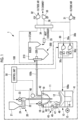
- a power plant 1 includes a solid fuel crushing device 100 and a boiler 200.
- upper indicates a vertically upper side
- upper in an upper portion, an upper surface, or the like indicates a portion on the vertically upper side
- lower indicates a portion on the vertically lower side
- a vertical direction is not exact and includes an error.
- the solid fuel crushing device 100 of the present embodiment is a device that crushes solid fuel (carbon-containing solid fuel) such as coal or biomass fuel, as an example, to generate pulverized fuel, and supplies the pulverized fuel to a burner (a combustion device) 220 of the boiler 200.
- solid fuel carbon-containing solid fuel
- a burner a combustion device
- the power plant 1 that includes the solid fuel crushing device 100 and the boiler 200 shown in Fig. 1 includes a single solid fuel crushing device 100
- a system may be adopted in which a plurality of solid fuel crushing devices 100 are provided respectively corresponding to a plurality of burners 220 of a single boiler 200.
- the solid fuel crushing device 100 of the present embodiment includes a mill(a pulverizer) 10, a coal feeder (a fuel feeder) 20, an air blowing part (a carrier gas supply part) 30, a state detecting part 40, and a control unit (determination unit) 50.
- the mill 10 that crushes solid fuel such as coal or biomass fuel to be supplied to the boiler 200 into pulverized fuel, which is finely powdered solid fuel, may be of a type of crushing only coal, a type of crushing only biomass fuel, or a type of crushing biomass fuel together with coal.
- the biomass fuel is a renewable organic resource derived from living organisms, and is, for example, thinned wood, waste wood, driftwood, grass, waste, sludge, tires, recycled fuel (pellets or chips) made using these as raw materials, or the like. However, it is not limited to those presented here. Since the biomass fuel takes in carbon dioxide during a growth process of biomass, it is considered to be carbon-neutral because it does not emit carbon dioxide that is a global warming gas.
- the mill 10 includes a housing 11, a crushing table (a rotary table) 12, a crushing roller 13, a drive unit 14, a mill motor 15 that is connected to the drive unit 14 and rotationally drives the crushing table 12, a rotary classifier 16, a fuel supply part 17, and a classifier motor 18 that rotationally drives the rotary classifier 16.
- the housing 11 is a casing that is formed in a tubular shape extending in the vertical direction and accommodates the crushing table 12, the crushing roller 13, the rotary classifier 16, and the fuel supply part 17.
- the fuel supply part 17 is mounted to a central portion of a ceiling portion 42 of the housing 11.
- the fuel supply part 17 is for supplying the solid fuel introduced from a bunker 21 into the housing 11, and is disposed along an up-down direction at a center position of the housing 11, and a lower end portion thereof extends to the inside of the housing 11.
- the drive unit 14 is installed in the vicinity of a bottom surface portion 41 of the housing 11, and the crushing table 12 that is rotated by a driving force that is transmitted from the mill motor 15 connected to the drive unit 14 is disposed to be rotatable.
- the crushing table 12 is a circular member when viewed in a plan view, and is disposed such that the lower end portion of the fuel supply part 17 faces it.
- the upper surface of the crushing table 12 may have, for example, an inclined shape in which a central portion is low and it becomes higher toward the outer side to form a shape in which an outer peripheral portion is bent upward.
- the fuel supply part 17 supplies solid fuel (in the present embodiment, for example, coal or biomass fuel) from above toward the crushing table 12 below, and the crushing table 12 crushes the supplied solid fuel between itself and the crushing roller 13.
- the solid fuel When the solid fuel is introduced from the fuel supply part 17 toward a substantially central region of the crushing table 12, the solid fuel is led toward the outer periphery side of the crushing table 12 by a centrifugal force due to the rotation of the crushing table 12, and is sandwiched and crushed between the crushing table 12 and the crushing roller 13.
- the crushed solid fuel is blown upward by a carrier gas (hereinafter referred to as primary air) introduced from a carrier gas flow path 100a (hereinafter referred to as a primary air flow path), and is led to the rotary classifier 16.
- a carrier gas hereinafter referred to as primary air
- carrier gas flow path 100a hereinafter referred to as a primary air flow path
- a discharge outlet (not shown) that allows the primary air flowing in from the primary air flow path 100a to flow out to a space above the crushing table 12 in the housing 11 is provided at the outer periphery of the crushing table 12.
- a swirl blade (not shown) is installed at the discharge outlet to impart a swirling force to the primary air blown out from the discharge outlet.
- the primary air with the swirling force applied thereto by the swirl blade becomes an air flow having a swirling velocity component, and transports the solid fuel crushed on the crushing table 12 to the rotary classifier 16 on the upper side in the housing 11.
- the solid fuel larger than a predetermined particle size, of the crushed solid fuel is classified by the rotary classifier 16, or falls to be returned to the crushing table 12 without reaching the rotary classifier 16 and crushed between the crushing table 12 and the crushing roller 13 again.
- the crushing roller 13 is a rotating body that crushes the solid fuel supplied from the fuel supply part 17 to the crushing table 12.
- the crushing roller 13 is pressed against the upper surface of the crushing table 12 and crushes the solid fuel in cooperation with the crushing table 12.
- a plurality of crushing rollers 13 are disposed at constant intervals in a circumferential direction so as to press the upper surface of the crushing table 12.
- three crushing rollers 13 are disposed at equal intervals in the circumferential direction at angular intervals of 120° on an outer peripheral portion.
- the portions (pressing portions) where the three crushing rollers 13 are in contact with the upper surface of the crushing table 12 are equidistant from a rotation center axis of the crushing table 12.
- the crushing roller 13 can be swung up and down by a journal head 45 and is supported to be movable toward and away from the upper surface of the crushing table 12.
- the crushing table 12 rotates in a state where an outer peripheral surface of the crushing roller 13 is in contact with the solid fuel on the upper surface of the crushing table 12, the crushing roller 13 receives a rotational force from the crushing table 12 and rotates together with the crushing table 12.
- the solid fuel is supplied from the fuel supply part 17, the solid fuel is pressed and crushed between the crushing roller 13 and the crushing table 12.
- a support arm 47 of the journal head 45 is supported by a support shaft 48 along a horizontal direction at its intermediate portion such that the crushing roller 13 can swing in the up-down direction with the support shaft 48 as a center at a side surface portion of the housing 11. Further, a pressing device 49 is provided at an upper end portion of the support arm 47 on the vertically upper side. The pressing device 49 is fixed to the housing 11 and applies a load to the crushing roller 13 through the support arm 47 or the like so as to press the crushing roller 13 against the crushing table 12.
- the drive unit 14 is a device that transmits a driving force to the crushing table 12 and rotates the crushing table 12 around the central axis thereof.
- the drive unit 14 is connected to the mill motor 15 and transmits the driving force of the mill motor 15 to the crushing table 12.
- the rotary classifier 16 is provided at an upper portion of the housing 11 and has a hollow and substantially inverted conical outer shape.
- the rotary classifier 16 has, at positions on an outer periphery thereof, a plurality of blades 60 extending in the up-down direction.
- the blades 60 are provided at predetermined intervals (equal intervals) around a central axis C of the rotary classifier 16.
- the rotary classifier 16 is a device that classifies the solid fuel (hereinafter, the crushed solid fuel is referred to as "crushed fuel") crushed by the crushing table 12 and the crushing roller 13 into fuel larger than a predetermined particle size (for example, a range of 70 to 100 um in coal) (hereinafter, the crushed fuel exceeding a predetermined particle size will be referred to as “coarse powder fuel”) and fuel equal to or smaller than the predetermined particle size (hereinafter, the crushed uel equal to or smaller than the predetermined particle size will be referred to as "pulverized fuel”).
- a predetermined particle size for example, a range of 70 to 100 um in coal
- the rotary classifier 16 which classifies the solid fuel by rotation, is also called a rotary separator, and is provided with a rotational driving force by the classifier motor 18 that is controlled by the control unit 50 to rotate around the fuel supply part 17 with a cylindrical shaft 71 (refer to Fig. 2 ) extending in the up-down direction of the housing 11 as a center. Details of the rotary classifier 16 will be described later.
- a fixed classifier having a fixed hollow inverted conical casing and a plurality of fixed swirl blades instead of the blades 60 at positions on an outer periphery of the casing may be used.
- the large-diameter coarse powder fuel of the crushed fuel that reaches the rotary classifier 16 is knocked down by the blade 60 due to the relative balance between a centrifugal force generated by the rotation of the blade 60 and a centripetal force caused by the primary air flow, and returned to the crushing table 12 to be crushed again, and the pulverized fuel is led to an outlet port 19 in the ceiling portion 42 of the housing 11.
- the pulverized fuel classified by the rotary classifier 16 is discharged together with the primary air from the outlet port 19 to a pulverized fuel supply flow path 100b and supplied to the burner 220 of the boiler 200.
- the pulverized fuel supply flow path 100b is also called a pulverized coal pipe in a case where the solid fuel is coal.
- the fuel supply part 17 is mounted such that the lower end portion thereof extends to the inside of the housing 11 along the up-down direction so as to penetrate the ceiling portion 42 of the housing 11, and supplies the solid fuel introduced from the upper portion of the fuel supply part 17 to the substantially central region of the crushing table 12.
- the fuel supply part 17 is supplied with the solid fuel from the coal feeder 20.
- the coal feeder 20 includes a transport part 22 and a coal feeder motor 23.
- the transport part 22 is, for example, a belt conveyor, and transports the solid fuel discharged from a lower end portion of a downspout 24 directly below the bunker 21 to the upper portion of the fuel supply part 17 of the mill 10 by a driving force from the coal feeder motor 23, and introduces the solid fuel into the fuel supply part 17.
- the primary air for transporting the pulverized fuel to the burner 220 is supplied to the inside of the mill 10, and the pressure of the primary air is higher than the pressure in the coal feeder 20 or the bunker 21.
- the amount of solid fuel that is supplied to the mill 10 is adjusted, for example, by the moving speed of the belt conveyor of the transport part 22.
- the air blowing part 30 is a device that blows the primary air for drying the crushed fuel and transporting it to the rotary classifier 16 to the inside of the housing 11.
- the air blowing part 30 includes a primary air fan (PAF) 31 and a hot gas flow path 30a, a cold gas flow path 30b, a hot gas damper 30c, and a cold gas damper 30d.
- PAF primary air fan
- the hot gas flow path 30a supplies part of the air (outside air) sent from the primary air fan 31 as a hot gas heated by passing through a heat exchanger 34 such as an air preheater, for example.
- the hot gas damper 30c is provided on the downstream side of the hot gas flow path 30a.
- the degree of opening of the hot gas damper 30c is controlled by the control unit 50.
- the flow rate of the hot gas that is supplied from the hot gas flow path 30a is determined by the degree of opening of the hot gas damper 30c.
- the cold gas flow path 30b supplies part of the air sent from the primary air fan 31 as a cold gas having room temperature.
- the cold gas damper 30d is provided on the downstream side of the cold gas flow path 30b.
- the degree of opening of the cold gas damper 30d is controlled by the control unit 50.
- the flow rate of the cold gas that is supplied from the cold gas flow path 30b is determined by the degree of opening of the cold gas damper 30d.
- the flow rate of the primary air is the sum of the flow rate of the hot gas that is supplied from the hot gas flow path 30a and the flow rate of the cold gas that is supplied from the cold gas flow path 30b, and the temperature of the primary air is determined by the mixing ratio or the like of the hot gas that is supplied from the hot gas flow path 30a and the cold gas that is supplied from the cold gas flow path 30b, and is controlled by the control unit 50.
- a portion of a combustion gas discharged from the boiler 200 through a gas recirculation fan may be led to the hot gas that is supplied from the hot gas flow path 30a to form a mixture, thereby adjusting oxygen concentration of the primary air that is blown to the inside of the housing 11 from the primary air flow path 100a.
- the state detecting part 40 of the mill 10 transmits measured or detected data to the control unit 50.
- the state detecting part 40 of the present embodiment is, for example, differential pressure measuring means, and measures the differential pressure between the pressure at a portion where the primary air flows from the primary air flow path 100a to the inside of the housing 11, and the pressure at the outlet port 19 where the primary air and the pulverized fuel are discharged from the inside of the housing 11 to the pulverized fuel supply flow path 100b, as differential pressure in the mill 10.
- the increase or decrease in the differential pressure in the mill 10 corresponds to the increase or decrease in the amount of crushed fuel circulating between the vicinity of the rotary classifier 16 inside the housing 11 and the vicinity of the crushing table 12 due to the classification effect of the rotary classifier 16.
- the amount of pulverized fuel that is discharged from the outlet port 19 can be adjusted with respect to the amount of solid fuel that is supplied to the mill 10 by adjusting the rotational frequency of the rotary classifier 16 according to the differential pressure in the mill 10, the amount of pulverized fuel corresponding to the amount of solid fuel supplied to the mill 10 can be stably supplied to the burner 220 provided in the boiler 200 within a range in which the particle size of the pulverized fuel does not affect the combustibility of the burner 220.
- the state detecting part 40 of the present embodiment is, for example, temperature measuring means, and detects the temperature of the primary air that is supplied to the inside of the housing 11 (the temperature of the primary air at a mill inlet) or the temperature of the primary air from the space above the crushing table 12 inside the housing 11 to the outlet port 19, and controls the air blowing part 30 so as not to exceed an upper limit temperature.
- the upper limit temperature is determined in consideration of the possibility of ignition of the solid fuel, or the like.
- the primary air is cooled by transporting the crushed fuel while drying it inside the housing 11, and the temperature of the primary air at the outlet port 19 is, for example, in a range of about 60 to 90 degrees.
- the control unit 50 is a device that controls each part of the solid fuel crushing device 100.
- the control unit 50 may transmit a drive instruction to, for example, the mill motor 15 to control the rotation speed of the crushing table 12.
- the control unit 50 can transmit a drive instruction to, for example, the classifier motor 18 to control the rotation speed of the rotary classifier 16, thereby adjusting the classification performance, and stably supply the pulverized fuel to the burner 220 by optimizing the differential pressure in the mill 10, that is, the amount of crushed fuel circulating inside the mill 10 within a predetermined range.
- the classification performance is performance necessary for classification, such as a classification characteristic, a passage characteristic, and classification accuracy, which will be described later.
- control unit 50 can transmits a drive instruction to, for example, the coal feeder motor 23 of the coal feeder 20 to adjust the amount of solid fuel (coal feed amount) that is supplied to the fuel supply part 17 by being transported by the transport part 22.
- control unit 50 can transmit an opening degree instruction to the air blowing part 30 to control the degrees of opening of the hot gas damper 30c and the cold gas damper 30d, thereby adjusting the flow rate and temperature of the primary air.
- control unit 50 controls the degrees of opening of the hot gas damper 30c and the cold gas damper 30d such that the flow rate of the primary air that is supplied to the inside of the housing 11 and the temperature of the primary air at the outlet port 19 become predetermined values set corresponding to the coal feed amount for each type of solid fuel.
- the control unit 50 is composed of, for example, a CPU (Central Processing Unit), a RAM (Random Access Memory), a ROM (Read Only Memory), a computer-readable storage medium, and the like. Then, a series of processing for realizing various functions is stored in a storage medium or the like in the form of a program, as an example, and the CPU reads out this program to a RAM or the like, and executes processing for information processing and calculation, whereby various functions are realized.
- a form installed in advance in a ROM or other storage medium a form of being provided in a state where it is stored in a computer-readable storage medium, a form of being delivered via wired or wireless communication means, or the like may be applied.
- the computer-readable storage media is a magnetic disk, a magneto-optical disk, a CD-ROMs, a DVD-ROMs, a semiconductor memory, or the like. Further, the HDD may be replaced with a solid state disk (SSD) or the like.
- SSD solid state disk
- the boiler 200 that perform combustion using the pulverized fuel that is supplied from the solid fuel crushing device 100 to generate steam will be described.
- the boiler 200 includes a furnace 210 and the burner 220.
- the burner 220 is a device that forms a flame by burning pulverized fuel by using primary air containing the pulverized fuel that is supplied from the pulverized fuel supply flow path 100b and secondary air that is supplied by heating air (outside air) sent from a forced draft fan (FDF) 32 in the heat exchanger 34.
- the combustion of the pulverized fuel is performed in the furnace 210, and a high-temperature combustion gas is discharged to the outside of the boiler 200 after passing through a heat exchanger (not shown) such as an evaporator, a superheater, or an economizer.
- the combustion gas flowing through the flue 36 is denitrated by a denitration device 35.
- the denitration device 35 is for supplying a reducing agent such as ammonia or urea water, which has an action to reduce nitrogen oxides, into the flow path through which the combustion gas flows, and removing or reducing the nitrogen oxides in the combustion gas by promoting the reaction between the nitrogen oxides in the combustion gas supplied with the reducing agent and the reducing agent by the catalytic action of a denitration catalyst installed in the denitration device 35.
- the denitrated combustion gas is subjected to heat exchange between the air sent from the primary air fan 31 and the air sent from the forced draft fan 32 in the heat exchanger 34 such as an air preheater, for example, is subjected to predetermined processing by an environmental device (an electric dust collector, a desulfurizer, or the like) (not shown) through an induced draft fan (IDF) 33, and is led to a chimney (not shown) to be discharged to the outside air.
- an environmental device an electric dust collector, a desulfurizer, or the like
- IDF induced draft fan
- Feed water to each heat exchanger of the boiler 200 is heated in an economizer (not shown), and then further heated by an evaporator (not shown) and a superheater (not shown) to generate high-temperature and high-pressure steam, and the steam is sent to a steam turbine (not shown), which is a power generation part, to rotationally drive the steam turbine, and to rotationally drive a generator (not shown) connected to the steam turbine to generate electric power, whereby the power plant 1 is configured.
- the "circumferential direction” and the “radial direction” mean a “circumferential direction” and a “radial direction” when the central axis C is the center.
- the rotary classifier 16 is provided at the upper portion of the housing 11, as shown in Fig. 1 .
- the rotary classifier 16 rotates around the central axis C extending in the up-down direction, as shown in Fig. 2 .
- the rotary classifier 16 rotates clockwise when viewed from a plan view, as shown by an arrow A1 in Figs. 2 and 3 .
- the rotation direction of the rotary classifier 16 is a direction opposite to the swirling direction of the primary air which is formed by the swirl blades installed at the discharge outlet.
- the rotary classifier 16 is provided with a rotational driving force by a motor (not shown).
- the rotational frequency of the motor is controlled by the control unit 50.
- the rotary classifier 16 has a main body portion 70 having a hollow and substantially inverted conical outer shape.
- An inner space S1 is formed inside the main body portion 70.
- the main body portion 70 has, in an integrated manner, the cylindrical shaft 71 covering the fuel supply part 17 and extending along the central axis C, an upper end portion 72 extending in the radial direction from the upper end of the cylindrical shaft 71, and a lower end portion 73 extending in the radial direction from the lower end of the cylindrical shaft 71.
- the upper end portion 72 defines the upper end of the inner space S1.
- the lower end portion 73 defines the lower end of the inner space S1.
- the rotary classifier 16 has a plurality of blades 60 provided at positions on the outer periphery of the main body portion 70. Each blade 60 extends in the up-down direction. Each blade 60 is a plate-shaped member. Each blade 60 is fixed to the upper end portion 72 at the upper end thereof. Further, each blade 60 is fixed to the lower end portion 73 at the lower end thereof. Each blade 60 is inclined such that the lower end side is closer to the central axis C than the upper end side is.
- the upper end portion 72 is formed with an opening 72a to which the outlet port 19 (refer to Fig. 1 ) is connected.
- the plurality of blades 60 are providedin parallel around the central axis C of the rotary classifier 16 at predetermined intervals (equal intervals). Specifically, the blades 60 are disposed side by side at predetermined intervals on a virtual circle V centered on the central axis C. Further, each blade 60 is disposed so as to be inclined at a predetermined angle with respect to the radial direction when viewed from in a plan view. Further, a gap is formed between the blades 60 adjacent to each other in the circumferential direction. The gap makes the inner space S1 with respect to the plurality of blades 60 and an outer space S2 with respect to the blades 60 communicate with each other. The crushed fuel is led to each blade 60 along with the primary air heading from the outer side in the radial direction to the inner side.
- Each blade 60 has a collision surface 61 that is a surface on the front side in the rotation direction, and a back surface 65 that is a surface on the rear side in the rotation direction.
- the crushed fuel that includes the pulverized fuel B2 and coarse powder fuel B1 collides with the collision surface 61.
- a radially outward force (a centrifugal force and a collision force, hereinafter referred to as an outward force) shown by an arrow A2 and a radially inward force (a centripetal force due to the flow of the primary air, hereinafter referred to as inward force) shown by an arrow A3 act on the crushed fuel that collides with the collision surface 61.
- a strong outward force A2 acts on the coarse powder fuel B1 that collides with the collision surface 61 due to the influence of a centrifugal force.
- the coarse powder fuel B1 is repelled to the outer side of the blade 60 (the outer space S2 side) as shown by an arrow A4 against the inward force A3.
- the centrifugal force acting on the pulverized fuel B2 that collides with the collision surface 61 is relatively weak. In this way, since the force acting on the pulverized fuel B2 is dominated by the inward force shown by the arrow A3, the pulverized fuel B2 is led to the inner side of the blade 60 (the inner space S1 side) as shown by an arrow A5.
- the rotary classifier 16 classifies the coarse powder fuel B1 and the pulverized fuel B2, based on this principle.
- each blade 60 will be described using the cross-sectional shape in the up-down direction (the cross-sectional shape when cut along a plane (a horizontal plane) orthogonal to the up-down direction).
- cross-sectional shape in a case where the term "cross-sectional shape” is simply used, it means a cross section (blade cross section) when the blade is cut along the horizontal plane.
- Each blade 60 has a uniform shape along the up-down direction. That is, each blade 60 has the same cross-sectional shape at any position in the up-down direction.
- each blade 60 has the collision surface 61 and the back surface 65 on the side opposite to the collision surface 61, as described above.
- the back surface 65 is a flat surface.
- the collision surface 61 has a curved surface 62 disposed on the outer side in the radial direction, and a flat surface 63 disposed on the inner side in the radial direction with respect to the curved surface 62.
- the curved surface 62 and the flat surface 63 are smoothly connected at a boundary point D.
- the boundary point D is provided substantially at the center in the radial direction of the collision surface 61.
- the curved surface 62 is provided on the outer side of the boundary point D in the radial direction.
- the curved surface 62 is curved so as to protrude to the front side in the rotation direction (refer to the arrow A1 in Fig. 3 ) .
- the curved surface 62 is curved such that the plate thickness decreases toward the outer side in the radial direction from the boundary point D.
- the curved surface 62 is curved such that the plate thickness becomes zero at the outer end in the radial direction of the blade 60. That is, the curved surface 62 and the back surface 65 are connected at the outer end in the radial direction of the blade 60.
- the outer end in the radial direction of the blade 60 has an acute angle. Therefore, the outer end in the radial direction of the blade 60 may be covered with a cover or the like to prevent cuts.
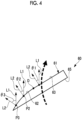
- an angle formed by a tangent line L1 to the virtual circle V and a normal line L2 to the collision surface 61 (hereinafter referred to as an "inclination angle ⁇ ") is larger on the outer side in the radial direction than on the inner side in the radial direction. That is, as shown in Fig. 4 , the curved surface 62 is curved such that an inclination angle ⁇ 3 at a point P3 outside a point P2 in the radial direction is larger than an inclination angle ⁇ 2 at the point P2.
- the curved surface shape of the curved surface 62 is determined by a required classification characteristic.
- the curved surface shape of the curved surface 62 has preferably a shape in which a radius of curvature is largest at the connection portion with the flat surface 63 and the farther away from the flat surface 63 (toward the outer side in the radial direction), the smaller the radius of curvature is.
- the curved surface 62 may have a constant curvature.
- the shape may be an arc shape, a shape of a part of an ellipse, or a parabolic shape.
- the classification characteristic is an index indicating how difficult it is for the crushed fuel to pass (be repelled to the outer periphery side of the blade 60), and is a value that increases as the crushed fuel becomes difficult to pass.
- the flat surface 63 is inclined at a predetermined angle with respect to the radial direction. Further, an inclination angle ⁇ 1 of the flat surface 63 is smaller than the inclination angle (for example, the inclination angle ⁇ 2 or the inclination angle ⁇ 3) of the curved surface 62.
- the virtual circle V is a virtual circle centered on the central axis C, and is also a rotation trajectory of any point in the blade cross section of the blade 60.
- the method for processing the blade 60 is not particularly limited.
- the blade 60 having a curved surface portion on the collision surface 61 may be processed by cutting a flat plate-shaped material.
- a curved surface portion may be formed on the collision surface of the blade by wear associated with the use of the rotary classifier 16 by appropriately selecting the material and hardness of the flat plate-shaped blade in consideration of a difference in wear rate according to the portion of the blade. That is, in a case where it is assumed that the contact frequency with the crushed particles and the wear rate increase toward the outer periphery in the radial direction of the blade, for example, if the surface hardness of the collision surface of the flat plate-shaped blade is uniform, a reduction in plate thickness due to wear increases toward the outer periphery side in the radial direction and a curved surface portion is formed according to use.
- the material or hardness of the blade 60 such that the curved surface portion is maintained by the wear of the blade 60 according to the use of the rotary classifier 16. By doing so, the maintenance frequency of the blade 60 can be reduced.
- the flat plate-shaped blade 60X is inclined at a predetermined angle with respect to the radial direction when viewed in a horizontal cross section.
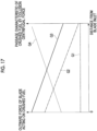
- the passage characteristic of the flat plate-shaped blade 60X at each position in the radial direction of the blade 60X shown by G4 in Fig. 17 is obtained.
- the passage characteristic is an index indicating how easily the crushed fuel passes through the classifier (a value that increases as it easily passes through the inner periphery side of the blade 60), and will be described in detail later.
- Fig. 17 shows the relationship between each position in the radial direction (a horizontal axis) of the blade 60X, the outward force (a left vertical axis) acting on the crushed fuel, and the passage characteristic (a right vertical axis) of the crushed fuel.
- the horizontal axis of the graph in Fig. 17 represents a distance from an inlet (an outer end in the radial direction) of the blade 60X.
- the horizontal axis represents a position in the radial direction of the blade 60X
- the left end of the horizontal axis represents the outer end in the radial direction of the blade 60X (the outer end of the blade 60X on the outer space S2 side)
- the right end represents the inner end in the radial direction of the blade 60X (the outer end of the blade 60X on the inner space S1 side).
- the outward force acting on the crushed fuel includes a force due to a centrifugal force and a force due to collision.
- the passage characteristic is positively correlated with the inward forces acting on the crushed fuel, and that is, it is negatively correlated with the outward forces (centrifugal force + collision force).
- G1 in Fig. 17 shows an outward force F3 (refer to Fig. 16 ) acting on the crushed fuel when the crushed fuel collides with the blade 60X. Further, G2 shows an outward force F5 (refer to Fig. 16 ) acting by a centrifugal force acting on the crushed fuel.
- the outward force F3 acting on the crushed fuel due to collision and the outward force F5 due to the centrifugal force acting on the crushed fuel are obtained as follows.
- the coarse powder fuel B1 is repelled to the outer side of the blade 60X (the outer space S2 side), as shown by an arrow A6.
- the pulverized fuel B2 is repelled to the inner side of the blade 60X (the inner space S1 side), as shown by an arrow A7.
- the force with which the crushed fuel collides with the rotating blade 60X is shown by an arrow F1.
- the force shown by the arrow F1 is decomposed into a force (arrow F2) acting in the vertical direction to the collision surface of the blade 60X and a force (arrow F3) acting in parallel along the collision surface of the blade 60X.
- the force acting in the vertical direction is canceled out by the action of a normal force (arrow F4) from the blade 60X. Since a counteracting force does not act on the force acting in parallel, the outward force F3 of the blade 60X acts on the colliding crushed fuel. That is, the outward force F3 due to the collision acts.
- an arrow F5 shows the outward force in the radial direction along the collision surface of blade 60X due to a centrifugal force
- an arrow F6 shows the inward force in the radial direction along the collision surface of blade 60X due to the flow of the primary air.
- the outward force F5 of the blade 60X acts as the inclination of the blade 60X with respect to the radial direction increases.
- the blade 60X has a flat plate shape. Therefore, in the blade 60X, the angle ⁇ is constant at any point in the radial direction. Therefore, as shown by G1 in Fig. 17 , the blade 60X has a constant outward force F5 at any point in the radial direction.
- the centrifugal force F5 acting on the crushed fuel colliding with the blade 60X having the same rotation speed is determined by the mass of the crushed fuel and the rotation radius of the collision position.
- the pulverized fuel B2 is small in mass. Further, as will be described later, the pulverized fuel B2 collides with the inner side in the radial direction of the blade 60X, that is, the portion having a small rotation radius, so that the centrifugal force F5 acting on the pulverized fuel B2 is reduced. Therefore, when the inward force F6 in the radial direction due to the flow of the primary air overcomes the centrifugal force F5, the pulverized fuel B2 moves to the inner side of the blade 60X in the radial direction.
- the coarse powder fuel B1 is large in mass. Further, as will be described later, the coarse powder fuel B1 collides with the outer side in the radial direction of the blade 60X, that is, the portion having a large rotation radius, so that the centrifugal force F5 acting on the coarse powder fuel B1 increases. Therefore, when the centrifugal force F5 overcomes the inward force F6 in the radial direction due to the flow of the primary air, the coarse powder fuel B1 is repelled to the outer side of the blade 60X in the radial direction.
- the force due to the centrifugal force F5 has a linear function, and thus becomes a straight line that slopes downward to the right.
- G3 in Fig. 17 shows the outward force by the sum of the outward force F5 due to the centrifugal force and the outward force F3 due to collision.
- the outward force F3 due to collision is constant, and therefore, as shown by G3 in Fig. 17 , the outward force (centrifugal force + collision force) becomes a straight line that slopes downward to the right.
- the passage characteristic shown by G4 in Fig. 17 is in an inversely proportional relationship (negative correlation) to the outward force (centrifugal force + collision force). Therefore, as shown by G4, the passage characteristic is a straight line that slopes upward to the right, whose slope is opposite to that of G3, which shows the outward force (centrifugal force + collision force).
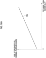
- the passage characteristic shown in Fig. 17 shows, that is, the mass of a single crushed fuel that can pass. If the density of the crushed fuel is constant, this shows the volume of the crushed fuel, that is, the size of the crushed fuel. Therefore, as shown by G5a in Fig. 18A , the passage characteristic and the size of the crushed fuel that passes are in a proportional relationship (positive correlation). Further, as shown by G4 in Fig. 17 , the passage characteristic is proportional to the distance from the outer end side of the blade 60X. From this, as shown by G5b in Fig. 18B , the size of the crushed fuel that passes is also proportional to the distance from the outer end side of the blade 60X. Fig.
- FIG. 18A is a graph showing the relationship between the size of the crushed fuel passing through the blade 60X and the passage characteristic.
- Fig. 18B is a graph showing the relationship between the size of the crushed fuel passing through the blade 60X and the distance from the inlet of the blade 60X.
- the crushed fuel is crushed on the crushing table 12 of the mill 10 and airflow-transported to the rotary classifier 16 by the primary air (carrier gas) that is blown from the periphery of the crushing table 12.
- an air flow E (the flow of the primary air) is a flow that rises while swirling inside the housing 11, and as shown in Fig. 19 , the air flow E reaches the rotary classifier 16 from the outer periphery side of the blade in the direction opposite to the rotation direction A1 of the blades 60X.
- the course of the air flow E reaching the side surface portion of the blade 60X is sharply bent toward the flow path between the blades 60X adjacent to each other, as shown in Fig. 19 .
- the pulverized fuel B2 which is light in mass and is small in inertia, easily changes the course along with the air flow E.
- the coarse powder fuel B1 which is heavy in mass and is large in inertia, is difficult to change the course. Due to this characteristic, as shown in Fig. 19 , the pulverized fuel B2 passes through the inner periphery side of the curve of the air flow, and the coarse powder fuel B1 passes through the outer periphery side of the curve of the air flow. In this way, rough classification by the air flow is performed.
- the proportion of the pulverized fuel B2 colliding with the outlet side (the inner side in the radial direction) of the blade 60X and the proportion of the coarse powder fuel B1 colliding with the inlet side (the outer side in the radial direction) of the blade 60X increases.
- Fig. 20 is a graph showing the relationship between the particle size of the crushed fuel colliding with the blade 60X and the distance from the inlet of the blade 60X.
- the distribution characteristic becomes a broad distribution with a certain width.
- the size of the particle of the crushed fuel that collides with each position in the radial direction of the blade 60X falls within a range shown by hatching in Fig. 20 .
- collision particle size distribution a case of colliding with the flat plate-shaped blade 60X has been described.
- the size of the particle of the crushed fuel that collides with the blade 60X does not change according to the shape of the blade. Therefore, for example, even in a case of colliding with the blade 60 provided with the curved surface 62 described in the present embodiment, the colliding particle size distribution becomes the distribution shown in Fig. 20 .
- the passage characteristic of the entire rotary classifier 16 provided with the flat plate-shaped blades 60X (that is, the classification performance of the rotary classifier 16) will be described using Fig. 21 .
- the left vertical axis represents the particle size of the crushed fuel that collides with the blade 60X
- the right vertical axis represent the particle size of the crushed fuel that passes through the blade 60X.
- the horizontal axis represents the distance from the inlet (outer end) of the blade 60X.
- the passage characteristic of the entire rotary classifier 16 in this description is derived from the size of the crushed fuel passing through the blades 60X shown by G5b in Fig. 18B and the crushed fuel distribution shown in Fig. 20 .
- the particle size of the crushed fuel at which G5b showing the size of the crushed fuel passing through the blade 60X and the upper edge line of the collision particle size distribution intersect each other is set as a target particle size of the rotary classifier 16.
- the target particle size is the upper limit value of the particle size of the crushed fuel that is to pass through the rotary classifier 16 and be discharged from the mill 10 (supplied to the burner 220 of the boiler 200).
- the region below G5b which shows the size of the crushed fuel passing through the upper edge line of the collision particle size distribution and the blade 60X, is the region of the crushed fuel that passes through the rotary classifier 16. That is, the region below a dashed line G6 is the region of the crushed fuel that passes through the rotary classifier 16.
- the passage characteristic on the blade inlet side (outer end side) where the coarse powder fuel is abundant is relatively low (that is, it is difficult to pass), and conversely, the passage characteristic on the blade outlet side (inner end side) where the pulverized fuel is abundant is relatively high (that is, it easily passes). In this way, the coarse powder fuel is not allowed to pass, and the pulverized fuel can be allowed to pass. Therefore, the classification effect can be obtained efficiently.
- the bent plate-shaped blade 60Y has a plate-shaped outer portion 60Ya and a plate-shaped inner portion 60Yb that are connected to form an angular bent point H.
- the blade 60Y has different inclination angles with respect to the radial direction between the outer portion 60Ya and the inner portion 60Yb. Further, the blade 60Y has a larger inclination angle at the outer portion 60Ya than at the inner portion 60Yb.
- the inclination angle of the inner portion 60Yb is the same as the inclination angle of the blade 60X described above will be described.
- the coarse powder fuel B1 is repelled to the outer side of the blade 60Y (the outer space S2 side), as shown by an arrow A8.
- the pulverized fuel B2 is repelled to the inner side of the blade 60Y (the inner space S1 side), as shown by an arrow A9.
- the blade 60Y has different inclination angles with respect to the radial direction between the outer portion 60Ya and the inner portion 60Yb. This means that the directions of the collision forces of the crushed fuel colliding with the blade 60Y are different. Therefore, the outward force (the force that is calculated by the above expression (1); refer to F3 in Fig. 16 ) acting on the crushed fuel that collides with the inner portion 60Yb having a small inclination angle is small, and the outward force acting on the particles colliding with the outer portion 60Ya having a large inclination angle is large.
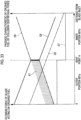
- G7 in Fig. 23 in the outer portion 60Ya of the blade 60Y, an outward force due to the collision force becomes larger, and in the inner portion 60Yb, an outward force due to the collision force becomes smaller.
- G2 in Fig. 23 shows an outward force due to the centrifugal force acting on the crushed fuel, similar to Fig. 17 .
- G8 shows an outward force by the sum of the outward force due to the centrifugal force and the outward force due to the collision force.
- G8 since the outward force due to the collision force greatly changes at the bent point H, G8 also greatly changes at the bent point H.
- the portion where the outward force greatly changes is referred to as a "stepped portion".
- the passage characteristic shown by G9 in Fig. 23 is in an inversely proportional relationship (negative correlation) to the outward force (centrifugal force + collision force).
- hatching K1 in Fig. 23 shows a region where a passage characteristic can be reduced as compared with the flat plate-shaped blade 60X. In this manner, in the outer portion 60Ya with which the coarse powder fuel B1 easily collide, the passage characteristic (the inward force) can be reduced, so that it can be seen that the passage of the coarse powder fuel B1 can be suppressed more than in the flat plate-shaped blade 60X.
- the passage characteristic of the entire rotary classifier 16 provided with the bent plate-shaped blade 60Y (that is, the classification performance of the rotary classifier 16) will be described using Fig. 24 .
- the passage characteristic of the entire rotary classifier 16 in this description is derived from G10, which shows the size of the crushed fuel passing through the blade 60Y based on G9 in Fig. 23 , and the collision particle size distribution shown in Fig. 20 .
- the region below G11 shown by a dashed line is a region of the crushed fuel that passes through the rotary classifier 16.
- the passage characteristic at the outer portion 60Ya is reduced compared to a case where the flat plate-shaped blade 60X is adopted. Further, the passage characteristic is extremely reduced in a region where the particle size is large, in particular, a region where the proportion of the particles equal to or smaller than the target particle size is very small. In this way, it is possible to suppress the passage of the coarse powder fuel and improve the classification performance.
- the crushed fuel is repelled to the outer periphery side by the blade 60Y even though it is within the range of the collision particle size distribution and is equal to or smaller than the target particle size. Therefore, it can be seen that the classification performance is reduced (the pulverized fuel that does not need to be classified and should be passed is repelled to the outer periphery side), compared to a case where the flat plate-shaped blade 60X is adopted.
- the repelled pulverized fuel is returned to the crushing table 12 and crushed again. Since the pulverized fuel that has already become finer is further crushed, in addition to the occurrence of waste of the crushing power, there is a problem that the returned pulverized fuel acts as a solid lubricant, so that slip vibration due to causing the crushing roller 13 to slip on the crushing table 12 easily occurs in the mill 10.
- the outward force due to the collision force also changes smoothly.
- the curved surface 62 has a larger inclination angle on the outer side in the radial direction than on the inner side in the radial direction. Therefore, the outward force due to the collision force increases toward the outer side in the radial direction.
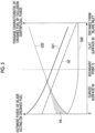
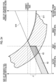
- G21 showing the outward force by the sum of the outward force due to the centrifugal force and the outward force due to the collision force also changes smoothly such that the outward force increases toward the outer side in the radial direction.
- FIG. 5 shows the outward force due to the centrifugal force acting on the crushed fuel, similar to Fig. 17 and the like.
- the passage characteristic shown by G22 in Fig. 5 is in an inversely proportional relationship (negative correlation) to the outward force (centrifugal force + collision force). Therefore, similar to G21, G22 also changes smoothly.
- hatching K4 in Fig. 5 shows a region where the passage characteristic can be reduced more than in the flat plate-shaped blade 60X. In this manner, since the passage characteristic (the inward force) can be reduced on the outer side in the radial direction, with which the coarse powder fuel B1 easily collides, a situation where the coarse powder fuel B1 passes more than in the flat plate-shaped blade 60X can be suppressed.
- the passage characteristic of the entire rotary classifier 16 provided with the blade 60 according to the present embodiment (that is, the classification performance of the rotary classifier 16) will be described using Fig. 6 .
- the passage characteristic of the entire rotary classifier 16 in this description is derived from G23, which shows the size of the crushed fuel passing through the blades 60 based on G22 in Fig. 5 , and the collision particle size distribution shown in Fig. 20 .
- the region below a dashed line G24 is the region of the crushed fuel passing through the rotary classifier 16.
- the passage characteristic is reduced on the curved surface 62, compared to a case where the flat plate-shaped blade 60X is adopted.
- the passage characteristic is reduced on the curved surface 62, compared to a case where the bent plate-shaped blade 60Y is adopted.
- the passage characteristic is extremely reduced in a region where the particle size is large, in particular, a region where the proportion of the particles equal to or smaller than the target particle size is very small. In this way, it is possible to further suppress the passage of the coarse powder fuel and improve the classification performance.
- the amount of crushed fuel that is not completely burned in the burner 220 (unburned crushed fuel) can be reduced, and an unburned content in the ash discharged from the boiler 200 can be reduced.
- the amount of air that is supplied to the boiler 200 can be reduced (low air ratio combustion is possible), and the amount of nitrogen oxides that are produced can also be suppressed. Therefore, an environmental load can be reduced. Further, the amount of reducing agent (ammonia or the like) that is used in the denitration device 35 can be reduced, and thus the running cost can be reduced.
- the crushed fuel is repelled to the outer periphery side by the blade 60Y even though it is within the range of the collision particle size distribution and is equal to or smaller than the target particle size.
- the region where the classification performance is lowered can be reduced compared to a case where the bent plate-shaped blade 60Y is adopted (refer to the hatching K3 in Fig. 24 ). Therefore, a decrease in classification performance can be suppressed.
- the stepped portion that occurs in a case where the bent plate-shaped blade 60Y is adopted is eliminated. In this way, the region where whether or not the particles are classified is random with respect to the particle size can be eliminated, so that the classification performance can be improved.
- the curved surface 62 is formed on the outer side in the radial direction of the blade 60.
- the curved surface shape is generally maintained. That is, in the curved surface tip type blade 60, the blade 60 can have a self-shaping property in which it wears to reduce a length in the radial direction.
- the collision surface 61 has the curved surface 62 and the flat surface 63. Since the flat surface 63 is easier to be manufactured than the curved surface 62, the blade 60 can be more easily manufactured compared to a case where the entire collision surface 61 is the curved surface 62.
- the inner side in the radial direction of the collision surface 61 is greatly affected by the force of the primary air (that is, the force heading from the outer side of the blade 60 in the radial direction to the inner side of the blade 60 in the radial direction), and therefore, the influence of the outward force due to the collision force of the crushed fuel is reduced.
- the flat surface 63 is formed on the inner side in the radial direction. In this way, a decrease in classification performance can be suppressed compared to a case where the flat surface 63 is formed on the outer side in the radial direction.
- the boundary point D which is the boundary between the curved surface 62 and the flat surface 63, may be on the inner side in the radial direction with respect to a point L where G23 showing the size of the crushed fuel passing through the blade 60 in Fig. 6 and the upper edge line of the collision particle size distribution intersect each other.
- the length in the circumferential direction (the length in the plate thickness direction) of the blade 60 becomes shorter toward the outer side in the radial direction. In this way, since the plate thickness of the blade 60 can be reduced, it is possible to make it difficult for a tool or the like to interfere with an adjacent blade or the like when mounting the blade 60. Therefore, the work of mounting the blade 60 can be facilitated.
- the present disclosure is not limited to the above embodiments, and can be appropriately modified within a scope which does not depart from the gist of the present disclosure.
- the mill of the present disclosure is used.
- solid fuel biomass fuel or PC (petroleum coke) fuel generated during petroleum refining may be used, and a combination of these fuel may be used.
- PC molecular coke
- the classifier of the present disclosure is applied to a mill that crushes solid fuel.
- the present disclosure is not limited to this.
- the classifier of the present disclosure may be applied to crushing devices that crush ore.
- the length in the radial direction of the blade 60 is reduced with wear. Therefore, it is desirable to set a replacement reference by the length in the radial direction.
- the blade 60 may be provided with detection means for detecting the length in the radial direction, and this detection means may be used as a wear detection sensor.
- the blade 60 is preferably detachably fixed to the main body portion 70 with bolts or the like such that it can be replaced when worn.
- the blade 60 in a case where the blade 60 is made of a material with sufficient wear resistance, it may be fixed by welding or the like.
- a mounting surface and a bolt seating surface where the blade 60 is mounted to the main body portion 70 are provided on the flat surface 63 of the blade 60.
- the mounting surface or the like may be provided on the curved surface 62.
- a counterbore or the like may be provided, or the seating surface may be formed using a washer or the like that matches the curvature.
- the blade may be manufactured by laminating a plurality of thin plate members in the plate thickness direction.
- a blade 60A is formed by stacking thin plate members (60Aa, 60Ab, and 60Ac) having different lengths in the radial direction.
- Each plate member may be made of the same material, or may be made of a different material. In a case where the plate materials are formed of different materials, each plate member may be disposed such that plate members formed of a material having higher wear resistance are disposed from the collision surface 61 side toward the back surface 65 side. By doing so, the self-shaping property can be exhibited more suitably.
- the blade may have a constant length in the circumferential direction (plate thickness) over the entire area in the radial direction.
- the curved surface 62 is formed on the collision surface 61 by bending a flat plate-shaped blade. In this manner, in the present modification example, the blade 60B having a curved surface can be formed simply by bending, so that the blade 60B can be easily manufactured.
- the length in the circumferential direction (plate thickness) of the blade 60B is constant over the entire area in the radial direction, the length in which wear is allowable is increased over the entire area in the radial direction. Therefore, the durability of the blade 60B can be improved.
- the blade may have a plurality of recessed portions 80 formed in the curved surface 62.
- a blade 60C has a constant length in the circumferential direction (plate thickness) over the entire area in the radial direction, and the plurality of recessed portions 80 are formed in the curved surface 62.
- the recessed portion 80 for example, a dimple can be given.
- the blade 60C has a self-lining structure configured due to the plurality of recessed portions 80.
- the recessed portion 80 is formed to have a radius of curvature sufficiently small compared to the radius of curvature of the curved surface 62. That is, the recessed portion 80 has a size to the extent that does not affect a trend of the shape of the curved surface 62. Specifically, for example, in a case where the radius of curvature R of the curved surface 62 is 100, when the radius of curvature R of the recessed portion 80 is about 10 or less, the trend of the shape of the curved surface 62 is not affected.
- the recessed portions 80 are formed in the curved surface 62, so that the crushed fuel enters the recessed portions 80. In this way, the surface of the curved surface 62 is covered with the crushed fuel. Due to the crushed fuel covering the surface of the curved surface 62, contact between the flowing crushed fuel and the curved surface 62 is suppressed. Therefore, wear of the curved surface 62 can be suppressed.
- the recessed portions 80 or the waves may be provided not only on the curved surface 62 but also on the flat surface 63, and by providing them on the collision surface 61, wear can be suppressed.
- the blade 60 has a uniform shape in the up-down direction.
- the present disclosure is not limited to this.
- the cross-sectional shape of a blade 60D may smoothly change in the up-down direction. That is, as shown in Fig. 10 , the cross-sectional shape of the upper portion (refer to Fig. 11 ) of the blade 60D and the cross-sectional shape of the lower portion (refer to Fig. 12 ) may be different.
- the blade 60D has a curved surface in which the cross-sectional shape in the upper portion is smaller than the cross-sectional shape in the lower portion.
- the curved surface 62 is made large to make it easier to repel the crushed fuel to the outer side in the radial direction, so that it is possible to sufficiently repel the crushed fuel to the outer side in the radial direction. Therefore, in the example shown in Fig. 10 , even in a case where the blade 60D is inclined with respect to the up-down direction, an aspect in which the crushed fuel is repelled to the outer side in the radial direction can be made uniform in the up-down direction.
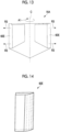
- the shape may be uniform in the up-down direction as shown in Fig. 14 .
- the structure can be simplified, so that it can be easily manufactured.
- the blade may have a rectangular cross-sectional shape without forming curved surfaces at the upper end portion and the lower end portion which are fixed to the upper end portion 72 and the lower end portion 73 of the main body portion 70. By doing so, the surface of the blade which is fixed to the main body portion 70 can be increased compared to a case where the curved surface is formed. Therefore, the blade can be firmly fixed.
- the curved surface 62 does not need to be a perfect curved surface, and a curved surface may be formed digitally by combining planes with minute angle differences or by combining thin layers in a stepwise manner. Further, depending on the required classification performance, a flat surface may be inserted into the tip of the curved surface 62 or a part of the middle of the curved surface 62.
- the classifier, the power plant, and the method for operating a classifier according to the embodiments described above are understood as follows, for example.
- a classifier is a classifier (16) that classifies particles introduced along with a carrier gas into particles larger than a predetermined particle size and particles equal to or smaller than the predetermined particle size, the classifier (16) including a plurality of blades (60) that extend in an up-down direction and are disposed side by side in a circumferential direction on a virtual circle (V) centered on a central axis (C) extending in the up-down direction, and to which the particles are introduced along with the carrier gas heading from an outer side in a radial direction to an inner side, in which the blade (60) has a collision surface (61) with which the introduced particles collide, and which repels the particles larger than the predetermined particle size, among the collided particles, in an outward direction in the radial direction, and repels the particles equal to or smaller than the predetermined particle size in an inward direction in the radial direction, and in the collision surface (61), an angle formed by a tangent line to the virtual circle (V)
- the crushed solid fuel (hereinafter referred to as "crushed fuel”) having a larger particle size tends to easily collide with the outer side in the radial direction, and the crushed fuel having a smaller particle size tends to easily collide with the inner side in the radial direction.
- the greater the angle formed by the tangent line to the virtual circle and the normal line to the collision surface (hereinafter referred to as an "inclination angle"), the more strongly the crushed fuel is repelled to the outer side in the radial direction.
- the collision surface of the blade has a larger inclination angle on the outer side in the radial direction than on the inner side in the radial direction. That is, a shape is formed in which a force that repels the crushed fuel to the outer side in the radial direction is strong on the outer side in the radial direction, with where the crushed fuel having a large particle size easily collides. Therefore, the crushed fuel having a large particle size can be strongly repelled to the outer side in the radial direction.
- the collision surface of the blade has a small inclination angle on the inner side in the radial direction than on the outer side in the radial direction.
- a shape is formed in which a force that repels the crushed fuel to the outer side in the radial direction is weak on the inner side in the radial direction, with where the crushed fuel having a small particle size easily collides. Therefore, the crushed fuel having a small particle size is easily led to the inner side in the radial direction along with the carrier gas heading from the outer side in the radial direction to the inner side in the radial direction. In this way, the crushed fuel having a small particle size can be repelled to the inner side in the radial direction.
- the classification performance of the classifier can be improved.
- the collision surface (61) has a curved surface (62) curved to protrude, and in the curved surface (62), the angle formed by the tangent line to the virtual circle (V) and the normal line to the collision surface (61) is larger on the outer side in the radial direction than on the inner side in the radial direction.
- the blade has a bent plate shape in which a flat plate-shaped outer portion and a flat plate-shaped inner portion having different inclination angles are connected
- whether the crushed fuel collides with the outer portion and is repelled to the outer side of the blade or the crushed fuel collides with the inner portion and is repelled to the inner side of the blade is determined according to an intrusion position of the crushed fuel. Therefore, even if it is the crushed fuel having the same particle size, a case where it is classified (a case of being repelled to the outer side) or a case where it is not classified (a case of being repelled to the outer side) occur according to the intrusion position. Therefore, there is a possibility that the classification performance may decrease.
- the collision surface is curved. In this way, it is possible to reduce s region that depends on an intrusion position. Therefore, the classification performance can be improved.
- the curved surface of the blade has a larger inclination angle on the outer side in the radial direction than on the inner side in the radial direction. That is, a shape is formed in which a force that repels the crushed fuel to the outer side in the radial direction is strong on the outer side in the radial direction, with where the crushed fuel having a large particle size easily collides. Therefore, the crushed fuel having a large particle size can be strongly repelled to the outer side in the radial direction.
- the curved surface of the blade has a small inclination angle on the inner side in the radial direction than on the outer side in the radial direction.
- a shape is formed in which a force that repels the crushed fuel to the outer side in the radial direction is weak on the inner side in the radial direction, with where the crushed fuel having a small particle size easily collides. Therefore, the crushed fuel having a small particle size is easily led to the inner side in the radial direction along with the carrier gas heading from the outer side in the radial direction to the inner side in the radial direction. In this way, the crushed fuel having a small particle size can be repelled to the inner side in the radial direction.
- the classification performance of the classifier can be improved.
- the curved surface includes a polygonal surface formed by combining planes having a minute angle difference, or a stepped surface formed by laminating thin layers with end portions shifted.
- the collision surface (61) has the curved surface (62) and a flat surface (63) disposed on the inner side in the radial direction with respect to the curved surface (62).
- the collision surface has the curved surface and the flat surface. Since the flat surface is easier to be manufactured than the curved surface, the blade can be manufactured more easily compared to a case where the entire surface of the collision surface is a curved surface.
- the inner side in the radial direction of the collision surface is greatly affected by the force of the carrier gas (that is, the force heading from the outer side in the radial direction to the inner side), and therefore, the influence of a repelling force in the outward direction by the inclination angle is reduced.
- the flat surface is formed on the inner side in the radial direction, a decrease in classification performance due to forming the flat surface can be suppressed.
- a length in the circumferential direction of the blade (60) becomes shorter toward the outer side in the radial direction.
- the length in the circumferential direction (the length in the plate thickness direction) of the blade becomes shorter toward the outer side in the radial direction. In this way, since the plate thickness of the blade can be reduced, it is possible to make it difficult for a tool or the like to interfere with an adjacent blade or the like when mounting the blade. Therefore, the work of mounting the blade can be facilitated.
- a length in the circumferential direction of the blade (60) is constant over an entire area in the radial direction.
- the length in the circumferential direction (the length in the plate thickness direction) of the blade is constant over the entire area in the radial direction.
- the blade having the curved surface can be manufactured by bending a flat plate-shaped blade. Therefore, the blade can be manufactured easily.
- the length in the circumferential direction (the length in the plate thickness direction) of the blade is constant over the entire area in the radial direction, a length in which wear is allowable increases. Therefore, durability of the blade can be improved.
- a plurality of recessed portions are formed in the collision surface (61).
- the plurality of recessed portions are formed in the collision surface. That is, a self-lining structure is configured by the plurality of recessed portions. In this way, the crushed fuel enters the recessed portions, so that the crushed fuel covers the surface of the collision surface. The contact between the flowing crushed fuel and the collision surface is suppressed by the crushed fuel covering the surface of the collision surface. Therefore, wear of the collision surface can be suppressed.
- a power plant includes: the classifier (16) according to any one of the above; a boiler (200) that burns crushed solid fuel equal to or smaller than a predetermined particle size classified by the classifier (16); and a power generation part that generates electric power by using steam produced by the boiler (200).
- a method for operating a classifier is a method for operating a classifier (16) that classifies particles introduced along with a carrier gas into particles larger than a predetermined particle size and particles equal to or smaller than the predetermined particle size, in which the classifier (16) includes a plurality of blades (60) that extend in an up-down direction and are disposed side by side in a circumferential direction on a virtual circle (V) centered on a central axis extending in the up-down direction, and to which the particles are introduced along with the carrier gas heading from an outer side in a radial direction to an inner side, the blade (60) has a collision surface (61) with which the introduced particles collide, and which repels the particles larger than the predetermined particle size, among the collided particles, in an outward direction in the radial direction, and repels the particles equal to or smaller than the predetermined particle size in an inward direction in the radial direction, and in the collision surface (61), an angle formed by a collision surface (61) with which the introduced particles coll
Landscapes
- Engineering & Computer Science (AREA)
- Mechanical Engineering (AREA)
- General Engineering & Computer Science (AREA)
- Food Science & Technology (AREA)
- Crushing And Grinding (AREA)
- Combined Means For Separation Of Solids (AREA)
Abstract
Description
- The present disclosure related to a classifier, a power plant, and a method for operating a classifier.
- In the related art, solid fuel (carbon-containing solid fuel) such as coal or biomass fuel is crushed by a pulverizer (mill) into fine powder within a predetermined particle size range and supplied to a combustion device. In the mill, the solid fuel such as coal or biomass fuel put into a crushing table is sandwiched and crushed between the crushing table and a crushing roller, and the pulverized fuel within a predetermined particle size range (fineness), of the solid fuel crushed into fine powder (hereinafter, the crushed solid fuel is referred to as "crushed fuel"), is sorted in a classifier by a carrier gas (primary air) that is supplied from an outer periphery of the crushing table, and transported to a boiler to be burned in a combustion device. In a thermal power plant, steam is generated by heat exchange with a combustion gas produced by burning pulverized fuel in a boiler, and a steam turbine is rotationally driven by the steam to rotationally drive a generator connected to the steam turbine, whereby electric power generation is performed.
- As one of the classifiers that are provided in the mill, for example, a rotary classifier is known. The rotary classifier has a plurality of blades that are disposed at equal intervals in the circumferential direction around a rotational axis. The rotary classifier is a device that performs classification by causing coarse powder fuel (crushed fuel larger than a predetermined particle size), which is large in weight and on which a centrifugal force acts greatly, to repel to the outer periphery side of the blade, and causing pulverized fuel (crushed fuel smaller than a predetermined particle size), which is small in weight and on which a transport force due to an air flow of primary air acts greatly, to pass to the inner periphery side of the blade, when the crushed fuel passes between the plurality of blades that rotate around the rotational axis.
- Further, the rotary classifier has a main body portion that rotates around the rotational axis. The main body portion holds the upper and lower sides of the blade, so that the blade can revolve around the rotational axis. The main body portion is held by bearings and rotated at a predetermined rotation speed by a power source such as a motor. By changing the rotation speed, the force acting on the crushed fuel can be adjusted to obtain a predetermined fineness (classification performance).
- In general, the blade of the rotary classifier has a flat plate shape. However, for the purpose of improving classification performance (the performance of repelling coarse powder fuel to the outer periphery side of the blade and passing pulverized fuel between the blades) or the like, there is a case where the blade of the rotary classifier is made in a shape that is not a simple flat plate shape (for example, PTL 1).
- In PTL 1, there is described a rotary classifier in which an angle with a direction of a rotation radius is large at an upstream end (an inlet end) of each of a plurality of classifying blades rotating around a vertical axis and the angle is small at a downstream end (an outlet end). That is, in PTL 1, there is described a rotary classifier in which a classifying blade is bent.
- [PTL 1]
Japanese Unexamined Patent Application Publication No. H7-51630 - The classifying blade (blade) described in PTL 1 has a shape that is bent such that an inlet side portion (an outer portion in the radial direction) and an outlet side portion (an inner portion in the radial direction) have different angles (angles with respect to the radial direction). In general, a particle size range of the crushed fuel that can be repelled toward the outer periphery side changes according to the angle of the blade. Therefore, in the blade described in PTL 1, there is a case where crushed fuel having a particle size of an intermediate degree, which is repelled to the outer periphery side at the inlet side portion of the blade but cannot be repelled to the outer periphery side at the outlet side portion, collides with the blade. In this case, the result of classification is greatly different between a case of colliding with the outlet side portion and a case of colliding with the inlet side portion.
- Whether to collide with the inlet side portion of the blade or to collide with the outlet side portion is determined by an intrusion position of the crushed fuel into the rotary classifier. Specifically, in a case of intruding into the rotary classifier from a distant place in the radial direction of the blade, the crushed fuel collides with the outlet side portion, and in a case of intruding into the rotary classifier from a near place in the radial direction of the blade, the crushed fuel collides with the inlet side portion.
- In this manner, in the device described in PTL 1, in a case where crushed fuel having a particle size of an intermediate degree intrudes into the rotary classifier from a distant place of the blade and collides with the inlet side portion of the blade, the collided crushed fuel is repelled to the outer periphery side to be returned to a crushing part (a crushing table). On the other hand, in a case where crushed fuel having a particle size of an intermediate degree intrudes into the rotary classifier from a near place of the blade and collides with the outlet side portion of the blade, the collided crushed fuel passes to the inner periphery side and is led to a boiler. Since it is difficult to control the intrusion position of the crushed fuel into the rotary classifier, in the device described in PTL 1, with respect to the crushed fuel having a particle size of an intermediate degree, whether it collides with the inlet side portion and is repelled to the outer periphery side or it collides with the outlet side portion and passes to the inner periphery side is random with respect to the particle size. That is, even if it is the crushed fuel having the same particle size, a case where it is classified (a case where it is repelled to the outer periphery side) and a case where it is not classified (a case where it is repelled to the inner periphery side) occur. Therefore, there is a possibility that the classification of the crushed fuel according to a target particle size may not be performed with high accuracy, that is, the classification performance may decrease.
- In particular, since the larger the angle difference between the inlet side portion and the outlet side portion, the larger the particle size range in which whether or not to be classified becomes random with respect to the particle size, a decrease in classification performance is remarkable. Further, even if the rotation speed of the blade is changed, a problem of a decrease in classification performance cannot be solved only by changing the upper limit or lower limit of the particle size range in which whether or not to be classified becomes random with respect to the particle size.
- The present disclosure has been made in view of such circumstances, and has an object to provide a classifier, a power plant, and a method for operating a classifier, in which it is possible to improve classification performance. Solution to Problem
- In order to solve the above problems, a classifier, a power plant, and a method for operating a classifier of the present disclosure adopt the following means.
- A classifier according to an aspect of the present disclosure is a classifier that classifies particles introduced along with a carrier gas into particles larger than a predetermined particle size and particles equal to or smaller than the predetermined particle size, the classifier including: a plurality of blades that extend in an up-down direction and are disposed side by side in a circumferential direction on a virtual circle centered on a central axis extending in the up-down direction, and to which the particles are introduced along with the carrier gas heading from an outer side in a radial direction to an inner side, in which the blade has a collision surface with which the introduced particles collide, and which repels the particles larger than the predetermined particle size, among the collided particles, in an outward direction in the radial direction, and repels the particles equal to or smaller than the predetermined particle size in an inward direction in the radial direction, and in the collision surface, an angle formed by a tangent line to the virtual circle and a normal line to the collision surface is larger on an outer side in the radial direction than on an inner side in the radial direction.
- A method for operating a classifier according to an aspect of the present disclosure is a method for operating a classifier that classifies particles introduced along with a carrier gas into particles larger than a predetermined particle size and particles equal to or smaller than the predetermined particle size, in which the classifier includes a plurality of blades that extend in an up-down direction and are disposed side by side in a circumferential direction on a virtual circle centered on a central axis extending in the up-down direction, and to which the particles are introduced along with the carrier gas heading from an outer side in a radial direction to an inner side, the blade has a collision surface with which the introduced particles collide, and which repels the particles larger than the predetermined particle size, among the collided particles, in an outward direction in the radial direction, and repels the particles equal to or smaller than the predetermined particle size in an inward direction in the radial direction, and in the collision surface, an angle formed by a tangent line to the virtual circle and a normal line to the collision surface is larger on an outer side in the radial direction than on an inner side in the radial direction, the method including: a step of classifying the particles into the particles larger than the predetermined particle size and the particles equal to or smaller than the predetermined particle size by the blade.
- According to the present disclosure, it is possible to improve classification performance.
-
-
Fig. 1 is a configuration diagram showing a solid fuel crushing device and a boiler according to an embodiment of the present disclosure. -
Fig. 2 is a vertical sectional view showing a rotary classifier according to the embodiment of the present disclosure. -
Fig. 3 is a horizontal sectional view showing the rotary classifier according to the embodiment of the present disclosure. -
Fig. 4 is a horizontal sectional view showing a blade according to the embodiment of the present disclosure. -
Fig. 5 is a graph showing the relationship between an outward force and passage characteristic of the blade, which acts on crushed fuel, and a distance from a blade inlet in the embodiment of the present disclosure. -
Fig. 6 is a graph showing classification performance of the rotary classifier according to the embodiment of the present disclosure. -
Fig. 7 is a diagram showing a modification example of the blade according to the embodiment of the present disclosure. -
Fig. 8 is a diagram showing a modification example of the blade according to the embodiment of the present disclosure. -
Fig. 9 is a diagram showing a modification example of the blade according to the embodiment of the present disclosure. -
Fig. 10 is a diagram showing a modification example of the blade according to the embodiment of the present disclosure. -
Fig. 11 is a sectional view taken along line XI-XI ofFig 10 and viewed in the direction of an arrow. -
Fig. 12 is a sectional view taken along line XII-XII ofFig 10 and viewed in the direction of an arrow. -
Fig. 13 is a diagram showing a modification example of the rotary classifier according to the embodiment of the present disclosure. -
Fig. 14 is a diagram showing a modification example of the blade according to the embodiment of the present disclosure. -
Fig. 15 is a diagram showing a blade according to a comparative example of the present disclosure. -
Fig. 16 is a diagram showing the blade according to the comparative example of the present disclosure. -
Fig. 17 is a graph showing the relationship between an outward force and passage characteristic of the blade, which acts on crushed fuel, and a distance from a blade inlet in the comparative example of the present disclosure. -
Fig. 18A is a graph showing the relationship between a size of crushed fuel passing through a flat plate-shaped blade and the passage characteristic. -
Fig. 18B is a graph showing the relationship between the size of the crushed fuel passing through the flat plate-shaped blade and the distance from the blade inlet. -
Fig. 19 is a schematic diagram showing a classification effect in an air flow. -
Fig. 20 is a graph showing the relationship between a particle size of crushed fuel that collides with the blade and the distance from the blade inlet. -
Fig. 21 is a graph showing classification performance of a rotary classifier according to the comparative example of the present disclosure. -
Fig. 22 is a diagram showing a blade according to a comparative example of the present disclosure. -
Fig. 23 is a graph showing the relationship between an outward force and passage characteristic of the blade, which acts on crushed fuel, and a distance from a blade inlet in the comparative example of the present disclosure. -
Fig. 24 is a graph showing classification performance of a rotary classifier according to the comparative example of the present disclosure. - Hereinafter, an embodiment of the present disclosure will be described with reference to the drawings. A power plant 1 according to the present embodiment includes a solid
fuel crushing device 100 and aboiler 200. - In the following description, upper indicates a vertically upper side, and "upper" in an upper portion, an upper surface, or the like indicates a portion on the vertically upper side. Further, similarly, "lower" indicates a portion on the vertically lower side, and a vertical direction is not exact and includes an error.
- The solid
fuel crushing device 100 of the present embodiment is a device that crushes solid fuel (carbon-containing solid fuel) such as coal or biomass fuel, as an example, to generate pulverized fuel, and supplies the pulverized fuel to a burner (a combustion device) 220 of theboiler 200. - Although the power plant 1 that includes the solid
fuel crushing device 100 and theboiler 200 shown inFig. 1 includes a single solidfuel crushing device 100, a system may be adopted in which a plurality of solidfuel crushing devices 100 are provided respectively corresponding to a plurality ofburners 220 of asingle boiler 200. - The solid
fuel crushing device 100 of the present embodiment includes a mill(a pulverizer) 10, a coal feeder (a fuel feeder) 20, an air blowing part (a carrier gas supply part) 30, astate detecting part 40, and a control unit (determination unit) 50. - The
mill 10 that crushes solid fuel such as coal or biomass fuel to be supplied to theboiler 200 into pulverized fuel, which is finely powdered solid fuel, may be of a type of crushing only coal, a type of crushing only biomass fuel, or a type of crushing biomass fuel together with coal. - Here, the biomass fuel is a renewable organic resource derived from living organisms, and is, for example, thinned wood, waste wood, driftwood, grass, waste, sludge, tires, recycled fuel (pellets or chips) made using these as raw materials, or the like. However, it is not limited to those presented here. Since the biomass fuel takes in carbon dioxide during a growth process of biomass, it is considered to be carbon-neutral because it does not emit carbon dioxide that is a global warming gas.
- The
mill 10 includes ahousing 11, a crushing table (a rotary table) 12, a crushingroller 13, adrive unit 14, amill motor 15 that is connected to thedrive unit 14 and rotationally drives the crushing table 12, arotary classifier 16, afuel supply part 17, and aclassifier motor 18 that rotationally drives therotary classifier 16. - The
housing 11 is a casing that is formed in a tubular shape extending in the vertical direction and accommodates the crushing table 12, the crushingroller 13, therotary classifier 16, and thefuel supply part 17. - The
fuel supply part 17 is mounted to a central portion of aceiling portion 42 of thehousing 11. Thefuel supply part 17 is for supplying the solid fuel introduced from abunker 21 into thehousing 11, and is disposed along an up-down direction at a center position of thehousing 11, and a lower end portion thereof extends to the inside of thehousing 11. - The
drive unit 14 is installed in the vicinity of abottom surface portion 41 of thehousing 11, and the crushing table 12 that is rotated by a driving force that is transmitted from themill motor 15 connected to thedrive unit 14 is disposed to be rotatable. - The crushing table 12 is a circular member when viewed in a plan view, and is disposed such that the lower end portion of the
fuel supply part 17 faces it. The upper surface of the crushing table 12 may have, for example, an inclined shape in which a central portion is low and it becomes higher toward the outer side to form a shape in which an outer peripheral portion is bent upward. Thefuel supply part 17 supplies solid fuel (in the present embodiment, for example, coal or biomass fuel) from above toward the crushing table 12 below, and the crushing table 12 crushes the supplied solid fuel between itself and the crushingroller 13. - When the solid fuel is introduced from the
fuel supply part 17 toward a substantially central region of the crushing table 12, the solid fuel is led toward the outer periphery side of the crushing table 12 by a centrifugal force due to the rotation of the crushing table 12, and is sandwiched and crushed between the crushing table 12 and the crushingroller 13. The crushed solid fuel is blown upward by a carrier gas (hereinafter referred to as primary air) introduced from a carriergas flow path 100a (hereinafter referred to as a primary air flow path), and is led to therotary classifier 16. - A discharge outlet (not shown) that allows the primary air flowing in from the primary
air flow path 100a to flow out to a space above the crushing table 12 in thehousing 11 is provided at the outer periphery of the crushing table 12. A swirl blade (not shown) is installed at the discharge outlet to impart a swirling force to the primary air blown out from the discharge outlet. The primary air with the swirling force applied thereto by the swirl blade becomes an air flow having a swirling velocity component, and transports the solid fuel crushed on the crushing table 12 to therotary classifier 16 on the upper side in thehousing 11. The solid fuel larger than a predetermined particle size, of the crushed solid fuel, is classified by therotary classifier 16, or falls to be returned to the crushing table 12 without reaching therotary classifier 16 and crushed between the crushing table 12 and the crushingroller 13 again. - The crushing
roller 13 is a rotating body that crushes the solid fuel supplied from thefuel supply part 17 to the crushing table 12. The crushingroller 13 is pressed against the upper surface of the crushing table 12 and crushes the solid fuel in cooperation with the crushing table 12. - Although in
Fig. 1 , only one crushingroller 13 is shown as a representative, a plurality of crushingrollers 13 are disposed at constant intervals in a circumferential direction so as to press the upper surface of the crushing table 12. For example, three crushingrollers 13 are disposed at equal intervals in the circumferential direction at angular intervals of 120° on an outer peripheral portion. In this case, the portions (pressing portions) where the three crushingrollers 13 are in contact with the upper surface of the crushing table 12 are equidistant from a rotation center axis of the crushing table 12. - The crushing
roller 13 can be swung up and down by ajournal head 45 and is supported to be movable toward and away from the upper surface of the crushing table 12. When the crushing table 12 rotates in a state where an outer peripheral surface of the crushingroller 13 is in contact with the solid fuel on the upper surface of the crushing table 12, the crushingroller 13 receives a rotational force from the crushing table 12 and rotates together with the crushing table 12. When the solid fuel is supplied from thefuel supply part 17, the solid fuel is pressed and crushed between the crushingroller 13 and the crushing table 12. - A
support arm 47 of thejournal head 45 is supported by asupport shaft 48 along a horizontal direction at its intermediate portion such that the crushingroller 13 can swing in the up-down direction with thesupport shaft 48 as a center at a side surface portion of thehousing 11. Further, apressing device 49 is provided at an upper end portion of thesupport arm 47 on the vertically upper side. Thepressing device 49 is fixed to thehousing 11 and applies a load to the crushingroller 13 through thesupport arm 47 or the like so as to press the crushingroller 13 against the crushing table 12. - The
drive unit 14 is a device that transmits a driving force to the crushing table 12 and rotates the crushing table 12 around the central axis thereof. Thedrive unit 14 is connected to themill motor 15 and transmits the driving force of themill motor 15 to the crushing table 12. - The
rotary classifier 16 is provided at an upper portion of thehousing 11 and has a hollow and substantially inverted conical outer shape. Therotary classifier 16 has, at positions on an outer periphery thereof, a plurality ofblades 60 extending in the up-down direction. Theblades 60 are provided at predetermined intervals (equal intervals) around a central axis C of therotary classifier 16. - The
rotary classifier 16 is a device that classifies the solid fuel (hereinafter, the crushed solid fuel is referred to as "crushed fuel") crushed by the crushing table 12 and the crushingroller 13 into fuel larger than a predetermined particle size (for example, a range of 70 to 100 um in coal) (hereinafter, the crushed fuel exceeding a predetermined particle size will be referred to as "coarse powder fuel") and fuel equal to or smaller than the predetermined particle size (hereinafter, the crushed uel equal to or smaller than the predetermined particle size will be referred to as "pulverized fuel"). Therotary classifier 16, which classifies the solid fuel by rotation, is also called a rotary separator, and is provided with a rotational driving force by theclassifier motor 18 that is controlled by thecontrol unit 50 to rotate around thefuel supply part 17 with a cylindrical shaft 71 (refer toFig. 2 ) extending in the up-down direction of thehousing 11 as a center. Details of therotary classifier 16 will be described later. - As the classifier, a fixed classifier having a fixed hollow inverted conical casing and a plurality of fixed swirl blades instead of the
blades 60 at positions on an outer periphery of the casing may be used. - The large-diameter coarse powder fuel of the crushed fuel that reaches the
rotary classifier 16 is knocked down by theblade 60 due to the relative balance between a centrifugal force generated by the rotation of theblade 60 and a centripetal force caused by the primary air flow, and returned to the crushing table 12 to be crushed again, and the pulverized fuel is led to anoutlet port 19 in theceiling portion 42 of thehousing 11. The pulverized fuel classified by therotary classifier 16 is discharged together with the primary air from theoutlet port 19 to a pulverized fuelsupply flow path 100b and supplied to theburner 220 of theboiler 200. The pulverized fuelsupply flow path 100b is also called a pulverized coal pipe in a case where the solid fuel is coal. - The
fuel supply part 17 is mounted such that the lower end portion thereof extends to the inside of thehousing 11 along the up-down direction so as to penetrate theceiling portion 42 of thehousing 11, and supplies the solid fuel introduced from the upper portion of thefuel supply part 17 to the substantially central region of the crushing table 12. Thefuel supply part 17 is supplied with the solid fuel from thecoal feeder 20. - The
coal feeder 20 includes atransport part 22 and a coal feeder motor 23. Thetransport part 22 is, for example, a belt conveyor, and transports the solid fuel discharged from a lower end portion of adownspout 24 directly below thebunker 21 to the upper portion of thefuel supply part 17 of themill 10 by a driving force from the coal feeder motor 23, and introduces the solid fuel into thefuel supply part 17. - Normally, the primary air for transporting the pulverized fuel to the
burner 220 is supplied to the inside of themill 10, and the pressure of the primary air is higher than the pressure in thecoal feeder 20 or thebunker 21. Thedownspout 24, which is a pipe extending in the up-down direction directly below thebunker 21, holds fuel in a layered state inside, and due to the solid fuel layer laminated in thedownspout 24, sealing is secured such that the primary air and pulverized fuel on themill 10 side do not flow back to thebunker 21 side. - The amount of solid fuel that is supplied to the
mill 10 is adjusted, for example, by the moving speed of the belt conveyor of thetransport part 22. - The
air blowing part 30 is a device that blows the primary air for drying the crushed fuel and transporting it to therotary classifier 16 to the inside of thehousing 11. - In order to appropriately adjust the flow rate and temperature of the primary air that is blown to the inside of the
housing 11, in the present embodiment, theair blowing part 30 includes a primary air fan (PAF) 31 and a hotgas flow path 30a, a coldgas flow path 30b, ahot gas damper 30c, and acold gas damper 30d. - In the present embodiment, the hot
gas flow path 30a supplies part of the air (outside air) sent from theprimary air fan 31 as a hot gas heated by passing through aheat exchanger 34 such as an air preheater, for example. Thehot gas damper 30c is provided on the downstream side of the hotgas flow path 30a. The degree of opening of thehot gas damper 30c is controlled by thecontrol unit 50. The flow rate of the hot gas that is supplied from the hotgas flow path 30a is determined by the degree of opening of thehot gas damper 30c. - The cold
gas flow path 30b supplies part of the air sent from theprimary air fan 31 as a cold gas having room temperature. Thecold gas damper 30d is provided on the downstream side of the coldgas flow path 30b. The degree of opening of thecold gas damper 30d is controlled by thecontrol unit 50. The flow rate of the cold gas that is supplied from the coldgas flow path 30b is determined by the degree of opening of thecold gas damper 30d. - In the present embodiment, the flow rate of the primary air is the sum of the flow rate of the hot gas that is supplied from the hot
gas flow path 30a and the flow rate of the cold gas that is supplied from the coldgas flow path 30b, and the temperature of the primary air is determined by the mixing ratio or the like of the hot gas that is supplied from the hotgas flow path 30a and the cold gas that is supplied from the coldgas flow path 30b, and is controlled by thecontrol unit 50. - Further, a portion of a combustion gas discharged from the
boiler 200 through a gas recirculation fan (not shown) may be led to the hot gas that is supplied from the hotgas flow path 30a to form a mixture, thereby adjusting oxygen concentration of the primary air that is blown to the inside of thehousing 11 from the primaryair flow path 100a. - In the present embodiment, the
state detecting part 40 of themill 10 transmits measured or detected data to thecontrol unit 50. Thestate detecting part 40 of the present embodiment is, for example, differential pressure measuring means, and measures the differential pressure between the pressure at a portion where the primary air flows from the primaryair flow path 100a to the inside of thehousing 11, and the pressure at theoutlet port 19 where the primary air and the pulverized fuel are discharged from the inside of thehousing 11 to the pulverized fuelsupply flow path 100b, as differential pressure in themill 10. The increase or decrease in the differential pressure in themill 10 corresponds to the increase or decrease in the amount of crushed fuel circulating between the vicinity of therotary classifier 16 inside thehousing 11 and the vicinity of the crushing table 12 due to the classification effect of therotary classifier 16. That is, since the amount of pulverized fuel that is discharged from theoutlet port 19 can be adjusted with respect to the amount of solid fuel that is supplied to themill 10 by adjusting the rotational frequency of therotary classifier 16 according to the differential pressure in themill 10, the amount of pulverized fuel corresponding to the amount of solid fuel supplied to themill 10 can be stably supplied to theburner 220 provided in theboiler 200 within a range in which the particle size of the pulverized fuel does not affect the combustibility of theburner 220. - Further, the
state detecting part 40 of the present embodiment is, for example, temperature measuring means, and detects the temperature of the primary air that is supplied to the inside of the housing 11 (the temperature of the primary air at a mill inlet) or the temperature of the primary air from the space above the crushing table 12 inside thehousing 11 to theoutlet port 19, and controls theair blowing part 30 so as not to exceed an upper limit temperature. The upper limit temperature is determined in consideration of the possibility of ignition of the solid fuel, or the like. The primary air is cooled by transporting the crushed fuel while drying it inside thehousing 11, and the temperature of the primary air at theoutlet port 19 is, for example, in a range of about 60 to 90 degrees. - The
control unit 50 is a device that controls each part of the solidfuel crushing device 100. - The
control unit 50 may transmit a drive instruction to, for example, themill motor 15 to control the rotation speed of the crushing table 12. - The
control unit 50 can transmit a drive instruction to, for example, theclassifier motor 18 to control the rotation speed of therotary classifier 16, thereby adjusting the classification performance, and stably supply the pulverized fuel to theburner 220 by optimizing the differential pressure in themill 10, that is, the amount of crushed fuel circulating inside themill 10 within a predetermined range. The classification performance is performance necessary for classification, such as a classification characteristic, a passage characteristic, and classification accuracy, which will be described later. - Further, the
control unit 50 can transmits a drive instruction to, for example, the coal feeder motor 23 of thecoal feeder 20 to adjust the amount of solid fuel (coal feed amount) that is supplied to thefuel supply part 17 by being transported by thetransport part 22. - Further, the
control unit 50 can transmit an opening degree instruction to theair blowing part 30 to control the degrees of opening of thehot gas damper 30c and thecold gas damper 30d, thereby adjusting the flow rate and temperature of the primary air. Specifically, thecontrol unit 50 controls the degrees of opening of thehot gas damper 30c and thecold gas damper 30d such that the flow rate of the primary air that is supplied to the inside of thehousing 11 and the temperature of the primary air at theoutlet port 19 become predetermined values set corresponding to the coal feed amount for each type of solid fuel. - The
control unit 50 is composed of, for example, a CPU (Central Processing Unit), a RAM (Random Access Memory), a ROM (Read Only Memory), a computer-readable storage medium, and the like. Then, a series of processing for realizing various functions is stored in a storage medium or the like in the form of a program, as an example, and the CPU reads out this program to a RAM or the like, and executes processing for information processing and calculation, whereby various functions are realized. As the program, a form installed in advance in a ROM or other storage medium, a form of being provided in a state where it is stored in a computer-readable storage medium, a form of being delivered via wired or wireless communication means, or the like may be applied. The computer-readable storage media is a magnetic disk, a magneto-optical disk, a CD-ROMs, a DVD-ROMs, a semiconductor memory, or the like. Further, the HDD may be replaced with a solid state disk (SSD) or the like. - Next, the
boiler 200 that perform combustion using the pulverized fuel that is supplied from the solidfuel crushing device 100 to generate steam will be described. Theboiler 200 includes afurnace 210 and theburner 220. - The
burner 220 is a device that forms a flame by burning pulverized fuel by using primary air containing the pulverized fuel that is supplied from the pulverized fuelsupply flow path 100b and secondary air that is supplied by heating air (outside air) sent from a forced draft fan (FDF) 32 in theheat exchanger 34. The combustion of the pulverized fuel is performed in thefurnace 210, and a high-temperature combustion gas is discharged to the outside of theboiler 200 after passing through a heat exchanger (not shown) such as an evaporator, a superheater, or an economizer. - The combustion gas discharged from the
boiler 200 flows through aflue 36. The combustion gas flowing through theflue 36 is denitrated by adenitration device 35. Thedenitration device 35 is for supplying a reducing agent such as ammonia or urea water, which has an action to reduce nitrogen oxides, into the flow path through which the combustion gas flows, and removing or reducing the nitrogen oxides in the combustion gas by promoting the reaction between the nitrogen oxides in the combustion gas supplied with the reducing agent and the reducing agent by the catalytic action of a denitration catalyst installed in thedenitration device 35. The denitrated combustion gas is subjected to heat exchange between the air sent from theprimary air fan 31 and the air sent from the forceddraft fan 32 in theheat exchanger 34 such as an air preheater, for example, is subjected to predetermined processing by an environmental device (an electric dust collector, a desulfurizer, or the like) (not shown) through an induced draft fan (IDF) 33, and is led to a chimney (not shown) to be discharged to the outside air. The air sent from theprimary air fan 31 and heated by the combustion gas in theheat exchanger 34 is supplied to the hotgas flow path 30a described above. - Feed water to each heat exchanger of the
boiler 200 is heated in an economizer (not shown), and then further heated by an evaporator (not shown) and a superheater (not shown) to generate high-temperature and high-pressure steam, and the steam is sent to a steam turbine (not shown), which is a power generation part, to rotationally drive the steam turbine, and to rotationally drive a generator (not shown) connected to the steam turbine to generate electric power, whereby the power plant 1 is configured. - Next, details of the
rotary classifier 16 will be described. In the following description, the "circumferential direction" and the "radial direction" mean a "circumferential direction" and a "radial direction" when the central axis C is the center. - The
rotary classifier 16 is provided at the upper portion of thehousing 11, as shown inFig. 1 . Therotary classifier 16 rotates around the central axis C extending in the up-down direction, as shown inFig. 2 . In the present embodiment, therotary classifier 16 rotates clockwise when viewed from a plan view, as shown by an arrow A1 inFigs. 2 and 3 . The rotation direction of therotary classifier 16 is a direction opposite to the swirling direction of the primary air which is formed by the swirl blades installed at the discharge outlet. Therotary classifier 16 is provided with a rotational driving force by a motor (not shown). The rotational frequency of the motor is controlled by thecontrol unit 50. - As shown in
Fig. 2 , therotary classifier 16 has amain body portion 70 having a hollow and substantially inverted conical outer shape. An inner space S1 is formed inside themain body portion 70. Themain body portion 70 has, in an integrated manner, thecylindrical shaft 71 covering thefuel supply part 17 and extending along the central axis C, anupper end portion 72 extending in the radial direction from the upper end of thecylindrical shaft 71, and alower end portion 73 extending in the radial direction from the lower end of thecylindrical shaft 71. Theupper end portion 72 defines the upper end of the inner space S1. Further, thelower end portion 73 defines the lower end of the inner space S1. - Further, the
rotary classifier 16 has a plurality ofblades 60 provided at positions on the outer periphery of themain body portion 70. Eachblade 60 extends in the up-down direction. Eachblade 60 is a plate-shaped member. Eachblade 60 is fixed to theupper end portion 72 at the upper end thereof. Further, eachblade 60 is fixed to thelower end portion 73 at the lower end thereof. Eachblade 60 is inclined such that the lower end side is closer to the central axis C than the upper end side is. Theupper end portion 72 is formed with anopening 72a to which the outlet port 19 (refer toFig. 1 ) is connected. - As shown in
Fig. 3 , the plurality ofblades 60 are providedin parallel around the central axis C of therotary classifier 16 at predetermined intervals (equal intervals). Specifically, theblades 60 are disposed side by side at predetermined intervals on a virtual circle V centered on the central axis C. Further, eachblade 60 is disposed so as to be inclined at a predetermined angle with respect to the radial direction when viewed from in a plan view. Further, a gap is formed between theblades 60 adjacent to each other in the circumferential direction. The gap makes the inner space S1 with respect to the plurality ofblades 60 and an outer space S2 with respect to theblades 60 communicate with each other. The crushed fuel is led to eachblade 60 along with the primary air heading from the outer side in the radial direction to the inner side. - Each
blade 60 has acollision surface 61 that is a surface on the front side in the rotation direction, and aback surface 65 that is a surface on the rear side in the rotation direction. - As shown in
Fig. 3 , the crushed fuel that includes the pulverized fuel B2 and coarse powder fuel B1 collides with thecollision surface 61. A radially outward force (a centrifugal force and a collision force, hereinafter referred to as an outward force) shown by an arrow A2 and a radially inward force (a centripetal force due to the flow of the primary air, hereinafter referred to as inward force) shown by an arrow A3 act on the crushed fuel that collides with thecollision surface 61. Since the coarse powder fuel B1 is large in weight, a strong outward force A2 acts on the coarse powder fuel B1 that collides with thecollision surface 61 due to the influence of a centrifugal force. In this way, the coarse powder fuel B1 is repelled to the outer side of the blade 60 (the outer space S2 side) as shown by an arrow A4 against the inward force A3. On the other hand, since the pulverized fuel B2 is small in weight, the centrifugal force acting on the pulverized fuel B2 that collides with thecollision surface 61 is relatively weak. In this way, since the force acting on the pulverized fuel B2 is dominated by the inward force shown by the arrow A3, the pulverized fuel B2 is led to the inner side of the blade 60 (the inner space S1 side) as shown by an arrow A5. - The
rotary classifier 16 classifies the coarse powder fuel B1 and the pulverized fuel B2, based on this principle. - Next, the shape of each
blade 60 will be described using the cross-sectional shape in the up-down direction (the cross-sectional shape when cut along a plane (a horizontal plane) orthogonal to the up-down direction). In the following description, in a case where the term "cross-sectional shape" is simply used, it means a cross section (blade cross section) when the blade is cut along the horizontal plane. - Each
blade 60 has a uniform shape along the up-down direction. That is, eachblade 60 has the same cross-sectional shape at any position in the up-down direction. - As shown in
Fig. 4 , eachblade 60 has thecollision surface 61 and theback surface 65 on the side opposite to thecollision surface 61, as described above. - The
back surface 65 is a flat surface. - The
collision surface 61 has acurved surface 62 disposed on the outer side in the radial direction, and aflat surface 63 disposed on the inner side in the radial direction with respect to thecurved surface 62. Thecurved surface 62 and theflat surface 63 are smoothly connected at a boundary point D. The boundary point D is provided substantially at the center in the radial direction of thecollision surface 61. - The
curved surface 62 is provided on the outer side of the boundary point D in the radial direction. Thecurved surface 62 is curved so as to protrude to the front side in the rotation direction (refer to the arrow A1 inFig. 3 ) . Thecurved surface 62 is curved such that the plate thickness decreases toward the outer side in the radial direction from the boundary point D. Specifically, thecurved surface 62 is curved such that the plate thickness becomes zero at the outer end in the radial direction of theblade 60. That is, thecurved surface 62 and theback surface 65 are connected at the outer end in the radial direction of theblade 60. With this configuration, the outer end in the radial direction of theblade 60 has an acute angle. Therefore, the outer end in the radial direction of theblade 60 may be covered with a cover or the like to prevent cuts. - Further, in the
curved surface 62, an angle formed by a tangent line L1 to the virtual circle V and a normal line L2 to the collision surface 61 (hereinafter referred to as an "inclination angle θ") is larger on the outer side in the radial direction than on the inner side in the radial direction. That is, as shown inFig. 4 , thecurved surface 62 is curved such that an inclination angle θ3 at a point P3 outside a point P2 in the radial direction is larger than an inclination angle θ2 at the point P2. - The curved surface shape of the
curved surface 62 is determined by a required classification characteristic. For example, as described in the present embodiment, the curved surface shape of thecurved surface 62 has preferably a shape in which a radius of curvature is largest at the connection portion with theflat surface 63 and the farther away from the flat surface 63 (toward the outer side in the radial direction), the smaller the radius of curvature is. However, thecurved surface 62 may have a constant curvature. Further, for example, the shape may be an arc shape, a shape of a part of an ellipse, or a parabolic shape. The classification characteristic is an index indicating how difficult it is for the crushed fuel to pass (be repelled to the outer periphery side of the blade 60), and is a value that increases as the crushed fuel becomes difficult to pass. - The
flat surface 63 is inclined at a predetermined angle with respect to the radial direction. Further, an inclination angle θ1 of theflat surface 63 is smaller than the inclination angle (for example, the inclination angle θ2 or the inclination angle θ3) of thecurved surface 62. - The virtual circle V is a virtual circle centered on the central axis C, and is also a rotation trajectory of any point in the blade cross section of the
blade 60. - Next, a method for processing the
blade 60 will be described. - The method for processing the
blade 60 is not particularly limited. For example, theblade 60 having a curved surface portion on thecollision surface 61 may be processed by cutting a flat plate-shaped material. - Further, a curved surface portion may be formed on the collision surface of the blade by wear associated with the use of the
rotary classifier 16 by appropriately selecting the material and hardness of the flat plate-shaped blade in consideration of a difference in wear rate according to the portion of the blade. That is, in a case where it is assumed that the contact frequency with the crushed particles and the wear rate increase toward the outer periphery in the radial direction of the blade, for example, if the surface hardness of the collision surface of the flat plate-shaped blade is uniform, a reduction in plate thickness due to wear increases toward the outer periphery side in the radial direction and a curved surface portion is formed according to use. - Further, it is preferable to appropriately select the material or hardness of the
blade 60 such that the curved surface portion is maintained by the wear of theblade 60 according to the use of therotary classifier 16. By doing so, the maintenance frequency of theblade 60 can be reduced. - Next, the classification performance of the rotary classifier will be described.
- First, the classification performance of the
rotary classifier 16 provided with a flat plate-shapedblade 60X according to a comparative example will be described usingFigs. 15 to 21 . The flat plate-shapedblade 60X is inclined at a predetermined angle with respect to the radial direction when viewed in a horizontal cross section. - First, the passage characteristic of the flat plate-shaped
blade 60X at each position in the radial direction of theblade 60X shown by G4 inFig. 17 is obtained. The passage characteristic is an index indicating how easily the crushed fuel passes through the classifier (a value that increases as it easily passes through the inner periphery side of the blade 60), and will be described in detail later. -
Fig. 17 shows the relationship between each position in the radial direction (a horizontal axis) of theblade 60X, the outward force (a left vertical axis) acting on the crushed fuel, and the passage characteristic (a right vertical axis) of the crushed fuel. The horizontal axis of the graph inFig. 17 represents a distance from an inlet (an outer end in the radial direction) of theblade 60X. That is, the horizontal axis represents a position in the radial direction of theblade 60X, the left end of the horizontal axis represents the outer end in the radial direction of theblade 60X (the outer end of theblade 60X on the outer space S2 side), and the right end represents the inner end in the radial direction of theblade 60X (the outer end of theblade 60X on the inner space S1 side). Further, the outward force acting on the crushed fuel includes a force due to a centrifugal force and a force due to collision. The passage characteristic is positively correlated with the inward forces acting on the crushed fuel, and that is, it is negatively correlated with the outward forces (centrifugal force + collision force). - G1 in
Fig. 17 shows an outward force F3 (refer toFig. 16 ) acting on the crushed fuel when the crushed fuel collides with theblade 60X. Further, G2 shows an outward force F5 (refer toFig. 16 ) acting by a centrifugal force acting on the crushed fuel. The outward force F3 acting on the crushed fuel due to collision and the outward force F5 due to the centrifugal force acting on the crushed fuel are obtained as follows. - As shown in
Fig. 15 , in a case where the crushed fuel that includes the pulverized fuel B2 and the coarse powder fuel B1 collides with the flat plate-shapedblade 60X, the coarse powder fuel B1 is repelled to the outer side of theblade 60X (the outer space S2 side), as shown by an arrow A6. On the other hand, the pulverized fuel B2 is repelled to the inner side of theblade 60X (the inner space S1 side), as shown by an arrow A7. - As shown in
Fig. 16 , the force with which the crushed fuel collides with therotating blade 60X is shown by an arrow F1. The force shown by the arrow F1 is decomposed into a force (arrow F2) acting in the vertical direction to the collision surface of theblade 60X and a force (arrow F3) acting in parallel along the collision surface of theblade 60X. The force acting in the vertical direction is canceled out by the action of a normal force (arrow F4) from theblade 60X. Since a counteracting force does not act on the force acting in parallel, the outward force F3 of theblade 60X acts on the colliding crushed fuel. That is, the outward force F3 due to the collision acts. - In
Fig. 16 , an arrow F5 shows the outward force in the radial direction along the collision surface ofblade 60X due to a centrifugal force, and an arrow F6 shows the inward force in the radial direction along the collision surface ofblade 60X due to the flow of the primary air. The outward force F3 is obtained by the following expression (1).
[Expression 1]
- Here, F1: force with which the crushed fuel collides with the
rotating blade 60X - Θ: angle formed by the direction (refer to the arrow F1) in which the force with which the crushed fuel collides with the
rotating blade 60X acts and the direction (refer to the arrow F2) of the force acting in the vertical direction - In actual use conditions, the frictional force generated between the crushed fuel and the
blade 60X is small compared to other forces, and therefore, it is ignored in the calculation. - In this manner, the outward force F5 of the
blade 60X acts as the inclination of theblade 60X with respect to the radial direction increases. Further, theblade 60X has a flat plate shape. Therefore, in theblade 60X, the angle θ is constant at any point in the radial direction. Therefore, as shown by G1 inFig. 17 , theblade 60X has a constant outward force F5 at any point in the radial direction. - Further, the crushed fuel colliding with the
blade 60X is applied with the centrifugal force F5 by theblade 60X. The centrifugal force F5 is obtained from the following expression (2).
[Expression 2]
- Here, m: mass of crushed fuel
- r: rotation radius at collision position
- ω: angular velocity of the
blade 60X - Therefore, the centrifugal force F5 acting on the crushed fuel colliding with the
blade 60X having the same rotation speed is determined by the mass of the crushed fuel and the rotation radius of the collision position. - Further, the pulverized fuel B2 is small in mass. Further, as will be described later, the pulverized fuel B2 collides with the inner side in the radial direction of the
blade 60X, that is, the portion having a small rotation radius, so that the centrifugal force F5 acting on the pulverized fuel B2 is reduced. Therefore, when the inward force F6 in the radial direction due to the flow of the primary air overcomes the centrifugal force F5, the pulverized fuel B2 moves to the inner side of theblade 60X in the radial direction. - On the other hand, the coarse powder fuel B1 is large in mass. Further, as will be described later, the coarse powder fuel B1 collides with the outer side in the radial direction of the
blade 60X, that is, the portion having a large rotation radius, so that the centrifugal force F5 acting on the coarse powder fuel B1 increases. Therefore, when the centrifugal force F5 overcomes the inward force F6 in the radial direction due to the flow of the primary air, the coarse powder fuel B1 is repelled to the outer side of theblade 60X in the radial direction. - From the above, as shown by G2 in
Fig. 17 , the force due to the centrifugal force F5 has a linear function, and thus becomes a straight line that slopes downward to the right. - Further, G3 in
Fig. 17 shows the outward force by the sum of the outward force F5 due to the centrifugal force and the outward force F3 due to collision. As described above, if theblade 60X has a flat plate shape, the outward force F3 due to collision is constant, and therefore, as shown by G3 inFig. 17 , the outward force (centrifugal force + collision force) becomes a straight line that slopes downward to the right. - The passage characteristic shown by G4 in
Fig. 17 is in an inversely proportional relationship (negative correlation) to the outward force (centrifugal force + collision force). Therefore, as shown by G4, the passage characteristic is a straight line that slopes upward to the right, whose slope is opposite to that of G3, which shows the outward force (centrifugal force + collision force). - In this way, the passage characteristic of the flat plate-shaped
blade 60X is obtained. - Here, the passage characteristic shown in
Fig. 17 shows, that is, the mass of a single crushed fuel that can pass. If the density of the crushed fuel is constant, this shows the volume of the crushed fuel, that is, the size of the crushed fuel. Therefore, as shown by G5a inFig. 18A , the passage characteristic and the size of the crushed fuel that passes are in a proportional relationship (positive correlation). Further, as shown by G4 inFig. 17 , the passage characteristic is proportional to the distance from the outer end side of theblade 60X. From this, as shown by G5b inFig. 18B , the size of the crushed fuel that passes is also proportional to the distance from the outer end side of theblade 60X.Fig. 18A is a graph showing the relationship between the size of the crushed fuel passing through theblade 60X and the passage characteristic.Fig. 18B is a graph showing the relationship between the size of the crushed fuel passing through theblade 60X and the distance from the inlet of theblade 60X. - Next, the classification effect by the flow of the primary air will be described using
Figs. 19 and20 . - First, the crushed fuel is crushed on the crushing table 12 of the
mill 10 and airflow-transported to therotary classifier 16 by the primary air (carrier gas) that is blown from the periphery of the crushing table 12. As described above, at this time, an air flow E (the flow of the primary air) is a flow that rises while swirling inside thehousing 11, and as shown inFig. 19 , the air flow E reaches therotary classifier 16 from the outer periphery side of the blade in the direction opposite to the rotation direction A1 of theblades 60X. - The course of the air flow E reaching the side surface portion of the
blade 60X is sharply bent toward the flow path between theblades 60X adjacent to each other, as shown inFig. 19 . At this time, the pulverized fuel B2, which is light in mass and is small in inertia, easily changes the course along with the air flow E. On the other hand, the coarse powder fuel B1, which is heavy in mass and is large in inertia, is difficult to change the course. Due to this characteristic, as shown inFig. 19 , the pulverized fuel B2 passes through the inner periphery side of the curve of the air flow, and the coarse powder fuel B1 passes through the outer periphery side of the curve of the air flow. In this way, rough classification by the air flow is performed. As a result of the rough classification, the proportion of the pulverized fuel B2 colliding with the outlet side (the inner side in the radial direction) of theblade 60X and the proportion of the coarse powder fuel B1 colliding with the inlet side (the outer side in the radial direction) of theblade 60X increases. The distribution of the crushed fuel at this time generally depends on the inertial force of the crushed fuel. That is, due to the relationship of F (force) = m (mass) · a (acceleration), in a case where the same fluid force is applied from the air flow of the primary air, greater acceleration is generated at lighter particles (pulverized fuel B2). Further, since the movement distance of an object that is applied with constant acceleration is X = a (acceleration) · t (time)2, the distribution of particles colliding with theblade 60X generally has a curvilinear distribution close to a quadratic function, as shown inFig. 20. Fig. 20 is a graph showing the relationship between the particle size of the crushed fuel colliding with theblade 60X and the distance from the inlet of theblade 60X. However, since the starting point at which the crushed fuel starts to change a direction toward theblade 60X depends on the flight trajectory of the particles, due to this variation, the distribution characteristic becomes a broad distribution with a certain width. In this manner, the size of the particle of the crushed fuel that collides with each position in the radial direction of theblade 60X (hereinafter referred to as "collision particle size distribution") falls within a range shown by hatching inFig. 20 . In the above description, a case of colliding with the flat plate-shapedblade 60X has been described. However, the size of the particle of the crushed fuel that collides with theblade 60X does not change according to the shape of the blade. Therefore, for example, even in a case of colliding with theblade 60 provided with thecurved surface 62 described in the present embodiment, the colliding particle size distribution becomes the distribution shown inFig. 20 . - Next, the passage characteristic of the entire
rotary classifier 16 provided with the flat plate-shapedblades 60X (that is, the classification performance of the rotary classifier 16) will be described usingFig. 21 . In the graph ofFig. 21 , the left vertical axis represents the particle size of the crushed fuel that collides with theblade 60X, and the right vertical axis represent the particle size of the crushed fuel that passes through theblade 60X. Further, the horizontal axis represents the distance from the inlet (outer end) of theblade 60X. - The passage characteristic of the entire
rotary classifier 16 in this description is derived from the size of the crushed fuel passing through theblades 60X shown by G5b inFig. 18B and the crushed fuel distribution shown inFig. 20 . InFig. 21 , the particle size of the crushed fuel at which G5b showing the size of the crushed fuel passing through theblade 60X and the upper edge line of the collision particle size distribution intersect each other is set as a target particle size of therotary classifier 16. The target particle size is the upper limit value of the particle size of the crushed fuel that is to pass through therotary classifier 16 and be discharged from the mill 10 (supplied to theburner 220 of the boiler 200). - In
Fig. 21 , the region below G5b, which shows the size of the crushed fuel passing through the upper edge line of the collision particle size distribution and theblade 60X, is the region of the crushed fuel that passes through therotary classifier 16. That is, the region below a dashed line G6 is the region of the crushed fuel that passes through therotary classifier 16. The passage characteristic on the blade inlet side (outer end side) where the coarse powder fuel is abundant is relatively low (that is, it is difficult to pass), and conversely, the passage characteristic on the blade outlet side (inner end side) where the pulverized fuel is abundant is relatively high (that is, it easily passes). In this way, the coarse powder fuel is not allowed to pass, and the pulverized fuel can be allowed to pass. Therefore, the classification effect can be obtained efficiently. - Next, the classification performance of the
rotary classifier 16 having a bent plate-shapedblade 60Y according to a comparative example will be described usingFigs. 22 to 24 . As shown inFig. 22 , the bent plate-shapedblade 60Y has a plate-shaped outer portion 60Ya and a plate-shaped inner portion 60Yb that are connected to form an angular bent point H. Theblade 60Y has different inclination angles with respect to the radial direction between the outer portion 60Ya and the inner portion 60Yb. Further, theblade 60Y has a larger inclination angle at the outer portion 60Ya than at the inner portion 60Yb. In this description, an example in which the inclination angle of the inner portion 60Yb is the same as the inclination angle of theblade 60X described above will be described. - As shown in
Fig. 22 , even in a case where the crushed fuel that includes the pulverized fuel B2 and the coarse powder fuel B1 collides with the bent plate-shapedblade 60Y, the coarse powder fuel B1 is repelled to the outer side of theblade 60Y (the outer space S2 side), as shown by an arrow A8. On the other hand, the pulverized fuel B2 is repelled to the inner side of theblade 60Y (the inner space S1 side), as shown by an arrow A9. - The
blade 60Y has different inclination angles with respect to the radial direction between the outer portion 60Ya and the inner portion 60Yb. This means that the directions of the collision forces of the crushed fuel colliding with theblade 60Y are different. Therefore, the outward force (the force that is calculated by the above expression (1); refer to F3 inFig. 16 ) acting on the crushed fuel that collides with the inner portion 60Yb having a small inclination angle is small, and the outward force acting on the particles colliding with the outer portion 60Ya having a large inclination angle is large. - Therefore, as shown by G7 in
Fig. 23 , in the outer portion 60Ya of theblade 60Y, an outward force due to the collision force becomes larger, and in the inner portion 60Yb, an outward force due to the collision force becomes smaller. G2 inFig. 23 shows an outward force due to the centrifugal force acting on the crushed fuel, similar toFig. 17 . Further, G8 shows an outward force by the sum of the outward force due to the centrifugal force and the outward force due to the collision force. As shown by G7, since the outward force due to the collision force greatly changes at the bent point H, G8 also greatly changes at the bent point H. In the following description, the portion where the outward force greatly changes is referred to as a "stepped portion". Further, the passage characteristic shown by G9 inFig. 23 is in an inversely proportional relationship (negative correlation) to the outward force (centrifugal force + collision force). Further, hatching K1 inFig. 23 shows a region where a passage characteristic can be reduced as compared with the flat plate-shapedblade 60X. In this manner, in the outer portion 60Ya with which the coarse powder fuel B1 easily collide, the passage characteristic (the inward force) can be reduced, so that it can be seen that the passage of the coarse powder fuel B1 can be suppressed more than in the flat plate-shapedblade 60X. - Next, the passage characteristic of the entire
rotary classifier 16 provided with the bent plate-shapedblade 60Y (that is, the classification performance of the rotary classifier 16) will be described usingFig. 24 . The passage characteristic of the entirerotary classifier 16 in this description is derived from G10, which shows the size of the crushed fuel passing through theblade 60Y based on G9 inFig. 23 , and the collision particle size distribution shown inFig. 20 . - In
Fig. 24 , the region below G11 shown by a dashed line is a region of the crushed fuel that passes through therotary classifier 16. As shown by hatching K2, the passage characteristic at the outer portion 60Ya is reduced compared to a case where the flat plate-shapedblade 60X is adopted. Further, the passage characteristic is extremely reduced in a region where the particle size is large, in particular, a region where the proportion of the particles equal to or smaller than the target particle size is very small. In this way, it is possible to suppress the passage of the coarse powder fuel and improve the classification performance. - On the other hand, with respect to the region of hatching K3, the crushed fuel is repelled to the outer periphery side by the
blade 60Y even though it is within the range of the collision particle size distribution and is equal to or smaller than the target particle size. Therefore, it can be seen that the classification performance is reduced (the pulverized fuel that does not need to be classified and should be passed is repelled to the outer periphery side), compared to a case where the flat plate-shapedblade 60X is adopted. - Further, there is a stepped portion in the classification characteristic, and whether or not the crushed fuel in a particle size range J corresponding to the stepped portion passes through the
blade 60Y depends on the collision position. Therefore, whether or not the particles are classified is random with respect to the particle size. Therefore, there is a problem that part of the pulverized fuel that should pass through therotary classifier 16 is repelled by theblade 60Y, and thus the classification performance is lowered. - The repelled pulverized fuel is returned to the crushing table 12 and crushed again. Since the pulverized fuel that has already become finer is further crushed, in addition to the occurrence of waste of the crushing power, there is a problem that the returned pulverized fuel acts as a solid lubricant, so that slip vibration due to causing the crushing
roller 13 to slip on the crushing table 12 easily occurs in themill 10. - Next, the classification performance of the
rotary classifier 16 provided with theblade 60 having thecurved surface 62 according to the present embodiment will be described usingFigs. 5 and6 . In this description, an example in which the inclination angle of theflat surface 63 is the same as the inclination angle of theblade 60X described above will be described. - In the
curved surface 62, it is assumed that the inclination angle changes continuously. Therefore, as shown by G20 inFig. 5 , the outward force due to the collision force also changes smoothly. Specifically, thecurved surface 62 has a larger inclination angle on the outer side in the radial direction than on the inner side in the radial direction. Therefore, the outward force due to the collision force increases toward the outer side in the radial direction. Further, G21 showing the outward force by the sum of the outward force due to the centrifugal force and the outward force due to the collision force also changes smoothly such that the outward force increases toward the outer side in the radial direction. G2 inFig. 5 shows the outward force due to the centrifugal force acting on the crushed fuel, similar toFig. 17 and the like. Further, the passage characteristic shown by G22 inFig. 5 is in an inversely proportional relationship (negative correlation) to the outward force (centrifugal force + collision force). Therefore, similar to G21, G22 also changes smoothly. Further, hatching K4 inFig. 5 shows a region where the passage characteristic can be reduced more than in the flat plate-shapedblade 60X. In this manner, since the passage characteristic (the inward force) can be reduced on the outer side in the radial direction, with which the coarse powder fuel B1 easily collides, a situation where the coarse powder fuel B1 passes more than in the flat plate-shapedblade 60X can be suppressed. - Next, the passage characteristic of the entire
rotary classifier 16 provided with theblade 60 according to the present embodiment (that is, the classification performance of the rotary classifier 16) will be described usingFig. 6 . The passage characteristic of the entirerotary classifier 16 in this description is derived from G23, which shows the size of the crushed fuel passing through theblades 60 based on G22 inFig. 5 , and the collision particle size distribution shown inFig. 20 . - In Fug. 6, the region below a dashed line G24 is the region of the crushed fuel passing through the
rotary classifier 16. As shown by hatching K5 and hatching K6, the passage characteristic is reduced on thecurved surface 62, compared to a case where the flat plate-shapedblade 60X is adopted. Further, as shown by the hatching K6, the passage characteristic is reduced on thecurved surface 62, compared to a case where the bent plate-shapedblade 60Y is adopted. Further, the passage characteristic is extremely reduced in a region where the particle size is large, in particular, a region where the proportion of the particles equal to or smaller than the target particle size is very small. In this way, it is possible to further suppress the passage of the coarse powder fuel and improve the classification performance. - In this manner, by suppressing the passage of the coarse powder fuel, it is possible to suppress the coarse powder fuel equal to or larger than the target particle size from being supplied to the
burner 220. In this way, the amount of crushed fuel that is not completely burned in the burner 220 (unburned crushed fuel) can be reduced, and an unburned content in the ash discharged from theboiler 200 can be reduced. Further, since the unburned content in the ash can be reduced, the amount of air that is supplied to theboiler 200 can be reduced (low air ratio combustion is possible), and the amount of nitrogen oxides that are produced can also be suppressed. Therefore, an environmental load can be reduced. Further, the amount of reducing agent (ammonia or the like) that is used in thedenitration device 35 can be reduced, and thus the running cost can be reduced. - On the other hand, with respect to the region of hatching K7, the crushed fuel is repelled to the outer periphery side by the
blade 60Y even though it is within the range of the collision particle size distribution and is equal to or smaller than the target particle size. The region where the classification performance is lowered can be reduced compared to a case where the bent plate-shapedblade 60Y is adopted (refer to the hatching K3 inFig. 24 ). Therefore, a decrease in classification performance can be suppressed. - In this manner, by suppressing the recirculation of the pulverized fuel B2, it is possible to suppress the re-crushing of the pulverized fuel B2. In this way, a reduction in the crushing power of the
mill 10 can be achieved. Further, slip vibration in themill 10 due to the returned pulverized fuel acting as a lubricant can be made difficult to occur. - Further, by adopting a structure in which the inclination angle is changed by the
curved surface 62, the stepped portion that occurs in a case where the bent plate-shapedblade 60Y is adopted is eliminated. In this way, the region where whether or not the particles are classified is random with respect to the particle size can be eliminated, so that the classification performance can be improved. - In the present embodiment, in addition to improvement in the classification performance described above, the following operation and effects are obtained.
- In the present embodiment, the
curved surface 62 is formed on the outer side in the radial direction of theblade 60. In such a curved surfacetip type blade 60, even if theblade 60 wears due to collision with the crushed fuel during use of therotary classifier 16, the curved surface shape is generally maintained. That is, in the curved surfacetip type blade 60, theblade 60 can have a self-shaping property in which it wears to reduce a length in the radial direction. This has a trend that the outer side of theblade 60 tends to be rougher and wear is promoted due to a large quantity of heavier particles colliding with the outer side at high speed, and therefore, by appropriately manufacturing the material and hardness of theblade 60, the curved surface shape of thecurved surface 62 of theblade 60 can be maintained for a long period of time, and the performance thereof can be maintained. - Further, in the present embodiment, the
collision surface 61 has thecurved surface 62 and theflat surface 63. Since theflat surface 63 is easier to be manufactured than thecurved surface 62, theblade 60 can be more easily manufactured compared to a case where theentire collision surface 61 is thecurved surface 62. - Further, in general, the inner side in the radial direction of the
collision surface 61 is greatly affected by the force of the primary air (that is, the force heading from the outer side of theblade 60 in the radial direction to the inner side of theblade 60 in the radial direction), and therefore, the influence of the outward force due to the collision force of the crushed fuel is reduced. In the present embodiment, theflat surface 63 is formed on the inner side in the radial direction. In this way, a decrease in classification performance can be suppressed compared to a case where theflat surface 63 is formed on the outer side in the radial direction. - The boundary point D, which is the boundary between the
curved surface 62 and theflat surface 63, may be on the inner side in the radial direction with respect to a point L where G23 showing the size of the crushed fuel passing through theblade 60 inFig. 6 and the upper edge line of the collision particle size distribution intersect each other. With such a configuration, the entire surface of theflat surface 63 can be made to be a region where the influence of the outward force due to the collision force is small, and therefore, a decrease in classification performance due to the formation of theflat surface 63 can be further suppressed. - Further, in the present embodiment, the length in the circumferential direction (the length in the plate thickness direction) of the
blade 60 becomes shorter toward the outer side in the radial direction. In this way, since the plate thickness of theblade 60 can be reduced, it is possible to make it difficult for a tool or the like to interfere with an adjacent blade or the like when mounting theblade 60. Therefore, the work of mounting theblade 60 can be facilitated. - The present disclosure is not limited to the above embodiments, and can be appropriately modified within a scope which does not depart from the gist of the present disclosure.
- For example, in the embodiment described above, the mill of the present disclosure is used. However, as the solid fuel, biomass fuel or PC (petroleum coke) fuel generated during petroleum refining may be used, and a combination of these fuel may be used.
- Further, in the above embodiment, an example in which the classifier of the present disclosure is applied to a mill that crushes solid fuel has been described. However, the present disclosure is not limited to this. For example, the classifier of the present disclosure may be applied to crushing devices that crush ore.
- Further, in the
blade 60, the length in the radial direction of theblade 60 is reduced with wear. Therefore, it is desirable to set a replacement reference by the length in the radial direction. Along with this, theblade 60 may be provided with detection means for detecting the length in the radial direction, and this detection means may be used as a wear detection sensor. - The
blade 60 is preferably detachably fixed to themain body portion 70 with bolts or the like such that it can be replaced when worn. However, in a case where theblade 60 is made of a material with sufficient wear resistance, it may be fixed by welding or the like. It is desirable that a mounting surface and a bolt seating surface where theblade 60 is mounted to themain body portion 70 are provided on theflat surface 63 of theblade 60. However, the mounting surface or the like may be provided on thecurved surface 62. In a case where the mounting surface or the like is provided on thecurved surface 62, a counterbore or the like may be provided, or the seating surface may be formed using a washer or the like that matches the curvature. - Further, the present disclosure is not limited to the shape of the
blade 60 described above. In the following, modification examples of theblade 60 will be described using the drawings. - As shown in
Fig. 7 , the blade may be manufactured by laminating a plurality of thin plate members in the plate thickness direction. Ablade 60A is formed by stacking thin plate members (60Aa, 60Ab, and 60Ac) having different lengths in the radial direction. Each plate member may be made of the same material, or may be made of a different material. In a case where the plate materials are formed of different materials, each plate member may be disposed such that plate members formed of a material having higher wear resistance are disposed from thecollision surface 61 side toward theback surface 65 side. By doing so, the self-shaping property can be exhibited more suitably. - Further, as shown in
Fig. 8 , the blade may have a constant length in the circumferential direction (plate thickness) over the entire area in the radial direction. In ablade 60B, thecurved surface 62 is formed on thecollision surface 61 by bending a flat plate-shaped blade. In this manner, in the present modification example, theblade 60B having a curved surface can be formed simply by bending, so that theblade 60B can be easily manufactured. - Further, since the length in the circumferential direction (plate thickness) of the
blade 60B is constant over the entire area in the radial direction, the length in which wear is allowable is increased over the entire area in the radial direction. Therefore, the durability of theblade 60B can be improved. - Further, as shown in
Fig. 9 , the blade may have a plurality of recessedportions 80 formed in thecurved surface 62. Ablade 60C has a constant length in the circumferential direction (plate thickness) over the entire area in the radial direction, and the plurality of recessedportions 80 are formed in thecurved surface 62. As an example of the recessedportion 80, for example, a dimple can be given. - The
blade 60C has a self-lining structure configured due to the plurality of recessedportions 80. The recessedportion 80 is formed to have a radius of curvature sufficiently small compared to the radius of curvature of thecurved surface 62. That is, the recessedportion 80 has a size to the extent that does not affect a trend of the shape of thecurved surface 62. Specifically, for example, in a case where the radius of curvature R of thecurved surface 62 is 100, when the radius of curvature R of the recessedportion 80 is about 10 or less, the trend of the shape of thecurved surface 62 is not affected. - In the self-lining structure, the recessed
portions 80 are formed in thecurved surface 62, so that the crushed fuel enters the recessedportions 80. In this way, the surface of thecurved surface 62 is covered with the crushed fuel. Due to the crushed fuel covering the surface of thecurved surface 62, contact between the flowing crushed fuel and thecurved surface 62 is suppressed. Therefore, wear of thecurved surface 62 can be suppressed. - Even if waves are formed instead of the recessed
portions 80, the same effect can be obtained. - Further, the recessed
portions 80 or the waves may be provided not only on thecurved surface 62 but also on theflat surface 63, and by providing them on thecollision surface 61, wear can be suppressed. - Further, in the above embodiment, an example in which the
blade 60 has a uniform shape in the up-down direction has been described. However, the present disclosure is not limited to this. For example, as shown inFig. 10 , the cross-sectional shape of ablade 60D may smoothly change in the up-down direction. That is, as shown inFig. 10 , the cross-sectional shape of the upper portion (refer toFig. 11 ) of theblade 60D and the cross-sectional shape of the lower portion (refer toFig. 12 ) may be different. Specifically, in the example shown inFig. 10 , theblade 60D has a curved surface in which the cross-sectional shape in the upper portion is smaller than the cross-sectional shape in the lower portion. This is because, as shown inFig. 2 or the like, theblade 60D is inclined such that the upper portion is further away from the central axis C than the lower portion is, so that a centrifugal force R1 (refer toFig. 2 ) acting on the upper portion is greater than a centrifugal force R2 (refer toFig. 2 ) acting on the lower portion. In the upper portion where an acting centrifugal force is strong, even if thecurved surface 62 is made small to make it difficult to repel the crushed fuel to the outer side in the radial direction, it is possible to sufficiently repel the crushed fuel to the outer side in the radial direction. On the other hand, in the lower portion where an acting centrifugal force is weak, thecurved surface 62 is made large to make it easier to repel the crushed fuel to the outer side in the radial direction, so that it is possible to sufficiently repel the crushed fuel to the outer side in the radial direction. Therefore, in the example shown inFig. 10 , even in a case where theblade 60D is inclined with respect to the up-down direction, an aspect in which the crushed fuel is repelled to the outer side in the radial direction can be made uniform in the up-down direction. - As shown in
Fig. 13 , in the case of arotary classifier 16A in which ablade 60E extends along the up-down direction (that is, in a case where it is not inclined), since a centrifugal force R3 acting on theblade 60E does not change in the up-down direction, the shape may be uniform in the up-down direction as shown inFig. 14 . By making the shape uniform in the up-down direction, the structure can be simplified, so that it can be easily manufactured. - Further, the blade may have a rectangular cross-sectional shape without forming curved surfaces at the upper end portion and the lower end portion which are fixed to the
upper end portion 72 and thelower end portion 73 of themain body portion 70. By doing so, the surface of the blade which is fixed to themain body portion 70 can be increased compared to a case where the curved surface is formed. Therefore, the blade can be firmly fixed. - Further, the
curved surface 62 does not need to be a perfect curved surface, and a curved surface may be formed digitally by combining planes with minute angle differences or by combining thin layers in a stepwise manner. Further, depending on the required classification performance, a flat surface may be inserted into the tip of thecurved surface 62 or a part of the middle of thecurved surface 62. - The classifier, the power plant, and the method for operating a classifier according to the embodiments described above are understood as follows, for example.
- A classifier according to an aspect of the present disclosure is a classifier (16) that classifies particles introduced along with a carrier gas into particles larger than a predetermined particle size and particles equal to or smaller than the predetermined particle size, the classifier (16) including a plurality of blades (60) that extend in an up-down direction and are disposed side by side in a circumferential direction on a virtual circle (V) centered on a central axis (C) extending in the up-down direction, and to which the particles are introduced along with the carrier gas heading from an outer side in a radial direction to an inner side, in which the blade (60) has a collision surface (61) with which the introduced particles collide, and which repels the particles larger than the predetermined particle size, among the collided particles, in an outward direction in the radial direction, and repels the particles equal to or smaller than the predetermined particle size in an inward direction in the radial direction, and in the collision surface (61), an angle formed by a tangent line to the virtual circle (V) and a normal line to the collision surface (61) is larger on an outer side in the radial direction than on an inner side in the radial direction.
- In general, in the blade of the classifier, the crushed solid fuel (hereinafter referred to as "crushed fuel") having a larger particle size tends to easily collide with the outer side in the radial direction, and the crushed fuel having a smaller particle size tends to easily collide with the inner side in the radial direction. Further, the greater the angle formed by the tangent line to the virtual circle and the normal line to the collision surface (hereinafter referred to as an "inclination angle"), the more strongly the crushed fuel is repelled to the outer side in the radial direction.
- In the above configuration, the collision surface of the blade has a larger inclination angle on the outer side in the radial direction than on the inner side in the radial direction. That is, a shape is formed in which a force that repels the crushed fuel to the outer side in the radial direction is strong on the outer side in the radial direction, with where the crushed fuel having a large particle size easily collides. Therefore, the crushed fuel having a large particle size can be strongly repelled to the outer side in the radial direction. On the other hand, the collision surface of the blade has a small inclination angle on the inner side in the radial direction than on the outer side in the radial direction. That is, a shape is formed in which a force that repels the crushed fuel to the outer side in the radial direction is weak on the inner side in the radial direction, with where the crushed fuel having a small particle size easily collides. Therefore, the crushed fuel having a small particle size is easily led to the inner side in the radial direction along with the carrier gas heading from the outer side in the radial direction to the inner side in the radial direction. In this way, the crushed fuel having a small particle size can be repelled to the inner side in the radial direction.
- In this manner, since the crushed fuel having a large particle size is easily repelled to the outer side in the radial direction and the crushed fuel having a small particle size is easily repelled to the inner side in the radial direction, the classification performance of the classifier can be improved.
- Further, in the classifier according to an aspect of the present disclosure, the collision surface (61) has a curved surface (62) curved to protrude, and in the curved surface (62), the angle formed by the tangent line to the virtual circle (V) and the normal line to the collision surface (61) is larger on the outer side in the radial direction than on the inner side in the radial direction.
- For example, in a case where the blade has a bent plate shape in which a flat plate-shaped outer portion and a flat plate-shaped inner portion having different inclination angles are connected, whether the crushed fuel collides with the outer portion and is repelled to the outer side of the blade or the crushed fuel collides with the inner portion and is repelled to the inner side of the blade is determined according to an intrusion position of the crushed fuel. Therefore, even if it is the crushed fuel having the same particle size, a case where it is classified (a case of being repelled to the outer side) or a case where it is not classified (a case of being repelled to the outer side) occur according to the intrusion position. Therefore, there is a possibility that the classification performance may decrease.
- On the other hand, in the above configuration, the collision surface is curved. In this way, it is possible to reduce s region that depends on an intrusion position. Therefore, the classification performance can be improved.
- Further, in the above configuration, the curved surface of the blade has a larger inclination angle on the outer side in the radial direction than on the inner side in the radial direction. That is, a shape is formed in which a force that repels the crushed fuel to the outer side in the radial direction is strong on the outer side in the radial direction, with where the crushed fuel having a large particle size easily collides. Therefore, the crushed fuel having a large particle size can be strongly repelled to the outer side in the radial direction. On the other hand, the curved surface of the blade has a small inclination angle on the inner side in the radial direction than on the outer side in the radial direction. That is, a shape is formed in which a force that repels the crushed fuel to the outer side in the radial direction is weak on the inner side in the radial direction, with where the crushed fuel having a small particle size easily collides. Therefore, the crushed fuel having a small particle size is easily led to the inner side in the radial direction along with the carrier gas heading from the outer side in the radial direction to the inner side in the radial direction. In this way, the crushed fuel having a small particle size can be repelled to the inner side in the radial direction.
- In this manner, since in the curved surface, the crushed fuel having a large particle size is easily repelled to the outer side in the radial direction and the crushed fuel having a small particle size is easily repelled to the inner side in the radial direction, the classification performance of the classifier can be improved.
- The curved surface includes a polygonal surface formed by combining planes having a minute angle difference, or a stepped surface formed by laminating thin layers with end portions shifted.
- Further, in the classifier according to an aspect of the present disclosure, the collision surface (61) has the curved surface (62) and a flat surface (63) disposed on the inner side in the radial direction with respect to the curved surface (62).
- In the above configuration, the collision surface has the curved surface and the flat surface. Since the flat surface is easier to be manufactured than the curved surface, the blade can be manufactured more easily compared to a case where the entire surface of the collision surface is a curved surface.
- Further, in general, the inner side in the radial direction of the collision surface is greatly affected by the force of the carrier gas (that is, the force heading from the outer side in the radial direction to the inner side), and therefore, the influence of a repelling force in the outward direction by the inclination angle is reduced. In the above configuration, since the flat surface is formed on the inner side in the radial direction, a decrease in classification performance due to forming the flat surface can be suppressed.
- Further, in the classifier according to an aspect of the present disclosure, a length in the circumferential direction of the blade (60) becomes shorter toward the outer side in the radial direction.
- In the above configuration, the length in the circumferential direction (the length in the plate thickness direction) of the blade becomes shorter toward the outer side in the radial direction. In this way, since the plate thickness of the blade can be reduced, it is possible to make it difficult for a tool or the like to interfere with an adjacent blade or the like when mounting the blade. Therefore, the work of mounting the blade can be facilitated.
- Further, in the classifier according to an aspect of the present disclosure, a length in the circumferential direction of the blade (60) is constant over an entire area in the radial direction.
- In the above configuration, the length in the circumferential direction (the length in the plate thickness direction) of the blade is constant over the entire area in the radial direction. In this way, for example, the blade having the curved surface can be manufactured by bending a flat plate-shaped blade. Therefore, the blade can be manufactured easily.
- Further, since the length in the circumferential direction (the length in the plate thickness direction) of the blade is constant over the entire area in the radial direction, a length in which wear is allowable increases. Therefore, durability of the blade can be improved.
- Further, in the classifier according to an aspect of the present disclosure, a plurality of recessed portions are formed in the collision surface (61).
- In the above configuration, the plurality of recessed portions are formed in the collision surface. That is, a self-lining structure is configured by the plurality of recessed portions. In this way, the crushed fuel enters the recessed portions, so that the crushed fuel covers the surface of the collision surface. The contact between the flowing crushed fuel and the collision surface is suppressed by the crushed fuel covering the surface of the collision surface. Therefore, wear of the collision surface can be suppressed.
- Further, a power plant according to an aspect of the present disclosure includes: the classifier (16) according to any one of the above; a boiler (200) that burns crushed solid fuel equal to or smaller than a predetermined particle size classified by the classifier (16); and a power generation part that generates electric power by using steam produced by the boiler (200).
- Further, a method for operating a classifier according to an aspect of the present disclosure is a method for operating a classifier (16) that classifies particles introduced along with a carrier gas into particles larger than a predetermined particle size and particles equal to or smaller than the predetermined particle size, in which the classifier (16) includes a plurality of blades (60) that extend in an up-down direction and are disposed side by side in a circumferential direction on a virtual circle (V) centered on a central axis extending in the up-down direction, and to which the particles are introduced along with the carrier gas heading from an outer side in a radial direction to an inner side, the blade (60) has a collision surface (61) with which the introduced particles collide, and which repels the particles larger than the predetermined particle size, among the collided particles, in an outward direction in the radial direction, and repels the particles equal to or smaller than the predetermined particle size in an inward direction in the radial direction, and in the collision surface (61), an angle formed by a tangent line to the virtual circle (V) and a normal line to the collision surface (61) is larger on an outer side in the radial direction than on an inner side in the radial direction, the method including: a step of classifying the particles into the particles larger than the predetermined particle size and the particles equal to or smaller than the predetermined particle size by the blade (60).
-
- 1:
- power plant
- 10:
- mill
- 11:
- housing
- 12:
- crushing table
- 13:
- crushing roller
- 14:
- drive unit
- 15:
- mill motor
- 16:
- rotary classifier
- 17:
- fuel supply part
- 18:
- classifier motor
- 19:
- outlet port
- 20:
- coal feeder
- 21:
- bunker
- 22:
- transport part
- 23:
- coal feeder motor
- 24:
- downspout
- 30:
- air blowing part
- 30a:
- hot gas flow path
- 30b:
- cold gas flow path
- 30c:
- hot gas damper
- 30d:
- cold gas damper
- 31:
- primary air fan
- 32:
- forced draft fan
- 34:
- heat exchanger
- 35:
- denitration device
- 36:
- flue
- 40:
- state detecting part
- 41:
- bottom surface portion
- 42:
- ceiling portion
- 45:
- journal head
- 47:
- support arm
- 48:
- support shaft
- 49:
- pressing device
- 50:
- control unit
- 60:
- blade
- 61:
- collision surface
- 62:
- curved surface
- 63:
- flat surface
- 65:
- back surface
- 70:
- main body portion
- 71:
- cylindrical shaft
- 72:
- upper end portion
- 73:
- lower end portion
- 80:
- recessed portion
- 100:
- solid fuel crushing device
- 100a:
- primary air flow path
- 100b:
- pulverized fuel supply flow path
- 200:
- boiler
- 210:
- furnace
- 220:
- burner
Claims (8)
- A classifier that classifies particles introduced along with a carrier gas into particles larger than a predetermined particle size and particles equal to or smaller than the predetermined particle size, the classifier comprising:a plurality of blades that extend in an up-down direction and are disposed side by side in a circumferential direction on a virtual circle centered on a central axis extending in the up-down direction, and to which the particles are introduced along with the carrier gas heading from an outer side in a radial direction to an inner side,wherein the blade has a collision surface with which the introduced particles collide, and which repels the particles larger than the predetermined particle size, among the collided particles, in an outward direction in the radial direction, and repels the particles equal to or smaller than the predetermined particle size in an inward direction in the radial direction, andin the collision surface, an angle formed by a tangent line to the virtual circle and a normal line to the collision surface is larger on an outer side in the radial direction than on an inner side in the radial direction.
- The classifier according to Claim 1, wherein the collision surface has a curved surface curved to protrude, and
in the curved surface, the angle formed by the tangent line to the virtual circle and the normal line to the collision surface is larger on the outer side in the radial direction than on the inner side in the radial direction. - The classifier according to Claim 2, wherein the collision surface has the curved surface and a flat surface disposed on the inner side in the radial direction with respect to the curved surface.
- The classifier according to Claim 2 or 3, wherein a length in the circumferential direction of the blade becomes shorter toward the outer side in the radial direction.
- The classifier according to Claim 2 or 3, wherein a length in the circumferential direction of the blade is constant over an entire area in the radial direction.
- The classifier according to any one of Claims 1 to 5, wherein a plurality of recessed portions are formed in the collision surface.
- A power plant comprising:the classifier according to any one of Claims 1 to 6;a boiler that burns crushed solid fuel equal to or smaller than the predetermined particle size classified by the classifier; anda power generation part that generates electric power by using steam produced by the boiler.
- A method for operating a classifier that classifies particles introduced along with a carrier gas into particles larger than a predetermined particle size and particles equal to or smaller than the predetermined particle size,in which the classifier includes a plurality of blades that extend in an up-down direction and are disposed side by side in a circumferential direction on a virtual circle centered on a central axis extending in the up-down direction, and to which the particles are introduced along with the carrier gas heading from an outer side in a radial direction to an inner side,the blade has a collision surface with which the introduced particles collide, and which repels the particles larger than the predetermined particle size, among the collided particles, in an outward direction in the radial direction, and repels the particles equal to or smaller than the predetermined particle size in an inward direction in the radial direction, andin the collision surface, an angle formed by a tangent line to the virtual circle and a normal line to the collision surface is larger on an outer side in the radial direction than on an inner side in the radial direction, the method comprising:
a step of classifying the particles into the particles larger than the predetermined particle size and the particles equal to or smaller than the predetermined particle size by the blade.
Applications Claiming Priority (2)
| Application Number | Priority Date | Filing Date | Title |
|---|---|---|---|
| JP2021060073A JP7714364B2 (en) | 2021-03-31 | 2021-03-31 | Classifier, power generation plant, and method for operating a classifier |
| PCT/JP2022/007548 WO2022209456A1 (en) | 2021-03-31 | 2022-02-24 | Classifier, power plant, and method for operating classifier |
Publications (2)
| Publication Number | Publication Date |
|---|---|
| EP4238653A1 true EP4238653A1 (en) | 2023-09-06 |
| EP4238653A4 EP4238653A4 (en) | 2025-04-02 |
Family
ID=83455878
Family Applications (1)
| Application Number | Title | Priority Date | Filing Date |
|---|---|---|---|
| EP22779681.0A Pending EP4238653A4 (en) | 2021-03-31 | 2022-02-24 | Classifier, power plant, and method for operating classifier |
Country Status (4)
| Country | Link |
|---|---|
| EP (1) | EP4238653A4 (en) |
| JP (1) | JP7714364B2 (en) |
| CN (1) | CN116568403B (en) |
| WO (1) | WO2022209456A1 (en) |
Families Citing this family (5)
| Publication number | Priority date | Publication date | Assignee | Title |
|---|---|---|---|---|
| CN115823794B (en) * | 2022-12-15 | 2024-11-26 | 珠海格力电器股份有限公司 | Ice crushing equipment |
| CN115888935B (en) * | 2022-12-28 | 2025-01-21 | 中国科学院力学研究所 | A coal and gangue separation device and separation method based on high-pressure gas propulsion |
| CN115805130B (en) * | 2022-12-30 | 2023-06-02 | 合肥中亚建材装备有限责任公司 | Powder selecting system based on streamline blades |
| JP2024158374A (en) * | 2023-04-27 | 2024-11-08 | 三菱重工業株式会社 | Classifier, pulverizer, and method for manufacturing the classifier |
| CN116809234B (en) * | 2023-07-24 | 2024-02-06 | 中国科学院空间应用工程与技术中心 | Lunar soil high gradient magnetic separation device |
Family Cites Families (12)
| Publication number | Priority date | Publication date | Assignee | Title |
|---|---|---|---|---|
| JPS6150678A (en) * | 1984-08-18 | 1986-03-12 | 川崎重工業株式会社 | Classifier and controller thereof |
| JPH01163481U (en) * | 1988-04-22 | 1989-11-14 | ||
| JP2742066B2 (en) * | 1988-10-26 | 1998-04-22 | バブコツク日立株式会社 | Rotary classifier fine crusher |
| JPH0751630A (en) * | 1993-08-19 | 1995-02-28 | Mitsubishi Heavy Ind Ltd | Classifier for vertical roller mill |
| JPH0731175U (en) * | 1993-11-10 | 1995-06-13 | 石川島播磨重工業株式会社 | Rotary classifier |
| JPH09271721A (en) * | 1996-04-04 | 1997-10-21 | Kao Corp | Rotary powder classifier |
| EP1184090B1 (en) * | 2000-08-28 | 2004-06-16 | Josef Dipl.-Ing. Keuschnigg | Classifying rotor |
| JP3419390B2 (en) * | 2000-10-04 | 2003-06-23 | 石川島播磨重工業株式会社 | Rotary classifier |
| CN201441979U (en) * | 2009-06-10 | 2010-04-28 | 山东电力研究院 | Axial coarse powder separator |
| US10722898B2 (en) | 2013-11-01 | 2020-07-28 | Mitsubishi Hitachi Power Systems, Ltd. | Vertical roller mill |
| JP7175601B2 (en) * | 2017-11-02 | 2022-11-21 | 三菱重工業株式会社 | Pulverizer and operation method of the pulverizer |
| JP7134787B2 (en) * | 2018-08-27 | 2022-09-12 | 三菱重工業株式会社 | Solid fuel crushing device, power plant equipped with the same, and solid fuel crushing method |
-
2021
- 2021-03-31 JP JP2021060073A patent/JP7714364B2/en active Active
-
2022
- 2022-02-24 EP EP22779681.0A patent/EP4238653A4/en active Pending
- 2022-02-24 CN CN202280007811.7A patent/CN116568403B/en active Active
- 2022-02-24 WO PCT/JP2022/007548 patent/WO2022209456A1/en not_active Ceased
Also Published As
| Publication number | Publication date |
|---|---|
| CN116568403B (en) | 2025-09-23 |
| WO2022209456A1 (en) | 2022-10-06 |
| EP4238653A4 (en) | 2025-04-02 |
| JP2022156406A (en) | 2022-10-14 |
| JP7714364B2 (en) | 2025-07-29 |
| CN116568403A (en) | 2023-08-08 |
Similar Documents
| Publication | Publication Date | Title |
|---|---|---|
| JP7714364B2 (en) | Classifier, power generation plant, and method for operating a classifier | |
| JP5812668B2 (en) | Rotary classifier | |
| KR101159152B1 (en) | Classification device, standing pulverizer using the classification device, and coal burning boiler apparatus | |
| KR20180020271A (en) | Classifier, crushing classifier and pulverized coal combustion boiler | |
| WO2017138302A1 (en) | Sorter, crushing/sorting device, and pulverized coal-fired boiler | |
| WO2020158270A1 (en) | Crusher, boiler system, and method for operating crusher | |
| CN112387368B (en) | Solid fuel pulverizer, method for controlling same, and power generation facility | |
| KR20180100639A (en) | Crushing plant, throat and pulverizing coal combustion boiler of crushing plant | |
| KR20220100828A (en) | Solid fuel pulverizer and power plant provided with the same, and method for pulverizing solid fuel | |
| CN111482243B (en) | Solid fuel pulverizer, power generation facility provided with same, and control method therefor | |
| KR20190050284A (en) | Mill and method of operating the mill | |
| JP2742066B2 (en) | Rotary classifier fine crusher | |
| JP7693365B2 (en) | Classifier, power generation plant, and method for operating the classifier | |
| WO2020045276A1 (en) | Solid fuel crushing device, power plant equipped with same, and solid fuel crushing method | |
| JP7612396B2 (en) | Crusher and power generation plant, and method for operating the crusher | |
| JP2022086305A (en) | How to operate the crusher, power plant and crusher | |
| JP2023095072A (en) | Ejector, solid fuel crusher and method of controlling the ejector | |
| JP7720747B2 (en) | Apparatus, power plant, apparatus control method, program, power plant system, and power plant system control method | |
| TWI884777B (en) | Classifier and pulverizer, and method for manufacturing the classifier | |
| WO2024135079A1 (en) | Drift structure, crusher, and method for assembling crusher | |
| WO2024095875A1 (en) | Crushing roller, crushing table, solid fuel crushing device, and method for producing crushing roller | |
| JP2024095040A (en) | Solid fuel pulverizer and power plant, method for operating the solid fuel pulverizer and method for designing the solid fuel pulverizer | |
| JP2024145457A (en) | Fuel supply device protection system, solid fuel pulverizer, boiler system, and method for protecting a fuel supply device | |
| WO2024096063A1 (en) | Crushing roller, crushing table, solid fuel crushing device, and method for producing crushing roller | |
| JPH02152582A (en) | Mill equipped with rotary classifier |
Legal Events
| Date | Code | Title | Description |
|---|---|---|---|
| STAA | Information on the status of an ep patent application or granted ep patent |
Free format text: STATUS: THE INTERNATIONAL PUBLICATION HAS BEEN MADE |
|
| PUAI | Public reference made under article 153(3) epc to a published international application that has entered the european phase |
Free format text: ORIGINAL CODE: 0009012 |
|
| STAA | Information on the status of an ep patent application or granted ep patent |
Free format text: STATUS: REQUEST FOR EXAMINATION WAS MADE |
|
| 17P | Request for examination filed |
Effective date: 20230531 |
|
| AK | Designated contracting states |
Kind code of ref document: A1 Designated state(s): AL AT BE BG CH CY CZ DE DK EE ES FI FR GB GR HR HU IE IS IT LI LT LU LV MC MK MT NL NO PL PT RO RS SE SI SK SM TR |
|
| DAV | Request for validation of the european patent (deleted) | ||
| DAX | Request for extension of the european patent (deleted) | ||
| A4 | Supplementary search report drawn up and despatched |
Effective date: 20250304 |
|
| RIC1 | Information provided on ipc code assigned before grant |
Ipc: B02C 15/00 20060101ALI20250226BHEP Ipc: B02C 23/12 20060101ALI20250226BHEP Ipc: F23G 5/033 20060101ALI20250226BHEP Ipc: B07B 7/083 20060101ALI20250226BHEP Ipc: B02C 15/04 20060101AFI20250226BHEP |