EP4238516A9 - Antriebsvorrichtung und rotationsschleifvorrichtung - Google Patents
Antriebsvorrichtung und rotationsschleifvorrichtung Download PDFInfo
- Publication number
- EP4238516A9 EP4238516A9 EP21896722.2A EP21896722A EP4238516A9 EP 4238516 A9 EP4238516 A9 EP 4238516A9 EP 21896722 A EP21896722 A EP 21896722A EP 4238516 A9 EP4238516 A9 EP 4238516A9
- Authority
- EP
- European Patent Office
- Prior art keywords
- driving
- driving device
- channel
- cooling channel
- driving shaft
- Prior art date
- Legal status (The legal status is an assumption and is not a legal conclusion. Google has not performed a legal analysis and makes no representation as to the accuracy of the status listed.)
- Granted
Links
Images


Classifications
-
- F—MECHANICAL ENGINEERING; LIGHTING; HEATING; WEAPONS; BLASTING
- F16—ENGINEERING ELEMENTS AND UNITS; GENERAL MEASURES FOR PRODUCING AND MAINTAINING EFFECTIVE FUNCTIONING OF MACHINES OR INSTALLATIONS; THERMAL INSULATION IN GENERAL
- F16K—VALVES; TAPS; COCKS; ACTUATING-FLOATS; DEVICES FOR VENTING OR AERATING
- F16K11/00—Multiple-way valves, e.g. mixing valves; Pipe fittings incorporating such valves
- F16K11/02—Multiple-way valves, e.g. mixing valves; Pipe fittings incorporating such valves with all movable sealing faces moving as one unit
- F16K11/08—Multiple-way valves, e.g. mixing valves; Pipe fittings incorporating such valves with all movable sealing faces moving as one unit comprising only taps or cocks
- F16K11/085—Multiple-way valves, e.g. mixing valves; Pipe fittings incorporating such valves with all movable sealing faces moving as one unit comprising only taps or cocks with cylindrical plug
- F16K11/0856—Multiple-way valves, e.g. mixing valves; Pipe fittings incorporating such valves with all movable sealing faces moving as one unit comprising only taps or cocks with cylindrical plug having all the connecting conduits situated in more than one plane perpendicular to the axis of the plug
-
- A—HUMAN NECESSITIES
- A61—MEDICAL OR VETERINARY SCIENCE; HYGIENE
- A61B—DIAGNOSIS; SURGERY; IDENTIFICATION
- A61B17/00—Surgical instruments, devices or methods
- A61B17/32—Surgical cutting instruments
- A61B17/3205—Excision instruments
- A61B17/3207—Atherectomy devices working by cutting or abrading; Similar devices specially adapted for non-vascular obstructions
- A61B17/320758—Atherectomy devices working by cutting or abrading; Similar devices specially adapted for non-vascular obstructions with a rotating cutting instrument, e.g. motor driven
-
- A—HUMAN NECESSITIES
- A61—MEDICAL OR VETERINARY SCIENCE; HYGIENE
- A61B—DIAGNOSIS; SURGERY; IDENTIFICATION
- A61B17/00—Surgical instruments, devices or methods
- A61B2017/00367—Details of actuation of instruments, e.g. relations between pushing buttons, or the like, and activation of the tool, working tip, or the like
- A61B2017/00398—Details of actuation of instruments, e.g. relations between pushing buttons, or the like, and activation of the tool, working tip, or the like using powered actuators, e.g. stepper motors, solenoids
-
- A—HUMAN NECESSITIES
- A61—MEDICAL OR VETERINARY SCIENCE; HYGIENE
- A61B—DIAGNOSIS; SURGERY; IDENTIFICATION
- A61B17/00—Surgical instruments, devices or methods
- A61B2017/00477—Coupling
-
- A—HUMAN NECESSITIES
- A61—MEDICAL OR VETERINARY SCIENCE; HYGIENE
- A61B—DIAGNOSIS; SURGERY; IDENTIFICATION
- A61B17/00—Surgical instruments, devices or methods
- A61B2017/00535—Surgical instruments, devices or methods pneumatically or hydraulically operated
- A61B2017/00539—Surgical instruments, devices or methods pneumatically or hydraulically operated hydraulically
-
- A—HUMAN NECESSITIES
- A61—MEDICAL OR VETERINARY SCIENCE; HYGIENE
- A61B—DIAGNOSIS; SURGERY; IDENTIFICATION
- A61B17/00—Surgical instruments, devices or methods
- A61B2017/00535—Surgical instruments, devices or methods pneumatically or hydraulically operated
- A61B2017/00544—Surgical instruments, devices or methods pneumatically or hydraulically operated pneumatically
-
- A—HUMAN NECESSITIES
- A61—MEDICAL OR VETERINARY SCIENCE; HYGIENE
- A61B—DIAGNOSIS; SURGERY; IDENTIFICATION
- A61B17/00—Surgical instruments, devices or methods
- A61B2017/00831—Material properties
-
- A—HUMAN NECESSITIES
- A61—MEDICAL OR VETERINARY SCIENCE; HYGIENE
- A61B—DIAGNOSIS; SURGERY; IDENTIFICATION
- A61B17/00—Surgical instruments, devices or methods
- A61B17/32—Surgical cutting instruments
- A61B17/320068—Surgical cutting instruments using mechanical vibrations, e.g. ultrasonic
- A61B2017/320084—Irrigation sleeves
-
- A—HUMAN NECESSITIES
- A61—MEDICAL OR VETERINARY SCIENCE; HYGIENE
- A61B—DIAGNOSIS; SURGERY; IDENTIFICATION
- A61B2217/00—General characteristics of surgical instruments
- A61B2217/002—Auxiliary appliance
- A61B2217/007—Auxiliary appliance with irrigation system
Definitions
- the present application relates to the field of medical devices, in particular, to a driving device and a rotational atherectomy device.
- a process of coronary atherectomy is mainly completed by a coronary rotational atherectomy device, which drives a diamond-coated atherectomy head through a flexible driving shaft to rotate coaxially, to grind and ablate coronary artery plaques into fine particles.
- the rotational atherectomy device includes a rotational atherectomy catheter system and a rotational atherectomy controller.
- the rotational atherectomy catheter system includes a rotational atherectomy propeller and a rotational atherectomy catheter.
- the rotational atherectomy propeller is mainly driven by a turbine motor, and controls the expansion and contraction of the rotational atherectomy head and secures a guiding wire.
- a prepared flushing fluid is transported from the outside to a distal end to continuously flush the rotational atherectomy head to cool it down.
- the rotational atherectomy head can be cooled and lubricated, the driving structure in the rotational atherectomy propeller can be cooled, coronary artery spasm can be prevented, and the diseased debris from the rotational atherectomy can be washed away.
- an infusion bag is connected to a liquid inlet pipe of a motor chamber of the rotational atherectomy propeller to realize the flow of the flushing fluid under gravity and external pressure.
- the starting or stopping of the flow of the flushing fluid is realized by loosening or squeezing rollers on an infusion tube matched with the infusion bag, which requires manual operation by medical personnel and is a passive operation function.
- a driving device and a rotational atherectomy device are provided.
- a driving device includes:
- the above driving device has at least the following beneficial technical effects.
- the communication valve is made of a material with a heat deformation temperature in a range from 130°C to 270°C.
- the communication valve is made of a material with a heat deformation temperature in a range from 180°C to 220°C
- the communication valve is made of polyetherimide
- the cooling channel includes a second cooling channel and a first cooling channel that are connected in sequence in a direction from the driving end to the connecting end.
- a radial size of the first cooling channel is greater than a radial size of the second cooling channel.
- a radial size of a portion of the first cooling channel away from the second cooling channel is greater than a radial size of a portion of the first cooling channel approaching the second cooling channel.
- a difference between the radial size of the second cooling channel and a radial size of a driving shaft is in a range from 0.15mm to 0.2mm.
- the driving device further includes a guiding cover.
- the communication valve and the guiding cover are sequentially arranged in the accommodating cavity in a direction from the driving end to the connecting end, and are in sealing contact.
- An outlet channel through which the driving shaft passes is formed in the guiding cover.
- a side of the outlet channel facing away from the communication valve is configured to be connected to an output tube to output the cooling medium.
- a radial size of the outlet channel is less than a radial size of the cooling channel.
- a surface of the mounting sleeve defines an introducing hole communicating with the input channel to introduce the cooling medium from the outside.
- the driving device further includes an output tube.
- the output tube is connected to the first outlet, and sleeved on the driving shaft in a clearance fit.
- a discharge hole is defined on a surface of the mounting sleeve.
- the discharge hole communicates with the accommodating cavity through the second outlet, so as to discharge the cooling medium from the accommodating cavity.
- the driving device further includes a power component.
- the power component is disposed in the accommodating cavity and is closer to the driving end than the communication valve.
- the power component is connected to the driving shaft to drive the driving shaft to rotate
- the power component includes:
- the driving rotor includes a turbine rotor.
- a side wall of the mounting sleeve defines an air supply channel.
- the air supply channel is configured to connect the turbine rotor with an external air source to drive the turbine rotor to rotate.
- the slewing supporting structure includes slewing bearings disposed at both ends of the power component in an axial direction.
- An inner ring of the slewing bearing is sleeved on an outer peripheral surface of the driving rotor; and an outer ring of the slewing bearing is fixed on the inner surface of the mounting sleeve.
- the slewing supporting structure further includes a supporting sleeve.
- the supporting sleeve is filled between an outer surface of the slewing bearing and the inner surface of the mounting sleeve, to provide support for the slewing bearing.
- the power component is integrated in the driving device.
- the driving shaft extends out from the driving end, and is connected to external power device.
- a rotational atherectomy device includes a rotational atherectomy mechanism and the driving device as decribled above.
- the driving device is connected to the rotational atherectomy mechanism to drive the rotational atherectomy mechanism.
- the rotational atherectomy device of the embodiment when the driving shaft in the driving device is operating at high speed, if the function fails due to the operator forgetting or failing to turn on the supply device in time, the channel being not connected due to a fault, or the insufficient cooling medium in the supply device, etc., the temperature of the communication valve can quickly rise to the heat deformation temperature such that the communication valve is deformed and bonded to the driving shaft as one piece, which directly hinders and blocks the driving shaft so that the driving shaft cannot rotate normally, thereby preventing vascular dysfunction caused by continuous rotational atherectomy applied to blood vessels in the absence of cooling measures, and preventing damage to the patient's health.
- the driving device is detachably connected to the rotational atherectomy mechanism.
- proximal end and distal end are used as orientation words.
- Proximal end means an end close to the operator in the process of using the driving device or rotational atherectomy device.
- distal end means an end away from the operator.
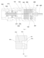
- a driving device including a mounting sleeve 100, a driving shaft 200, and a communication valve 300.
- An accommodating cavity 101 is formed in the mounting sleeve 100 in an axial direction, and the two ends of the mounting sleeve 100 in the axial direction are a driving end 110 and a connecting end 120 respectively.
- the driving shaft 200 extends through the accommodating cavity 101 in the axial direction, and is rotatable around the axis.
- the communication valve 300 is disposed in the accommodating cavity 101.
- An input channel 301, and a cooling channel 302 passing through the communication valve 300 in the axial direction are formed in the communication valve 300.
- An end of the input channel 301 communicates with the cooling channel 302, and the other end of the input channel 301 communicates with the outside to introduce a cooling medium.
- the cooling channel 302 is sleeved on the outside of the driving shaft 200 in a clearance fit.
- a first outlet 302a and a second outlet 302b are respectively formed on a side facing away from the driving end 110 and on a side facing the driving end 110, and are used to output the cooling medium from both ends of the cooling channel 302.
- axial direction in the text description herein refers to an axial direction of the mounting sleeve
- axis refers to an axis of the mounting sleeve
- the driving shaft 200 is connected to an external driving device.
- An end of the driving shaft 200 protruding from the connecting end 120 is connected to a rotational atherectomy catheter and a rotational atherectomy head.
- a supply device for an external injection of cooling medium is connected to the input channel 301. In this way, the rotational atherectomy can be performed.
- the cooling medium physiological saline with different proportions, cooling gas or the like can be selected as required.
- the driving device further includes an output tube 600.
- the output tube 600 is connected to the first outlet 302a and sleeved on the driving shaft 200 in a clearance fit.
- the output tube 600 can deliver the cooling medium to the rotational atherectomy catheter and the rotational atherectomy head at the distal end of the driving shaft 200 to cool down the blood vessels subjected to the rotational atherectomy.
- the clearance fit between the output tube 600 and the driving shaft 200 can restrict the radial movement of the driving shaft 200 and prevent driving shaft 200 from freely swinging in the radial direction, thereby ensuring the normal transmission of the driving force.
- the external supply device is turned on to inject the cooling medium to the rotational atherectomy catheter and the rotational atherectomy head at the end of the driving shaft 200 through the input channel 301, the cooling channel 302, and the output tube 600.
- the rotational atherectomy catheter and the rotational atherectomy head at the end of the driving shaft 200 extend into the inside of the blood vessel of the human body, and then, the driving shaft 200, the rotational atherectomy catheter, and the rotational atherectomy head are driven to rotate by starting the driving device.
- the rotational atherectomy head grinds and ablates coronary artery plaques into fine particles, and the cooling medium can cool down the blood vessels at the rotational atherectomy site and wash away the debris of vascular lesions from the rotational atherectomy.
- the driving shaft 200 since the driving shaft 200 itself has a large length and low rigidity, so that the driving shaft 200 has a certain bending arc.
- the driving shaft 200 may swing in the radial direction, which may cause the driving shaft 200 to contact a wall surface of the cooling channel 302. Since the high-speed rotation speed of the driving shaft 200 in the rotational atherectomy is generally in a range from 6wRPM to 12wRPM, up to about 20wRPM, during the high-speed rotation, the frequent contact between the driving shaft 200 and the wall surface of the cooling channel 302 is capable of generating a lot of heat, which may cause the communication valve 300 to heat up. Therefore, it is necessary to inject the cooling medium into the cooling channel 302.
- the cooling medium entering the cooling channel 302 absorbs heat, and flows out from the first outlet 302a and the second outlet 302b simultaneously, so as to cool down the communication valve 300.
- the cooling medium enters the accommodating cavity 101 after flowing out from the second outlet 302b, and can flow out from a surface of the mounting sleeve 100, or from the driving end 110 or the connecting end 120. In this way, the temperature of the communication valve 300 can be continuously lowered by continuously inputting the cooling medium into the cooling channel 302.
- the heat generated by frequent contact of the high-speed rotating driving shaft 200 with the wall surface of the cooling channel 302 may cause the temperature of the communication valve 300 to rise rapidly and greatly (up to 300°C or higher).
- the communication valve 300 can be deformed and bonded to the driving shaft 200 as one piece, thereby directly hindering and blocking the driving shaft 200 such that the driving shaft 200 cannot rotate normally. In this way, it is possible to avoid the occurrence of damage to the patient's health due to vascular dysfunction caused by the driving shaft performing the rotational atherectomy on the blood vessel in the absence of cooling measures.
- the communication valve 300 can quickly heat up to lock the driving shaft 200, to stop the rotation of the driving shaft 200, thereby preventing the blood vessel from being damaged due to rotational atherectomy in the absence of cooling measures.
- the existence of the pressure difference can facilitate the tendency of the cooling medium to mainly flow out from the first outlet 302a, and then to flow towards the distal end of the driving shaft 200, i.e., into the blood vessel.
- the communication valve 300 is deformed due to temperature rise and bonded to the driving shaft 200 to block the normal operation of the driving shaft 200. It can be understood that in some other embodiments, when the temperature rise is sensed by the outside world (for example, combined with the operator's tactile perception, infrared temperature monitor monitoring, etc.), the operator knows that the cooling is abnormal, and then turns down the driving device immediately. In this way, it can also prevent vascular dysfunction caused by rotational atherectomy applied to blood vessels in the absence of cooling measures, and which is not limited herein.
- the communication valve 300 is made of a material with a heat deformation temperature in a range from 130°C to 270°C.
- the communication valve 300 can be made of a material with a suitable preset heat deformation temperature which may be selected according to actual surgical needs and the specific material of the driving shaft in the driving device.
- the heat deformation temperature of the communication valve 300 is stable and within a reasonable range, the communication valve 300 can be deformed and lock the driving shaft 200 in time when the cooling function fails, so as to prevent the driving device from heating up in time and avoid damage to blood vessels.
- the small increase in temperature of the communication valve 300 will not affect the normal rotation of the driving shaft and the normal use of the driving device.
- the communication valve 300 can be made of materials with different heat deformation temperatures which may be selected within the above range, so as to flexibly meet more usage needs. Furthermore, the communication valve 300 can be made of a material with a heat deformation temperature in a range from 180°C to 220°C, which can further improve the reliability of the communication valve 300 and ensure that the driving shaft 200 is locked within a suitable temperature range.
- the communication valve 300 is made of polyetherimide.
- Polyetherimide is an amber transparent solid with excellent mechanical properties and wear resistance, and with a heat deformation temperature in a range from 198°C to 208°C. Therefore, the communication valve 300 made of polyetherimide can be used for a long time at an operating temperature in a range from -160°C to 180°C. In case of the absence of cooling medium injection, the internal temperature of the communication valve 300 will increase significantly as the friction time increases.
- the deformation or melting of the communication valve 300 can hinder and block the driving shaft 200 such that the driving shaft 200 cannot rotate normally, to avoid severe injury to the patient due to obvious temperature rise caused by performing surgery when an infusion bag is forgotten to be turned on or the cooling medium in the infusion bag is insufficient.
- the polyetherimide since the polyetherimide has a certain tolerance to temperature, the polyetherimide may not melt and cause the driving shaft 200 to be locked when the temperature rises only slightly (for example, rises by 10°C to 50°C). Therefore, the communication valve 300 made of polyetherimide may not affect the normal rotation of the driving shaft and the normal use of the driving device when necessary cooling measures are available, and has good stability and long service life.
- the communication valve 300 When the temperature of the communication valve 300 in this embodiment rises to the heat deformation temperature, the communication valve 300 can be deformed and bonded to the driving shaft 200 as one piece, thereby directly hindering and locking the driving shaft 200 to stop the rotation of the driving shaft 200, thereby preventing the injury to the blood vessels due to continuous rotational atherectomy in the absence of cooling measures, which is safer and can prevent serious medical accidents caused by human errors.
- the communication valve 300 can also be made of other materials with a heat deformation temperature in a range from 130°C to 270°C.
- the communication valve 300 made of such materials can lock the driving shaft 200 in the absence of cooling measures to prevent damage, and may not affect the normal usage of the driving device when the temperature rises slightly with available reasonable cooling measures, and which is no limited herein.
- the cooling channel 302 includes a second cooling channel 3022 and a first cooling channel 3021 that are connected in sequence in a direction from the driving end 110 to the connecting end 120.
- a radial size of the first cooling channel 3021 is greater than a radial size of the second cooling channel 3022, and a radial size of a portion of the first cooling channel 3021 away from the second cooling channel 3022 is greater than a radial size of a portion of the first cooling channel 3021 approaching the second cooling channel 3022.
- the radial size of the first cooling channel 3021 is greater than the radial size of the second cooling channel 3022, the radial size of the first cooling channel 3021 has a tendency to increase in a direction from approaching the second cooling channel 3022 to being away from the second cooling channel 3022. Therefore, the first cooling channel 3021 can form a shape similar to a bell mouth, that is, a gap between the first cooling channel 3021 and the driving shaft 200 gradually increases in this direction, which is beneficial to facilitate the tendency of most of the cooling medium to flow towards the first outlet 302a and be delivered to the rotational atherectomy head at the distal end.
- a difference between the radial size of the second cooling channel 3022 and the radial size of the driving shaft 200 is in a range from 0.15mm to 0.2mm.
- the second cooling channel 3022 may not affect the flow of the cooling medium towards the first cooling channel 3021.
- the gap between the second cooling channel 3022 and the driving shaft 200 is small, which can restrict the radial movement of the driving shaft 200, and prevent the driving shaft 200 from freely swinging in the radial direction, thereby ensuring the normal transmission of the driving force.
- the driving device further includes a guiding cover 400.
- the communication valve 300 and the guiding cover 400 are sequentially arranged in the accommodating cavity 101 in the direction from the driving end 110 to the connecting end 120, and are in sealing contact.
- An outlet channel 401 through which the driving shaft 200 passes is formed in the guiding cover 400.
- a side of the outlet channel 401 facing away from the communication valve 300 is used to be connected to the output tube 600 to output the cooling medium.
- a fixing groove 303 is provided on an end surface of the communication valve 300 facing the guiding cover 400. Inserting a sealing ring into the fixing groove 303 can realize the sealing connection between the guiding cover 400 and the communication valve 300.
- the sealing contact between the guiding cover 400 and the communication valve 300 can prevent the cooling medium from overflowing from between the guiding cover 400 and the communication valve 300.
- the output tube 600 can be directly connected to the outlet channel 401 of the guiding cover 400, so that the output tube 600 can communicate with the cooling channel 302 by using the guiding cover 400.
- the provided guiding cover 400 facilitates the cooperative mounting of the first outlet 302a and the output tube 600.
- a radial size of the outlet channel 401 is less than a maximum radial size of the first cooling channel 3021. Since the radial size of the outlet channel 401 is less than the maximum radial size of the first cooling channel 3021, when the cooling medium enters the smaller-sized outlet channel 401, the flow rate may be significantly increased under the condition of constant quantity of flow, thereby improving the cooling effect on the rotational atherectomy catheter and the rotational atherectomy head at the distal end.
- a side wall of the mounting sleeve 100 defines an introducing hole 102 communicating with the input channel 301 to introduce the cooling medium from the outside.
- the cooling medium in the supply device can flow into the input channel 301 through the introducing hole 102, and then flow into the cooling channel 302 to play a cooling effect.
- the input channel 301 may be connected to external supply device through a structure such as a delivery tube, and which is not specifically limited here.
- a discharge hole 103 is defined on the side wall of the mounting sleeve 100.
- the discharge hole 103 communicates with the accommodating cavity 101 through the second outlet 302b, so as to discharge the cooling medium from the accommodating cavity.
- the cooling medium can flow out from the discharge hole 103 on the side wall of the mounting sleeve 100, thus preventing the cooling medium from accumulating inside the accommodating cavity 101 and ensuring continuous inputting of the cooling medium into the cooling channel 302 to cool down the communication valve 300.
- the accommodating cavity 101 may be directly disposed to extend through the driving device, and the cooling medium flows out directly from the driving end 110 and the connecting end 120.
- the driving device further includes a power component 500.
- the power component 500 is disposed in the accommodating cavity 101 and is closer to the driving end 110 than the communication valve 300.
- the power component 500 is connected to the driving shaft 200 to drive the driving shaft 200 to rotate.
- the power component 500 is integrated in the driving device, that is, the power component 500 and the driving device are designed in one piece, which can save space and simplify the overall structural design.
- the driving shaft 200 can extend out from the driving end 110 and be connected to external power device. Therefore, starting an external power device can also drive the driving shaft 200 to rotate, and which is not limited herein.
- the power component 500 includes a driving rotor 510 and a slewing supporting structure 520.
- the driving rotor 510 is coaxially fixed to the driving shaft 200 to synchronously drive the driving shaft 200 to rotate relative to the mounting sleeve 100.
- the slewing supporting structure 520 is disposed between an outer surface of the driving rotor 510 and an inner surface of the mounting sleeve 100, to provide support for the rotation of the driving rotor 510.
- the rotation of the driving rotor 510 can cause the driving shaft 200 to rotate relative to the mounting sleeve 100, and the slewing supporting structure 520 is disposed between the outer surface of the driving rotor 510 and the inner surface of the mounting sleeve 100, so as to rotatably connected the driving rotor 510 with the mounting sleeve 100.
- the position of the slewing supporting structure 520 is stable, which can provide support for the rotation of the driving rotor 510, and avoid displacement of the driving rotor 510 inside the accommodating cavity during its rotation.
- the driving rotor 510 includes a turbine rotor.
- the side wall of the mounting sleeve 100 defines an air supply channel 104.
- the air supply channel 104 is used to connect the turbine rotor with an external air source to drive the turbine rotor to rotate.
- an external air source is connected to the air supply channel 104.
- the external air source blows high-pressure air to the turbine rotor to drive the turbine rotor to rotate, thereby driving the driving shaft 200 to rotate at a high speed.
- the driving shaft 200 simultaneously drives the rotational atherectomy catheter and the rotational atherectomy head at the distal end to rotate synchronously at a high speed, thereby grinding and ablating coronary artery plaques into fine particles.
- the structure and driving method of the turbine rotor in this embodiment are relatively simple, and high-pressure airflow is used as a power source, which is green and energy-saving and does not generate excessive heat due to operation.
- the slewing supporting structure 520 includes slewing bearings 521 disposed at both ends of the power component 500 in an axial direction.
- An inner ring of the slewing bearing 521 is sleeved on an outer peripheral surface of the driving rotor 510.
- An outer ring of the slewing bearing 521 is fixed on an inner surface of the mounting sleeve 100.
- the slewing bearing 521 can bear large axial and radial loads at the same time, and can provide stable support for the driving rotor 510.
- the slewing bearing 521 is disposed at both ends of the power component 500 in the axial direction, and which can support the drive rotor 510 in a balanced manner.
- the slewing supporting structure 520 further includes a supporting sleeve 522.
- the supporting sleeve 522 is filled between a surface of the outer ring of the slewing bearing 521 and the inner surface of the mounting sleeve 100, to provide support for the slewing bearing 521.
- the supporting sleeve 522 in this embodiment effectively bridges the gap between the outer surface of the slewing bearing 521 and the inner surface of the accommodating cavity 101, and is fixedly connected to the outer surface of the slewing bearing 521 and the inner surface of the mounting sleeve 100 respectively, so that the slewing bearing 521 is firmly connected with the mounting sleeve 100, avoiding the separation of the outer surface of the slewing bearing 521 from the inner surface of the mounting sleeve 100 during the high rotation of the driving shaft 200, thereby avoiding support failure and serious safety accidents.
- the present application further provides a rotational atherectomy device, which includes a rotational atherectomy mechanism and the driving device as described above.
- the connecting end of the driving device is connected to the rotational atherectomy mechanism to drive the rotational atherectomy mechanism.
- the rotational atherectomy mechanism generally includes a rotational atherectomy catheter and a rotational atherectomy head.
- a surface of the rotational atherectomy head is provided with an abrasive layer for grinding lesion plaques in a living body.
- the driving device is detachably connected to the rotational atherectomy mechanism.
- the rotational atherectomy can be performed by connecting the external supply device for injecting the cooling medium to the input channel 301 of the driving device.
- the temperature of the communication valve can quickly rise to the heat deformation temperature, such that the communication valve is deformed and bonded to the driving shaft as one piece, thereby directly hindering and locking the driving shaft such that the driving shaft cannot rotate normally, thereby preventing vascular dysfunction caused by continuous rotational atherectomy applied to blood vessels in the absence of cooling measures, and preventing damage to the patient's health.
- the driving device of the present application is not limited to be connected to the rotational atherectomy mechanism to form the rotational atherectomy device, but can also be connected and cooperated with medical devices with rotation shafts such as suction rotational cutting catheters, dental drills, or orthopedic drills, to form various types of medical devices, and perform different types of medical treatments or plastic surgery.
Landscapes
- Health & Medical Sciences (AREA)
- Life Sciences & Earth Sciences (AREA)
- Surgery (AREA)
- Engineering & Computer Science (AREA)
- Medical Informatics (AREA)
- General Health & Medical Sciences (AREA)
- Biomedical Technology (AREA)
- Heart & Thoracic Surgery (AREA)
- Vascular Medicine (AREA)
- Molecular Biology (AREA)
- Animal Behavior & Ethology (AREA)
- Nuclear Medicine, Radiotherapy & Molecular Imaging (AREA)
- Public Health (AREA)
- Veterinary Medicine (AREA)
- General Engineering & Computer Science (AREA)
- Mechanical Engineering (AREA)
- Surgical Instruments (AREA)
- Dental Tools And Instruments Or Auxiliary Dental Instruments (AREA)
- Mounting Of Bearings Or Others (AREA)
Applications Claiming Priority (2)
| Application Number | Priority Date | Filing Date | Title |
|---|---|---|---|
| CN202011367918.1A CN112145746B (zh) | 2020-11-30 | 2020-11-30 | 驱动装置和旋磨设备 |
| PCT/CN2021/127874 WO2022111221A1 (zh) | 2020-11-30 | 2021-11-01 | 驱动装置和旋磨设备 |
Publications (5)
| Publication Number | Publication Date |
|---|---|
| EP4238516A1 EP4238516A1 (de) | 2023-09-06 |
| EP4238516A9 true EP4238516A9 (de) | 2024-08-21 |
| EP4238516A4 EP4238516A4 (de) | 2024-08-28 |
| EP4238516B1 EP4238516B1 (de) | 2026-02-18 |
| EP4238516C0 EP4238516C0 (de) | 2026-02-18 |
Family
ID=73887203
Family Applications (1)
| Application Number | Title | Priority Date | Filing Date |
|---|---|---|---|
| EP21896722.2A Active EP4238516B1 (de) | 2020-11-30 | 2021-11-01 | Antriebsvorrichtung und rotationsschleifvorrichtung |
Country Status (4)
| Country | Link |
|---|---|
| US (1) | US12551231B2 (de) |
| EP (1) | EP4238516B1 (de) |
| CN (1) | CN112145746B (de) |
| WO (1) | WO2022111221A1 (de) |
Families Citing this family (3)
| Publication number | Priority date | Publication date | Assignee | Title |
|---|---|---|---|---|
| CN112145746B (zh) | 2020-11-30 | 2021-03-23 | 上海微创医疗器械(集团)有限公司 | 驱动装置和旋磨设备 |
| CN114681016A (zh) * | 2020-12-31 | 2022-07-01 | 先健科技(深圳)有限公司 | 减容导管测试系统和测试方法 |
| CN117583949B (zh) * | 2024-01-19 | 2024-05-10 | 山东豪迈数控机床有限公司 | 一种转台及机床 |
Family Cites Families (34)
| Publication number | Priority date | Publication date | Assignee | Title |
|---|---|---|---|---|
| GB1235321A (en) * | 1968-01-30 | 1971-06-09 | Nat Res Dev | Improvements in or relating to drills for clearing obstructions |
| GB1331802A (en) | 1971-05-04 | 1973-09-26 | Goldsmith D J | Thermostatic mixing valve |
| US4146030A (en) | 1976-12-27 | 1979-03-27 | Dynatech Corporation | Cryosurgical instrument |
| US4883458A (en) * | 1987-02-24 | 1989-11-28 | Surgical Systems & Instruments, Inc. | Atherectomy system and method of using the same |
| DE3626684A1 (de) * | 1986-01-20 | 1988-02-11 | Sachse Hans E | Endoskop |
| FR2707154B1 (fr) | 1993-07-08 | 1995-09-15 | Satelec Sa | Bistouri à ultrasons. |
| US5919161A (en) | 1994-05-04 | 1999-07-06 | Devices For Vascular Intervention | Guidewire migration controller |
| US6652546B1 (en) * | 1996-07-26 | 2003-11-25 | Kensey Nash Corporation | System and method of use for revascularizing stenotic bypass grafts and other occluded blood vessels |
| US6818002B2 (en) * | 1999-02-02 | 2004-11-16 | Samuel Shiber | Vessel cleaner and barrier |
| US6979332B2 (en) * | 2003-11-04 | 2005-12-27 | Medtronic, Inc. | Surgical micro-resecting instrument with electrocautery and continuous aspiration features |
| GB2426458A (en) * | 2005-05-26 | 2006-11-29 | Leonid Shturman | Atherectomy device |
| US8551128B2 (en) * | 2007-12-06 | 2013-10-08 | Cardiovascular Systems, Inc. | Rotational atherectomy device with pre-curved drive shaft |
| US8192451B2 (en) | 2008-06-05 | 2012-06-05 | Cardiovascular Systems, Inc. | Cutting and coring atherectomy device and method |
| US8827951B2 (en) * | 2008-07-02 | 2014-09-09 | Doron Besser | Balloon catheter system and methods of use thereof |
| CN102131470A (zh) * | 2008-07-02 | 2011-07-20 | 安乔斯里德公司 | 皱褶的囊导管及其使用方法 |
| US8632557B2 (en) | 2009-05-12 | 2014-01-21 | Cardiovascular Systems, Inc. | Rotational atherectomy device and method to improve abrading efficiency |
| WO2011005795A2 (en) | 2009-07-06 | 2011-01-13 | AUST Development, LLC | Valves and hubs for tubular devices and methods for making and using them |
| US8486096B2 (en) * | 2010-02-11 | 2013-07-16 | Ethicon Endo-Surgery, Inc. | Dual purpose surgical instrument for cutting and coagulating tissue |
| US10952764B2 (en) * | 2010-05-04 | 2021-03-23 | Samuel Shiber | Rotary catheter drive unit containing seal-sets |
| CN201969471U (zh) | 2011-01-26 | 2011-09-14 | 姚镇 | 涡旋式冷热气体分离装置 |
| US9289230B2 (en) * | 2012-09-17 | 2016-03-22 | Cardiovascular Systems, Inc. | Rotational atherectomy device with a system of eccentric abrading heads |
| WO2014106847A1 (en) | 2013-01-07 | 2014-07-10 | Taryag Medical Ltd. | Expandable atherectomy device |
| US10639062B2 (en) | 2016-04-06 | 2020-05-05 | Cardio Flow, Inc. | Atherectomy devices and methods |
| WO2018033920A1 (en) * | 2016-08-18 | 2018-02-22 | Angioslide Ltd. | Drug delivery catheter and method of use thereof |
| CN109715092B (zh) | 2016-09-16 | 2021-07-09 | 泰尔茂株式会社 | 医疗器械 |
| US10945757B2 (en) * | 2016-10-18 | 2021-03-16 | The Regents Of The University Of Michigan | Two-phase technique to restore artery patency and a catheter temperature control system in atherectomy |
| CN107440763B (zh) | 2017-08-16 | 2023-09-12 | 北京赛铂医药科技有限公司 | 一种血管近端保护器 |
| CN209347149U (zh) * | 2017-11-09 | 2019-09-06 | 核工业总医院 | 血管内旋磨支撑系统 |
| WO2019202360A1 (de) | 2018-04-16 | 2019-10-24 | Weh Gmbh Verbindungstechnik | Kupplung und verfahren zum übertragen von fluiden |
| WO2020150591A1 (en) * | 2019-01-18 | 2020-07-23 | Boston Scientific Scimed, Inc. | Gearbox for atherectomy system |
| CN211749912U (zh) * | 2019-08-20 | 2020-10-27 | 上海微创医疗器械(集团)有限公司 | 旋磨装置及医疗器械 |
| CN111012448A (zh) * | 2019-08-20 | 2020-04-17 | 上海微创医疗器械(集团)有限公司 | 旋磨装置 |
| CN211660953U (zh) | 2020-02-23 | 2020-10-13 | 安徽均益金属科技股份有限公司 | 一种闭试水循环冷却主轴机构 |
| CN112145746B (zh) | 2020-11-30 | 2021-03-23 | 上海微创医疗器械(集团)有限公司 | 驱动装置和旋磨设备 |
-
2020
- 2020-11-30 CN CN202011367918.1A patent/CN112145746B/zh active Active
-
2021
- 2021-11-01 EP EP21896722.2A patent/EP4238516B1/de active Active
- 2021-11-01 US US18/255,038 patent/US12551231B2/en active Active
- 2021-11-01 WO PCT/CN2021/127874 patent/WO2022111221A1/zh not_active Ceased
Also Published As
| Publication number | Publication date |
|---|---|
| EP4238516A1 (de) | 2023-09-06 |
| EP4238516B1 (de) | 2026-02-18 |
| US12551231B2 (en) | 2026-02-17 |
| CN112145746A (zh) | 2020-12-29 |
| US20240008892A1 (en) | 2024-01-11 |
| EP4238516A4 (de) | 2024-08-28 |
| CN112145746B (zh) | 2021-03-23 |
| WO2022111221A1 (zh) | 2022-06-02 |
| EP4238516C0 (de) | 2026-02-18 |
Similar Documents
| Publication | Publication Date | Title |
|---|---|---|
| US12551231B2 (en) | Driving device and rotary grinding apparatus | |
| JP7514290B2 (ja) | 血栓溶解と薬剤送達のためのシステムおよび方法 | |
| US12004765B2 (en) | Arthroscopic devices and methods | |
| CN105934205B (zh) | 具有电动机控制的旋开式旋切术装置 | |
| EP3646806B1 (de) | Vorrichtung zur mechanischen thrombusentfernung | |
| US20030055404A1 (en) | Endoscopic rotary abraders | |
| AU2001253173B2 (en) | Intralumenal material removal systems and methods | |
| US10022140B2 (en) | Arthroscopic devices and methods | |
| EP3226784B1 (de) | Drehbare medizinische vorrichtung | |
| US20020165549A1 (en) | Surgical instrument and attachment | |
| EP3957259B1 (de) | Infusionsgeschmierter atherektomiekatheter | |
| US12336731B2 (en) | High speed burr with flex shaft cooling and improved suction | |
| TW202224637A (zh) | 血栓清除裝置 | |
| EP3378418B1 (de) | Integrierte absaugung und kühlung eines winkelgrates | |
| CN211132606U (zh) | 动力源可置于人体内的旋转传动导管 | |
| CN114098903A (zh) | 一种轨道式机械血栓抽吸导管 | |
| EP4494579A1 (de) | Rotablatator | |
| CN115581511B (zh) | 旋磨系统及旋磨组件 | |
| CN111375096A (zh) | 一种冷却系统和导管泵系统 | |
| WO2002087422A2 (en) | Surgical instrument and attachment | |
| EP4289374A1 (de) | Vorrichtungen und systeme zur flüssigkeitsunterstützten chirurgischen gewebebehandlung | |
| EP4427714A1 (de) | In-vivo-temperatursteuerungssystem | |
| US20250169850A1 (en) | Battery powered rotational atherectomy devices | |
| CN120241231A (zh) | 一种电切刀 | |
| HK1226623A1 (en) | Spin-to-open atherectomy device with electric motor control |
Legal Events
| Date | Code | Title | Description |
|---|---|---|---|
| STAA | Information on the status of an ep patent application or granted ep patent |
Free format text: STATUS: THE INTERNATIONAL PUBLICATION HAS BEEN MADE |
|
| PUAI | Public reference made under article 153(3) epc to a published international application that has entered the european phase |
Free format text: ORIGINAL CODE: 0009012 |
|
| STAA | Information on the status of an ep patent application or granted ep patent |
Free format text: STATUS: REQUEST FOR EXAMINATION WAS MADE |
|
| 17P | Request for examination filed |
Effective date: 20230601 |
|
| AK | Designated contracting states |
Kind code of ref document: A1 Designated state(s): AL AT BE BG CH CY CZ DE DK EE ES FI FR GB GR HR HU IE IS IT LI LT LU LV MC MK MT NL NO PL PT RO RS SE SI SK SM TR |
|
| DAV | Request for validation of the european patent (deleted) | ||
| DAX | Request for extension of the european patent (deleted) | ||
| A4 | Supplementary search report drawn up and despatched |
Effective date: 20240731 |
|
| RIC1 | Information provided on ipc code assigned before grant |
Ipc: A61B 17/00 20060101ALN20240725BHEP Ipc: A61B 17/32 20060101ALI20240725BHEP Ipc: A61B 17/3207 20060101AFI20240725BHEP |
|
| GRAP | Despatch of communication of intention to grant a patent |
Free format text: ORIGINAL CODE: EPIDOSNIGR1 |
|
| STAA | Information on the status of an ep patent application or granted ep patent |
Free format text: STATUS: GRANT OF PATENT IS INTENDED |
|
| RIC1 | Information provided on ipc code assigned before grant |
Ipc: A61B 17/3207 20060101AFI20250903BHEP Ipc: A61B 17/32 20060101ALI20250903BHEP Ipc: A61B 17/00 20060101ALN20250903BHEP |
|
| INTG | Intention to grant announced |
Effective date: 20250916 |
|
| GRAS | Grant fee paid |
Free format text: ORIGINAL CODE: EPIDOSNIGR3 |
|
| GRAA | (expected) grant |
Free format text: ORIGINAL CODE: 0009210 |
|
| STAA | Information on the status of an ep patent application or granted ep patent |
Free format text: STATUS: THE PATENT HAS BEEN GRANTED |
|
| AK | Designated contracting states |
Kind code of ref document: B1 Designated state(s): AL AT BE BG CH CY CZ DE DK EE ES FI FR GB GR HR HU IE IS IT LI LT LU LV MC MK MT NL NO PL PT RO RS SE SI SK SM TR |
|
| REG | Reference to a national code |
Ref country code: CH Ref legal event code: F10 Free format text: ST27 STATUS EVENT CODE: U-0-0-F10-F00 (AS PROVIDED BY THE NATIONAL OFFICE) Effective date: 20260218 Ref country code: GB Ref legal event code: FG4D |
|
| REG | Reference to a national code |
Ref country code: DE Ref legal event code: R096 Ref document number: 602021048439 Country of ref document: DE |
|
| REG | Reference to a national code |
Ref country code: IE Ref legal event code: FG4D |
|
| U01 | Request for unitary effect filed |
Effective date: 20260227 |
|
| U07 | Unitary effect registered |
Designated state(s): AT BE BG DE DK EE FI FR IT LT LU LV MT NL PT RO SE SI Effective date: 20260305 |