EP4237625B1 - Offshore-windenergiesystem - Google Patents
Offshore-windenergiesystem Download PDFInfo
- Publication number
- EP4237625B1 EP4237625B1 EP21786123.6A EP21786123A EP4237625B1 EP 4237625 B1 EP4237625 B1 EP 4237625B1 EP 21786123 A EP21786123 A EP 21786123A EP 4237625 B1 EP4237625 B1 EP 4237625B1
- Authority
- EP
- European Patent Office
- Prior art keywords
- cable
- wind energy
- offshore wind
- energy system
- hollow structure
- Prior art date
- Legal status (The legal status is an assumption and is not a legal conclusion. Google has not performed a legal analysis and makes no representation as to the accuracy of the status listed.)
- Active
Links
Images


Classifications
-
- H—ELECTRICITY
- H02—GENERATION; CONVERSION OR DISTRIBUTION OF ELECTRIC POWER
- H02G—INSTALLATION OF ELECTRIC CABLES OR LINES, OR OF COMBINED OPTICAL AND ELECTRIC CABLES OR LINES
- H02G3/00—Installations of electric cables or lines or protective tubing therefor in or on buildings, equivalent structures or vehicles
- H02G3/22—Installations of cables or lines through walls, floors or ceilings, e.g. into buildings
-
- E—FIXED CONSTRUCTIONS
- E02—HYDRAULIC ENGINEERING; FOUNDATIONS; SOIL SHIFTING
- E02B—HYDRAULIC ENGINEERING
- E02B17/00—Artificial islands mounted on piles or like supports, e.g. platforms on raisable legs or offshore constructions; Construction methods therefor
-
- E—FIXED CONSTRUCTIONS
- E02—HYDRAULIC ENGINEERING; FOUNDATIONS; SOIL SHIFTING
- E02B—HYDRAULIC ENGINEERING
- E02B17/00—Artificial islands mounted on piles or like supports, e.g. platforms on raisable legs or offshore constructions; Construction methods therefor
- E02B17/0008—Methods for grouting offshore structures; apparatus therefor
-
- E—FIXED CONSTRUCTIONS
- E02—HYDRAULIC ENGINEERING; FOUNDATIONS; SOIL SHIFTING
- E02D—FOUNDATIONS; EXCAVATIONS; EMBANKMENTS; UNDERGROUND OR UNDERWATER STRUCTURES
- E02D5/00—Bulkheads, piles, or other structural elements specially adapted to foundation engineering
- E02D5/22—Piles
- E02D5/52—Piles composed of separable parts, e.g. telescopic tubes ; Piles composed of segments
- E02D5/523—Piles composed of separable parts, e.g. telescopic tubes ; Piles composed of segments composed of segments
- E02D5/526—Connection means between pile segments
-
- E—FIXED CONSTRUCTIONS
- E04—BUILDING
- E04H—BUILDINGS OR LIKE STRUCTURES FOR PARTICULAR PURPOSES; SWIMMING OR SPLASH BATHS OR POOLS; MASTS; FENCING; TENTS OR CANOPIES, IN GENERAL
- E04H12/00—Towers; Masts or poles; Chimney stacks; Water-towers; Methods of erecting such structures
- E04H12/22—Sockets or holders for poles or posts
- E04H12/2253—Mounting poles or posts to the holder
- E04H12/2269—Mounting poles or posts to the holder in a socket
-
- E—FIXED CONSTRUCTIONS
- E04—BUILDING
- E04H—BUILDINGS OR LIKE STRUCTURES FOR PARTICULAR PURPOSES; SWIMMING OR SPLASH BATHS OR POOLS; MASTS; FENCING; TENTS OR CANOPIES, IN GENERAL
- E04H12/00—Towers; Masts or poles; Chimney stacks; Water-towers; Methods of erecting such structures
- E04H12/22—Sockets or holders for poles or posts
- E04H12/2253—Mounting poles or posts to the holder
- E04H12/2276—Clamping poles or posts on a stub
-
- F—MECHANICAL ENGINEERING; LIGHTING; HEATING; WEAPONS; BLASTING
- F03—MACHINES OR ENGINES FOR LIQUIDS; WIND, SPRING, OR WEIGHT MOTORS; PRODUCING MECHANICAL POWER OR A REACTIVE PROPULSIVE THRUST, NOT OTHERWISE PROVIDED FOR
- F03D—WIND MOTORS
- F03D13/00—Assembly, mounting or commissioning of wind motors; Arrangements specially adapted for transporting wind motor components
- F03D13/20—Arrangements for mounting or supporting wind motors; Masts or towers for wind motors
- F03D13/25—Arrangements for mounting or supporting wind motors; Masts or towers for wind motors specially adapted for offshore installation
-
- F—MECHANICAL ENGINEERING; LIGHTING; HEATING; WEAPONS; BLASTING
- F03—MACHINES OR ENGINES FOR LIQUIDS; WIND, SPRING, OR WEIGHT MOTORS; PRODUCING MECHANICAL POWER OR A REACTIVE PROPULSIVE THRUST, NOT OTHERWISE PROVIDED FOR
- F03D—WIND MOTORS
- F03D9/00—Adaptations of wind motors for special use; Combinations of wind motors with apparatus driven thereby; Wind motors specially adapted for installation in particular locations
- F03D9/20—Wind motors characterised by the driven apparatus
- F03D9/25—Wind motors characterised by the driven apparatus the apparatus being an electrical generator
- F03D9/255—Wind motors characterised by the driven apparatus the apparatus being an electrical generator connected to electrical distribution networks; Arrangements therefor
-
- H—ELECTRICITY
- H02—GENERATION; CONVERSION OR DISTRIBUTION OF ELECTRIC POWER
- H02G—INSTALLATION OF ELECTRIC CABLES OR LINES, OR OF COMBINED OPTICAL AND ELECTRIC CABLES OR LINES
- H02G1/00—Methods or apparatus specially adapted for installing, maintaining, repairing or dismantling electric cables or lines
- H02G1/06—Methods or apparatus specially adapted for installing, maintaining, repairing or dismantling electric cables or lines for laying cables, e.g. laying apparatus on vehicle
- H02G1/10—Methods or apparatus specially adapted for installing, maintaining, repairing or dismantling electric cables or lines for laying cables, e.g. laying apparatus on vehicle in or under water
-
- H—ELECTRICITY
- H02—GENERATION; CONVERSION OR DISTRIBUTION OF ELECTRIC POWER
- H02G—INSTALLATION OF ELECTRIC CABLES OR LINES, OR OF COMBINED OPTICAL AND ELECTRIC CABLES OR LINES
- H02G15/00—Cable fittings
- H02G15/003—Filling materials, e.g. solid or fluid insulation
-
- H—ELECTRICITY
- H02—GENERATION; CONVERSION OR DISTRIBUTION OF ELECTRIC POWER
- H02G—INSTALLATION OF ELECTRIC CABLES OR LINES, OR OF COMBINED OPTICAL AND ELECTRIC CABLES OR LINES
- H02G9/00—Installations of electric cables or lines in or on the ground or water
- H02G9/02—Installations of electric cables or lines in or on the ground or water laid directly in or on the ground, river-bed or sea-bottom; Coverings therefor, e.g. tile
-
- E—FIXED CONSTRUCTIONS
- E02—HYDRAULIC ENGINEERING; FOUNDATIONS; SOIL SHIFTING
- E02B—HYDRAULIC ENGINEERING
- E02B17/00—Artificial islands mounted on piles or like supports, e.g. platforms on raisable legs or offshore constructions; Construction methods therefor
- E02B17/02—Artificial islands mounted on piles or like supports, e.g. platforms on raisable legs or offshore constructions; Construction methods therefor placed by lowering the supporting construction to the bottom, e.g. with subsequent fixing thereto
- E02B17/025—Reinforced concrete structures
-
- E—FIXED CONSTRUCTIONS
- E02—HYDRAULIC ENGINEERING; FOUNDATIONS; SOIL SHIFTING
- E02B—HYDRAULIC ENGINEERING
- E02B17/00—Artificial islands mounted on piles or like supports, e.g. platforms on raisable legs or offshore constructions; Construction methods therefor
- E02B17/02—Artificial islands mounted on piles or like supports, e.g. platforms on raisable legs or offshore constructions; Construction methods therefor placed by lowering the supporting construction to the bottom, e.g. with subsequent fixing thereto
- E02B17/027—Artificial islands mounted on piles or like supports, e.g. platforms on raisable legs or offshore constructions; Construction methods therefor placed by lowering the supporting construction to the bottom, e.g. with subsequent fixing thereto steel structures
-
- E—FIXED CONSTRUCTIONS
- E02—HYDRAULIC ENGINEERING; FOUNDATIONS; SOIL SHIFTING
- E02B—HYDRAULIC ENGINEERING
- E02B17/00—Artificial islands mounted on piles or like supports, e.g. platforms on raisable legs or offshore constructions; Construction methods therefor
- E02B2017/0056—Platforms with supporting legs
- E02B2017/0065—Monopile structures
-
- E—FIXED CONSTRUCTIONS
- E02—HYDRAULIC ENGINEERING; FOUNDATIONS; SOIL SHIFTING
- E02B—HYDRAULIC ENGINEERING
- E02B17/00—Artificial islands mounted on piles or like supports, e.g. platforms on raisable legs or offshore constructions; Construction methods therefor
- E02B2017/0091—Offshore structures for wind turbines
-
- E—FIXED CONSTRUCTIONS
- E02—HYDRAULIC ENGINEERING; FOUNDATIONS; SOIL SHIFTING
- E02B—HYDRAULIC ENGINEERING
- E02B17/00—Artificial islands mounted on piles or like supports, e.g. platforms on raisable legs or offshore constructions; Construction methods therefor
- E02B2017/0095—Connections of subsea risers, piping or wiring with the offshore structure
-
- E—FIXED CONSTRUCTIONS
- E02—HYDRAULIC ENGINEERING; FOUNDATIONS; SOIL SHIFTING
- E02D—FOUNDATIONS; EXCAVATIONS; EMBANKMENTS; UNDERGROUND OR UNDERWATER STRUCTURES
- E02D2250/00—Production methods
- E02D2250/0061—Production methods for working underwater
-
- E—FIXED CONSTRUCTIONS
- E02—HYDRAULIC ENGINEERING; FOUNDATIONS; SOIL SHIFTING
- E02D—FOUNDATIONS; EXCAVATIONS; EMBANKMENTS; UNDERGROUND OR UNDERWATER STRUCTURES
- E02D2300/00—Materials
- E02D2300/0004—Synthetics
- E02D2300/0018—Cement used as binder
- E02D2300/002—Concrete
-
- E—FIXED CONSTRUCTIONS
- E02—HYDRAULIC ENGINEERING; FOUNDATIONS; SOIL SHIFTING
- E02D—FOUNDATIONS; EXCAVATIONS; EMBANKMENTS; UNDERGROUND OR UNDERWATER STRUCTURES
- E02D2300/00—Materials
- E02D2300/0026—Metals
- E02D2300/0029—Steel; Iron
-
- E—FIXED CONSTRUCTIONS
- E02—HYDRAULIC ENGINEERING; FOUNDATIONS; SOIL SHIFTING
- E02D—FOUNDATIONS; EXCAVATIONS; EMBANKMENTS; UNDERGROUND OR UNDERWATER STRUCTURES
- E02D2600/00—Miscellaneous
- E02D2600/20—Miscellaneous comprising details of connection between elements
-
- E—FIXED CONSTRUCTIONS
- E02—HYDRAULIC ENGINEERING; FOUNDATIONS; SOIL SHIFTING
- E02D—FOUNDATIONS; EXCAVATIONS; EMBANKMENTS; UNDERGROUND OR UNDERWATER STRUCTURES
- E02D27/00—Foundations as substructures
- E02D27/32—Foundations for special purposes
- E02D27/42—Foundations for poles, masts or chimneys
- E02D27/425—Foundations for poles, masts or chimneys specially adapted for wind motors masts
-
- E—FIXED CONSTRUCTIONS
- E02—HYDRAULIC ENGINEERING; FOUNDATIONS; SOIL SHIFTING
- E02D—FOUNDATIONS; EXCAVATIONS; EMBANKMENTS; UNDERGROUND OR UNDERWATER STRUCTURES
- E02D27/00—Foundations as substructures
- E02D27/32—Foundations for special purposes
- E02D27/52—Submerged foundations, i.e. submerged in open water
- E02D27/525—Submerged foundations, i.e. submerged in open water using elements penetrating the underwater ground
-
- Y—GENERAL TAGGING OF NEW TECHNOLOGICAL DEVELOPMENTS; GENERAL TAGGING OF CROSS-SECTIONAL TECHNOLOGIES SPANNING OVER SEVERAL SECTIONS OF THE IPC; TECHNICAL SUBJECTS COVERED BY FORMER USPC CROSS-REFERENCE ART COLLECTIONS [XRACs] AND DIGESTS
- Y02—TECHNOLOGIES OR APPLICATIONS FOR MITIGATION OR ADAPTATION AGAINST CLIMATE CHANGE
- Y02E—REDUCTION OF GREENHOUSE GAS [GHG] EMISSIONS, RELATED TO ENERGY GENERATION, TRANSMISSION OR DISTRIBUTION
- Y02E10/00—Energy generation through renewable energy sources
- Y02E10/70—Wind energy
- Y02E10/72—Wind turbines with rotation axis in wind direction
-
- Y—GENERAL TAGGING OF NEW TECHNOLOGICAL DEVELOPMENTS; GENERAL TAGGING OF CROSS-SECTIONAL TECHNOLOGIES SPANNING OVER SEVERAL SECTIONS OF THE IPC; TECHNICAL SUBJECTS COVERED BY FORMER USPC CROSS-REFERENCE ART COLLECTIONS [XRACs] AND DIGESTS
- Y02—TECHNOLOGIES OR APPLICATIONS FOR MITIGATION OR ADAPTATION AGAINST CLIMATE CHANGE
- Y02E—REDUCTION OF GREENHOUSE GAS [GHG] EMISSIONS, RELATED TO ENERGY GENERATION, TRANSMISSION OR DISTRIBUTION
- Y02E10/00—Energy generation through renewable energy sources
- Y02E10/70—Wind energy
- Y02E10/727—Offshore wind turbines
Definitions
- the invention relates to an offshore wind energy system.
- Offshore structures are increasingly being built, especially at sea.
- offshore wind farms with a large number of offshore wind energy structures are being installed to generate electrical energy or to provide electrical energy from so-called renewable energy sources.
- Offshore locations are usually characterized by relatively consistent wind conditions and high average wind speeds, so that so-called offshore wind farms are increasingly being built.
- An offshore wind farm usually has a large number of offshore wind energy structures, such as a large number of offshore wind turbines, measurement masts and/or at least one offshore substation.
- the offshore wind farm can be electrically connected via the offshore substation, for example, to an onshore substation or another offshore substation or offshore converter station.
- An onshore substation can in turn be connected to a public power grid.
- An offshore wind turbine is designed to convert kinetic wind energy into electrical energy.
- energy cables in the form of Submarine cables are laid.
- a submarine cable can be electrically connected to a generator of an offshore wind turbine.
- an offshore structure directly (also called foundation) on or in the underwater ground, in particular a seabed, by means of a foundation (e.g. monopile, tripod, triple or jacket foundations).
- a foundation e.g. monopile, tripod, triple or jacket foundations.
- a foundation has at least one tower-shaped, in particular cylindrical, hollow structural element (also called a tower-shaped foundation structure).
- a hollow structural element usually has a circumferential wall extending in the longitudinal direction, whereby the (foundation) wall can be limited on the underside by a lower end face and on the top by an upper end face.
- J-tubes It is known from the state of the art for offshore structures to route a submarine cable connected to an offshore facility of the offshore structure through so-called J-tubes to the underwater bottom surface (in particular a seabed surface).
- J-tubes can cause additional wave loads. They can also be damaged by a ship impact and must also be regularly cleared of growth.
- a submarine cable through the interior or cavity of at least one Hollow structural element (in particular freely suspended) to be led downwards from the offshore installation.
- a cable duct or cable recess is provided in the wall of the hollow structural element through which the submarine cable is led from the interior to the outside to the underwater bottom surface.
- the removal of the submarine cable represents a major challenge. If, for example, two hollow structure elements are plugged together near the underwater floor surface and an annular space between the inner surface of the second hollow structure element and the outer surface of the first hollow structure element is grouted and/or a so-called slip joint is created between the hollow structure elements, the removal of a submarine cable from the interior is complex and time-consuming.
- the annular space between the hollow structure elements is regularly grouted.
- a special sealing of the cable ducts against the grout material is required. required. This seal must not be damaged when installing the hollow structure elements. This increases the cost of installation even further.
- a solution to the problem described above would be to lead the submarine cable out of the interior above the overlap area or the annular space area. However, this is not considered feasible with the current technology. In particular, at the large distances to the underwater floor surface of more than 5 m, the submarine cable is exposed to the strong current forces on this stretch without protection. This would result in excessive stress on the submarine cable, which cannot be compensated for with the cable protection systems available on the market.
- Offshore wind energy systems of this type with at least one cable routing arrangement on a hollow structural element are EP3696326A1 , WO2020/074421A1 , WO2020/157196A1 and from CN104934920A known. Therefore, the invention is based on the object of providing an offshore wind energy system in which the disadvantages described above are at least reduced and in particular a routing of the submarine cable from a foundation to an underwater bottom surface is possible in a simpler and less complex manner.
- an offshore wind energy system provided with a cable routing arrangement which submarine cable exiting through a cable duct to
- the disadvantages of the state of the art are at least reduced.
- the submarine cable can be routed from a foundation to an underwater ground surface in a simpler and less complex manner.
- the cable routing arrangement reduces the load on the submarine cable due to flow forces that can act on the submarine cable. This makes it possible to lead the submarine cable out of the foundation at a height of more than 5 m above the underwater seabed surface (in an initial installation state of the foundation).
- An offshore wind energy system comprises at least one foundation and at least one cable routing arrangement.
- a foundation is in particular part of an offshore structure and preferably serves to support at least one offshore facility of the offshore structure.
- An offshore structure is preferably an offshore wind energy structure, such as an offshore wind turbine, an offshore measurement mast or an offshore substation.
- it is an offshore structure to which at least one submarine cable is connected.
- the submarine cable can be connected to the offshore facility of the offshore structure.
- An offshore structure can also be a drilling or production platform or another offshore platform, preferably set up for the extraction, conversion and/or storage of energy, such as an offshore plant for the production of hydrogen (provided a submarine cable is connected to the offshore structure).
- an offshore structure may comprise an offshore installation which may be fixed by its foundation in an underwater bed, in particular a seabed.
- An offshore structure may in particular be fixed by the Offshore installation (e.g. a platform, a nacelle, tower, generator, rotor, transformer and/or the like) and at least one foundation must be formed.
- the foundation comprises a first hollow structural element or a first tower-shaped foundation structure.
- a hollow structural element is preferably cylindrical.
- a cylindrical hollow structural element can in particular be a hollow pile.
- the first hollow structure element has a circumferential first wall extending in the longitudinal direction (i.e. along the longitudinal axis of the hollow structure element).
- a hollow structure element can have a circular cross-sectional area.
- a different cross-sectional area can also be provided, such as an oval one.
- a wall of a hollow structure element can have two distal ends, each of which is delimited by opposing end faces.
- a first end face can be an upper end face and a second end face can be a lower end face.
- the upper and lower sides can be defined by the position of the hollow structure element in the final installation state. In the installation state, the lower end face is arranged in the direction of the underwater floor.
- the upper end face can in particular protrude at least from the underwater floor in the direction of the water surface.
- a cable feedthrough or recess for a submarine cable is arranged in the first wall, which breaks through the first wall.
- a cable feedthrough is in particular formed in such a way that a submarine cable can be guided outwards from the interior of the first hollow structure element.
- the submarine cable can be arranged (freely) hanging in a cavity or interior formed by the first wall and can be guided outwards from the cavity through the cable feedthrough.
- the offshore facility in an offshore wind turbine, not only the foundation but also the offshore facility can be assembled in an assembled state, comprising a tower with a nacelle including a turbine and wind wheel. From the generator, which is located in the nacelle, the submarine cable can run through the tower and the first hollow structure element to the cable duct and be led out of the foundation there.
- a cable guide arrangement is arranged on the outer surface or outside of the first wall of the first hollow structure element.
- An arrangement on the outer surface means in particular that the cable guide arrangement is arranged outside the foundation.
- an arrangement on the outer surface comprises a radial spacing of the cable guide arrangement from the outer surface of the foundation.
- the cable guide arrangement extends in a radial direction starting from the first hollow structure element.
- the cable guide arrangement can be aligned with the cable feedthrough.
- the cable guide arrangement is a separate arrangement and can in particular be arranged on the underwater floor surface, for example be attached to the underwater floor.
- the cable guide arrangement and its at least one element does not directly touch the outer surface of the first hollow structure element and is arranged at a radial distance between 0.25 m and 3 m from the outer surface, preferably at a radial distance of up to 5 m.
- the cable guide arrangement is designed in such a way that the emerging submarine cable is guided in a radial direction from the cable feedthrough to an underwater floor surface of the underwater floor. Guiding the submarine cable in this case means in particular that the freedom of movement of the submarine cable in the horizontal and/or vertical direction is at least restricted by the cable guide arrangement. This allows the forces exerted on the submarine cable by a current and thus the load on the submarine cable to be reduced.
- two or more cable feedthroughs may be provided, for example for a corresponding number of submarine cables. It is also understood that a corresponding number of cable routing arrangements may be provided.
- the cable feedthrough of the first hollow structure element can be located at least 5 m above the underwater ground surface in an installation state of the foundation, in particular 6 m, particularly preferably between 8 m and 12 m.
- the distance between the underwater ground surface and in particular the lower edge of the cable feedthrough can be greater than 5 m, preferably greater than 6 m and particularly preferably between 8 m and 12 m.
- the underwater bottom surface is defined here in particular as the vertical plane which is specified in the planning documents of the offshore structure (in particular of an offshore wind farm) as the water depth below the reference plane LAT (lowest astronomical tide). It is understood that the water depth and thus the distance to the cable feedthrough can change after installation of the offshore structure, for example due to the removal or accumulation of sediments and/or the addition of a scour protection layer.
- the submarine cable can be safely led out of the first hollow structure element even at the heights mentioned. This makes it possible to carry out sealing measures and/or grouting in the area between 0 m and 5 m, preferably 8 m, without this making the process of leading out the submarine cable complex and expensive.
- the foundation can comprise a second hollow structure element.
- the second hollow structure element can have an overlap section that protrudes (on the outside or inside) over an end section (also called overlap section) of the first hollow structure element, and an integration section that can be integrated at least partially into an underwater floor.
- the cable feedthrough of the first hollow structure element can be arranged (in an installation state of the foundation) at least above the overlap section (i.e. above the upper end of the second hollow structure element).
- the first hollow structure element and the second hollow structure element can be inserted into one another in the overlap section.
- two concentric and nested pipes can be designed as the foundation.
- the first hollow structure element can have an outer diameter that is congruent to an inner diameter of the second hollow structure element.
- the first hollow structure element can have an inner diameter that is congruent to an outer diameter of the second hollow structure element.
- the first hollow structure element can also be referred to as a so-called transition piece and the second hollow structure element as a tie-in element.
- the Embedment element with a specific embedment depth or embedment length (e.g. between 7 and 20 m) embedded or founded in the underwater soil.
- the second hollow structure element comprises in particular a circumferential second wall extending in the longitudinal direction.
- no cable feedthrough is arranged in the second wall.
- the first hollow structure element has in particular a transition section which protrudes from the front side of the second hollow structure element.
- a (first and/or second) hollow structure element can preferably be formed monolithically and tubularly and extend in a longitudinal direction. This longitudinal direction of the first hollow structure element is preferably collinear with the longitudinal direction of the second hollow structure element in the installed state.
- the transition piece may have at least one ship landing facility with ladder.
- the advantage of a foundation formed from two hollow structural elements that can be assembled at the installation site is that the weight of a hollow structural element to be transported, in particular a pile, can be significantly reduced.
- the first hollow structure element can be connected to the second hollow structure element by means of a grout connection or by means of a slip joint method.
- a (circumferential) annular space can be provided in the region of the overlap section of the second hollow structure element.
- a seal resting on the lateral surfaces can be arranged all around the hollow structure element.
- a seal resting on the lateral surfaces can be arranged all around the hollow structure element in an annular space between the outer lateral surface of the second hollow structure element and the inner lateral surface of the first hollow structure element.
- the seal in the longitudinal direction of the first hollow structure element, the seal can be arranged below the cable feedthrough.
- an annular space between the inner surface of the second hollow structure element and the outer surface of the first hollow structure element can be at least partially grouted.
- an annular space between the outer surface of the second hollow structure element and the inner surface of the first hollow structure element can be at least partially grouted.
- An upper edge of the grout connection can be arranged in the longitudinal direction of the foundation at least below a lower edge of the cable feedthrough. The grout connection can be produced in such a way that it is completely below the cable feedthroughs in the overlap area. In this case, the seal can preferably be omitted.
- the seal can preferably be expandable, such that the volume of the seal can be increased after the assembly of the hollow structure elements, in particular that the seal is pneumatically or hydraulically loaded with a filling material.
- the annular space can be relatively narrow, in particular if a slip-joint connection is produced rather than a grout connection.
- the seal can be expandable.
- the seal is shaped so that its volume can be increased after the assembly of the hollow structure elements.
- the seal can be pumped up, for example, either pneumatically or hydraulically, by filling it with a filling material.
- a volume can be kept as a hollow space inside the seal. After assembly, this volume can be filled with the filling material under pressure so that the seal closes the annular gap between the hollow structure element and the transition piece in the area of the cable ducts.
- the seal can contain swellable (e.g. clay-containing) material, which swells when it comes into contact with water.
- insertion aids arranged on an upper front edge of the second hollow structure element can interact with insertion aids arranged on a lower front edge of the first hollow structure element in such a way that a relative alignment of the azimuth angles of the hollow structure elements to one another is defined.
- the insertion aids can be interlocking projections and recesses that project radially inwards and radially outwards. This can simplify the assembly of the first and second hollow structure elements.
- At least one stop pointing radially inwards can be formed on the inner surface of the wall in a connection section of the second hollow structure element.
- at least one stop pointing radially outwards can be formed on the outer surface of the wall in a connection section of the second hollow structure element.
- a wall of a hollow structural element can be made of metal, in particular steel.
- a (first and/or second) wall of a (first and/or second) hollow structural element can be made of a mineral building material.
- the mineral building material can contain cement at least in part.
- the mineral building material is preferably concrete, which consists of cement, gravel, Sand and water are mixed and have hardened, especially after pouring.
- the water-cement ratio (w/c) of the mineral building material can be less than 0.45, in particular less than 0.35 and particularly preferably less than 0.3.
- the moments and shear forces that occur in particular in wind turbines can be adequately absorbed by the hollow structure element, in particular if the building material has a strength class of at least C40/50, preferably C70/85, in particular C100/115 according to EN 206 and EN1992.
- Sufficient long-term stability of the foundation over the service life of an offshore structure, in particular an offshore wind turbine, especially in the case of permanent penetration by water, can be achieved in particular by the mineral building material having a pore content (air pores) of less than 5%, preferably less than 3%, in particular less than 2%.
- the total porosity measured using mercury pressure porosity should be P 28d ⁇ 12 vol-% after 28 days and P 90d ⁇ 10 vol-% after 90 days.
- the mineral building material has a porosity of P 28d ⁇ 12 vol-% in a mercury pressure porosimetric measurement, as already described.
- P 28d is a measurement over 28 days.
- the porosity is preferably also less than 10 vol-%.
- the porosity is preferably ⁇ 10 vol-%, in particular ⁇ 8 vol-%.
- a sufficient load-bearing capacity of the foundation can be achieved in particular by the mineral building material having a cement content of at least 350 kg/m 3 , preferably at least 450 kg/m 3 , particularly preferably at least 650 kg/m 3 .
- a wall can be mechanically prestressed.
- the prestressing can suppress cracks and thus keep the surfaces largely free of tensile stress, which is particularly advantageous in the case of fluctuating torque loads.
- the prestressing force is preferably 5%, in particular more than 15%, greater than the compressive strength of the foundation wall.
- the prestressing force is preferably applied in the longitudinal direction.
- the mineral building material can be (metallically) reinforced.
- the metallic reinforcement is in particular a steel reinforcement.
- the reinforcement can be provided by fibers or reinforcing iron. Fiber reinforcement can also be achieved by carbon fiber, glass fiber or metal fiber.
- the reinforcement can be formed in such a way that it has at least 26 mm, preferably at least 40 mm, concrete cover at 90% of the measuring points, preferably at 98% of the measuring points.
- the mineral building material can be reinforced with ferritic stainless steel reinforcing steel.
- the reinforcement cannot have a chromium content of more than 18 M%.
- the reinforcement can contain molybdenum components.
- the mineral building material can be reinforced with austenitic stainless steel reinforcing steel.
- the reinforcement can contain at least 5 M%, in particular between 5 M% and 14 M% nickel and/or between 12 M% and 22 M%, in particular 15 M% and 20 M% chromium.
- the mineral building material can be reinforced with ferritic-austenitic stainless steel reinforcing steel.
- the reinforcement can contain at least 18 M%, in particular between 15 M% - 20 M% chromium and 2 M% - 8 M% nickel and optionally molybdenum.
- the mineral building material can be sealed, in particular with a sealing film.
- a sealing film can be, for example, an aluminum-butyl sealing film.
- the cable guide arrangement can comprise at least one (cable) support element, designed at least for vertical support of the submarine cable.
- at least one support element with a vertical support function, which supports the submarine cable at least in a vertical direction, a significant reduction in the load on the submarine cable can be achieved.
- Vertical support means in particular that the freedom of movement of the submarine cable is restricted downwards and/or upwards.
- a height (in relation to the underwater ground surface) of the at least one support element can be reduced in a step-like or continuous manner in the radial direction (starting from the outer surface).
- at least one wedge-shaped or ramp-shaped support element can be provided which extends in a radial direction.
- the height of the wedge-shaped or ramp-shaped support element can preferably be reduced continuously.
- a lower surface (in particular a foot section) of the wedge-shaped or ramp-shaped support element can be substantially horizontal and the upper surface (in particular a head section) can be an inclined surface.
- the lower surface can contact the underwater ground surface in an installation state or even be embedded in the underwater ground.
- the upper surface can carry the submarine cable and support it at least in a vertical direction.
- a plurality of individual support elements (for example in the form of a plurality of drop lances) can be provided, wherein the majority of the support elements of a cable guide arrangement extend in a radial direction.
- the height of the support elements arranged in the radial direction can be reduced gradually or in steps, i.e. from support element to support element.
- the height means in particular the distance between the part of the at least one support element that contacts the submarine cable (for example the upper surface) and the underwater bottom surface (assuming an almost flat underwater bottom surface over the entire radial extension direction of the cable guide arrangement).
- the at least one support element can be made of any material and have any shape, as long as it is ensured that the at least one support element guides the submarine cable from the cable feedthrough to the underwater floor surface with at least vertical support.
- the at least one support element can be formed by bulk material.
- the bulk material can be piled up on an outer wall in the shape of a ramp.
- the submarine cable can then be laid on the bulk material and guided through the formed upper surface of the bulk material support element.
- the bulk material can in particular have a sufficiently large (average) grain size, which in particular prevents scouring of the submarine cable and/or erosion of the bulk material support element as a result of the prevailing ocean current.
- the average grain size can be between 1 mm and 5000 mm.
- the average grain size can be between at least 200 mm and 5000 mm, more preferably between at least 1000 mm and 5000 mm.
- the at least one support element can be a prefabricated concrete component.
- the prefabricated concrete component can be prefabricated, in particular from a previously described mineral building material.
- the at least one prefabricated concrete component can then be arranged next to the foundation (aligned with the cable feedthrough), in particular lowered. A simple installation of the offshore wind energy system is possible.
- a wedge- or ramp-shaped support element as described above can be a single (one-piece) precast concrete component.
- a support element can also be formed from a plurality of precast concrete components.
- the at least one support element can also be a prefabricated metal component, such as a prefabricated steel component.
- the at least one support element can be a cable tensioning arrangement that can be anchored to the underwater seabed.
- a plurality of anchorable cable tensioning arrangements can be arranged one behind the other in a radial direction as a cable guide arrangement.
- a cable or a chain of a cable tensioning arrangement can be positioned above the submarine cable to be guided.
- the ends of the cable or chain can be anchored in the underwater seabed (for example by suitable anchors), in particular such that the cable or chain is tensioned above the submarine cable.
- the tensioning can exert a force on the submarine cable that acts at least in the vertical direction (in particular in the direction of the underwater seabed surface). This can support the submarine cable at least in the vertical direction.
- Cable fixing modules (for example sleeves) can be arranged on the submarine cable in order to fix the cable or chain to the submarine cable.
- a plurality of cable tensioning arrangements can be arranged, whereby the length of the cable or chain, starting from the outer surface of the first wall, can be reduced in the radial direction (in an anchored and in particular tensioned state).
- the length is in particular the length between the two anchors (assuming that all anchors are buried to the same depth).
- the at least one support element can have a cable holder for guiding the submarine cable.
- the shape of the cable holder can correspond in particular to the (external) shape of the submarine cable.
- the cable receptacle can be a channel-like depression running in a radial direction in an upper surface of the at least one support element.
- each support element can preferably have such a depression.
- the support elements can be set up in such a way that the respective depressions are aligned with one another.
- an (inner) diameter of the recess may be at least larger than an outer diameter of the submarine cable.
- the channel-like recess can form a 3 ⁇ 4 circle (cross-sectional view) with a cable opening, either as a continuous slot opening upwards or with an opening arranged at the end remote from the hollow structural element with a width which is larger than the cable diameter, preferably cable diameter plus 5 mm, particularly preferably cable diameter plus 20 mm.
- the cable guide arrangement can comprise at least one cable fixing module.
- the at least one cable fixing module can be designed to fix the submarine cable to the cable guide arrangement.
- the at least one cable fixing module can interact with the at least one support element in such a way that the submarine cable is fixed to the support element, in particular its freedom of movement is further restricted.
- the at least one cable fixing module can be a clip mechanism (in particular at least one clamp).
- a clip mechanism in particular enables the submarine cable to be clamped to the at least one support element.
- a clip mechanism is in particular easy to install.
- the at least one cable fixing module can be a filling material, in particular a cable cement (e.g. CableCem ® ).
- a filling material in particular a cable cement
- the submarine cable can be securely fixed.
- Another advantage of a filling material, in particular a cable cement is its good thermal conductivity. The low thermal resistance of a cable cement ensures excellent heat dissipation and thus lower energy loss in the cable harness.
- a filling material e.g. made of grey cast iron
- a bulk material support element can be used for a bulk material support element to ensure secure fixation of the submarine cable.
- a further aspect of the invention is an offshore structure, in particular an offshore wind energy structure.
- the offshore structure is according to claim 14.
- z denotes the vertical axis or direction and r the radial direction.
- the terms “bottom”, “lower” etc. and “top”, “upper” etc. refer in particular to the vertical axis z and in particular to the installation state of the foundation or offshore structure.
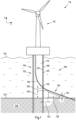
- the Figure 1 shows a schematic view of an embodiment of an offshore structure 114 with an embodiment of an offshore wind energy system 100 according to the present invention.
- An offshore wind energy structure 114 in the form of an offshore wind turbine 114 is shown as an example of an offshore structure 114.
- the offshore structure 114 and thus a foundation 102 of the offshore structure 114 are shown in an installed state.
- the following explanations can be easily transferred to other offshore structures.
- the offshore structure 114 comprises at least one offshore wind energy system 100 and at least one offshore facility 116 (in this case, e.g., tower, rotor, generator, etc.).
- a submarine cable 118 is connected to the offshore facility 116 in order to transport the generated electrical energy or the generated electrical current to another entity.
- a submarine cable 118 is in particular an energy cable, in particular a medium-voltage cable 118 with a power capacity between 3 MW and 70 MW, preferably between 9 MW and 60 MW, or a high-voltage cable 118 with a power capacity between 70 MW and 2.5 GW, preferably between 360 MW and 1500 MW.
- the offshore wind energy system 100 includes a foundation 102 and a cable routing arrangement 104 disposed adjacent to the foundation 102.
- the foundation 102 comprises a first hollow structure element 106 or a first tower-shaped foundation structure 106.
- the first hollow structure element 106 comprises a circumferential first wall 105 extending in the longitudinal direction (i.e. along the longitudinal axis of the hollow structure element 106).
- the first wall 105 is delimited at the lower end of the first hollow structure element 106 by a lower end face. At the upper end of the first hollow structure element 106, the first wall is delimited by an upper end face.
- the first hollow structure element 106 has a circular cross-sectional area. In other variants, a different cross-sectional shape can also be provided, such as an elliptical or oval one.
- the first hollow structure element 106 can be formed as a hollow pile 106 with an interior space 112. The submarine cable 118 can be guided downwards through the interior space 112, in particular can be arranged freely hanging in the interior space 112.
- the first wall 105 has an inner surface 110 or inner wall 110 and an outer surface 108 or outer wall 108.
- the inner side 110 faces towards the interior 112, while the outer surface 108 faces outwards.
- a wall is particularly limited by an inner wall and an outer wall or by an inner diameter and an outer diameter.
- the wall is particularly the outer boundary of a hollow structural element.
- the Figure 1 the foundation 102 in an installation state in which a binding end of the at least one hollow structure element 106 in the underwater floor 120 (reference numeral 122 refers to the underwater soil surface), i.e. is embedded in the underwater soil 120 with a certain depth or embedment length (eg between 7 m and 20 m).
- the first hollow structure element 106 protrudes above the water surface 124.
- the first wall 105 is preferably made of concrete (as previously described), in particular cast concrete.
- the wall thickness in the longitudinal direction (z) remains constant or unchanged over the entire length of the first hollow structure element 106.
- the wall thickness of a hollow structure element can also change.
- the wall thickness can taper from the upper end face to the lower end face, for example by the inner diameter increasing and the outer diameter remaining constant or the outer diameter reducing and the inner diameter remaining constant.
- a cable duct 126 is arranged in the first wall 105, breaking through the first wall 105.
- the submarine cable 118 can exit to the outside through the cable duct 126.
- the offshore wind energy system 100 comprises at least one cable guide arrangement 104 extending in the radial direction r (and in the installed state, horizontal direction) and arranged on the outer surface 108 of the first wall 105 of the first hollow structure element 106, configured to guide the submarine cable 118 emerging from the cable feedthrough 126 from the cable feedthrough 126 to an underwater floor surface 122 of the underwater floor 120.
- the cable guide arrangement 104 in the present case comprises a support element 138.
- the support element 138 which is here formed in the shape of a ramp, is in particular designed for the vertical support of the submarine cable 118, i.e. for limiting the freedom of movement of the submarine cable 118 at least in the vertical direction, e.g.
- the exited or led out submarine cable 118 is guided through the upper (inclined) surface of the support element 138 from the cable feedthrough 126 to an underwater bottom surface 122 of the underwater bottom 120 and supported downwards.
- the at least one support element 138 can be radially spaced from the outer surface 108.
- a support element preferably (in principle) contacts neither the first nor the second hollow structure element.
- the radial distance 132 between the outer surface 108 and the end of the support element 138 facing the outer surface can be, for example, between 0.2 m and 4 m, preferably between 0.5 m and 2 m.
- the upper end of the support element 138 is preferably vertically spaced from the lower edge of the cable duct 126.
- the vertical distance 130 between the lower edge of the cable duct 126 and the upper end (or the highest vertical point) of the support element 138 can be between 0.5 m and 2 m.
- the dimensioning of the distances 130, 132 depends in particular on the permissible bending radius of the submarine cable 118.
- the maximum height 134 of the support element 138 and/or the slope of the ramp of the support element 138 can also depend on the bending radius of the submarine cable 118.
- the end of the support element 138 facing away from the outer wall 108 has a vertical height 136 that can be between 0 m and 7.5 m.
- the cable feedthrough 126 of the first hollow structure element 106 is located at least 5 m above the underwater floor surface 122, in particular 6 m, particularly preferably between 8 m and 12 m.
- the vertical distance between the underwater floor surface 122 and the cable feedthrough 126, in particular the lower edge of the cable feedthrough 126 can be more than 5 m, preferably more than 6 m, particularly preferably between 8 m and 12 m.
- the height of the at least one support element 238 decreases continuously in the radial direction from the end of the support element 238 facing the outer surface 108 to the end of the support element 238 pointing away from the outer surface 108.
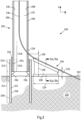
- FIGS. 2 to 2b show schematic views of a further embodiment of an offshore wind energy system 200 for an offshore structure. To avoid repetition, only the differences from the previous embodiment are described below and otherwise reference is made to the explanations for Figure 1 referred to.
- the foundation 202 comprises a first hollow structure element 206 and a second hollow structure element 240.
- the first (in particular cylindrical) hollow structure element 206 can also be referred to as transition piece 206 and the second (in particular cylindrical) hollow structure element 240 as binding element 240.
- the second hollow structure element 240 comprises an overlap section 242 and an integration section 244.
- the integration section 244 is at least partially integrated into the underwater floor 220.
- the overlap section 242 of the second hollow structure element 240 overlaps with an end section 246 or further overlap section 246 of the first hollow structure element 206 (in an overlap region of the foundation).
- the first hollow structure element 206 is inserted into the second hollow structure element 240.
- the underside end face of the first hollow structure element 206 rests on at least one (circumferential) and radially inwardly projecting stop 256.
- the at least one stop 256 can, for example, be fastened, for example welded, to an inner side 250 of a second (circumferential and extending in a longitudinal direction z) wall 251.
- annular space 252 is formed between the inner surface 250 of the second hollow structure element 240 and the outer surface 208 of the first hollow structure element 206.
- the annular space 252 is filled, in particular grouted, with filling material 254, in particular a grout (mortar).
- the filling material 254 is introduced into the annular space 252 after the first hollow structure element 206 has been inserted into the hollow structure element 240.
- the transition section 248 adjoins the end section 246 or overlap section 246.
- the transition piece 206 protrudes in particular from the second hollow structure element 240 with the transition section 248.
- an (expandable) seal can alternatively or additionally be arranged in the annular space.
- at least one insertion aid, alignment aid or the like can be provided for aligning the hollow structure elements with one another.
- the offshore wind energy system 200 comprises a cable guide arrangement 204 with a (single) ramp-shaped support element 238.
- the support element 238 can preferably be a precast concrete component 238.
- a sectional view of a first embodiment of the cable guide arrangement 204 is shown in Figure 2a and another embodiment of the cable guide arrangement 204 is shown in Figure 2b shown.
- the support element 238, which is in particular formed in one piece, can comprise a foot section 233, a head section 235 with an upper surface 237 and a connecting section 231 connecting the foot section 233 and the head section 235.
- the support element 238 can in particular be placed on the underwater bottom surface 222 by means of the foot section 233.
- a cable receptacle 260 for guiding the submarine cable 218 can be provided in the support element 238, in particular in the head section 235.
- the shape of the cable receptacle 260 corresponds in particular to the shape of the submarine cable 218.
- the illustrated support element 238 supports the submarine cable 218 at least in a vertical direction.
- at least the freedom of movement downwards is limited by the at least one support element 238.
- the cable receptacle 260 is in the present case a channel-like recess 260 extending in a radial direction r (preferably along the entire length 229 of the support element 238) which is formed in the upper surface 237 of the support element 238.
- the diameter 262 of the recess 260 can be at least larger than an outer diameter 264 of the submarine cable 218.
- the diameter 262 of the recess 260 is smaller and corresponds almost to the outer diameter 264 of the submarine cable 218.
- the recess 260 in a cross-sectional view in the embodiment according to Figure 2b the shape of a 3 ⁇ 4 circle, while in the Figure 2a a semicircular shape is intended.
- At least one cable fixing module 266 can optionally be provided (cf. Fig. 2b ), designed to fix the submarine cable 218 to the cable guide arrangement 204, in particular to the at least one support element 238.
- a clip mechanism 266 is provided, in the form of two clips 266.
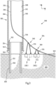
- the Figure 3 shows a schematic view of another embodiment of an offshore wind energy system 300 for an offshore structure. To avoid repetition, only the differences from the previous embodiments are described below and otherwise reference is made to the explanations for the Figures 1 to 2b Firstly, an annular space 352 is formed between the outer surface 358 of the second hollow structure element 340 and the inner surface 310 of the first hollow structure element 306. The annular space 352 is filled with grout 354 (mortar) as an example. As can be seen, at least one radially outward-pointing stop 356 is formed on the outer surface 358 of the second wall 351 in a binding section 344 of the second hollow structure element 340.
- grout 354 memory
- at least one radially outward-pointing stop 356 is formed on the outer surface 358 of the second wall 351 in a binding section 344 of the second hollow structure element 340.
- the cable guide arrangement 304 comprises a plurality of support elements 338.1, 338.2 (in the present case, only two support elements 338.1, 338.2 are shown as an example for the sake of a better overview).
- the support elements 338.1, 338.2 have a different height or distance from the underwater floor surface 322.
- the height of the support elements 338.1, 338.2 is stepped in the radial direction from the first support element 338.1 to the last support element 338.2.
- different cable lengths are provided.
- the at least one support element 338.1, 338.2 is in the present case a cable tensioning arrangement 338.1, 338 that can be anchored to the underwater lake bed 320.
- a cable tensioning arrangement 338.1, 338.2 comprises a cable 370 (or a chain), the ends of which are each connected to an anchor 372 that is at least partially buried in the underwater lake bed 320.
- a cable 370 of a cable tensioning arrangement 338.1, 338.2 is tensioned over the submarine cable 318 in such a way that the submarine cable 318 is supported at least in a vertical direction.
- a force (indicated by the arrow) acts on the submarine cable 318 through the tensioned cable 370.
- the submarine cable 318 can thereby be safely guided from the cable feedthrough 326 to the underwater bottom surface 322.
- At least one cable fixing module can optionally be provided, such as a clip or clamp mechanism.
- a submarine cable 318 can have (evenly) spaced, fixedly mounted cable fixing modules (not shown) to which a rope can be fixed.
- cuffs can be provided on the submarine cable.
- the Figure 4 shows a schematic view of another embodiment of an offshore wind energy system 400 for an offshore structure. To avoid repetition, only the differences from the previous embodiments are described below and otherwise reference is made to the explanations for the Figures 1 to 3 referred to.
- a plurality of support elements 438.1, 438.2 are arranged with a channel-like recess 460 as a cable receptacle 460.
- a support element 438.1, 438.2 can be firmly anchored in the underwater floor 420.
- the support elements 438.1, 438.2 have a different height or distance from the underwater floor surface 422.
- the height of the support elements 438.1, 438.2 is reduced in a step-like manner in the radial direction from the first support element 438.1 to the last support element 438.2.
- the Figure 5 shows a schematic view of another embodiment of an offshore wind energy system 400 for an offshore structure.
- the at least one support element 538 is formed by bulk material 580.
- the bulk material 580 e.g. in the form of rocks 580
- the submarine cable 518 can then be laid on the bulk material 580 and guided through the formed upper surface (in particular a sufficiently wide and sloping plateau) of the bulk material support element 538.
- the bulk material 580 can in particular have a sufficiently large (average) grain size, which in particular prevents scouring of the submarine cable and/or erosion of the bulk material support element 538 as a result of the prevailing ocean current.
- the average grain size can be between 1 mm and 5000 mm.
- the average grain size can be between at least 200 mm and 5000 mm, more preferably between at least 1000 mm and 5000 mm.
- a filling material 582 e.g. grout, gray cast iron, cable cement, etc.
- a filling material 582 can be poured onto the upper surface of the bulk material support element 538, in particular at least partially over the submarine cable 518. This allows the submarine cable 518 to be fixed even more securely.
Landscapes
- Engineering & Computer Science (AREA)
- General Engineering & Computer Science (AREA)
- Structural Engineering (AREA)
- Civil Engineering (AREA)
- Life Sciences & Earth Sciences (AREA)
- Mechanical Engineering (AREA)
- Architecture (AREA)
- General Life Sciences & Earth Sciences (AREA)
- Paleontology (AREA)
- Mining & Mineral Resources (AREA)
- Sustainable Development (AREA)
- Sustainable Energy (AREA)
- Chemical & Material Sciences (AREA)
- Combustion & Propulsion (AREA)
- Power Engineering (AREA)
- Wind Motors (AREA)
- Foundations (AREA)
- Electric Cable Installation (AREA)
- Laying Of Electric Cables Or Lines Outside (AREA)
Description
- Die Erfindung betrifft ein Offshore-Windenergiesystem.
- Vermehrt werden Offshore-Bauwerke errichtet, insbesondere auf dem Meer. So werden zur elektrischen Energieerzeugung bzw. zur Bereitstellung elektrischer Energie aus sogenannten erneuerbaren Energiequellen beispielsweise Offshore-Windparks mit einer Vielzahl von Offshore-Windenergiebauwerken installiert. Offshore-Standorte zeichnen sich üblicherweise durch relativ kontinuierliche Windbedingungen und hohe durchschnittliche Windgeschwindigkeiten aus, so dass vermehrt so genannte Offshore-Windparks errichtet werden.
- In der Regel weist ein Offshore-Windpark eine Vielzahl an Offshore-Windenergiebauwerken auf, wie eine Vielzahl von Offshore-Windkraftanlagen, Messmasten und/oder mindestens eine Offshore-Umspannstation. Über die Offshore-Umspannstation kann der Offshore-Windpark elektrisch beispielsweise mit einer Onshore-Umspannstation oder einer weiteren Offshore-Umspannstation bzw. Offshore-Konverterstation verbunden sein. Eine Onshore-Umspannstation wiederum kann mit einem öffentlichen Stromnetz verbunden sein.
- Eine Offshore-Windkraftanlage ist zum Wandeln der kinetischen Windenergie in elektrische Energie eingerichtet. Zum Übertragen der erzeugten elektrischen Energie zwischen zwei Offshore-Windenergiebauwerken oder einem Offshore-Windenergiebauwerk und einem Onshore-Bauwerk werden Energiekabel in Form von Seekabeln verlegt. Insbesondere kann ein Seekabel mit einem Generator einer Offshore-Windkraftanlage elektrisch verbunden sein.
- Bei Offshore-Windparks, aber auch bei anderen Offshore-Bauwerken (z.B. Plattformen zur Exploration von Gas und/oder Öl), ist es üblich, ein Offshore-Bauwerk durch eine Gründung (z.B. Monopile-, Tripod-, Tripile- oder Jacket-Gründungen) auf bzw. in dem Unterwasserboden, insbesondere einem Meeresboden, direkt zu verankern (auch gründen genannt).
- Eine Gründung verfügt über mindestens ein turmförmiges, insbesondere zylinderförmiges, Hohlstrukturelement (auch turmförmige Gründungsstruktur genannt). Ein Hohlstrukturelement weist in der Regel eine sich in Längsrichtung erstreckende, umlaufende Wandung auf, wobei die (Gründungs-) Wandung unterseitig mit einer unterseitigen Stirnfläche und oberseitig mit einer oberen Stirnfläche begrenzt sein kann.
- Wie bereits beschrieben wurde, ist es beispielsweise bei einer Offshore-Windkraftanlage erforderlich, den generierten elektrischen Strom (bzw. elektrische Energie) durch ein Seekabel zu einem weiteren (Offshore-) Bauwerk z.B. des Windparks zu transportieren.
- Aus dem Stand der Technik ist es bei Offshore-Bauwerken bekannt, ein an eine Offshore-Einrichtung des Offshore-Bauwerks angeschlossenes Seekabel durch so genannte J-tubes zur Unterwasserbodenoberfläche (insbesondere eine Meeresbodenoberfläche) zu führen. Problematisch an J-tubes ist jedoch, dass diese zusätzliche Wellenlasten verursachen können. Zudem können diese durch einen Schiffsanprall beschädigt werden und müssen zudem regelmäßig von Bewuchs befreit werden.
- Zur Lösung dieser Problematik ist es aus dem Stand der Technik bekannt, ein Seekabel zunächst durch den Innen- bzw. Hohlraum des mindestens einen Hohlstrukturelements (insbesondere frei hängend) von der Offshore-Einrichtung nach unten zu führen. In der Nähe der Unterwasserbodenoberfläche (Abstand < 1 m) ist in der Wandung des Hohlstrukturelements eine Kabeldurchführung bzw. Kabelaussparung vorgesehen, durch die das Seekabel von dem Innenraum nach außen zur Unterwasserbodenoberfläche geführt ist.
- Insbesondere bei Gründungen, umfassend ein erstes Hohlstrukturelement und ein zweites Hohlstrukturelement, die ineinander gesteckt sind, aber auch bei anderen Gründungen, stellt die Herausführung des Seekabels eine große Herausforderung dar. Wenn beispielsweise zwei Hohlstrukturelemente in Unterwasserbodenoberflächennähe zusammengesteckt sind und ein Ringraum zwischen der inneren Mantelfläche des zweiten Hohlstrukturelements und der äußeren Mantelfläche des ersten Hohlstrukturelements vergroutet ist und/oder ein so genannter Slip-joint zwischen den Hohlstrukturelementen hergestellt ist, ist die Herausführung eines Seekabels aus dem Innenraum komplex und aufwendig.
- So ist ein gleichzeitiges Durchdringen von zwei konzentrisch Übereinanderliegenden Hohlstrukturelementen erforderlich. Besonders problematisch hieran ist, dass diese Hohlstrukturelemente erst am Installationsort des Offshore-Bauwerks montiert werden und es bei der Montage regelmäßig dazu kommt, dass die Hohlstrukturelemente gegeneinander leicht verdreht installiert werden. Dies hat zur Folge, dass sich die Kabeldurchführungen in den jeweiligen Hohlstrukturelementen nicht überlappen können und daher eine Herausführung eines Seekabels nicht möglich ist. Um dies zu verhindern, ist insbesondere eine äußerst exakte Montage der Hohlstrukturelemente erforderlich. Dies erhöht jedoch den Aufwand der Installation.
- Zudem wird der Ringraum zwischen den Hohlstrukturelementen regelmäßig vergroutet. Um zu verhindern, dass das Groutmaterial durch die im Bereich des Ringraums angeordneten Kabeldurchführungen in den Innenraum dringt, ist eine besondere Abdichtung der Kabeldurchführungen gegen das Groutmaterial erforderlich. Diese Abdichtung darf bei der Montage der Hohlstrukturelemente nicht beschädigt werden. Dies erhöht den Aufwand der Installation zusätzlich. Grundsätzlich wäre eine Lösung der vorbeschriebenen Problematik, das Seekabel oberhalb des Überlappbereichs bzw. des Ringraumbereichs aus dem Innenraum herauszuführen. Dies wird im Stand der Technik bisher jedoch als nicht realisierbar erachtet. Insbesondere bei den dann großen Abständen zur Unterwasserbodenoberfläche von mehr als 5 m ist das Seekabel den starken Strömungskräften auf dieser Strecke ungeschützt ausgesetzt. Dies hätte eine übermäßige Belastung des Seekabels zur Folge, die mit den am Markt verfügbaren Kabelschutzsystemen nicht abzufangen ist.
- Gattungsgemäße Offshore- Windenergie systeme mit mindestens einer Kabelführungsanordnung an einem Hohlstrukturelement sind von
EP3696326A1 ,WO2020/074421A1 ,WO2020/157196A1 und vonCN104934920A bekannt. Daher liegt der Erfindung die Aufgabe zugrunde, ein Offshore-Windenergiesystem bereitzustellen, bei dem die zuvor beschriebenen Nachteile zumindest reduziert sind und insbesondere eine Führung des Seekabels aus einer Gründung heraus zu einer Unterwasserbodenoberfläche in einfacherer und aufwandsreduzierter Weise möglich ist. - Die Aufgabe ist gelöst durch ein Offshore-Windenergiesystem nach Anspruch 1.
- Indem im Gegensatz zum Stand der Technik gemäß Anspruch 1 ein Offshore-Windenergiesystem mit einer Kabelführungsanordnung bereitgestellt wird, die ein durch eine Kabeldurchführung austretendes Seekabel zur
- Unterwasserbodenoberfläche führt, werden die Nachteile des Stands der Technik zumindest reduziert. Insbesondere ist eine Führung des Seekabels aus einer Gründung heraus zu einer Unterwasserbodenoberfläche in einfacherer und aufwandsreduzierter Weise möglich.
- Durch die Kabelführungsanordnung wird insbesondere die Belastung des Seekabels aufgrund von Strömungskräften, die auf das Seekabel wirken können, reduziert. Dies ermöglicht es, das Seekabel auch in einer Höhe von über 5 m über der Unterwasserseebodenoberfläche (in einem initialen Installationszustand der Gründung) aus der Gründung hinauszuführen.
- Ein erfindungsgemäßes Offshore-Windenergiesystem umfasst mindestens eine Gründung und mindestens eine Kabelführungsanordnung.
- Eine Gründung ist insbesondere Teil eines Offshore-Bauwerks und dient vorzugsweise dem Tragen mindestens einer Offshore-Einrichtung des Offshore-Bauwerks. Ein Offshore-Bauwerk ist vorzugsweise ein Offshore-Windenergiebauwerk, wie eine Offshore-Windkraftanlage, ein Offshore-Messmast oder eine Offshore-Umspannstation. Insbesondere ist es ein Offshore-Bauwerk, an dem mindestens ein Seekabel angeschlossen ist. Insbesondere kann das Seekabel an die Offshore-Einrichtung des Offshore-Bauwerks angeschlossen sein. So kann ein Offshore-Bauwerk auch eine Bohr- oder Förderplattform oder eine andere Offshore-Plattform sein, vorzugsweise eingerichtet zur Gewinnung, Umwandlung und/oder Speicherung von Energie, wie z.B. eine Offshore-Anlage zur Produktion von Wasserstoff (sofern ein Seekabel an das Offshore-Bauwerk angeschlossen ist).
- Wie bereits beschrieben wurde, kann ein Offshore-Bauwerk eine Offshore-Einrichtung umfassen, die durch die Gründung in einem Unterwasserboden, insbesondere ein Meeresboden, befestigt sein kann. Ein Offshore-Bauwerk kann insbesondere durch die Offshore-Einrichtung (z.B. eine Plattform, eine Gondel, Turm, Generator, Rotor, Umspannvorrichtung und/oder dergleichen) und die mindesten eine Gründung gebildet sein.
- Die Gründung umfasst ein erstes Hohlstrukturelement bzw. eine erste turmförmige Gründungsstruktur. Ein Hohlstrukturelement ist vorzugsweise zylinderförmig. Ein zylinderförmiges Hohlstrukturelement kann insbesondere ein Hohlpfahl sein.
- Das erste Hohlstrukturelement weist eine sich in Längsrichtung (also entlang der Längsachse des Hohlstrukturelements) erstreckende, umlaufende erste Wandung auf.
- Insbesondere kann ein Hohlstrukturelement eine kreisförmige Querschnittsfläche aufweisen. Bei anderen Varianten kann auch eine andere Querschnittsfläche vorgesehen sein, wie eine ovalförmige.
- Eine Wandung eines Hohlstrukturelements kann zwei distale Enden aufweisen, die jeweils durch gegenüberliegende Stirnflächen begrenzt sind. Eine erste Stirnfläche kann eine oberseitige Stirnfläche sein und eine zweite Stirnfläche kann eine unterseitige Stirnfläche sein. Ober- und Unterseite können durch die Position des Hohlstrukturelements im finalen Installationszustand definiert sein. Dabei ist im Installationszustand die untere Stirnfläche in Richtung des Unterwasserbodens angeordnet. Die obere Stirnfläche kann insbesondere zumindest aus dem Unterwasserboden in Richtung der Wasseroberfläche ragen.
- In der ersten Wandung ist eine die erste Wandung durchbrechende Kabeldurchführung bzw. Aussparung zur Durchführung eines Seekabels angeordnet. Eine Kabeldurchführung ist insbesondere derart gebildet, dass ein Seekabel aus dem Inneren des ersten Hohlstrukturelements nach außen geführt werden kann. Insbesondere kann das Seekabel in einem durch die erste Wandung gebildeten Hohlraum bzw. Innenraum (frei) hängend angeordnet sein und durch die Kabeldurchführung aus dem Hohlraum nach außen geführt sein.
- Bei beispielsweise einer Offshore-Windkraftanlage kann in einem montierten Zustand nicht nur die Gründung, sondern auch die Offshore-Einrichtung montiert sein, umfassend einen Turm mit Gondel samt Turbine und Windrad. Von dem Generator, der in der Gondel sitzt, kann das Seekabel durch den Turm und das erste Hohlstrukturelement hin zu der Kabeldurchführung verlaufen und dort aus der Gründung herausgeführt sein.
- Die auf ein nach außen geführtes Seekabel wirkenden Kräfte können reduziert werden, wenn an der äußeren Mantelfläche bzw. Außenseite der ersten Wandung des ersten Hohlstrukturelements eine Kabelführungsanordnung angeordnet ist. Eine Anordnung an der äußeren Mantelfläche meint insbesondere, dass die Kabelführungsanordnung außerhalb der Gründung angeordnet ist. Erfindungsgemäß umfasst eine Anordnung an der äußeren Mantelfläche eine radiale Beabstandung der Kabelführungsanordnung von der äußeren Mantelfläche der Gründung.
- Die Kabelführungsanordnung erstreckt sich, ausgehend von dem ersten Hohlstrukturelement, in eine radiale Richtung. Vorzugsweise kann die Kabelführungsanordnung zu der Kabeldurchführung ausgerichtet sein. Die Kabelführungsanördnung ist eine separate Anordnung und kann insbesondere auf der Unterwasserbodenoberfläche angeordnet sein, beispielsweise an dem Unterwasserboden befestigt sein.
- Gemäß der Erfindung berührt die Kabelführungsanordnung und dessen mindestens ein Element nicht direkt die äußere Mantelfläche des ersten Hohlstrukturelements und ist in einem radialen Abstand zwischen 0,25 m und 3m von der äußeren Mantelfläche angeordnet, vorzugsweise in einem radialen Abstand von bis zu 5m.
- Die Kabelführungsanordnung ist derart eingerichtet, dass das austretende Seekabel in radialer Richtung von der Kabeldurchführung zu einer Unterwasserbodenoberfläche des Unterwasserbodens geführt wird. Ein Führen des Seekabels meint vorliegend insbesondere, dass die Bewegungsfreiheit des Seekabels in horizontaler und/oder vertikaler Richtung durch die Kabelführungsanordnung zumindest eingeschränkt ist. Hierdurch können die durch eine Strömung auf das Seekabel ausgeübten Kräfte und damit die Belastung des Seekabels reduziert werden.
- Es versteht sich, dass zwei oder mehr Kabeldurchführungen vorgesehen sein können, beispielsweise für eine entsprechende Anzahl an Seekabeln. Ferner versteht es sich, dass eine entsprechende Anzahl an Kabelführungsanordnungen vorgesehen sein kann.
- Gemäß einer bevorzugten Ausführungsform des Offshore-Windenergiesystems kann die Kabeldurchführung des ersten Hohlstrukturelements in einem Installationszustand der Gründung zumindest über 5 m oberhalb der Unterwasserbodenoberfläche liegen, insbesondere über 6 m, insbesondere bevorzugt zwischen 8 m und 12 m. Anders ausgedrückt, kann der Abstand zwischen der Unterwasserbodenoberfläche und insbesondere der Unterkante der Kabeldurchführung größer sein als 5 m, vorzugsweise größer als 6 m und insbesondere bevorzugt zwischen 8 m und 12 m liegen.
- Die Unterwasserbodenoberfläche ist vorliegend insbesondere als die vertikale Ebene definiert, welche in den Planunterlagen des Offshore-Bauwerks (insbesondere eines Offshore-Windparks) als Wassertiefe unterhalb der Bezugsebene LAT (lowest Astronomical tide - niedrigster Wasserstand) angegeben ist. Hierbei versteht es sich, dass sich die Wassertiefe und damit der Abstand zur Kabeldurchführung nach einer Installation des Offshore-Bauwerks ändern können, beispielsweise durch eine Abtragung oder Anhäufung von Sedimenten und/oder einem Anschütten eines Kolkschutzes Insbesondere kann das Seekabel aufgrund der Anordnung der Kabelführungsanordnung in sicherer Weise aus dem ersten Hohlstrukturelement auch bei den genannten Höhen herausgeführt werden. Dies ermöglicht es, in dem Bereich zwischen 0 m und 5 m, vorzugsweise 8 m, Dichtungsmaßnahmen und/oder ein Vergrouten vorzunehmen, ohne dass hierdurch ein Herausführen des Seekabels komplex und aufwendig wird.
- Gemäß einer bevorzugten Ausführungsform des Offshore-Windenergiesystems kann die Gründung ein zweites Hohlstrukturelement umfassen. Das zweite Hohlstrukturelement kann einen Überlappabschnitt aufweisen, der (außenseitig oder innenseitig) über einen Endabschnitt (auch Überlappabschnitt genannt) des ersten Hohlstrukturelement ragt, und einen Einbindeabschnitt, der zumindest teilweise in einem Unterwasserboden einbindbar ist. Die Kabeldurchführung des ersten Hohlstrukturelements kann (in einem Installationszustand der Gründung) zumindest oberhalb des Überlappabschnitts (also oberhalb des oberen Endes des zweiten Hohlstrukturelements) angeordnet sein. Insbesondere können das erste Hohlstrukturelement und das zweite Hohlstrukturelement in dem Überlappabschnitt ineinandergesteckt sein. Vorzugsweise können zwei konzentrische und ineinandergesteckte Rohre als Gründung ausgebildet sein. Beispielsweise kann das erste Hohlstrukturelement einen Außendurchmesser aufweisen, der zu einem Innendurchmesser des zweiten Hohlstrukturelements kongruent ist. Alternativ kann das erste Hohlstrukturelement einen Innendurchmesser aufweisen, der zu einem Außendurchmesser des zweiten Hohlstrukturelements kongruent ist.
- Das erste Hohlstrukturelement kann auch als so genanntes Transition Piece bzw. Übergangsstück bezeichnet werden und das zweite Hohlstrukturelement als Einbindeelement. Insbesondere ist in einem Gründungszustand der Gründung das Einbindeelement mit einer bestimmten Einbindetiefe bzw. Einbindelänge (z.B. zwischen 7 und 20 m) in den Unterwasserboden eingebunden bzw. gegründet.
- Das zweite Hohlstrukturelement umfasst insbesondere eine sich in Längsrichtung erstreckende, umlaufende zweite Wandung. Vorzugsweise ist in der zweiten Wandung keine Kabeldurchführung angeordnet.
- Das erste Hohlstrukturelement weist insbesondere einen Übergangsabschnitt auf, der stirnseitig aus dem zweiten Hohlstrukturelement herausragt. Insbesondere kann ein (erstes und/oder zweites) Hohlstrukturelement bevorzugt monolithisch und rohrförmig gebildet sein und sich in einer Längsrichtung erstrecken. Diese Längsrichtung des ersten Hohlstrukturelements ist im Installationszustand bevorzugt kollinear mit der Längsrichtung des zweiten Hohlstrukturelements.
- Das Transition Piece kann mindestens eine Schiffsanlandungseinrichtung mit Leiter aufweisen.
- Der Vorteil einer Gründung, die aus zwei Hohlstrukturelementen gebildet und am Installationsort montierbar ist, ist insbesondere, dass das Gewicht eines zu transportierenden Hohlstrukturelements, insbesondere eines Pfahls, deutlich reduziert werden kann.
- Das erste Hohlstrukturelement kann mittels einer Grout-Verbindung oder im Slip-Joint-Verfahren mit dem zweiten Hohlstrukturelement verbunden sein/werden.
- Zwischen dem ersten und dem zweiten Hohlstrukturelement kann in einem ein- bzw. übergesteckten Zustand im Bereich des Überlappabschnitts des zweiten Hohlstrukturelements ein (umlaufender) Ringraum vorgesehen sein. Gemäß einer Ausführungsform des Offshore-Windenergiesystems kann in einem Ringraum zwischen der inneren Mantelfläche des zweiten Hohlstrukturelements und der äußeren Mantelfläche des ersten Hohlstrukturelements eine an den Mantelflächen anliegende Dichtung umlaufend angeordnet sein. Alternativ kann in einem Ringraum zwischen der äußeren Mantelfläche des zweiten Hohlstrukturelements und der inneren Mantelfläche des ersten Hohlstrukturelements eine an den Mantelflächen anliegende Dichtung umlaufend angeordnet sein. Insbesondere in Längsrichtung des ersten Hohlstrukturelements kann die Dichtung unterhalb der Kabeldurchführung angeordnet sein.
- Alternativ oder zusätzlich kann, gemäß einer bevorzugten Ausführungsform des Offshore-Windenergiesystems ein Ringraum zwischen der inneren Mantelfläche des zweiten Hohlstrukturelements und der äußeren Mantelfläche des ersten Hohlstrukturelements zumindest teilweise vergroutet sein. Alternativ kann ein Ringraum zwischen der äußeren Mantelfläche des zweiten Hohlstrukturelements und der inneren Mantelfläche des ersten Hohlstrukturelements zumindest teilweise vergroutet sein. Eine Oberkante der Groutverbindung kann in Längsrichtung der Gründung zumindest unterhalb einer Unterkante der Kabeldurchführung angeordnet sein. Die Grout-Verbindung kann so hergestellt werden, dass diese vollständig unterhalb der Kabeldurchführungen im Überlappbereich ist. In diesem Fall kann die Dichtung vorzugsweise entfallen.
- Wenn eine Dichtung vorgesehen ist, kann die Dichtung vorzugsweise expandierbar sein, derart, dass das Volumen der Dichtung nach der Montage der Hohlstrukturelemente vergrößerbar ist, insbesondere dass die Dichtung pneumatisch oder hydraulisch mit einem Füllmaterial beaufschlagt ist. Der Ringraum kann relativ schmal sein, insbesondere wenn keine Grout-Verbindung, sondern eine Slip-Joint-Verbindung, hergestellt wird. Beim Einführen des ersten Hohlstrukturelements in oder über das zweite Hohlstrukturelement kann nur eine geringe Toleranz erlaubt sein. Um zu verhindern, dass die Dichtung das Einführen des Übergangsstücks in das Hohlstrukturelement behindert oder beim Einführen beschädigt wird, kann die Dichtung expandierbar ist. Insbesondere ist die Dichtung so geformt, dass deren Volumen nach der Montage der Hohlstrukturelemente vergrößerbar ist. Die Dichtung kann beispielsweise aufgepumpt werden, sei es pneumatisch oder hydraulisch, indem sie mit einem Füllmaterial beaufschlagt wird. Im Inneren der Dichtung kann ein Volumen als Hohlraum vorgehalten werden. Dieses Volumen kann nach der Montage mit dem Füllmaterial unter Druck gefüllt werden, so dass die Dichtung den Ringspalt zwischen Hohlstrukturelement und Übergangsstück im Bereich der Kabeldurchführungen verschließt. Alternativ kann die Dichtung quellfähiges (z.B. tonhaltiges) Material aufweisen, welches bei Kontakt mit Wasser aufquillt.
- Ferner können an einer oberen stirnseitigen Kante des zweiten Hohlstrukturelements angeordnete Einführhilfen mit an einer unteren stirnseitigen Kante des ersten Hohlstrukturelements angeordneten Einführhilfen zusammenwirken, derart, dass eine relative Ausrichtung der Azimutwinkel der Hohlstrukturelemente zueinander definiert ist. Die Einführhilfen können ineinandergreifende, radial nach innen und radial nach außen ragende Vorsprünge und Ausnehmungen sein. Hierdurch kann die Montage des ersten und zweiten Hohlstrukturelements vereinfacht werden.
- Gemäß einer weiteren Ausführungsform, kann an der inneren Mantelfläche der Wandung in einem Einbindeabschnitt des zweiten Hohlstrukturelements mindestens ein radial nach innen weisender Anschlag gebildet sein. Insbesondere alternativ hierzu kann an der äußeren Mantelfläche der Wandung in einem Einbindeabschnitt des zweiten Hohlstrukturelements mindestens ein radial nach außen weisender Anschlag gebildet sein. In einem eingesteckten Zustand kann die untere Stirnseite des ersten Hohlstrukturelements auf dem mindestens einen Anschlag aufliegen.
- Eine Wandung eines Hohlstrukturelements kann aus Metall gebildet sein, insbesondere Stahl. Gemäß einer bevorzugten Ausführungsform kann eine (erste und/oder zweite) Wandung eines (ersten und/oder zweiten) Hohlstrukturelements aus einem mineralischen Baustoff gebildet sein.
- Gemäß einer Ausführungsform des anmeldungsgemäßen Offshore-Windenergiesystems kann der mineralische Baustoff zumindest in Teilen Zement enthalten. Der mineralische Baustoff ist vorzugsweise Beton, der aus Zement, Kies, Sand und Wasser angemischt ist und insbesondere nach dem Vergießen ausgehärtet ist.
- Für eine gute Tragfähigkeit hat sich herausgestellt, dass der Wasser-Zement-Wert (w/z) des mineralischen Baustoffs kleiner als 0,45, insbesondere kleiner als 0,35 und insbesondere bevorzugt kleiner als 0,3 sein kann.
- Die insbesondere bei Windkraftanlagen auftretenden Momente und Scherkräfte können durch das Hohlstrukturelement insbesondere dann ausreichend aufgenommen werden, wenn der Baustoff eine Festigkeitsklasse von zumindest C40/50, bevorzugt C70/85, insbesondere C100/115 nach EN 206 und EN1992 aufweist.
- Eine über die Lebensdauer eines Offshore-Bauwerks, insbesondere einer Offshore-Windkraftanlage, ausreichende Langzeitstabilität der Gründung, insbesondere bei dauerhafter Penetration durch Wasser, kann insbesondere dadurch erreicht werden, dass der mineralische Baustoff einen Porengehalt (Luftporen) von weniger als 5 %, bevorzugt weniger als 3 %, insbesondere weniger als 2 % aufweist. Die Gesamtporosität gemessen mit Quecksilberdruckporosität sollte nach 28 Tagen P28d < 12 Vol-% und nach 90 Tagen P90d < 10 Vol-% sein.
- Insbesondere bei einer dauerhaften Penetration von Wasser bei einer Installation der Gründung kann eine ausreichende Lebensdauer dadurch erreicht werden, dass der mineralische Baustoff bei einer Quecksilberdruckporosimetrischen Messung eine Porosität von P28d < 12 Vol-% aufweist, wie bereits beschrieben wurde. P28d ist eine Messung über 28 Tage. Die Porosität ist dabei bevorzugt auch kleiner als 10 Vol.-%. Bei P90d, das heißt einer Messung über 90 Tage, ist die Porosität bevorzugt < 10 Vol.- %, insbesondere < 8 Vol.-%.
- Eine ausreichende Tragfähigkeit der Gründung kann insbesondere dadurch erreicht werden, dass der mineralische Baustoff einen Zementgehalt von zumindest 350 kg/m3, bevorzugt zumindest 450 kg/m3, insbesondere bevorzugt zumindest 650 kg/m3 aufweist.
- Ferner kann eine Wandung mechanisch vorgespannt sein. Durch die Vorspannung können Risse überdrückt und somit die Oberflächen weitestgehend frei von Zugspannung gehalten werden, was bei insbesondere schwankenden Drehmomentbelastungen vorteilhaft ist. Die Vorspannkraft ist dabei bevorzugt 5%, insbesondere mehr als 15% größer als die Druckfestigkeit der Gründungswandung. Die Vorspannkraft wird vorzugsweise in Längsrichtung aufgebracht.
- Für eine noch höhere Stabilität, insbesondere bei dynamischen Umgebungsbedingungen, kann, gemäß einer weiteren Ausführungsform, der mineralische Baustoff (metallisch) armiert sein. Die metallische Armierung ist insbesondere eine Stahlarmierung. Die Armierung kann durch Fasern oder Armiereisen gegeben sein. Eine Faserarmierung kann auch durch Kohlefaser, Glasfaser oder Metallfaser erreicht werden.
- Die Armierung kann so gebildet sein, dass diese bei 90% der Messstellen, bevorzugt bei 98% der Messstellen, zumindest als 26 mm, bevorzugt zumindest als 40 mm Betondeckung aufweist.
- Der mineralische Baustoff kann mit ferritisch nichtrostendem Betonstahl armiert sein. Die Armierung kann einen Chromgehalt von 18 M% nicht überschreiten. Die Armierung kann Molybdänbestanteile aufweisen.
- Der mineralische Baustoff kann mit austenitisch nichtrostendem Betonstahl armiert sein. Die Armierung kann zumindest 5 M% aufweisen, insbesondere zwischen 5 M% bis 14 M% Nickel und/oder zwischen 12 M% bis 22 M%, insbesondere 15 M% bis 20 M% Chrom.
- Der mineralische Baustoff kann mit ferritisch-austenitisch nichtrostendem Betonstahl armiert sein. Die Armierung kann zumindest 18 M%, insbesondere zwischen 15 M% - 20 M% Chrom und 2 M% - 8 M% Nickel und optional Molybdän aufweisen.
- Für eine erhöhte Standfestigkeit wird vorgeschlagen, dass der mineralische Baustoff versiegelt sein kann, insbesondere mit einer Dichtungsfolie. Eine solche Dichtungsfolie kann beispielsweise eine Aluminium-Butyl-Dichtfolie sein.
- Gemäß einer weiteren Ausführungsform des Offshore-Windenergiesystems kann die Kabelführungsanordnung mindestens ein (Kabel-) Stützelement umfassen, eingerichtet zumindest zur vertikalen Stützung des Seekabels. Indem mindestens ein Stützelement mit einer vertikalen Stützfunktion bereitgestellt wird, das das Seekabel zumindest in eine vertikale Richtung stützt, kann bereits eine signifikante Belastungsreduktion für das Seekabel erzielt werden. Eine vertikale Stützung meint insbesondere, dass die Bewegungsfreiheit des Seekabels nach unten und/oder oben eingeschränkt ist.
- Darüber hinaus kann, gemäß einer bevorzugten Ausführungsform des Offshore-Windenergiesystems, sich eine Höhe (in Bezug zur Unterwasserbodenoberfläche) des mindestens einen Stützelements in radialer Richtung (ausgehend von der äußeren Mantelfläche) stufenförmig oder stetig reduzieren. Vorzugsweise kann mindestens ein keil- bzw. rampenförmiges Stützelement vorgesehen sein, welches sich in einer radialen Richtung erstreckt. Die Höhe des keil- bzw. rampenförmigen Stützelements kann sich vorzugsweise stetig reduzieren. Beispielsweise kann eine untere Oberfläche (insbesondere ein Fußabschnitt) des keil- bzw. rampenförmigen Stützelements im Wesentlichen waagerecht bzw. horizontal sein und die obere Oberfläche (insbesondere ein Kopfabschnitt) eine schräg verlaufende Fläche sein. Die untere Oberfläche kann in einem Installationszustand die Unterwasserbodenoberfläche kontaktieren oder sogar in dem Unterwasserboden eingebunden sein. Die obere Oberfläche kann das Seekabel tragen und zumindest in eine vertikale Richtung stützen.
- Ferner kann eine Mehrzahl von einzelnen Stützelementen (beispielsweise in Form von einer Mehrzahl an Falllanzen) vorgesehen sein, wobei sich die Mehrzahl der Stützelemente einer Kabelführungsanordnung in eine radiale Richtung erstrecken. Bei einer Mehrzahl von einzelnen Stützelementen kann sich die Höhe der in radialer Richtung angeordneten Stützelemente nach und nach bzw. stufenförmig, also von Stützelement zu Stützelement, reduzieren.
- Die Höhe meint vorliegend insbesondere den Abstand zwischen dem das Seekabel kontaktierenden Teils (beispielsweise die obere Oberfläche) des mindestens einen Stützelements und der Unterwasserbodenoberfläche (bei Annahme einer nahezu planen Unterwasserbodenoberfläche über die gesamte radiale Erstreckungsrichtung der Kabelführungsanordnung).
- Grundsätzlich kann das mindestens eine Stützelement aus einem beliebigen Material gebildet und eine beliebige Form haben, so lange sichergestellt ist, dass das mindestens eine Stützelement das Seekabel von der Kabeldurchführung zur Unterwasserbodenoberfläche zumindest vertikal gestützt führt. Beispielsweise kann das mindestens eine Stützelement durch Schüttgut gebildet sein. Das Schüttgut kann an einer Außenwand rampenförmig aufgeschüttet sein. Das Seekabel kann dann auf das Schüttgut abgelegt und durch die gebildete obere Oberfläche des Schüttgutstützelements geführt sein. Das Schüttgut kann insbesondere eine hinreichend große (durchschnittliche) Korngröße aufweisen, die insbesondere ein Auskolken des Seekabels und/oder ein Abtragen des Schüttgutstützelements infolge der vorherrschenden Meeresströmung verhindert.
- Die durchschnittliche Korngröße kann zwischen 1 mm und 5000 mm liegen. Bevorzugt kann durchschnittliche Korngröße zwischen mindestens 200 mm und 5000 mm liegen, weiter bevorzugt zwischen mindestens 1000 mm und 5000 mm.
- Gemäß einer bevorzugten Ausführungsform des Offshore-Windenergiesystems kann das mindestens eine Stützelement ein Betonfertigbauteil sein. Insbesondere kann das Betonfertigbauteil vorgefertigt sein, insbesondere aus einem zuvor beschriebenen mineralischen Baustoff. Das mindestens eine Betonfertigbauteil kann dann neben der Gründung (ausgerichtet zur Kabeldurchführung) angeordnet werden, insbesondere abgesenkt werden. Eine einfache Installation des Offshore-Windenergiesystems ist möglich.
- Vorzugsweise kann ein vorbeschriebenes keil- bzw. rampenförmiges Stützelement ein einzelnes (einstückiges) Betonfertigbauteil sein. Auch kann ein derartiges Stützelement aus einer Mehrzahl von Betonfertigbauteilen gebildet sein.
- Bei anderen Varianten kann das mindestens eine Stützelement auch ein Metallfertigbauteil sein, wie ein Stahlfertigbauteil.
- Gemäß einer weiteren Ausführungsform des Offshore-Windenergiesystems kann das mindestens eine Stützelement eine an dem Unterwasserseeboden verankerbare Seilspannungsanordnung sein. Insbesondere kann eine Mehrzahl von verankerbaren Seilspannungsanordnungen als Kabelführungsanordnung in einer radialen Richtung hintereinander angeordnet sein. Ein Seil oder eine Kette einer Seilspannungsanordnung kann über das zu führende Seekabel positioniert sein. Die Enden des Seils bzw. der Kette können in dem Unterwasserseeboden (beispielsweise durch geeignete Anker) verankert sein, insbesondere derart, dass das Seil bzw. die Kette über dem Seekabel verspannt ist. Durch die Verspannung kann eine zumindest in vertikale Richtung (insbesondere in Richtung Unterwasserbodenoberfläche) wirkende Kraft auf das Seekabel ausgeübt werden. Hierdurch kann das Seekabel zumindest in vertikale Richtung gestützt werden. An dem Seekabel können Kabelfixiermodule (beispielsweise Manschetten) angeordnet sein, um das Seil bzw. die Kette an dem Seekabel zu fixieren.
- Wie bereits beschrieben wurde, kann eine Mehrzahl von Seilspannungsanordnungen angeordnet sein, wobei die Länge des Seils bzw. der Kette, ausgehend von der äußeren Mantelfläche der ersten Wandung, in radialer Richtung (in einem verankerten und insbesondere verspannten Zustand) sich reduzieren kann. Die Länge ist insbesondere die Länge zwischen den beiden Ankern (unter der Annahme, dass sämtliche Anker gleich tief eingegraben sind).
- Gemäß einer bevorzugten Ausführungsform des Offshore-Windenergiesystems kann das mindestens eine Stützelement eine Kabelaufnahme zum Führen des Seekabels aufweisen. Die Form der Kabelaufnahme kann insbesondere zu der (Außen-) Form des Seekabels korrespondieren. Indem eine derartige Kabelaufnahme vorgesehen ist, kann das Seekabel sicher geführt und insbesondere in vertikaler Richtung, vorzugsweise auch in horizontaler Richtung, gestützt werden.
- Besonders bevorzugt kann die Kabelaufnahme eine kanalartige und in eine radiale Richtung verlaufende Vertiefung in einer oberseitigen Oberfläche des mindestens einen Stützelements sein. Wenn die Kabelführungsanordnung durch eine Mehrzahl von Stützelementen gebildet ist, kann vorzugsweise jedes Stützelement eine derartige Vertiefung aufweisen. Die Stützelemente können so aufgestellt sein, dass die jeweiligen Vertiefungen zueinander ausgerichtet sind.
- Insbesondere kann ein (Innen-) Durchmesser der Vertiefung zumindest größer sein als ein Außendurchmesser des Seekabels.
- Vorzugsweise kann die kanalartige Vertiefung einen ¾ Kreis (Querschnittsansicht) mit Kabelöffnung bilden, entweder als nach oben geöffneter durchgehender Schlitz oder mit einer am von dem Hohlstrukturelement entfernten Ende angeordneten Öffnung mit einer Breite, die größer ist als der Kabeldurchmesser, vorzugsweise Kabeldurchmesser plus 5 mm, insbesondere bevorzugt Kabeldurchmesser plus 20 mm.
- Für eine noch weitere Reduzierung der Belastung des Seekabels - auch bei starken Strömungen - kann, gemäß einer bevorzugten Ausführungsform des Offshore-Windenergiesystems, die Kabelführungsanordnung mindestens ein Kabelfixiermodul umfassen. Das mindestens eine Kabelfixiermodul kann eingerichtet sein zum Fixieren des Seekabels an der Kabelführungsanordnung. Insbesondere kann das mindestens eine Kabelfixiermodul mit dem mindestens einen Stützelement zusammenwirken, derart, dass das Seekabel an dem Stützelement fixiert wird, insbesondere noch weiter in der Bewegungsfreiheit beschränkt wird.
- Vorzugsweise kann das mindestens eine Kabelfixiermodul ein Klippmechanismus (insbesondere mindestens eine Klammer) sein. Ein Klippmechanismus ermöglicht insbesondere ein Festklammern des Seekabels an dem mindestens einen Stützelement. Ein Klippmechanismus ist insbesondere in einfacher Weise zu installieren.
- Alternativ oder zusätzlich kann das mindestens eine Kabelfixiermodul ein Verfüllbaustoff sein, insbesondere ein Kabelzement (z.B. CableCem®). Durch die Verwendung eines mineralischen Verfüllbaustoffs kann das Seekabel sicher fixiert werden. Ein weiterer Vorteil eines Verfüllbaustoffs, insbesondere eines Kabelzements, ist die gute Wärmeleitfähigkeit. Der geringe thermische Widerstand von einem Kabelzement sorgt insbesondere für eine exzellente Wärmeableitung und damit für einen geringeren Energieverlust im Kabelstrang.
- Bevorzugt kann bei einem Schüttgutstützelement für eine sichere Fixierung des Seekabels ein Verfüllbaustoff (z.B. aus Grauguß) verwendet werden.
- Ein weiterer Aspekt der Erfindung ist ein Offshore-Bauwerk, insbesondere ein Offshore-Windenergiebauwerk. Das Offshore-Bauwerk ist gemäß Anspruch 14.
- In der Zeichnung zeigt
- Fig. 1
- eine schematische Ansicht eines Ausführungsbeispiels eines OffshoreBauwerks mit einem Ausführungsbeispiel eines Offshore-Windenergiesystems gemäß der Erfindung,
- Fig. 2
- eine schematische Ansicht eines weiteren Ausführungsbeispiels eines Offshore-Windenergiesystems,
- Fig. 2a
- eine schematische Ansicht eines Ausführungsbeispiels einer in dem Ausführungsbeispiel nach
Figur 2 eingesetzten Kabelführungsanordnung, - Fig. 2b
- eine schematische Ansicht eines weiteren Ausführungsbeispiels einer in dem Ausführungsbeispiel nach
Figur 2 eingesetzten Kabelführungsanordnung, - Fig. 3
- eine schematische Ansicht eines weiteren Ausführungsbeispiels eines Offshore-Windenergiesystems gemäß der vorliegenden Erfindung,
- Fig. 4
- eine schematische Ansicht eines weiteren Ausführungsbeispiels,
- Fig. 5
- eine schematische Ansicht eines weiteren Ausführungsbeispiels eines Offshore-Windenergiesystems.
- Nachfolgend werden für gleiche Elemente gleiche Bezugszeichen verwendet. Ferner bezeichnet z nachfolgend die vertikale Achse bzw. Richtung und r die radiale Richtung. Darüber hinaus beziehen sich die Ausdrücke "unten", "unteren" etc. und "oben", "oberen" etc. insbesondere auf die vertikale Achse z und insbesondere auf den Installationszustand der Gründung bzw. des Offshore-Bauwerks.
- Die
Figur 1 zeigt eine schematische Ansicht eines Ausführungsbeispiels eines Offshore-Bauwerks 114 mit einem Ausführungsbeispiel eines Offshore-Windenergiesystems 100 gemäß der vorliegenden Erfindung. - Als Offshore-Bauwerk 114 ist vorliegend beispielhaft ein Offshore-Windenergiebauwerk 114 in Form einer Offshore-Windkraftanlage 114 dargestellt. Vorliegend sind das Offshore-Bauwerk 114 und damit eine Gründung 102 des Offshore-Bauwerks 114 in einem Installationszustand dargestellt. Die nachfolgenden Ausführungen lassen sich in einfacher Weise auf andere Offshore-Bauwerke übertragen.
- Das Offshore-Bauwerk 114 umfasst mindestens ein Offshore-Windenergiesystem 100 und mindestens eine Offshore-Einrichtung 116 (vorliegend z.B. Turm, Rotor, Generator etc.). Insbesondere ist an die Offshore-Einrichtung 116 ein Seekabel 118 angeschlossen, um insbesondere die generierte elektrische Energie bzw. den generierten elektrischen Strom zu einer weiteren Entität zu transportieren.
- Ein Seekabel 118 ist vorliegend insbesondere ein Energiekabel, insbesondere ein Mittelspannungskabel 118 mit einer Leistungskapazität zwischen 3 MW und 70 MW, vorzugsweise zwischen 9 MW und 60 MW, oder ein Hochspannungskabel 118 mit einer Leistungskapazität zwischen 70 MW und 2,5 GW, vorzugsweise zwischen 360 MW und 1500 MW.
- Das Offshore-Windenergiesystem 100 umfasst eine Gründung 102 und eine Kabelführungsanordnung 104, die benachbart zu der Gründung 102 angeordnet ist.
- Die Gründung 102 umfasst vorliegend ein erstes Hohlstrukturelement 106 bzw. eine erste turmförmige Gründungsstruktur 106. Das erste Hohlstrukturelement 106 umfasst eine sich in Längsrichtung (also entlang der Längsachse des Hohlstrukturelements 106) erstreckende, umlaufende erste Wandung 105.
- Die erste Wandung 105 ist am unteren Ende des ersten Hohlstrukturelements 106 unterseitig mit einer unterseitigen Stirnfläche begrenzt. Am oberen Ende des ersten Hohlstrukturelements 106 ist die erste Wandung durch eine oberseitige Stirnfläche begrenzt.
- Vorzugsweise weist das erste Hohlstrukturelement 106 eine kreisförmige Querschnittsfläche auf. Bei anderen Varianten kann auch eine andere Querschnittsform vorgesehen sein, wie eine elliptische oder ovale. Insbesondere kann das erste Hohlstrukturelement 106 als Hohlpfahl 106 mit einem Innenraum 112 gebildet sein. Durch den Innenraum 112 kann das Seekabel 118 nach unten geführt sein, insbesondere in dem Innenraum 112 frei hängend angeordnet sein.
- Die erste Wandung 105 weist eine innere Mantelfläche 110 bzw. Innenwand 110 und eine äußere Mantelfläche 108 bzw. Außenwand 108 auf. Die Innenseite 110 ist in Richtung des Innenraums 112 gewandt, während die äußere Mantelfläche 108 nach außen gerichtet ist.
- Anders ausgedrückt, eine Wandung ist insbesondere begrenzt durch eine Innenwand und eine Außenwand bzw. durch einen Innendurchmesser und einen Außendurchmesser. Die Wandung ist insbesondere die äußere Begrenzung eines Hohlstrukturelements.
- Wie bereits beschrieben wurde, zeigt die
Figur 1 die Gründung 102 in einem Installationszustand, in dem ein Einbindeende des mindestens einen Hohlstrukturelements 106 in dem Unterwasserboden 120 (Bezugszeichen 122 bezeichnet die Unterwasserbodenoberfläche) gegründet ist, also in dem Unterwasserboden 120 mit einer bestimmten Tiefe bzw. Einbindelänge (z.B. zwischen 7 m und 20 m) eingebunden ist. Das erste Hohlstrukturelement 106 ragt vorliegend über die Wasseroberfläche 124 hinaus. - Die erste Wandung 105 ist vorzugsweise aus Beton hergestellt (wie zuvor beschrieben wurde), insbesondere aus Beton gegossen.
- Wie aus der
Figur 1 zu erkennen ist, bleibt die Wandstärke bzw. Wanddicke in Längsrichtung (z) über die gesamte Länge des ersten Hohlstrukturelements 106 konstant bzw. unverändert. Bei anderen Varianten kann sich die Wandstärke eines Hohlstrukturelements auch ändern. Beispielsweise kann sich die Wandstärke von der oberseitigen Stirnfläche zur unterseitige Stirnfläche verjüngen, beispielsweise indem sich der Innendurchmesser vergrößert und der Außendurchmesser konstant bleibt oder der Außendurchmesser sich reduziert und der Innendurchmesser konstant bleibt. - Um das Seekabel von dem Innenraum 112 nach außen zu führen (bzw. in umgekehrte Richtung) ist in der ersten Wandung 105 eine die erste Wandung 105 durchbrechende Kabeldurchführung 126 angeordnet. Durch die Kabeldurchführung 126 kann das Seekabel 118 nach außen austreten.
- Das Offshore-Windenergiesystem 100 umfasst mindestens eine sich in radiale Richtung r (und im Installationszustand horizontale Richtung) ersteckende und an der äußeren Mantelfläche 108 der ersten Wandung 105 des ersten Hohlstrukturelements 106 angeordnete Kabelführungsanordnung 104, eingerichtet zum Führen des aus der Kabeldurchführung 126 austretenden Seekabels 118 von der Kabeldurchführung 126 zu einer Unterwasserbodenoberfläche 122 des Unterwasserbodens 120.
- Die Kabelführungsanordnung 104 umfasst vorliegend ein Stützelement 138. Das vorliegend rampenförmig gebildete Stützelement 138 ist insbesondere eingerichtet zur vertikalen Stützung des Seekabels 118, also zur Beschränkung der Bewegungsfreiheit des Seekabels 118 zumindest in vertikaler Richtung z.
- Insbesondere wird das ausgetretene bzw. herausgeführte Seekabel 118 durch die obere (schräge) Oberfläche des Stützelements 138 von der Kabeldurchführung 126 zu einer Unterwasserbodenoberfläche 122 des Unterwasserbodens 120 geführt und nach unten hin gestützt.
- Vorzugsweise kann das mindestens eine Stützelement 138 von der äußeren Mantelfläche 108 radial beabstandet sein. Anders ausgedrückt, kontaktiert ein Stützelement vorzugsweise (grundsätzlich) weder das erste noch das zweite Hohlstrukturelement.
- Der radiale Abstand 132 kann zwischen der äußeren Mantelfläche 108 und dem der äußeren Mantelfläche zugewandten Ende des Stützelements 138 beispielsweise zwischen 0,2 m und 4 m liegen, vorzugsweise zwischen 0,5 m und 2 m.
- Wie ferner zu erkennen ist, ist das obere Ende des Stützelements 138 vorzugsweise vertikal beabstandet zu der unteren Kante der Kabeldurchführung 126. Der vertikale Abstand 130 zwischen der unteren Kante der Kabeldurchführung 126 und dem oberen Ende (bzw. dem höchsten vertikalen Punkt) des Stützelements 138 kann zwischen 0,5 m und 2 m liegen.
- Die Dimensionierung der Abstände 130, 132 hängt insbesondere von dem zulässigen Biegeradius des Seekabels 118 ab. Zudem kann auch die maximale Höhe 134 des Stützelements 138 und/oder die Steigung der Rampe des Stützelements 138 von dem Biegeradius des Seekabels 118 abhängen. Vorliegend weist das von der Außenwand 108 abgewandte Ende des Stützelements 138 eine vertikale Höhe 136 auf, die zwischen 0 m und 7,5 m liegen kann.
- Bevorzugt liegt die Kabeldurchführung 126 des ersten Hohlstrukturelements 106 in dem dargestellten Installationszustand der Gründung 102 zumindest über 5 m oberhalb der Unterwasserbodenoberfläche 122, insbesondere über 6 m, insbesondere bevorzugt zwischen 8 m und 12 m. Anders ausgedrückt kann der vertikale Abstand zwischen der Unterwasserbodenoberfläche 122 und der Kabeldurchführung 126, insbesondere Unterkante der Kabeldurchführung 126, mehr als 5 m betragen, vorzugsweise mehr als 6 m, insbesondere bevorzugt zwischen 8 m und 12 m liegen. Darüber hinaus reduziert sich im vorliegenden Ausführungsbeispiel die Höhe des mindestens einen Stützelements 238 in radialer Richtung von dem der äußeren Mantelfläche 108 zugewandten Ende des Stützelements 238 zu dem von der äußeren Mantelfläche 108 wegweisenden Ende des Stützelements 238 stetig.
- Die
Figuren 2 bis 2b zeigen schematische Ansichten eines weiteren Ausführungsbeispiels eines Offshore-Windenergiesystems 200 für ein Offshore-Bauwerk. Zur Vermeidung von Wiederholungen werden nachfolgend im Wesentlichen nur die Unterschiede zu dem vorhergehenden Ausführungsbeispiel beschrieben und ansonsten auf die Ausführungen zurFigur 1 verwiesen. - Die Gründung 202 umfasst ein erstes Hohlstrukturelement 206 und ein zweites Hohlstrukturelement 240. Das erste (insbesondere zylinderförmige) Hohlstrukturelement 206 kann auch als Übergangsstück 206 bzw. Transition Piece 206 und das zweite (insbesondere zylinderförmige) Hohlstrukturelement 240 als Einbindeelement 240 bezeichnet werden.
- Das zweite Hohlstrukturelement 240 umfasst einen Überlappabschnitt 242 und einen Einbindeabschnitt 244. Der Einbindeabschnitt 244 ist zumindest teilweise in den Unterwasserboden 220 eingebunden.
- Der Überlappabschnitt 242 des zweiten Hohlstrukturelements 240 überlappt mit einem Endabschnitt 246 bzw. weiteren Überlappabschnitt 246 des ersten Hohlstrukturelements 206 (in einem Überlappbereich der Gründung). Wie insbesondere zu erkennen ist, ist das erste Hohlstrukturelement 206 in das zweite Hohlstrukturelement 240 eingesteckt. Insbesondere liegt die unterseitige Stirnfläche des ersten Hohlstrukturelements 206 auf mindestens einem (umlaufenden) und radial nach innen ragenden Anschlag 256 auf. Der mindestens eine Anschlag 256 kann beispielsweise an einer Innenseite 250 einer zweiten (umlaufenden und sich in eine Längsrichtung z erstreckenden) Wandung 251 befestigt sein, beispielsweise angeschweißt sein.
- Im Überlappbereich bildet sich vorliegend zwischen der inneren Mantelfläche 250 des zweiten Hohlstrukturelements 240 und der äußeren Mantelfläche 208 des ersten Hohlstrukturelements 206 ein Ringraum 252. Wie eingangs bereits erläutert, wird der Ringraum 252 im Falle der dargestellten Grout-Verbindung mit Füllmaterial 254, insbesondere ein Grout (Mörtel), gefüllt, insbesondere vergroutet. Das Füllmaterial 254 wird in den Ringraum 252 eingebracht, nachdem das erste Hohlstrukturelement 206 in das Hohlstrukturelement 240 eingesteckt wurde.
- An den Endabschnitt 246 bzw. Überlappabschnitt 246 schließt sich der Übergangsabschnitt 248 an. Das Transition Piece 206 ragt insbesondere aus dem zweiten Hohlstrukturelement 240 mit dem Übergangsabschnitt 248 heraus.
- Bei Varianten kann alternativ oder zusätzlich in dem Ringraum eine (expandierbare) Dichtung angeordnet sein. Ferner kann bei Varianten mindestens eine Einführhilfe, Ausrichthilfe oder dergleichen für eine Ausrichtung der Hohlstrukturelemente zueinander vorgesehen sein.
- Ferner umfasst das Offshore-Windenergiesystem 200 vorliegend eine Kabelführungsanordnung 204 mit einem (einzelnen) rampenförmigen Stützelement 238. Das Stützelement 238 kann vorzugsweise ein Betonfertigbauteil 238 sein. Eine Schnittansicht eines ersten Ausführungsbeispiels der Kabelführungsanordnung 204 ist in
Figur 2a dargestellt und ein weiteres Ausführungsbeispiel der Kabelführungsanordnung 204 ist inFigur 2b dargestellt. - Das insbesondere einstückig gebildete Stützelement 238 kann einen Fußabschnitt 233, einen Kopfabschnitt 235 mit einer oberen Oberfläche 237 und einen den Fußabschnitt 233 und den Kopfabschnitt 235 verbindenden Verbindungsabschnitt 231 umfassen. Das Stützelement 238 kann insbesondere mittels des Fußabschnitts 233 auf der Unterwasserbodenoberfläche 222 abgestellt sein.
- Vorzugsweise kann in dem Stützelement 238, insbesondere in dem Kopfabschnitt 235, eine Kabelaufnahme 260 zum Führen des Seekabels 218 vorgesehen sein. Wie zu erkennen ist, korrespondiert die Form der Kabelaufnahme 260 insbesondere zu der Form des Seekabels 218.
- Das dargestellte Stützelement 238 stützt das Seekabel 218 zumindest in eine vertikale Richtung. Insbesondere ist zumindest die Bewegungsfreiheit nach unten (Richtung Unterwasserbodenoberfläche 222) durch das mindestens eine Stützelement 238 beschränkt.
- Die Kabelaufnahme 260 ist vorliegend eine kanalartige und in eine radiale Richtung r (vorzugsweise entlang der gesamten Länge 229 des Stützelements 238) verlaufende Vertiefung 260, die in der oberseitigen Oberfläche 237 des Stützelements 238 gebildet ist. Der Durchmesser 262 der Vertiefung 260 kann zumindest größer sein als ein Außendurchmesser 264 des Seekabels 218.
- Im Unterschied zur
Figur 2a ist der Durchmesser 262 der Vertiefung 260 geringer und entspricht nahezu dem Außendurchmesser 264 des Seekabels 218. Zudem hat die Vertiefung 260 in einer Querschnittsansicht bei dem Ausführungsbeispiel nachFigur 2b die Form eines ¾ Kreises, während in derFigur 2a eine halbkreisförmige Form vorgesehen ist. - Für eine sichere Fixierung des Seekabels 218 kann optional mindestens ein Kabelfixiermodul 266 vorgesehen sein (vgl.
Fig. 2b ), eingerichtet zum Fixieren des Seekabels 218 an der Kabelführungsanordnung 204, insbesondere an dem mindestens einen Stützelement 238. InFigur 2b ist insbesondere ein Klippmechanismus 266 vorgesehen, vorliegend in Form von zwei Klammern 266. Beispielsweise wäre bei der Ausführungsform nachFigur 2a denkbar, nach (oder auch vorher) einer Anordnung des Seekabels 218 in der Aufnahme 260 das Seekabel und die Aufnahme mit einem (nicht gezeigten) Verfüllbaustoff zu vergießen, insbesondere einem Kabelzement. - Die
Figur 3 zeigt eine schematische Ansicht eines weiteren Ausführungsbeispiels eines Offshore-Windenergiesystems 300 für ein Offshore-Bauwerk. Zur Vermeidung von Wiederholungen werden nachfolgend im Wesentlichen nur die Unterschiede zu den vorhergehenden Ausführungsbeispielen, beschrieben und ansonsten auf die Ausführungen zu denFiguren 1 bis 2b verwiesen. Zunächst ist vorliegend ein Ringraum 352 zwischen der äußeren Mantelfläche 358 des zweiten Hohlstrukturelements 340 und der inneren Mantelfläche 310 des ersten Hohlstrukturelements 306 gebildet. Der Ringraum 352 ist beispielhaft mit Grout 354 (Mörtel) verfüllt. Wie zu erkennen ist, ist an der äußeren Mantelfläche 358 der zweiten Wandung 351 in einem Einbindeabschnitt 344 des zweiten Hohlstrukturelements 340 mindestens ein radial nach außen weisender Anschlag 356 gebildet. - Die Kabelführungsanordnung 304 umfasst eine Mehrzahl von Stützelementen 338.1, 338.2 (vorliegend sind zu Gunsten einer besseren Übersicht beispielhaft lediglich zwei Stützelemente 338.1, 338.2 dargestellt). Wie zu erkennen ist, haben die Stützelemente 338.1, 338.2 eine(n) unterschiedliche(n) Höhe bzw. Abstand zur Unterwasserbodenoberfläche 322. Anders ausgedrückt, reduziert sich im vorliegenden Ausführungsbeispiel die Höhe der Stützelemente 338.1, 338.2 in radialer Richtung von dem ersten Stützelement 338.1 zu dem letzten Stützelement 338.2 stufenförmig. Insbesondere sind unterschiedliche Seillängen vorgesehen.
- Das mindestens eine Stützelement 338.1, 338.2 ist vorliegend eine an dem Unterwasserseeboden 320 verankerbare Seilspannungsanordnung 338.1, 338. Eine Seilspannungsanordnung 338.1, 338.2 umfasst ein Seil 370 (oder eine Kette), dessen (deren) Enden jeweils mit einem zumindest teilweise in dem Unterwasserseeboden 320 eingegrabenen Anker 372 verbunden sind.
- Ein Seil 370 einer Seilspannungsanordnung 338.1, 338.2 wird über das Seekabel 318 derart gespannt, dass das Seekabel 318 zumindest in einer vertikalen Richtung gestützt wird. Insbesondere wirkt durch das verspannte Seil 370 eine Kraft (angedeutet durch den Pfeil) auf das Seekabel 318. Das Seekabel 318 kann hierdurch sicher von der Kabeldurchführung 326 zu der Unterwasserbodenoberfläche 322 geführt werden.
- Zur Fixierung des Seekabels 318 an einem Stützelement 338.1, 338.2 kann optional mindestens ein (nicht gezeigtes) Kabelfixiermodul vorgesehen sein, wie ein Klipp- bzw. Klammermechanismus. Zusätzlich kann ein Seekabel 318 über (gleichmäßig) beabstandete fest montierte (nicht gezeigte) Kabelfixiermodule verfügen, an denen ein Seil fixiert werden kann. Beispielsweise können an dem Seekabel Manschetten vorgesehen sein.
- Die
Figur 4 zeigt eine schematische Ansicht eines weiteren Ausführungsbeispiels eines Offshore-Windenergiesystems 400 für ein Offshore-Bauwerk. Zur Vermeidung von Wiederholungen werden nachfolgend im Wesentlichen nur die Unterschiede zu den vorhergehenden Ausführungsbeispielen beschrieben und ansonsten auf die Ausführungen zu denFiguren 1 bis 3 verwiesen. - Im Gegensatz zur
Figur 3 sind vorliegend eine Mehrzahl von Stützelementen 438.1, 438.2 (vorliegend sind zu Gunsten einer besseren Übersicht beispielhaft lediglich zwei Stützelemente 438.1, 438.2 dargestellt) mit einer kanalartigen Vertiefung 460 als Kabelaufnahme 460 angeordnet. Ein Stützelement 438.1, 438.2 kann fest im Unterwasserboden 420 verankert sein. - Wie zu erkennen ist, haben die Stützelemente 438.1, 438.2 eine(n) unterschiedliche(n) Höhe bzw. Abstand zur Unterwasserbodenoberfläche 422. Anders ausgedrückt, reduziert sich im vorliegenden Ausführungsbeispiel die Höhe der Stützelemente 438.1, 438.2 in radialer Richtung von dem ersten Stützelement 438.1 zu dem letzten Stützelement 438.2 stufenförmig.
- Die
Figur 5 zeigt eine schematische Ansicht eines weiteren Ausführungsbeispiels eines Offshore-Windenergiesystems 400 für ein Offshore-Bauwerk Zur Vermeidung von Wiederholungen werden nachfolgend im Wesentlichen nur die Unterschiede zu den vorhergehenden Ausführungsbeispielen beschrieben und ansonsten auf die Ausführungen zu denFiguren 1 bis 4 verwiesen. Vorliegend ist das mindestens eine Stützelement 538 durch Schüttgut 580 gebildet sein. Das Schüttgut 580 (z.B. in Form von Gesteinsbrocken 580) kann an einer Außenwand 508, vorzugsweise mit einem Abstand, rampenförmig aufgeschüttet sein. Das Seekabel 518 kann dann auf das Schüttgut 580 abgelegt und durch die gebildete obere Oberfläche (insbesondere ein ausreichend breites und schräg verlaufendes Plateau) des Schüttgutstützelements 538 geführt sein. Das Schüttgut 580 kann insbesondere eine hinreichend große (durchschnittliche) Korngröße aufweisen, die insbesondere ein Auskolken des Seekabels und/oder ein Abtragen des Schüttgutstützelements 538 infolge der vorherrschenden Meeresströmung verhindert. - Die durchschnittliche Korngröße kann zwischen 1 mm und 5000 mm liegen. Bevorzugt kann durchschnittliche Korngröße zwischen mindestens 200 mm und 5000 mm liegen, weiter bevorzugt zwischen mindestens 1000 mm und 5000 mm.
- Vorzugsweise kann auf der oberen Oberfläche des Schüttgutstützelements 538 ein Verfüllbaustoff 582 (z.B. Grout, Grauguß, Kabelzement etc.), insbesondere zumindest teilweise über das Seekabel 518, vergossen sein. Hierdurch kann das Seekabel 518 noch sicherer fixiert werden.
- Es versteht sich, dass die Ausführungsbeispiele miteinander kombiniert werden können. Beispielsweise können unterschiedliche Stützelemente miteinander und/oder unterschiedliche Kabelführungsanordnungen mit unterschiedlichen Gründungen kombiniert werden, beispielsweise die Kabelführungsanordnung 300 bei der Gründung nach
Figur 1 oder2 eingesetzt werden.
Claims (14)
- Offshore-Windenergiesystem (100, 200, 300, 400, 500), umfassend:- eine Gründung (102, 202, 302, 402, 502) mit einem ersten Hohlstrukturelement (106, 206, 306, 406, 506) mit einer sich in Längsrichtung erstreckenden, umlaufenden ersten Wandung (105, 205, 305, 405, 505),- wobei in der ersten Wandung (105, 205, 305, 405, 505) eine die erste Wandung (105, 205, 305, 405, 505) durchbrechende Kabeldurchführung (126, 226, 326, 426, 526) angeordnet ist, und- mindestens eine sich in radiale Richtung ersteckende und an einer äußeren Mantelfläche der ersten Wandung (105, 205, 305, 405, 505) des ersten Hohlstrukturelement (106, 206, 306, 406, 506) angeordnete Kabelführungsanordnung (104, 204, 304, 404, 504), eingerichtet zum Führen eines aus der Kabeldurchführung (126, 226, 326, 426, 526) austretenden Seekabels (118, 218, 318, 418, 518) von der Kabeldurchführung (126, 226, 326, 426, 526) zu einer Unterwasserbodenoberfläche (122, 222, 322, 422, 522),- dadurch gekennzeichnet, dassdie Kabelführungsanordnung und dessen mindestens ein Element die äußere Mantelfläche des ersten Hohlstrukturelements nicht direkt berührt und in einem radialen Abstand zwischen 0,25 m und 3m von der äußeren Mantelfläche angeordnet ist.
- Offshore-Windenergiesystem (100, 200, 300, 400, 500) nach Anspruch 1,
dadurch gekennzeichnet, dass- dass die Kabeldurchführung (126, 226, 326, 426, 526) des ersten Hohlstrukturelements (106, 206, 306, 406, 506) in einem Installationszustand der Gründung (102, 202, 302, 402, 502) zumindest über 5 m oberhalb der Unterwasserbodenoberfläche (122, 222, 322, 422, 522) liegt, insbesondere über 6 m, insbesondere bevorzugt zwischen 8 m und 12 m. - Offshore-Windenergiesystem (100, 200, 300, 400, 500) nach Anspruch 1 oder 2, dadurch gekennzeichnet, dass die Gründung (102, 202, 302, 402, 502) umfasst:- ein zweites Hohlstrukturelement (240, 340, 440, 540) mit einem Überlappabschnitt (242, 342, 442, 542), der über einen Endabschnitt (246, 346, 446, 546) des ersten Hohlstrukturelements (106, 206, 306, 406, 506) ragt, und mit einem Einbindeabschnitt (244, 344, 444, 544), der zumindest teilweise in einem Unterwasserboden (120, 220, 320, 420, 520) einbindbar ist,- wobei die Kabeldurchführung (126, 226, 326, 426, 526) des ersten Hohlstrukturelements (106, 206, 306, 406, 506) zumindest oberhalb des Überlappabschnitts (242, 342, 442, 542) angeordnet ist.
- Offshore-Windenergiesystem (100, 200, 300, 400, 500) nach Anspruch 3,
dadurch gekennzeichnet, dass- ein Ringraum (252, 352, 452, 552) zwischen einer inneren Mantelfläche (250, 350, 450, 550) des zweiten Hohlstrukturelements (240, 340, 440, 540) und der äußeren Mantelfläche (108, 208, 308, 408, 508) des ersten Hohlstrukturelements (106, 206, 306, 406, 506) zumindest teilweise vergroutet ist,
und/oder- ein Ringraum (252, 352, 452, 552) zwischen einer äußeren Mantelfläche (258, 358, 458, 558) des zweiten Hohlstrukturelements (240, 340, 440, 540) und der inneren Mantelfläche (110, 210, 310, 410, 510) des ersten Hohlstrukturelements (106, 206, 306, 406, 506) zumindest teilweise vergroutet ist. - Offshore-Windenergiesystem (100, 200, 300, 400, 500) nach einem der vorherigen Ansprüche, dadurch gekennzeichnet, dass- die Kabelführungsanordnung (104, 204, 304, 404, 504) mindestens ein Stützelement (138, 238, 338, 438, 538) umfasst, eingerichtet zumindest zur vertikalen Stützung des Seekabels (118, 218, 318, 418, 518).
- Offshore-Windenergiesystem (100, 200, 300, 400, 500) nach Anspruch 5,
dadurch gekennzeichnet, dass- sich eine Höhe des mindestens einen Stützelements (138, 238, 338, 438, 538) in radialer Richtung stufenförmig oder stetig reduziert. - Offshore-Windenergiesystem (100, 200, 300, 400, 500) nach Anspruch 5 oder 6, dadurch gekennzeichnet, dass- das mindestens eine Stützelement (138, 238, 338, 438, 538) ein Betonfertigbauteil (138, 238, 338, 438) ist.
- Offshore-Windenergiesystem (100, 200, 300, 400, 500) nach Anspruch 5 oder 6, dadurch gekennzeichnet, dass- das mindestens eine Stützelement (138, 238, 338, 438, 538) eine an dem Unterwasserseeboden (120, 220, 320, 420, 520) verankerbare Seilspannungsanordnung (338) ist.
- Offshore-Windenergiesystem (100, 200, 300, 400, 500) nach einem der vorherigen Ansprüche, dadurch gekennzeichnet, dass- das mindestens eine Stützelement (138, 238, 338, 438, 538) eine Kabelaufnahme (260, 360, 460) zum Führen des Seekabels (118, 218, 318, 418, 518) aufweist,- wobei die Form der Kabelaufnahme (260, 360, 460) zu der Form des Seekabels (118, 218, 318, 418, 518) korrespondiert.
- Offshore-Windenergiesystem (100, 200, 300, 400, 500) nach Anspruch 9,
dadurch gekennzeichnet, dass- die Kabelaufnahme (260, 360, 460) eine kanalartige in eine radiale Richtung verlaufende Vertiefung (260, 460) in einer oberseitigen Oberfläche des mindestens einen Stützelements (118, 218, 318, 418, 518) ist,- wobei ein Durchmesser der Vertiefung (260, 460) zumindest größer ist als ein Außendurchmesser des Seekabels (118, 218, 318, 418, 518). - Offshore-Windenergiesystem (100, 200, 300, 400, 500) nach einem der vorherigen Ansprüche, dadurch gekennzeichnet, dass- die Kabelführungsanordnung (104, 204, 304, 404, 504) mindestens ein Kabelfixiermodul (266, 582) umfasst, eingerichtet zum Fixieren des Seekabels (118, 218, 318, 418, 518) an der Kabelführungsanordnung (104, 204, 304, 404, 504).
- Offshore-Windenergiesystem (100, 200, 300, 400, 500) nach Anspruch 11, dadurch gekennzeichnet, dass- das mindestens eine Kabelfixiermodul (266, 582) ein Klippmechanismus (266) ist.
- Offshore-Windenergiesystem (100, 200, 300, 400, 500) nach Anspruch 11, dadurch gekennzeichnet, dass- das mindestens eine Kabelfixiermodul (266, 582) ein Verfüllbaustoff (582) ist, insbesondere ein Kabelzement.
- Offshore-Bauwerk (114), insbesondere Offshore-Windenergiebauwerk (114), umfassend:- mindestens ein Offshore-Windenergiesystem (100, 200, 300, 400, 500) nach einem der vorherigen Ansprüche, und- mindestens eine durch eine Gründung (102, 202, 302, 402, 502) des Offshore-Windenergiesystems (100, 200, 300, 400, 500) getragene Offshore-Einrichtung (116).
Applications Claiming Priority (2)
| Application Number | Priority Date | Filing Date | Title |
|---|---|---|---|
| DE102020128293.1A DE102020128293A1 (de) | 2020-10-28 | 2020-10-28 | Offshore-Windenergiesystem |
| PCT/EP2021/076557 WO2022089858A1 (de) | 2020-10-28 | 2021-09-28 | Offshore-windenergiesystem |
Publications (3)
| Publication Number | Publication Date |
|---|---|
| EP4237625A1 EP4237625A1 (de) | 2023-09-06 |
| EP4237625B1 true EP4237625B1 (de) | 2024-11-20 |
| EP4237625C0 EP4237625C0 (de) | 2024-11-20 |
Family
ID=78073904
Family Applications (1)
| Application Number | Title | Priority Date | Filing Date |
|---|---|---|---|
| EP21786123.6A Active EP4237625B1 (de) | 2020-10-28 | 2021-09-28 | Offshore-windenergiesystem |
Country Status (6)
| Country | Link |
|---|---|
| US (1) | US12362550B2 (de) |
| EP (1) | EP4237625B1 (de) |
| JP (1) | JP7462114B2 (de) |
| KR (1) | KR102625190B1 (de) |
| DE (1) | DE102020128293A1 (de) |
| WO (1) | WO2022089858A1 (de) |
Families Citing this family (2)
| Publication number | Priority date | Publication date | Assignee | Title |
|---|---|---|---|---|
| NO347972B1 (en) * | 2023-03-07 | 2024-06-03 | Bang Andreasen Henrik | A stabilizing device for a subsea cable unit and a subsea system comprising a stabilizing device |
| GB2629213A (en) * | 2023-04-21 | 2024-10-23 | Aker Solutions As | Method and associated apparatus |
Citations (1)
| Publication number | Priority date | Publication date | Assignee | Title |
|---|---|---|---|---|
| CN110571745A (zh) * | 2019-07-27 | 2019-12-13 | 中建科技有限公司 | 装配式混凝土电缆沟、该电缆沟的制造与安装方法 |
Family Cites Families (18)
| Publication number | Priority date | Publication date | Assignee | Title |
|---|---|---|---|---|
| DE10330963A1 (de) * | 2003-07-08 | 2005-01-27 | Repower Systems Ag | Gründung für Bauwerke |
| DE202006016240U1 (de) | 2006-10-24 | 2007-04-05 | Gossen, Bernd | Betonkantenstein mit Kabelführung und Hohlkehle |
| SI1985845T1 (sl) * | 2007-04-26 | 2011-11-30 | Bard Holding Gmbh | Temeljenje za elektrarno na veter na odprtem morju z najmanj enim skoznjikom za podmorski kabel |
| GB2473058A (en) | 2009-08-29 | 2011-03-02 | Slp Engineering Ltd | Transition piece with conduit located around the pile of an offshore installation |
| CN102221128B (zh) * | 2011-06-09 | 2015-05-13 | 浙江大学 | 一种基于锚墩固定的海底输油输气软管管线 |
| JP6460894B2 (ja) * | 2015-04-16 | 2019-01-30 | 鹿島建設株式会社 | ケーブル引込構造、ケーブル引込方法、鞘管ユニット |
| JP2016205162A (ja) | 2015-04-16 | 2016-12-08 | 澄雄 野元 | 水中作動機構及び発電装置 |
| DE102015209661A1 (de) * | 2015-05-27 | 2016-12-01 | Rwe Innogy Gmbh | Verfahren zur Gründung eines Turmbauwerks sowie Onshore-Turmbauwerk |
| JP6182566B2 (ja) * | 2015-06-01 | 2017-08-16 | 古河電気工業株式会社 | 洋上風力発電設備用海底ケーブルの冷却システム |
| CN104934920B (zh) * | 2015-06-09 | 2018-01-05 | 中国能源建设集团广东省电力设计研究院有限公司 | 海上风电场集电海缆出i/j型管后的保护方法及结构 |
| GB2546066B (en) * | 2015-12-01 | 2022-03-16 | Crp Subsea Ltd | Protection assembly for an elongate member deployed underwater |
| CN108808568A (zh) * | 2018-08-02 | 2018-11-13 | 江苏海上龙源风力发电有限公司 | 一种海上风机浮式基础输出动态海缆安装工艺 |
| DE102018125323A1 (de) | 2018-10-12 | 2020-04-16 | Innogy Se | Windkraftanlage |
| DE102019102464A1 (de) * | 2019-01-31 | 2020-08-06 | Innogy Se | Monopilefundament und Monopilefundament-Installation für ein Offshore-Bauwerk sowie Verfahren zum Errichten einer Monopilefundament-Installation |
| DE102019103925A1 (de) * | 2019-02-15 | 2020-08-20 | Innogy Se | Gründung eines Offshore-Bauwerks mit Seekabeldurchführung |
| DE102019110506A1 (de) * | 2019-04-23 | 2020-10-29 | Innogy Se | Gründung eines Offshore-Bauwerks mit einem Übertragungskabel und einem Schutzelement |
| KR102067256B1 (ko) * | 2019-09-10 | 2020-01-16 | 주식회사 대영엔지니어링 | 해저케이블 위치 고정장치 |
| CN111264513B (zh) * | 2020-02-10 | 2021-12-24 | 上海融德机电工程设备有限公司 | 一种用于海洋深层作业送电防漏电设备 |
-
2020
- 2020-10-28 DE DE102020128293.1A patent/DE102020128293A1/de active Pending
-
2021
- 2021-09-28 JP JP2023526245A patent/JP7462114B2/ja active Active
- 2021-09-28 KR KR1020237011037A patent/KR102625190B1/ko active Active
- 2021-09-28 WO PCT/EP2021/076557 patent/WO2022089858A1/de not_active Ceased
- 2021-09-28 EP EP21786123.6A patent/EP4237625B1/de active Active
-
2023
- 2023-04-06 US US18/296,746 patent/US12362550B2/en active Active
Patent Citations (1)
| Publication number | Priority date | Publication date | Assignee | Title |
|---|---|---|---|---|
| CN110571745A (zh) * | 2019-07-27 | 2019-12-13 | 中建科技有限公司 | 装配式混凝土电缆沟、该电缆沟的制造与安装方法 |
Also Published As
| Publication number | Publication date |
|---|---|
| DE102020128293A1 (de) | 2022-04-28 |
| KR102625190B1 (ko) | 2024-01-17 |
| JP2023548837A (ja) | 2023-11-21 |
| US12362550B2 (en) | 2025-07-15 |
| KR20230074493A (ko) | 2023-05-30 |
| US20230261455A1 (en) | 2023-08-17 |
| WO2022089858A1 (de) | 2022-05-05 |
| JP7462114B2 (ja) | 2024-04-04 |
| EP4237625A1 (de) | 2023-09-06 |
| EP4237625C0 (de) | 2024-11-20 |
Similar Documents
| Publication | Publication Date | Title |
|---|---|---|
| EP2360373B1 (de) | Off-Shore-Anlage, Fundament einer Off-Shore-Anlage und Verfahren zum Errichten einer Off-Shore-Anlage | |
| EP1288122B1 (de) | Schwimmfundament für ein über die Wasseroberfläche aufragendes Bauwerk | |
| EP3918136B1 (de) | Monopilefundament | |
| EP4237626A2 (de) | Windkraftanlagengründungsstruktur | |
| WO2005005752A1 (de) | Gründung für bauwerke | |
| EP2420624A2 (de) | Gründungsstruktur für eine Offshore-Windenergieanlage, sowie Verfahren zum Errichten dieser | |
| EP3207186A1 (de) | Gründung eines offshore-bauwerks | |
| EP4237625B1 (de) | Offshore-windenergiesystem | |
| EP3530809B1 (de) | Verbindungsstruktur für eine meeresinstallation | |
| WO2003001009A1 (de) | Meerestechnische tragkonstruktion, insbesondere für eine offshore-windkraftanlage, und verfahren zur herstellung einer derartigen tragkonstruktionen | |
| EP3607147B1 (de) | Offshore bauwerk | |
| EP2534314B1 (de) | Gründung für windturbine | |
| EP1530662A1 (de) | Gründung für wasserbauwerke | |
| CN215801664U (zh) | 刚性肋墙式桩墙基坑支护结构 | |
| EP4222318B1 (de) | Gründung für ein offshore-bauwerk | |
| WO2023285068A1 (de) | Gründungstruktur eines offshore-bauwerks | |
| EP2432984B1 (de) | Wellenkammer für ein wellenkraftwerk und verfahren für deren erstellung | |
| DE102021119100A1 (de) | Anordnung zur Gründung eines Hochbauwerks in einem wasserbedeckten Grund, insbesondere zur Monopile-Gründung einer Offshore-Windenergieanlage, und Montageverfahren hierfür | |
| CN113404060A (zh) | 刚性肋墙式桩墙基坑支护结构及施工方法 | |
| EP4126655A1 (de) | Schwimmfähige gründungsstruktur für ein offshore-bauwerk | |
| DE102020116518A1 (de) | Gründungsprofil für ein Offshore-Bauwerk | |
| DE102023126005A1 (de) | Produktionsanlage zum Herstellen eines schwimmfähigen Fundaments eines Offshore-Bauwerks | |
| DE102021126015A1 (de) | Gründungspfahl, insbesondere Offshore-Gründungspfahl | |
| DE102019130703A1 (de) | Gründungsstruktur für eine Offshore-Vorrichtung |
Legal Events
| Date | Code | Title | Description |
|---|---|---|---|
| STAA | Information on the status of an ep patent application or granted ep patent |
Free format text: STATUS: UNKNOWN |
|
| STAA | Information on the status of an ep patent application or granted ep patent |
Free format text: STATUS: THE INTERNATIONAL PUBLICATION HAS BEEN MADE |
|
| PUAI | Public reference made under article 153(3) epc to a published international application that has entered the european phase |
Free format text: ORIGINAL CODE: 0009012 |
|
| STAA | Information on the status of an ep patent application or granted ep patent |
Free format text: STATUS: REQUEST FOR EXAMINATION WAS MADE |
|
| 17P | Request for examination filed |
Effective date: 20230329 |
|
| AK | Designated contracting states |
Kind code of ref document: A1 Designated state(s): AL AT BE BG CH CY CZ DE DK EE ES FI FR GB GR HR HU IE IS IT LI LT LU LV MC MK MT NL NO PL PT RO RS SE SI SK SM TR |
|
| DAV | Request for validation of the european patent (deleted) | ||
| DAX | Request for extension of the european patent (deleted) | ||
| GRAP | Despatch of communication of intention to grant a patent |
Free format text: ORIGINAL CODE: EPIDOSNIGR1 |
|
| STAA | Information on the status of an ep patent application or granted ep patent |
Free format text: STATUS: GRANT OF PATENT IS INTENDED |
|
| INTG | Intention to grant announced |
Effective date: 20240625 |
|
| GRAS | Grant fee paid |
Free format text: ORIGINAL CODE: EPIDOSNIGR3 |
|
| GRAA | (expected) grant |
Free format text: ORIGINAL CODE: 0009210 |
|
| STAA | Information on the status of an ep patent application or granted ep patent |
Free format text: STATUS: THE PATENT HAS BEEN GRANTED |
|
| AK | Designated contracting states |
Kind code of ref document: B1 Designated state(s): AL AT BE BG CH CY CZ DE DK EE ES FI FR GB GR HR HU IE IS IT LI LT LU LV MC MK MT NL NO PL PT RO RS SE SI SK SM TR |
|
| REG | Reference to a national code |
Ref country code: GB Ref legal event code: FG4D Free format text: NOT ENGLISH |
|
| REG | Reference to a national code |
Ref country code: CH Ref legal event code: EP |
|
| REG | Reference to a national code |
Ref country code: DE Ref legal event code: R096 Ref document number: 502021005890 Country of ref document: DE |
|
| REG | Reference to a national code |
Ref country code: IE Ref legal event code: FG4D Free format text: LANGUAGE OF EP DOCUMENT: GERMAN |
|
| U01 | Request for unitary effect filed |
Effective date: 20241206 |
|
| U07 | Unitary effect registered |
Designated state(s): AT BE BG DE DK EE FI FR IT LT LU LV MT NL PT RO SE SI Effective date: 20241218 |
|
| PG25 | Lapsed in a contracting state [announced via postgrant information from national office to epo] |
Ref country code: IS Free format text: LAPSE BECAUSE OF FAILURE TO SUBMIT A TRANSLATION OF THE DESCRIPTION OR TO PAY THE FEE WITHIN THE PRESCRIBED TIME-LIMIT Effective date: 20250320 Ref country code: HR Free format text: LAPSE BECAUSE OF FAILURE TO SUBMIT A TRANSLATION OF THE DESCRIPTION OR TO PAY THE FEE WITHIN THE PRESCRIBED TIME-LIMIT Effective date: 20241120 |
|
| PG25 | Lapsed in a contracting state [announced via postgrant information from national office to epo] |
Ref country code: ES Free format text: LAPSE BECAUSE OF FAILURE TO SUBMIT A TRANSLATION OF THE DESCRIPTION OR TO PAY THE FEE WITHIN THE PRESCRIBED TIME-LIMIT Effective date: 20241120 |
|
| PG25 | Lapsed in a contracting state [announced via postgrant information from national office to epo] |
Ref country code: NO Free format text: LAPSE BECAUSE OF FAILURE TO SUBMIT A TRANSLATION OF THE DESCRIPTION OR TO PAY THE FEE WITHIN THE PRESCRIBED TIME-LIMIT Effective date: 20250220 |
|
| PG25 | Lapsed in a contracting state [announced via postgrant information from national office to epo] |
Ref country code: GR Free format text: LAPSE BECAUSE OF FAILURE TO SUBMIT A TRANSLATION OF THE DESCRIPTION OR TO PAY THE FEE WITHIN THE PRESCRIBED TIME-LIMIT Effective date: 20250221 |
|
| PG25 | Lapsed in a contracting state [announced via postgrant information from national office to epo] |
Ref country code: PL Free format text: LAPSE BECAUSE OF FAILURE TO SUBMIT A TRANSLATION OF THE DESCRIPTION OR TO PAY THE FEE WITHIN THE PRESCRIBED TIME-LIMIT Effective date: 20241120 |
|
| PG25 | Lapsed in a contracting state [announced via postgrant information from national office to epo] |
Ref country code: RS Free format text: LAPSE BECAUSE OF FAILURE TO SUBMIT A TRANSLATION OF THE DESCRIPTION OR TO PAY THE FEE WITHIN THE PRESCRIBED TIME-LIMIT Effective date: 20250220 |
|
| PG25 | Lapsed in a contracting state [announced via postgrant information from national office to epo] |
Ref country code: SM Free format text: LAPSE BECAUSE OF FAILURE TO SUBMIT A TRANSLATION OF THE DESCRIPTION OR TO PAY THE FEE WITHIN THE PRESCRIBED TIME-LIMIT Effective date: 20241120 |
|
| PG25 | Lapsed in a contracting state [announced via postgrant information from national office to epo] |
Ref country code: SK Free format text: LAPSE BECAUSE OF FAILURE TO SUBMIT A TRANSLATION OF THE DESCRIPTION OR TO PAY THE FEE WITHIN THE PRESCRIBED TIME-LIMIT Effective date: 20241120 |
|
| PG25 | Lapsed in a contracting state [announced via postgrant information from national office to epo] |
Ref country code: CZ Free format text: LAPSE BECAUSE OF FAILURE TO SUBMIT A TRANSLATION OF THE DESCRIPTION OR TO PAY THE FEE WITHIN THE PRESCRIBED TIME-LIMIT Effective date: 20241120 |
|
| PLBE | No opposition filed within time limit |
Free format text: ORIGINAL CODE: 0009261 |
|
| STAA | Information on the status of an ep patent application or granted ep patent |
Free format text: STATUS: NO OPPOSITION FILED WITHIN TIME LIMIT |
|
| PGFP | Annual fee paid to national office [announced via postgrant information from national office to epo] |
Ref country code: GB Payment date: 20250923 Year of fee payment: 5 |
|
| 26N | No opposition filed |
Effective date: 20250821 |
|
| U20 | Renewal fee for the european patent with unitary effect paid |
Year of fee payment: 5 Effective date: 20250923 |