EP4237622B1 - Ausgrabanordnung zum fräsen einer strassenoberfläche oder eines bodens - Google Patents
Ausgrabanordnung zum fräsen einer strassenoberfläche oder eines bodens Download PDFInfo
- Publication number
- EP4237622B1 EP4237622B1 EP21810727.4A EP21810727A EP4237622B1 EP 4237622 B1 EP4237622 B1 EP 4237622B1 EP 21810727 A EP21810727 A EP 21810727A EP 4237622 B1 EP4237622 B1 EP 4237622B1
- Authority
- EP
- European Patent Office
- Prior art keywords
- cutter
- eccentric plate
- eccentric
- axis
- excavating assembly
- Prior art date
- Legal status (The legal status is an assumption and is not a legal conclusion. Google has not performed a legal analysis and makes no representation as to the accuracy of the status listed.)
- Active
Links
Images


Classifications
-
- E—FIXED CONSTRUCTIONS
- E01—CONSTRUCTION OF ROADS, RAILWAYS, OR BRIDGES
- E01C—CONSTRUCTION OF, OR SURFACES FOR, ROADS, SPORTS GROUNDS, OR THE LIKE; MACHINES OR AUXILIARY TOOLS FOR CONSTRUCTION OR REPAIR
- E01C23/00—Auxiliary devices or arrangements for constructing, repairing, reconditioning, or taking-up road or like surfaces
- E01C23/06—Devices or arrangements for working the finished surface; Devices for repairing or reconditioning the surface of damaged paving; Recycling in place or on the road
- E01C23/08—Devices or arrangements for working the finished surface; Devices for repairing or reconditioning the surface of damaged paving; Recycling in place or on the road for roughening or patterning; for removing the surface down to a predetermined depth high spots or material bonded to the surface, e.g. markings; for maintaining earth roads, clay courts or like surfaces by means of surface working tools, e.g. scarifiers, levelling blades
- E01C23/085—Devices or arrangements for working the finished surface; Devices for repairing or reconditioning the surface of damaged paving; Recycling in place or on the road for roughening or patterning; for removing the surface down to a predetermined depth high spots or material bonded to the surface, e.g. markings; for maintaining earth roads, clay courts or like surfaces by means of surface working tools, e.g. scarifiers, levelling blades using power-driven tools, e.g. vibratory tools
- E01C23/088—Rotary tools, e.g. milling drums
-
- E—FIXED CONSTRUCTIONS
- E01—CONSTRUCTION OF ROADS, RAILWAYS, OR BRIDGES
- E01C—CONSTRUCTION OF, OR SURFACES FOR, ROADS, SPORTS GROUNDS, OR THE LIKE; MACHINES OR AUXILIARY TOOLS FOR CONSTRUCTION OR REPAIR
- E01C23/00—Auxiliary devices or arrangements for constructing, repairing, reconditioning, or taking-up road or like surfaces
- E01C23/06—Devices or arrangements for working the finished surface; Devices for repairing or reconditioning the surface of damaged paving; Recycling in place or on the road
- E01C23/12—Devices or arrangements for working the finished surface; Devices for repairing or reconditioning the surface of damaged paving; Recycling in place or on the road for taking-up, tearing-up, or full-depth breaking-up paving, e.g. sett extractor
- E01C23/122—Devices or arrangements for working the finished surface; Devices for repairing or reconditioning the surface of damaged paving; Recycling in place or on the road for taking-up, tearing-up, or full-depth breaking-up paving, e.g. sett extractor with power-driven tools, e.g. oscillated hammer apparatus
- E01C23/127—Devices or arrangements for working the finished surface; Devices for repairing or reconditioning the surface of damaged paving; Recycling in place or on the road for taking-up, tearing-up, or full-depth breaking-up paving, e.g. sett extractor with power-driven tools, e.g. oscillated hammer apparatus rotary, e.g. rotary hammers
-
- E—FIXED CONSTRUCTIONS
- E02—HYDRAULIC ENGINEERING; FOUNDATIONS; SOIL SHIFTING
- E02F—DREDGING; SOIL-SHIFTING
- E02F3/00—Dredgers; Soil-shifting machines
- E02F3/04—Dredgers; Soil-shifting machines mechanically-driven
- E02F3/18—Dredgers; Soil-shifting machines mechanically-driven with digging wheels turning round an axis, e.g. bucket-type wheels
- E02F3/20—Dredgers; Soil-shifting machines mechanically-driven with digging wheels turning round an axis, e.g. bucket-type wheels with tools that only loosen the material, i.e. mill-type wheels
-
- E—FIXED CONSTRUCTIONS
- E02—HYDRAULIC ENGINEERING; FOUNDATIONS; SOIL SHIFTING
- E02F—DREDGING; SOIL-SHIFTING
- E02F3/00—Dredgers; Soil-shifting machines
- E02F3/04—Dredgers; Soil-shifting machines mechanically-driven
- E02F3/18—Dredgers; Soil-shifting machines mechanically-driven with digging wheels turning round an axis, e.g. bucket-type wheels
- E02F3/22—Component parts
- E02F3/24—Digging wheels; Digging elements of wheels; Drives for wheels
- E02F3/241—Digging wheels; Digging elements of wheels; Drives for wheels digging wheels
-
- E—FIXED CONSTRUCTIONS
- E02—HYDRAULIC ENGINEERING; FOUNDATIONS; SOIL SHIFTING
- E02F—DREDGING; SOIL-SHIFTING
- E02F3/00—Dredgers; Soil-shifting machines
- E02F3/04—Dredgers; Soil-shifting machines mechanically-driven
- E02F3/18—Dredgers; Soil-shifting machines mechanically-driven with digging wheels turning round an axis, e.g. bucket-type wheels
- E02F3/22—Component parts
- E02F3/24—Digging wheels; Digging elements of wheels; Drives for wheels
- E02F3/246—Digging wheels; Digging elements of wheels; Drives for wheels drives
Definitions
- the present invention relates to the field of systems and methods for milling pavement, such as asphalt and/or concrete.
- the present invention relates to the field of cutter assemblies that may be removably applied or secured to a vehicle, such as a skid steer loader or skid loader or an excavator, for example at the front in relation to the direction of movement thereof, so that the vehicle pushes the excavating assembly placed in front of the wheels or tracks of the vehicle.
- a vehicle such as a skid steer loader or skid loader or an excavator
- the subject matter of the present invention is a excavating assembly for a operating machine, a operating machine comprising said equipment, and a method for adjusting the assembly, as defined in the appended claims.
- the known solutions for allowing for the translation or roto-translation of the runners require plates or partitions having guides or slots that sometimes create large openings that act as passageways for dust and debris to come out of the structure containing the cutter. It is not rare for debris to be thrown out of the cutter structure, requiring operators to retrieve the material in order to bring it back into the milled area or to dispose of it.
- the present invention falls within the above context, aiming to provide a milling assembly, a operating machine, and an adjustment method capable of overcoming these drawbacks.
- the excavating assembly is adjusted by rotation about the physical axis of rotation of the cutter, resulting in a very precise movement of the assembly, in particular much more precise than the solutions of the prior art, in which the assembly rotates about a virtual axis, often by roto-translation and not rotation, along a virtual path.
- the support structure is closed all around the cutter, providing greater safety for operators and preventing debris from being thrown out through the openings between the upper, front, and rear sides and plates.
- the proposed solution of the excavating assembly leaves ample free space, for example above the cutter support structure, for associating accessories with the assembly, such as a tank for water to be sprayed during the milling process to reduce particles in suspension. Also, thanks to the very ample space, the view of the operator of the vehicle or operating machine is enhanced.
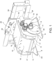
- a excavating assembly 1 for milling and/or scarifying a road surface or ground to be milled 2 comprises a support structure 3.
- Said support structure 3 delimits an internal chamber or compartment 4.
- Said support structure 3 comprises a compartment opening 5 adapted to face said road surface or ground to be milled 2.
- Said excavating assembly 1 comprises a cutter 6.
- Said cutter 6 is housed in said compartment 4 of the support structure 3 in such a way as to rotate about a cutter axis X.
- said cutter axis X is arranged in said support structure 3 so as to lie parallel to the theoretical surface of the road surface or ground to be milled 2.
- Said cutter 6 protrudes from said compartment 4 through said compartment opening 5 in order to mill said road surface or ground to be milled 2.
- Said excavating assembly 1 further comprises a cutter movement unit 7 connected to said cutter 6 and adapted to move the cutter 6.
- Said cutter movement unit 7 is supported by said support structure 3.
- Said excavating assembly 1 further comprises at least one support element 8 adapted to rest on said road surface or ground to be milled 2 during the milling operations.
- Said at least one support element 8 is separated from said support structure 3.
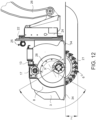
- said cutter 6 comprises a cutter axle extension 9 that protrudes from said support structure 3, thereby extending said cutter axis X.
- Said support element 8 comprises an eccentric plate seat 10.
- Said eccentric plate seat 10 rotatably houses an eccentric plate 11 so as to allow said eccentric plate 11 to rotate about a support element axis X'.
- Said eccentric plate 11 comprises a cutter axle extension seat 12.
- Said cutter axle extension seat 12 freely and rotatably houses said cutter axle extension 9. In other words, unless there are movements set by possible actuators placed between said support structure 3 and said support element 8, the support structure 3 may freely oscillate about said cutter axis X with respect to the support element 8.
- Said cutter axis X as extended by said cutter axle extension 9, is eccentric with respect to said support element axis X', defining a predetermined eccentricity e.
- Said excavating assembly 1 further comprises an eccentric plate movement unit 13 connected to said eccentric plate 11 in order to move said eccentric plate about said support element axis X'.
- said eccentric plate movement unit 13 is supported by said support structure 3 and is operatively connected to said eccentric plate 11 so as to move it inside said eccentric plate seat 10 thereof.
- said eccentric plate movement unit 13 is supported by said support structure 3 and is operatively connected to said eccentric plate 11 so as to move it inside said eccentric plate seat 10 thereof.
- Said eccentric plate movement unit 13 is connected to and actuates eccentric plate movement levers 38.
- Said eccentric plate movement levers 38 are operatively connected to said eccentric plate 11 so as to move it in the eccentric plate seat 10 thereof provided in the support element 8.
- said eccentric plate movement unit 13 is supported by said support element 8 and is operatively connected to said eccentric plate 11.
- said eccentric plate movement unit 13 comprises a linear piston-cylinder actuator or a motor connected to an internal thread and worm screw. Said cylinder, or motor and internal threads, is rotatably supported by said support element 8, and said piston, or worm screw, is rotatably connected by the end thereof to said eccentric plate 11 at a predetermined distance from the cutter axis X.
- said linear piston-cylinder actuator is a hydraulic actuator.
- said linear piston-cylinder actuator is an electric actuator, for example a motor actuating an internal thread-worm screw assembly.
- said eccentric plate movement unit 13 is supported by said support structure 3 and is operatively connected to said eccentric plate 11.
- said eccentric plate movement unit 13 comprises a linear piston-cylinder actuator.
- Said cylinder is rotatably supported by said support structure 3, and said piston is rotatably connected by the end thereof to said eccentric plate 11 at a predetermined distance from the cutter axis X.
- said linear piston-cylinder actuator is a hydraulic actuator.
- said linear piston-cylinder actuator is an electric actuator.
- said at least one support element 8 consists of two support elements 8, each comprising an eccentric plate 11 thereof, placed at opposite ends of the support structure 3. Only one eccentric plate movement unit 13 is operatively connected by means of levers and gears to both said eccentric plates 11.
- said cutter 6 comprises opposing cutter axle extensions 9 which protrude from opposite sides of said support structure 3, extending said cutter axis X on opposite sides.
- Said excavating assembly 1 further comprises two opposing support elements 8 adapted to rest on said road surface or ground to be milled 2 during the milling operations, and placed on opposite sides of said support structure 3.
- Each of said two opposing support elements 8 comprises an eccentric plate seat 10.
- Each of said eccentric plate seats 11 rotatably houses a respective eccentric plate 11 so as to allow said eccentric plate 11 to rotate about a support element axis X'.
- Each of said eccentric plates 11 comprises a cutter axle extension seat 12.
- Each of said cutter axle extension seats 12 freely and rotatably houses a respective one of said cutter axle extensions 9.
- Said cutter axis X as extended by said cutter axle extensions 9, is eccentric with respect to said support element axis X', defining a predetermined eccentricity e.
- the portion of cutter 6 that protrudes from support element 8 is increased or decreased by rotating said eccentric plate 11 in said eccentric plate seat 10.
- said cutter axis, or cutter rotation axis, X is parallel to said support element axis X'.
- said at least one support element 8 consists of two support elements 8 placed at opposite ends of the support structure 3.
- Each said support element 8 comprises an eccentric plate seat 9 which rotatably houses an eccentric plate 11 so as to allow said eccentric plate 11 to rotate about a support element axis X'; and in which said eccentric plate 11 comprises a cutter axle extension seat 11; and in which said cutter axle extension seat 11 freely and rotatably houses said cutter axle extension seat 9; and in which said cutter axis X as extended by said cutter axle extension seat 9 is eccentric with respect to said support element axis X', defining a predetermined eccentricity e; and in which said excavating assembly 1 further comprises an eccentric plate movement unit 13 supported by said support element 8 or supported by said support structure 3 and connected to said eccentric plate 11 so as to move said eccentric plate about said support element axis X'.
- said at least one support element 8 consists of two support elements 8 placed on opposite sides of the support structure 3.
- a first support element 8 comprises an eccentric plate seat 9 which rotatably houses an eccentric plate 11 so as to allow said eccentric plate 11 to rotate about a support element axis X'; and in which said eccentric plate 11 comprises a cutter axle extension seat 11; and in which said cutter axle extension seat 11 freely and rotatably houses said cutter axle extension 9; and in which said cutter axis X as extended by said cutter axle extension 9 is eccentric with respect to said support element axis X', defining a predetermined eccentricity e; and in which said excavating assembly 1 further comprises an eccentric plate movement unit 13 supported by said support element 8 or supported by said support structure 3 and connected to said eccentric plate 11 so as to move said eccentric plate about said support element axis X' .
- a second support element 8 comprises an eccentric plate seat 9 which rotatably houses an eccentric plate 11 so as to allow said eccentric plate 11 to rotate about a support element axis X' ; and in which said eccentric plate 11 comprises a cutter axle extension seat 11; and in which said cutter axle extension seat 11 freely and rotatably houses a support structure shaft 36 integrally attached to said support structure 3; and in which said cutter axis X is extended in said support structure shaft 36 and is eccentric with respect to said support element axis X', defining a predetermined eccentricity e; and in which said excavating assembly 1 further comprises an eccentric plate movement unit 13 supported by said support element 8 or supported by said support structure 3 and connected to said eccentric plate 11 so as to move said eccentric plate about said support element axis X'.
- said cutter 6 is supported by said support structure 3 at least by means of the cutter movement unit or cutter motor 7.
- said cutter axis X and the axis of the cutter movement unit or cutter motor 7 coincide with each other.
- said cutter axle extension 9 is part of the cutter movement unit 7.
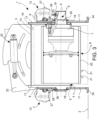
- said support structure 3 is a box structure.
- said support structure 3 is a closed box structure with the exception of said compartment opening 5 from which said cutter 6 protrudes.
- said support structure 3 is a box structure that comprises an upper plate 14, a front plate 15, a rear plate 16, and sides 17 opposite each other with respect to said cutter 6; and/or in which said sides 17 are connected by separable means to said upper plate 14, front plate 15, and rear plate 16 so that the same type of sides 17 may be used for support structures 3 having widths according to different axial extensions.
- said support structure 3 is a box structure that comprises an upper plate 14, a front plate 15, a rear plate 16, and sides 17 opposite each other with respect to said cutter 6; and in which at least one side 17 comprises a cutter support seat 18 defining a cutter axis of rotation or cutter axis X.
- said support structure 3 is a box structure which comprises an upper plate 14 with which a piece of excavating assembly service equipment, such as a tank for a fluid, is associated.
- said cutter support seat 18 is a motor seat that accommodates a portion of said cutter movement unit or cutter motor 7.
- said cutter movement unit 7 comprises said cutter axle extension 9; a portion of said cutter axle extension 9 protrudes out of the support structure 3 and comprises power supply connections 19 adapted to connected the power supply to said cutter movement unit 7.
- said cutter movement unit or cutter motor 7 comprises a hydraulic motor. According to a particular embodiment, said cutter movement unit or cutter motor 7 comprises an electric motor.
- said cutter movement unit or cutter motor 7 is completely housed inside the support structure 3.
- said cutter movement unit or cutter motor 7 is completely housed inside the support structure 3 with the exception of the extension portion of the cutter axle 9.
- said cutter movement unit or cutter motor 7 is housed inside said cutter 6. According to a particular embodiment, said cutter movement unit or cutter motor 7 is housed outside said cutter 6.
- said cutter 6 is a cutter cylinder having a cutter cover 20 which supports a plurality of cutting tools 21 in a cantilever fashion.
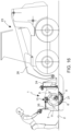
- said support structure 3 is oscillatingly connected to a connection element 22 for connection to a loading machine 23, such as a skid steer excavator or an agricultural machine or a road tractor or a self-propelled machine, for example a skid steer loader or skid loader.
- a loading machine 23 such as a skid steer excavator or an agricultural machine or a road tractor or a self-propelled machine, for example a skid steer loader or skid loader.
- said support structure 3 is oscillatingly connected to a connection element 22 for connection to a loading machine 23, for example excavator 23 with an articulated arm 26.
- connection element 22 is slidably connected to transverse translation guides 24 defining an axis of translation T.
- said axis of translation T is parallel to said cutter axis X.
- said support structure 3 is oscillatingly connected to an attachment element 22 so as to allow said excavating assembly 1 to oscillate about an axis of oscillation Zo.
- said axis of oscillation Zo is orthogonal to the cutter axis X.
- said excavating assembly 1 comprises a cutter oscillation unit 25; said cutter oscillation unit 25 is placed between a connection element 22 for connection of the excavating assembly 1 to a loading machine 23, and said support structure 3 to adjust an oscillation of the excavating assembly 1 about an axis of oscillation Zo.
- connection element 22 is arranged opposite the travel direction of the milling so that said excavating assembly 1 is placed in front of a loading machine 23 with respect to the travel direction thereof, for example for connection to a front arm 26 of a skid steer loader or skid loader 23 and to allow milling both in a forward direction and in a backward direction of said loading machine 23.
- connection element 22 is arranged in the advancing direction of the milling so that said excavating assembly 1 is placed behind a loading machine 23 with respect to the travel direction thereof, for example for connection to rear support and lifting arms of a tractor 23 and to allow milling both in a forward direction and in a backward direction of said loading machine 23.
- said eccentric plate movement unit 13 comprises a gearmotor.
- said eccentric plate movement unit 13 comprises an electric motor.
- said eccentric plate movement unit 13 comprises a hydraulic motor.
- said eccentric plate movement unit 13 comprises a gear driven by a crank 35 which may be associated therewith by separable means.
- said eccentric plate movement unit 13 comprises a pinion 27.
- Said eccentric plate 11 comprises a rack 28.
- Said pinion 27 meshes with said rack 28.
- said rack 28 is arch-shaped to control the oscillation movement of the eccentric plate 11 in said eccentric plate seat 10.
- said eccentric plate seat 10 is an open seat.
- said eccentric plate seat 10 is a closed seat.
- said eccentric plate seat 10 comprises at least one seat edge 29; said seat edge 29 accommodates and guides the oscillation of said eccentric plate 11.
- said eccentric plate 11 comprises at least one eccentric plate edge 37; said eccentric plate edge 37 is accommodated and guided by said at least one seat edge 29.
- said cutter axle extension seat 12 is an open seat.
- said cutter axle extension seat 12 is a closed seat.
- said cutter axle extension 9 comprises a motor guide 30; said cutter axle extension seat 12 is fitted to said motor guide 30.
- said motor guide 30 comprises a seat shoulder 31 and a Seeger ring seat 31; said eccentric plate 11, when fitted to said motor guide 30 of said cutter axle extension 9 with the motor seat 12 thereof, is placed between said seat shoulder 31 and a Seeger ring 33 removably received into said Seeger ring seat 31.
- said support element 8 comprises support element runners 34 adapted to rest on said road surface or ground to be milled 2.
- said excavating assembly 1 may be removably applied or secured to a vehicle, such as a skid steer loader or skid loader or excavator.
- the present invention also relates to a operating machine or operating machine or simply 23 comprising a excavating assembly 1 as described in any one of the preceding embodiments.
- said excavating assembly is removably associated with the operating or loading machine 23 at the front thereof with respect to the direction of operation of the operating or loading machine 23.
- the present invention also relates to a method for adjusting a excavating assembly 1 comprising the following steps:
Landscapes
- Engineering & Computer Science (AREA)
- Mechanical Engineering (AREA)
- Mining & Mineral Resources (AREA)
- Civil Engineering (AREA)
- Structural Engineering (AREA)
- General Engineering & Computer Science (AREA)
- Architecture (AREA)
- Road Repair (AREA)
- Road Signs Or Road Markings (AREA)
- Excavating Of Shafts Or Tunnels (AREA)
Claims (23)
- Abtragungsbaugruppe (1) zum Fräsen und/oder Aufreißen einer Straßenfläche oder eines Bodens, welcher zu fräsen ist (2), wobeidie Abtragungsbaugruppe (1) eine Stützstruktur (3) umfasst, welche einen Raum (4) begrenzt, wobei die Stützstruktur (3) eine Raumöffnung (5) umfasst, welche dazu angepasst ist, zu der Straßenfläche oder dem Boden, welcher zu fräsen ist (2), ausgerichtet zu sein;die Abtragungsbaugruppe (1) ferner einen Schneider (6) umfasst, wobei der Schneider (6) in dem Raum (4) der Stützstruktur (3) beherbergt ist, sodass er rotierbar ist um eine Schneiderachse (X); wobei der Schneider (6) aus dem Raum (4) hervorragt durch die Raumöffnung (5), um die Straßenfläche oder den Boden, der zu fräsen ist (2), zu fräsen;die Abtragungsbaugruppe (1) ferner eine Schneiderbewegungseinheit (7) umfasst, welche mit dem Schneider (6) verbunden ist; wobei die Schneiderbewegungseinheit (7) durch die Stützstruktur (3) gestützt ist;die Abtragungsbaugruppe (1) ferner wenigstens ein Stützelement (8) umfasst, welches dazu angepasst ist, auf der Straßenfläche oder dem Boden, welcher zu fräsen ist (2), während der Fräsvorgänge zu ruhen;wobei das wenigstens eine Stützelement (8) separat von der Stützstruktur (3) ist;dadurch gekennzeichnet, dassder Schneider (6) eine Schneiderwellenerweiterung (9) umfasst, welche von der Stützstruktur (3) hervorsteht, sodass sie die Schneiderachse (X) erweitert;das Stützelement (8) einen exzentrischen Plattensitz (10) umfasst;der exzentrische Plattensitz (10) eine exzentrische Platte (11) rotierbar beherbergt, um zuzulassen, dass die exzentrische Platte (11) um eine Stützelementachse (X`) rotiert;die exzentrische Platte (11) einen Schneiderwellenerweiterungssitz (12) umfasst;der Schneiderwellenerweiterungssitz (12) die Schneiderwellenerweiterung (9) beherbergt, sodass diese frei rotierbar ist;die Schneiderachse (X), indem sie durch die Schneiderwellenerweiterung (9) erweitert ist, exzentrisch ist in Bezug auf die Stützelementachse (X`), wobei sie eine vorbestimmte Exzentrizität (e) definiert;die Abtragungsbaugruppe (1) ferner eine Bewegungseinheit der exzentrischen Platte (13) umfasst, welche mit der exzentrischen Platte (11) verbunden ist, um die exzentrische Platte um die Stützelementachse (X`) zu bewegen.
- Abtragungsbaugruppe (1) nach Anspruch 1, wobei
eine der folgenden Optionen bereitgestellt ist:die Bewegungseinheit der exzentrischen Platte (13) stützt die Stützstruktur (3) und ist operativ mit der exzentrischen Platte (11) verbunden, um diese in dem exzentrischen Plattensitz (10) davon zu bewegen;
oderdie Bewegungseinheit der exzentrischen Platte (13) stützt die Stützstruktur (3) und ist operativ mit der exzentrischen Platte (11) verbunden, um diese in dem exzentrischen Plattensitz (10) davon zu bewegen; die Bewegungseinheit der exzentrischen Platte (13) ist verbunden und treibt exzentrische Plattenbewegungshebel (38) an; die exzentrischen Plattenbewegungshebel (38) sind operativ mit der exzentrischen Platte (11) verbunden, um sie in dem exzentrischen Plattensitz (10) davon zu bewegen, welcher in dem Stützelement (8) bereitgestellt ist;
oderdie Bewegungseinheit der exzentrischen Platte (13) stützt das Stützelement (8) und ist operativ mit der exzentrischen Platte (11) verbunden;
oderdie Bewegungseinheit der exzentrischen Platte (13) umfasst einen linearen Kolbenzylinderantreiber oder einen Motor, welcher mit einem inneren Gewinde und einer Schneckenschraube verbunden ist; wobei der Zylinder oder der Motor und das interne Gewinde rotierbar gestützt sind durch das Stützelement (8) und der Kolben oder die Schneckenschraube mit dem Ende davon rotierbar mit der exzentrischen Platte (11) an einer vorbestimmten Distanz von der Schneiderachse (X) verbunden ist; und/oder wobei der lineare Kolbenzylinderantreiber ein hydraulischer Antreiber ist, und/oder wobei der lineare Kolbenzylinderantreiber ein elektrischer Antreiber ist, zum Beispiel ein Motor, welcher die Innengewinde-Schneckenschraube antreibt;
oderdie Bewegungseinheit der exzentrischen Platte (13) ist durch die Stützstruktur (3) gestützt und ist operativ mit der exzentrischen Platte (11) verbunden;
oderdie Bewegungseinheit der exzentrischen Platte (13) umfasst einen linearen Kolbenzylinderantreiber; wobei der Zylinder rotierbar durch die Stützstruktur (3) gestützt ist und der Kolben rotierbar mit dem Ende davon mit der exzentrischen Platte (11) an einer vorbestimmten Entfernung von der Schneiderachse (X) verbunden ist; und/oder wobei der lineare Kolbenzylinderantreiber ein hydraulischer Antreiber ist; und/oder wobei der lineare Kolbenzylinderantreiber ein elektrischer Antreiber ist. - Abtragungsbaugruppe (1) nach einem der vorhergehenden Ansprüche, wobeider Schneider (6) entgegengesetzte Schneiderwellenerweiterungen (9) umfasst, welche an entgegengesetzten Seiten von der Stützstruktur (3) hervorragen, sodass sie, an entgegengesetzten Seiten, die Schneiderachse (X) erweitern;die Abtragungsbaugruppe (1) ferner zwei entgegengesetzte Stützelemente (8) umfasst, welche dazu angepasst sind, auf der Straßenfläche oder dem Boden, welcher zu fräsen ist (2), während der Fräsvorgänge zu ruhen und an entgegengesetzten Seiten der Stützstruktur (3) angeordnet zu sein;jedes der zwei entgegengesetzten Stützelemente (8) einen exzentrischen Plattensitz (10) umfasst;jeder der exzentrischen Plattensitze (10) eine entsprechende exzentrische Platte (11) rotierbar beherbergt, um zuzulassen, dass die exzentrische Platte (11) um eine Stützelementachse (X`) rotiert;jede der beiden exzentrischen Platten (11) einen Schneiderwellenerweiterungssitz (12) umfasst;jeder der Schneiderwellenerweiterungssitze (12) eine entsprechende der Schneiderwellenerweiterungen (9) beherbergt, sodass diese frei rotierbar ist;die Schneiderachse (X), indem sie durch die Schneiderwellenerweiterungen (9) erweitert ist, exzentrisch ist in Bezug auf die Stützelementachse (X`), sodass sie eine vorbestimmte Exzentrizität (e) definiert;und wobei eine der folgenden Alternativen bereitgestellt ist:- die Abtragungsbaugruppe (1) umfasst ferner eine Bewegungseinheit der exzentrischen Platte (13), welche mit den exzentrischen Platten (11) verbunden ist, um die exzentrischen Platten um die Stützelementachse (X`) zu bewegen; oder- die Abtragungsbaugruppe (1) umfasst ferner zwei Bewegungseinheiten der exzentrischen Platte (13), welche jeweils mit einer entsprechenden der exzentrischen Platten (11) verbunden ist, um die exzentrische Platte (11) um die Stützelementachse (X`) zu bewegen.
- Abtragungsbaugruppe (1) nach einem der vorherigen Ansprüche, wobeidas wenigstens eine Stützelement (8) aus zwei Stützelementen (8) besteht, welche an entgegengesetzten Seiten der Stützstruktur (3) angeordnet sind;
und wobeijedes der Stützelemente (8) einen exzentrischen Plattensitz (9) umfasst, welcher eine exzentrische Platte (11) rotierbar beherbergt, um zuzulassen, dass die exzentrische Platte (11) um eine Stützelementachse (X`) rotiert; und wobei die exzentrische Platte (11) einen Schneiderwellenerweiterungssitz (11) umfasst; und wobei der Schneiderwellenerweiterungssitz (11) die Schneiderwellenerweiterung (9) beherbergt, sodass diese frei rotierbar ist; und wobei die Schneiderachse (X), indem sie durch die Schneiderwellenerweiterung (9) erweitert ist, exzentrisch in Bezug zu der Stützelementachse (X`) ist, sodass sie eine vorbestimmte Exzentrizität (e) definiert; und wobei die Abtragungsbaugruppe (1) ferner eine Bewegungseinheit der exzentrischen Platte (13) umfasst, welche durch das Stützelement (8) gestützt ist, oder durch die Stützstruktur (3) gestützt ist und mit der exzentrischen Platte (11) verbunden ist, um die exzentrische Platte um die Stützelementachse (X`) zu bewegen. - Abtragungsbaugruppe (1) nach einem der vorhergehenden Ansprüche, wobeidas wenigstens eine Stützelement (8) aus zwei Stützelementen (8) besteht, welche an entgegengesetzten Seiten der Stützstruktur (3) angeordnet sind;
und wobeiein erstes Stützelement (8) einen exzentrischen Plattensitz (9) umfasst, welcher eine exzentrische Platte (11) rotierbar beherbergt, um zuzulassen, dass die exzentrische Platte (11) um eine Stützelementachse (X`) rotiert; und wobei die exzentrische Platte (11) einen Schneiderwellenerweiterungssitz (11) umfasst; und wobei der Schneiderwellenerweiterungssitz (11) die Schneiderwellenerweiterung (9) beherbergt, sodass diese frei rotierbar ist; und wobei die Schneiderachse (X), indem sie durch die Schneiderwellenerweiterung (9) erweitert ist, exzentrisch in Bezug auf die Stützelementachse (X`) ist, sodass sie eine vorbestimmte Exzentrizität (e) definiert; und wobei die Abtragungsbaugruppe (1) ferner eine Bewegungseinheit der exzentrischen Platte (13) umfasst, welche durch das Stützelement (8) gestützt ist oder durch die Stützstruktur (3) gestützt ist und mit der exzentrischen Platte (11) verbunden ist, um die exzentrische Platte um die Stützelementachse (X') zu bewegen; und wobeiein zweites Stützelement (8) einen exzentrischen Plattensitz (9) umfasst, welcher eine exzentrische Platte (11) rotierbar beherbergt, um zuzulassen, dass die exzentrische Platte (11) um eine Stützelementachse (X') rotiert; und wobei die exzentrische Platte (11) einen Schneiderwellenerweiterungssitz (11) umfasst; und wobei der Schneiderwellenerweiterungssitz (11) einen Stützstrukturschaft (36) umfasst, welcher integral an der Stützstruktur (3) fixiert ist, sodass er frei rotierbar ist; und wobei die Schneiderachse (X) sich in den Stützstrukturschaft (36) erstreckt und exzentrisch in Bezug zu der Stützelementachse (X`) ist, sodass sie eine vorbestimmte Exzentrizität (e) definiert; und wobei die Abtragungsbaugruppe (1) ferner eine Bewegungseinheit der exzentrischen Platte (13) umfasst, welche durch das Stützelement (8) gestützt ist oder durch die Stützstruktur (3) gestützt ist und mit der exzentrischen Platte (11) verbunden ist, um die exzentrische Platte um die Stützelementachse (X`) zu bewegen. - Abtragungsbaugruppe (1) nach einem der vorhergehenden Ansprüche, wobeidie Stützstruktur (3) eine Kistenstruktur ist, welche eine Deckplatte (14), eine Frontplatte (15) eine Rückplatte (16) und Seiten (17) umfasst, welche entgegengesetzt zueinander in Bezug zu dem Schneider (6) sind; und/oder wobei die Seiten (17) trennbar mit der Deckplatte (14), der Frontplatte (15) und der Rückplatte (16) verbunden sind, um zuzulassen, dass der gleiche Typ von Seiten (17) für die Stützstrukturen (3) verwendet wird mit einer verschiedenen Stärke entsprechend der axialen Erstreckung;
oderdie Stützstruktur (3) eine Kistenstruktur ist, welche eine Deckplatte (14), eine Frontplatte (15) eine Rückplatte (16) und Seiten (17) umfasst, welche entgegengesetzt zueinander in Bezug zu dem Schneider (6) sind; und wobei wenigstens eine Seite (17) einen Schneiderstützsitz (18) umfasst, welcher eine Schneiderachse einer Rotation oder eine Schneiderachse (X) definiert. - Abtragungsbaugruppe (1) nach einem der vorhergehenden Ansprüche, wobei
die Stützstruktur (3) eine Kistenstruktur ist, welche eine Deckplatte (14) umfasst, mit welcher eine Betriebsvorrichtung für die Abtragungsbaugruppe assoziiert ist, wie zum Beispiel ein Tank für ein Fluid. - Abtragungsbaugruppe (1) nach einem der Ansprüche 6 oder 7, wobei
der Schneiderstützsitz (18) ein Motorsitzt ist, welcher einen Abschnitt der Schneiderbewegungseinheit oder des Schneidermotors (7) beherbergt. - Abtragungsbaugruppe (1) nach einem der vorhergehenden Ansprüche, wobei
die Schneiderbewegungseinheit oder der Schneidermotor (7) vollständig in der Stützstruktur (3) beherbergt ist abgesehen von dem Schneiderwellenerweiterungsabschnitt (9). - Abtragungsbaugruppe (1) nach einem der vorhergehenden Ansprüche, wobei
die Stützstruktur (3) oszillierend mit einem Verbindungselement (22) verbunden ist für eine Verbindung mit einer Arbeitsmaschine (23), wie zum Beispiel einem Kompaktbagger oder einer landwirtschaftlichen Maschine oder einem Straßentraktor oder einer selbstfahrenden Maschine, wie zum Beispiel einem Kompaktlader oder einem Kompaktlader. - Abtragungsbaugruppe (1) nach einem der vorhergehenden Ansprüche, wobei
die Stützstruktur (3) oszillierend mit einem Verbindungselement (22) verbunden ist für eine Verbindung mit einer Arbeitsmaschine (23), wie zum Beispiel einem Gelenkarmbagger. - Abtragungsbaugruppe (1) nach dem vorhergehenden Anspruch, wobei das Verbindungselement (22) verschiebbar mit querlaufenden Schiebeführungen (24) verbunden ist, welche eine Schiebeachse (T) definieren.
- Abtragungsbaugruppe (1) nach Anspruch 12, wobei
die Schiebeachse (T) parallel zu der Schneiderachse (X) ist. - Abtragungsbaugruppe (1) nach einem der vorhergehenden Ansprüche, wobei
die Stützstruktur (3) oszillierend mit einem Verbindungselement (22) verbunden ist, um zuzulassen, dass die Abtragungsbaugruppe (1) um eine Oszillationsachse (Zo) oszilliert. - Abtragungsbaugruppe (1) nach einem der vorhergehenden Ansprüche, wobei
die Abtragungsbaugruppe (1) eine Schneideroszillationseinheit (25) umfasst; die Schneideroszillationseinheit (25) zwischen einem Verbindungselement (22) zum Verbinden der Abtragungsbaugruppe (1) mit einer Arbeitsmaschine (23) und der Stützstruktur (3) angeordnet ist, um eine Oszillation der Abtragungsbaugruppe (1) um eine Oszillationsachse (Zo) einzustellen. - Abtragungsbaugruppe (1) nach dem vorhergehenden Anspruch, wobei
das Verbindungselement (22) entgegengesetzt zur Fräsrichtung angeordnet ist, sodass die Abtragungsbaugruppe (1) vor einer Arbeitsmaschine (23) in Bezug auf die Bewegungsrichtung davon angeordnet ist, zum Beispiel zur Verbindung mit einem Frontausleger (26) eines Kompaktladers oder Kompaktladers (23), und um Fräsen sowohl in eine Vorwärtsrichtung als auch in eine Rückwärtsrichtung der Arbeitsmaschine (23) zuzulassen. - Abtragungsbaugruppe (1) nach einem der Ansprüche 15 oder 16, wobei
das Verbindungselement (22) in der Fräsrichtung angeordnet ist, sodass die Abtragungsbaugruppe (1) hinter einer Arbeitsmaschine (23) in Bezug auf die Bewegungsrichtung davon angeordnet ist, zum Beispiel zur hinteren Verbindung mit hinteren Stütz- und Hebearmen eines Traktors (23) und um Fräsen sowohl in eine Vorwärtsrichtung als auch in eine Rückwärtsrichtung der Arbeitsmaschine (23) zuzulassen. - Abtragungsbaugruppe (1) nach dem vorhergehenden Anspruch, wobeidie Motorführung (30) eine Sitzschulter (31) und einen Seeger-Ringsitz (31) umfasst; und wobeidie exzentrische Platte (11), wenn der Motorsitz (12) davon auf die Motorführung (30) der Schneiderwellenerweiterung (9) angepasst ist, zwischen der Sitzschulter (31) und einem Seeger-Ring (33) angeordnet ist, welcher entfernbar in dem Seeger-Ringsitz (31) aufgenommen ist.
- Abtragungsbaugruppe (1) nach einem der vorhergehenden Ansprüche, wobei
das Stützelement (8) Stützelementkufen (34) umfasst, welche dazu angepasst sind, auf der Straßenfläche oder dem Boden, welcher zu fräsen ist (2), zu ruhen. - Baugruppe umfassend eine arbeitende oder Arbeitsmaschine (23), welche eine Abtragungsbaugruppe (1) umfasst, wie in einem der vorgehenden Ansprüche definiert.
- Verfahren zum Einstellen einer Abtragungsbaugruppe umfassend die Schritte zum• Bereitstellen einer Abtragungsbaugruppe nach einem der Ansprüche 1 bis 19;• Bewegen der exzentrischen Platte (11) in dem exzentrischen Plattensitz (10), um die exzentrische Ausrichtung der Schneiderachse (X) in Bezug auf die Stützelementachse (X`) zu bewegen, sodass die Exzentrizität (e) versetzt wird, vergrößern oder verkleinern des Schneiderabschnitts (6), welcher von dem Stützelement (8) vorragt, und Ändern der Schneidtiefe (z), wenn die Abtragungsbaugruppe gegen die Straßenfläche oder den Boden, welcher zu fräsen ist (2), gepresst wird.
- Verfahren zum Einstellen einer Abtragungsbaugruppe nach Anspruch 21, umfassend weitere Schritte zum:
Unabhängigen Bewegen jeder exzentrischen Platte (11) von jedem entgegengesetzten Stützelement (8). - Verfahren zum Einstellen einer Abtragungsbaugruppe nach Anspruch 21, umfassend weitere Schritte zum:Freien Oszillieren der Stützstruktur (3) in Bezug auf das Stützelement (8) zumAnpassen des Winkels zwischen der Stützstruktur (3) und der Straßenfläche oder dem Boden, welcher zu fräsen ist (2);
oder zumAnpassen des Winkels des Verbindungselements (22) in Bezug auf die Straßenfläche oder den Boden, welcher zu fräsen ist (2).
Applications Claiming Priority (2)
| Application Number | Priority Date | Filing Date | Title |
|---|---|---|---|
| IT102020000025711A IT202000025711A1 (it) | 2020-10-29 | 2020-10-29 | Assieme di fresa per fresare un manto stradale o suolo |
| PCT/IB2021/059979 WO2022090993A1 (en) | 2020-10-29 | 2021-10-28 | A excavating assembly for milling a road surface or ground |
Publications (3)
| Publication Number | Publication Date |
|---|---|
| EP4237622A1 EP4237622A1 (de) | 2023-09-06 |
| EP4237622C0 EP4237622C0 (de) | 2024-10-02 |
| EP4237622B1 true EP4237622B1 (de) | 2024-10-02 |
Family
ID=74194853
Family Applications (1)
| Application Number | Title | Priority Date | Filing Date |
|---|---|---|---|
| EP21810727.4A Active EP4237622B1 (de) | 2020-10-29 | 2021-10-28 | Ausgrabanordnung zum fräsen einer strassenoberfläche oder eines bodens |
Country Status (5)
| Country | Link |
|---|---|
| US (1) | US12565743B2 (de) |
| EP (1) | EP4237622B1 (de) |
| AU (1) | AU2021368611B2 (de) |
| IT (1) | IT202000025711A1 (de) |
| WO (1) | WO2022090993A1 (de) |
Families Citing this family (1)
| Publication number | Priority date | Publication date | Assignee | Title |
|---|---|---|---|---|
| WO2026041941A1 (en) | 2024-08-23 | 2026-02-26 | Simex Engineering S.R.L. | Excavation accessory with hybrid actuation milling assembly |
Family Cites Families (12)
| Publication number | Priority date | Publication date | Assignee | Title |
|---|---|---|---|---|
| DE3871478D1 (de) | 1987-10-02 | 1992-07-02 | Franz Broehl | An ein fahrbares tragwerk anbaubare fraese. |
| US4878713A (en) | 1988-12-09 | 1989-11-07 | Alitec Corporation | Pavement planing machine |
| US5864970A (en) | 1996-01-22 | 1999-02-02 | Maddock; David C. | Earth excavating apparatus |
| IT1311091B1 (it) | 1999-10-05 | 2002-02-28 | Simex Engineering S R L | Attrezzatura per macchine di movimentazione terra, edili, stradali esemoventi in genere, per fresare e per scarificare il manto stradale, |
| US20020195869A1 (en) | 2001-06-25 | 2002-12-26 | Dybsetter Eric D. | Single arm support apparatus for a rockwheel |
| US7665806B2 (en) * | 2006-06-13 | 2010-02-23 | Volvo Construction Equipment Ab | Containment wall closure device for milling machine cutter drum assembly |
| GB2470326B (en) * | 2008-03-11 | 2012-10-31 | Coneqtec Corp | Adjustable planer system |
| ITBO20110097A1 (it) * | 2011-03-01 | 2012-09-02 | Simex Srl | Apparecchiatura per la lavorazione e in particolare per la demolizione e/o fresatura di superfici orizzontali , verticali o inclinate con scavo senza gradini |
| DE202012104064U1 (de) * | 2012-10-23 | 2013-03-06 | Stehr Baumaschinen Gmbh | Fahrbares und/oder an ein Trägerfahrzeug anbaubares Bodenbearbeitungsgerät |
| EP2735654B1 (de) | 2012-11-27 | 2015-07-29 | Lasse Jaakkola | Radgrabvorrichtung zum Verlegen von Kabeln in den Boden |
| GB2512945B (en) | 2013-04-13 | 2015-08-26 | Auger Torque Europ Ltd | Ground planer |
| IT201600119002A1 (it) * | 2016-11-24 | 2018-05-24 | Simex Eng S R L | Apparecchiatura per la lavorazione di superfici, in particolare di superfici solide, in particolare per la realizzazione di bande sonore |
-
2020
- 2020-10-29 IT IT102020000025711A patent/IT202000025711A1/it unknown
-
2021
- 2021-10-28 WO PCT/IB2021/059979 patent/WO2022090993A1/en not_active Ceased
- 2021-10-28 EP EP21810727.4A patent/EP4237622B1/de active Active
- 2021-10-28 US US18/034,337 patent/US12565743B2/en active Active
- 2021-10-28 AU AU2021368611A patent/AU2021368611B2/en active Active
Also Published As
| Publication number | Publication date |
|---|---|
| AU2021368611B2 (en) | 2026-01-29 |
| EP4237622C0 (de) | 2024-10-02 |
| US20230392328A1 (en) | 2023-12-07 |
| WO2022090993A1 (en) | 2022-05-05 |
| AU2021368611A1 (en) | 2023-06-08 |
| IT202000025711A1 (it) | 2022-04-29 |
| EP4237622A1 (de) | 2023-09-06 |
| US12565743B2 (en) | 2026-03-03 |
Similar Documents
| Publication | Publication Date | Title |
|---|---|---|
| DE69928608T2 (de) | Fräse mit Randfräsmöglichkeit | |
| JP7560522B2 (ja) | 路面切削用の自走式道路切削機、特に大型切削機、および路面切削の方法 | |
| US11396734B2 (en) | Trenching system with hydraulically adjustable hub | |
| US5203615A (en) | Full side shift system for detachable rotary apparatus | |
| US4878713A (en) | Pavement planing machine | |
| EP2456925B1 (de) | Grabensystem | |
| EP2205060B1 (de) | Baumstumpffräse | |
| US6071066A (en) | Backhoe elevator with telescopic arm | |
| US6135567A (en) | Rotatable implement depth control apparatus | |
| EP4237622B1 (de) | Ausgrabanordnung zum fräsen einer strassenoberfläche oder eines bodens | |
| WO2000037887A2 (en) | Rotatable implement depth control apparatus | |
| EP2122069B1 (de) | Terrain-bearbeitungsmaschine | |
| EP1773557B1 (de) | Führungsantriebseinstellung für eine betonsäge | |
| US20230243114A1 (en) | Ride-On Roadway Maintenance Machine | |
| US4043402A (en) | Soil stabilizer machine with detachable hydraulic motor structure driving rotatably mounted cutting elements | |
| US11230820B2 (en) | Circle drive system for a grading machine | |
| CN117587684A (zh) | 铣刨附件 | |
| EP3916157B1 (de) | Arbeitsmaschinen und verfahren zum entfernen von material von einer zu reparierenden oberfläche mit einer solchen arbeitsmaschine | |
| DE4016485C2 (de) | Gesteinsschlitzmaschine | |
| EP4324985B1 (de) | Fräsaufsatz mit verstellbarer abdeckung | |
| US3795279A (en) | Self-propelled soil stabilizer machine | |
| US4162087A (en) | Self-propelled translatable working unit for tractor vehicle | |
| US3907038A (en) | Self-propelled soil stabilizer machine | |
| DE2357559C3 (de) | Walzenschrämmaschine mit stirnseitig angeordneter Brechwalze | |
| US3865195A (en) | Self-propelled soil stabilizer machine |
Legal Events
| Date | Code | Title | Description |
|---|---|---|---|
| STAA | Information on the status of an ep patent application or granted ep patent |
Free format text: STATUS: UNKNOWN |
|
| STAA | Information on the status of an ep patent application or granted ep patent |
Free format text: STATUS: THE INTERNATIONAL PUBLICATION HAS BEEN MADE |
|
| PUAI | Public reference made under article 153(3) epc to a published international application that has entered the european phase |
Free format text: ORIGINAL CODE: 0009012 |
|
| STAA | Information on the status of an ep patent application or granted ep patent |
Free format text: STATUS: REQUEST FOR EXAMINATION WAS MADE |
|
| 17P | Request for examination filed |
Effective date: 20230418 |
|
| AK | Designated contracting states |
Kind code of ref document: A1 Designated state(s): AL AT BE BG CH CY CZ DE DK EE ES FI FR GB GR HR HU IE IS IT LI LT LU LV MC MK MT NL NO PL PT RO RS SE SI SK SM TR |
|
| DAV | Request for validation of the european patent (deleted) | ||
| DAX | Request for extension of the european patent (deleted) | ||
| GRAP | Despatch of communication of intention to grant a patent |
Free format text: ORIGINAL CODE: EPIDOSNIGR1 |
|
| STAA | Information on the status of an ep patent application or granted ep patent |
Free format text: STATUS: GRANT OF PATENT IS INTENDED |
|
| INTG | Intention to grant announced |
Effective date: 20240426 |
|
| GRAS | Grant fee paid |
Free format text: ORIGINAL CODE: EPIDOSNIGR3 |
|
| GRAA | (expected) grant |
Free format text: ORIGINAL CODE: 0009210 |
|
| STAA | Information on the status of an ep patent application or granted ep patent |
Free format text: STATUS: THE PATENT HAS BEEN GRANTED |
|
| AK | Designated contracting states |
Kind code of ref document: B1 Designated state(s): AL AT BE BG CH CY CZ DE DK EE ES FI FR GB GR HR HU IE IS IT LI LT LU LV MC MK MT NL NO PL PT RO RS SE SI SK SM TR |
|
| REG | Reference to a national code |
Ref country code: GB Ref legal event code: FG4D |
|
| REG | Reference to a national code |
Ref country code: CH Ref legal event code: EP |
|
| REG | Reference to a national code |
Ref country code: IE Ref legal event code: FG4D |
|
| REG | Reference to a national code |
Ref country code: DE Ref legal event code: R096 Ref document number: 602021019688 Country of ref document: DE |
|
| U01 | Request for unitary effect filed |
Effective date: 20241018 |
|
| U07 | Unitary effect registered |
Designated state(s): AT BE BG DE DK EE FI FR IT LT LU LV MT NL PT RO SE SI Effective date: 20241106 |
|
| U20 | Renewal fee for the european patent with unitary effect paid |
Year of fee payment: 4 Effective date: 20241121 |
|
| PG25 | Lapsed in a contracting state [announced via postgrant information from national office to epo] |
Ref country code: HR Free format text: LAPSE BECAUSE OF FAILURE TO SUBMIT A TRANSLATION OF THE DESCRIPTION OR TO PAY THE FEE WITHIN THE PRESCRIBED TIME-LIMIT Effective date: 20241002 Ref country code: IS Free format text: LAPSE BECAUSE OF FAILURE TO SUBMIT A TRANSLATION OF THE DESCRIPTION OR TO PAY THE FEE WITHIN THE PRESCRIBED TIME-LIMIT Effective date: 20250202 |
|
| PG25 | Lapsed in a contracting state [announced via postgrant information from national office to epo] |
Ref country code: ES Free format text: LAPSE BECAUSE OF FAILURE TO SUBMIT A TRANSLATION OF THE DESCRIPTION OR TO PAY THE FEE WITHIN THE PRESCRIBED TIME-LIMIT Effective date: 20241002 |
|
| PG25 | Lapsed in a contracting state [announced via postgrant information from national office to epo] |
Ref country code: NO Free format text: LAPSE BECAUSE OF FAILURE TO SUBMIT A TRANSLATION OF THE DESCRIPTION OR TO PAY THE FEE WITHIN THE PRESCRIBED TIME-LIMIT Effective date: 20250102 |
|
| PG25 | Lapsed in a contracting state [announced via postgrant information from national office to epo] |
Ref country code: GR Free format text: LAPSE BECAUSE OF FAILURE TO SUBMIT A TRANSLATION OF THE DESCRIPTION OR TO PAY THE FEE WITHIN THE PRESCRIBED TIME-LIMIT Effective date: 20250103 |
|
| PG25 | Lapsed in a contracting state [announced via postgrant information from national office to epo] |
Ref country code: PL Free format text: LAPSE BECAUSE OF FAILURE TO SUBMIT A TRANSLATION OF THE DESCRIPTION OR TO PAY THE FEE WITHIN THE PRESCRIBED TIME-LIMIT Effective date: 20241002 Ref country code: CZ Free format text: LAPSE BECAUSE OF FAILURE TO SUBMIT A TRANSLATION OF THE DESCRIPTION OR TO PAY THE FEE WITHIN THE PRESCRIBED TIME-LIMIT Effective date: 20241002 |
|
| PG25 | Lapsed in a contracting state [announced via postgrant information from national office to epo] |
Ref country code: RS Free format text: LAPSE BECAUSE OF FAILURE TO SUBMIT A TRANSLATION OF THE DESCRIPTION OR TO PAY THE FEE WITHIN THE PRESCRIBED TIME-LIMIT Effective date: 20250102 |
|
| REG | Reference to a national code |
Ref country code: CH Ref legal event code: PL |
|
| PG25 | Lapsed in a contracting state [announced via postgrant information from national office to epo] |
Ref country code: SM Free format text: LAPSE BECAUSE OF FAILURE TO SUBMIT A TRANSLATION OF THE DESCRIPTION OR TO PAY THE FEE WITHIN THE PRESCRIBED TIME-LIMIT Effective date: 20241002 |
|
| PG25 | Lapsed in a contracting state [announced via postgrant information from national office to epo] |
Ref country code: MC Free format text: LAPSE BECAUSE OF FAILURE TO SUBMIT A TRANSLATION OF THE DESCRIPTION OR TO PAY THE FEE WITHIN THE PRESCRIBED TIME-LIMIT Effective date: 20241002 |
|
| PG25 | Lapsed in a contracting state [announced via postgrant information from national office to epo] |
Ref country code: CH Free format text: LAPSE BECAUSE OF NON-PAYMENT OF DUE FEES Effective date: 20241031 |
|
| PG25 | Lapsed in a contracting state [announced via postgrant information from national office to epo] |
Ref country code: SK Free format text: LAPSE BECAUSE OF FAILURE TO SUBMIT A TRANSLATION OF THE DESCRIPTION OR TO PAY THE FEE WITHIN THE PRESCRIBED TIME-LIMIT Effective date: 20241002 |
|
| PLBE | No opposition filed within time limit |
Free format text: ORIGINAL CODE: 0009261 |
|
| STAA | Information on the status of an ep patent application or granted ep patent |
Free format text: STATUS: NO OPPOSITION FILED WITHIN TIME LIMIT |
|
| 26N | No opposition filed |
Effective date: 20250703 |
|
| U20 | Renewal fee for the european patent with unitary effect paid |
Year of fee payment: 5 Effective date: 20250825 |
|
| PG25 | Lapsed in a contracting state [announced via postgrant information from national office to epo] |
Ref country code: IE Free format text: LAPSE BECAUSE OF NON-PAYMENT OF DUE FEES Effective date: 20241028 |
|
| PG25 | Lapsed in a contracting state [announced via postgrant information from national office to epo] |
Ref country code: HU Free format text: LAPSE BECAUSE OF FAILURE TO SUBMIT A TRANSLATION OF THE DESCRIPTION OR TO PAY THE FEE WITHIN THE PRESCRIBED TIME-LIMIT; INVALID AB INITIO Effective date: 20211028 |
|
| PG25 | Lapsed in a contracting state [announced via postgrant information from national office to epo] |
Ref country code: CY Free format text: LAPSE BECAUSE OF FAILURE TO SUBMIT A TRANSLATION OF THE DESCRIPTION OR TO PAY THE FEE WITHIN THE PRESCRIBED TIME-LIMIT; INVALID AB INITIO Effective date: 20211028 |