EP4237033B1 - Oxygenator of organic fluids - Google Patents
Oxygenator of organic fluids Download PDFInfo
- Publication number
- EP4237033B1 EP4237033B1 EP21811527.7A EP21811527A EP4237033B1 EP 4237033 B1 EP4237033 B1 EP 4237033B1 EP 21811527 A EP21811527 A EP 21811527A EP 4237033 B1 EP4237033 B1 EP 4237033B1
- Authority
- EP
- European Patent Office
- Prior art keywords
- oxygenator
- sheets
- threads
- sheet
- capillary fibers
- Prior art date
- Legal status (The legal status is an assumption and is not a legal conclusion. Google has not performed a legal analysis and makes no representation as to the accuracy of the status listed.)
- Active
Links
Images


Classifications
-
- A—HUMAN NECESSITIES
- A61—MEDICAL OR VETERINARY SCIENCE; HYGIENE
- A61M—DEVICES FOR INTRODUCING MEDIA INTO, OR ONTO, THE BODY; DEVICES FOR TRANSDUCING BODY MEDIA OR FOR TAKING MEDIA FROM THE BODY; DEVICES FOR PRODUCING OR ENDING SLEEP OR STUPOR
- A61M1/00—Suction or pumping devices for medical purposes; Devices for carrying-off, for treatment of, or for carrying-over, body-liquids; Drainage systems
- A61M1/14—Dialysis systems; Artificial kidneys; Blood oxygenators ; Reciprocating systems for treatment of body fluids, e.g. single needle systems for hemofiltration or pheresis
- A61M1/16—Dialysis systems; Artificial kidneys; Blood oxygenators ; Reciprocating systems for treatment of body fluids, e.g. single needle systems for hemofiltration or pheresis with membranes
- A61M1/1621—Constructional aspects thereof
- A61M1/1623—Disposition or location of membranes relative to fluids
- A61M1/1625—Dialyser of the outside perfusion type, i.e. blood flow outside hollow membrane fibres or tubes
-
- A—HUMAN NECESSITIES
- A61—MEDICAL OR VETERINARY SCIENCE; HYGIENE
- A61M—DEVICES FOR INTRODUCING MEDIA INTO, OR ONTO, THE BODY; DEVICES FOR TRANSDUCING BODY MEDIA OR FOR TAKING MEDIA FROM THE BODY; DEVICES FOR PRODUCING OR ENDING SLEEP OR STUPOR
- A61M1/00—Suction or pumping devices for medical purposes; Devices for carrying-off, for treatment of, or for carrying-over, body-liquids; Drainage systems
- A61M1/14—Dialysis systems; Artificial kidneys; Blood oxygenators ; Reciprocating systems for treatment of body fluids, e.g. single needle systems for hemofiltration or pheresis
- A61M1/16—Dialysis systems; Artificial kidneys; Blood oxygenators ; Reciprocating systems for treatment of body fluids, e.g. single needle systems for hemofiltration or pheresis with membranes
- A61M1/1698—Blood oxygenators with or without heat-exchangers
-
- B—PERFORMING OPERATIONS; TRANSPORTING
- B01—PHYSICAL OR CHEMICAL PROCESSES OR APPARATUS IN GENERAL
- B01D—SEPARATION
- B01D63/00—Apparatus in general for separation processes using semi-permeable membranes
- B01D63/02—Hollow fibre modules
-
- B—PERFORMING OPERATIONS; TRANSPORTING
- B01—PHYSICAL OR CHEMICAL PROCESSES OR APPARATUS IN GENERAL
- B01D—SEPARATION
- B01D63/00—Apparatus in general for separation processes using semi-permeable membranes
- B01D63/02—Hollow fibre modules
- B01D63/021—Manufacturing thereof
- B01D63/022—Encapsulating hollow fibres
- B01D63/023—Encapsulating materials
-
- B—PERFORMING OPERATIONS; TRANSPORTING
- B01—PHYSICAL OR CHEMICAL PROCESSES OR APPARATUS IN GENERAL
- B01D—SEPARATION
- B01D63/00—Apparatus in general for separation processes using semi-permeable membranes
- B01D63/02—Hollow fibre modules
- B01D63/021—Manufacturing thereof
- B01D63/0232—Manufacturing thereof using hollow fibers mats as precursor, e.g. wound or pleated mats
-
- A—HUMAN NECESSITIES
- A61—MEDICAL OR VETERINARY SCIENCE; HYGIENE
- A61M—DEVICES FOR INTRODUCING MEDIA INTO, OR ONTO, THE BODY; DEVICES FOR TRANSDUCING BODY MEDIA OR FOR TAKING MEDIA FROM THE BODY; DEVICES FOR PRODUCING OR ENDING SLEEP OR STUPOR
- A61M2202/00—Special media to be introduced, removed or treated
- A61M2202/0007—Special media to be introduced, removed or treated introduced into the body
-
- A—HUMAN NECESSITIES
- A61—MEDICAL OR VETERINARY SCIENCE; HYGIENE
- A61M—DEVICES FOR INTRODUCING MEDIA INTO, OR ONTO, THE BODY; DEVICES FOR TRANSDUCING BODY MEDIA OR FOR TAKING MEDIA FROM THE BODY; DEVICES FOR PRODUCING OR ENDING SLEEP OR STUPOR
- A61M2202/00—Special media to be introduced, removed or treated
- A61M2202/0014—Special media to be introduced, removed or treated removed from the body
-
- A—HUMAN NECESSITIES
- A61—MEDICAL OR VETERINARY SCIENCE; HYGIENE
- A61M—DEVICES FOR INTRODUCING MEDIA INTO, OR ONTO, THE BODY; DEVICES FOR TRANSDUCING BODY MEDIA OR FOR TAKING MEDIA FROM THE BODY; DEVICES FOR PRODUCING OR ENDING SLEEP OR STUPOR
- A61M2202/00—Special media to be introduced, removed or treated
- A61M2202/0021—Special media to be introduced, removed or treated removed from and reintroduced into the body, e.g. after treatment
-
- A—HUMAN NECESSITIES
- A61—MEDICAL OR VETERINARY SCIENCE; HYGIENE
- A61M—DEVICES FOR INTRODUCING MEDIA INTO, OR ONTO, THE BODY; DEVICES FOR TRANSDUCING BODY MEDIA OR FOR TAKING MEDIA FROM THE BODY; DEVICES FOR PRODUCING OR ENDING SLEEP OR STUPOR
- A61M2202/00—Special media to be introduced, removed or treated
- A61M2202/02—Gases
- A61M2202/0208—Oxygen
-
- A—HUMAN NECESSITIES
- A61—MEDICAL OR VETERINARY SCIENCE; HYGIENE
- A61M—DEVICES FOR INTRODUCING MEDIA INTO, OR ONTO, THE BODY; DEVICES FOR TRANSDUCING BODY MEDIA OR FOR TAKING MEDIA FROM THE BODY; DEVICES FOR PRODUCING OR ENDING SLEEP OR STUPOR
- A61M2202/00—Special media to be introduced, removed or treated
- A61M2202/02—Gases
- A61M2202/0225—Carbon oxides, e.g. Carbon dioxide
-
- A—HUMAN NECESSITIES
- A61—MEDICAL OR VETERINARY SCIENCE; HYGIENE
- A61M—DEVICES FOR INTRODUCING MEDIA INTO, OR ONTO, THE BODY; DEVICES FOR TRANSDUCING BODY MEDIA OR FOR TAKING MEDIA FROM THE BODY; DEVICES FOR PRODUCING OR ENDING SLEEP OR STUPOR
- A61M2206/00—Characteristics of a physical parameter; associated device therefor
- A61M2206/10—Flow characteristics
- A61M2206/20—Flow characteristics having means for promoting or enhancing the flow, actively or passively
-
- A—HUMAN NECESSITIES
- A61—MEDICAL OR VETERINARY SCIENCE; HYGIENE
- A61M—DEVICES FOR INTRODUCING MEDIA INTO, OR ONTO, THE BODY; DEVICES FOR TRANSDUCING BODY MEDIA OR FOR TAKING MEDIA FROM THE BODY; DEVICES FOR PRODUCING OR ENDING SLEEP OR STUPOR
- A61M2207/00—Methods of manufacture, assembly or production
- A61M2207/10—Device therefor
-
- B—PERFORMING OPERATIONS; TRANSPORTING
- B01—PHYSICAL OR CHEMICAL PROCESSES OR APPARATUS IN GENERAL
- B01D—SEPARATION
- B01D2313/00—Details relating to membrane modules or apparatus
- B01D2313/10—Specific supply elements
-
- B—PERFORMING OPERATIONS; TRANSPORTING
- B01—PHYSICAL OR CHEMICAL PROCESSES OR APPARATUS IN GENERAL
- B01D—SEPARATION
- B01D2313/00—Details relating to membrane modules or apparatus
- B01D2313/12—Specific discharge elements
-
- B—PERFORMING OPERATIONS; TRANSPORTING
- B01—PHYSICAL OR CHEMICAL PROCESSES OR APPARATUS IN GENERAL
- B01D—SEPARATION
- B01D2315/00—Details relating to the membrane module operation
- B01D2315/22—Membrane contactor
Definitions
- the present invention concerns an oxygenator of organic fluids, usable in particular to oxygenate the blood flowing in an extracorporeal circuit.
- oxygenating devices have been known, hereafter oxygenators for short, which are used to oxygenate an organic fluid, in particular blood, which flows in an extracorporeal circuit on which they are mounted and to which a patient is connected, for example subject to a cardiopulmonary support therapy.
- oxygenators of a type known in the state of the art is described in WO 00/06357 .
- Another example is described in WO95/26488A1 .
- an oxygenator basically consists of a container that can have a cylindrical or parallelepiped shape, which internally defines a gaseous exchange chamber, or oxygenation chamber, in which a mass of hollow fibers is located.
- the hollow fibers which in practice are segments of capillaries, are disposed according to different criteria and have open lumens at the respective opposite ends.
- the fibers are made with a material that is porous to gases, but impermeable to liquids, so as to be able to be passed through internally only by a gas, in this specific case by oxygen, during the passage of the blood flow that laps the external surface of the fibers in a direction orthogonal to the longitudinal axes of the fibers.
- the mass of fibers has all its ends open, which lead into respective chambers for the accumulation of oxygen to be delivered and for the accumulation of the carbon dioxide that is released from the blood during the gaseous exchange step.
- the blood releases carbon dioxide which permeates through the membrane thickness of the hollow fibers which channels the exhausted gas toward the collection compartment from which it is expelled to the outside.
- the container that forms the body of the oxygenator comprises at least two apertures for the entry of the oxygen and the exit of the carbon dioxide released in the gaseous exchange, and at least two other apertures for the entry of the blood to be treated and the exit of the blood treated.
- the mass of hollow fibers is in turn retained by so-called "pottings" at the ends, that is, by monolithic elements made of polyurethane-based materials that incorporate their ends, blocking them in the fixed position inside the oxygenation chamber.
- the mass of hollow fibers is typically made in the form of a bundle which is rolled up on a core or on itself in a direction transverse to the fibers, in such a way as to form a substantially cylindrical and elastically deformable body, in order to be adapted to the size and shape of the oxygenation chamber, defined by a cylindrical container mounted by interference on the rolled bundle.
- Other known solutions provide to fold a sheet of hollow fibers on itself, for example in bellows fashion, in which the hollow fibers are connected to each other by threads, generally of micrometric thickness, which determine a warp or weft. In any case, once installed, the hollow fibers are always in reciprocal contact with each other.
- the disposition and installation of the hollow fibers is a critical aspect of oxygenators, since they are very expensive and very delicate to handle. During their installation there is in fact the risk that, if the fibers are pressed too hard, they will be crushed, causing the closure of one or more fibers, and also compromising the homogeneity of the hydraulic section passed through by the blood flow, consequently reducing the useful contact surface with the blood due to the excessive surface contact of capillary and capillary or layer and layer, or even more serious, they can be damaged and rupture causing a leakage of blood inside the cavities of the capillaries.
- WO2018173092A1 discloses an oxygenator in which the mass of hollow fibers consists of a sheet of hollow fibers disposed parallel and folded in bellows fashion, and is equipped with one or more spacers located between two consecutive layers, so as to create a space between them with the purpose of allowing a correct outflow of blood.
- the spacers have flat elements with a central aperture that defines the hydraulic section useful for the outflow of blood.
- the oxygenator in correspondence with a pre-chamber for the entry of the blood, also comprises dynamic distribution means, as well as two perforated septa to contain the mass of hollow fibers located upstream and downstream thereof, in relation to the direction of the blood outflow, which also perform a function of distributing the blood flow.
- spacers Another disadvantage of using spacers is that it is impossible to reduce the overall sizes of the oxygenator, in particular the internal volume of the oxygenation chamber. In fact, the spacers themselves occupy a volume that cannot be reduced.
- one purpose of the present invention is to provide an oxygenator which allows easier, faster and more controllable assembly of the mass of hollow fibers, and which at the same time guarantees its integrity.
- Another purpose of the present invention is to provide an oxygenator which allows to reduce the risks of allergic reactions which blood can have in contact with extraneous surfaces.
- Yet another purpose is to provide an oxygenator whose sizes and therefore the volume that has to be filled can be reduced compared with known oxygenators.
- Yet another purpose is to provide an oxygenator whose total exchange surface of the capillaries in contact with the blood is as low as possible, given the same performances required, compared with known oxygenators.
- Another purpose is to perfect a method to make a mass of capillary fibers which is easier, faster and more controllable than known methods.
- the Applicant has devised, tested and embodied the present invention to overcome the shortcomings of the state of the art and to obtain these and other purposes and advantages.
- an oxygenator of organic fluids is described below which overcomes the limits of the state of the art and eliminates the defects present therein.
- an oxygenator of organic fluids comprising a container body inside which an oxygenation chamber is defined.
- the container body comprises a first aperture for the entry of a gas and a second aperture for the exit of an exhausted gas.
- the gas is oxygen and the exhausted gas also contains carbon dioxide.
- the container body also comprises a third aperture for the entry of an organic fluid, and a fourth aperture for the exit of the organic fluid.
- the organic fluid is blood.
- the third and fourth apertures are preferably located upstream and downstream of the oxygenation chamber with respect to the outflow of the organic fluid.
- the oxygenator also comprises a plurality or mass of capillary fibers contained inside the oxygenation chamber.
- the capillary fibers are made of a material porous to gases and impermeable to liquids, so as to allow only the exchange of gas with the organic fluid to be treated.
- the capillary fibers are oriented parallel to each other in a first direction, and disposed in such a way as to be externally lapped by the organic fluid.
- the mass of capillary fibers comprises at least two sheets of capillary fibers located in reciprocal contact along a respective surface thereof.
- the capillary fibers are connected and kept equidistant from each other by means of at least two connection threads oriented in a second direction.
- This second direction is orthogonal or inclined with respect to the first direction, in which the capillary fibers are oriented.
- the connection threads are intertwined, or knotted, around each individual capillary fiber.
- the two sheets are disposed reciprocally offset in the first direction.
- each sheet of fibers is monolayer, that is, it comprises a single layer of capillary fibers.
- the two sheets are also offset in the second direction.
- the capillary fibers of each of the sheets are not located in correspondence with a capillary fiber of the other sheet, allowing the two sheets to be more homogeneously distanced.
- the oxygenator comprises a chamber for the entry of the organic fluid disposed between the third entry aperture of the organic fluid and the oxygenation chamber.
- the entry chamber comprises static distribution means, configured to homogeneously distribute the flow of organic fluid.
- the oxygenator also comprises a chamber for the exit of the organic fluid located between the oxygenation chamber and the fourth exit aperture of the organic fluid. More preferably, the exit chamber comprises second static distribution means, configured to distribute the flow of blood homogeneously and direct it toward the fourth exit aperture of the organic fluid.
- a method to form a mass of capillary fibers to be inserted in an oxygenation chamber of an oxygenator provides to make available at least two sheets of capillary fibers each comprising a plurality of capillary fibers disposed parallel in a first direction, and at least two connection threads for connecting the capillary fibers, the connection threads being oriented in a second direction perpendicular, or inclined, with respect to the first direction.
- the at least two sheets are then disposed in reciprocal contact in correspondence with a respective face thereof, and offset in the first direction in such a way that the threads of one sheet are offset with respect to the threads of the other sheet. In this way, the threads that create the external weave on the various capillary fibers come into contact with the capillary fibers of the other sheet.
- the sheets are supplied by respective reels.
- Such reels are preferably disposed offset in the first direction.
- the method provides to dispose the sheets in such a way that the reciprocal contact between them occurs only between the threads of each sheet and the capillary fibers of the other sheet.
- Fig. 1 shows an oxygenator of organic fluids, indicated as a whole with number 10.
- the oxygenator 10 comprises a container body 20 which delimits an oxygenation chamber 30 inside it ( fig. 2 ).
- the container body 20 defines a longitudinal axis A and is preferably parallelepiped in shape, that is, it comprises an upper wall 20A and a lower wall 20B which are opposite and perpendicular to the longitudinal axis A, as well as four lateral walls 20C connected to the upper and lower walls 20A, 20B, and preferably extended along their own axis parallel to the longitudinal axis A.
- the container body 20 comprises a first aperture 21 for the entry of a gas, and a second aperture 22 for the exit of the same gas, in an exhausted condition.
- the gas is oxygen
- the exhausted gas can comprise oxygen and contains carbon dioxide.
- the first aperture 21 and the second aperture 22 are located in correspondence with two lateral walls 20C opposite each other, in such a way that the flow of gas passes through the oxygenation chamber 30 ( fig. 2 ) from side to side.
- the container body 20 also comprises a third aperture 23 for the entry of the organic fluid and a fourth aperture 24 for the exit of the organic fluid ( figs. 2 and 3 ).
- the organic fluid to be treated that is, oxygenated
- the oxygenator is compatible with other types of organic fluids.
- each of the apertures 21, 22, 23, 24 is provided with a corresponding connection duct 21A, 22A, 23A, 24A to allow the connection to corresponding systems for supplying gas or organic fluid ( figs. 1, 2 and 3 ).
- connection duct 24A of the fourth aperture 24 is provided with one or more connection elements 24B, 24C ( figs. 1, 2 and 4A ) configured to allow the connection of instruments or accessories, such as for example devices for measuring parameters of the organic fluid.
- the third aperture 23 and the fourth aperture 24 are positioned respectively upstream and downstream of the oxygenation chamber 30, with respect to the sense in which the organic fluid flows out, which is advantageously parallel or longitudinal to the longitudinal axis A.
- the third aperture 23 is positioned in the upper wall 20A of the container body 20, and the fourth aperture 24 is positioned in the lower wall 20B ( figs. 1 and 2 ). In this way, the organic fluid flows from top to bottom through the oxygenation chamber 30.
- the fourth aperture 24 is preferably in a central position with respect to the lower wall 20B, that is, it is centered with respect to the longitudinal axis A ( figs. 2 , 4A and 4B ).
- the third aperture 23 is instead preferably distanced from the longitudinal axis A, and in any case in the upper wall 20A, more preferably in the dome 40A ( fig. 3 ).
- the third aperture 23 opens into the container body 20, advantageously into an entry chamber 40 located between the third aperture 23 and the oxygenation chamber 30.
- the entry chamber 40 is made in the upper wall 20A of the container body 20, which forms a dome 40A extending toward the outside of the container body 20.
- the dome is coaxial with respect to the container body 20, that is, their longitudinal axes coincide.
- the entry chamber 40 is equipped with static distribution means 41.
- the distribution means 41 are made in a single piece in the upper wall 20A of the container body 20 and protrude from its internal surface ( fig. 3 ).
- These distribution means 41 can be in the shape of fins, preferably curved with the concavity oriented toward the inside of the dome 40A.
- the fins 41 are configured to have a flat lower surface 42, so that the flat lower surfaces 42 of all the fins 41 are disposed on the same plane, which delimits at the lower part the entry chamber 40 of the organic fluid ( fig. 2 ).
- the lower surface 42 of the fins 41 is perpendicular to the longitudinal axis A.
- the dome 40A allows to accumulate air potentially present in the organic fluid, in such a way as to prevent the air from accumulating in the oxygenation chamber 30 and possible emboli from being created in the event that the organic fluid is blood.
- an upper aperture 43 at the top of the dome 40A preferably of a tubular shape extending toward the outside of the container body 20, and possibly equipped with connection means 44 so as to connect it to an external system ( figs. 1 and 2 ).
- the lower wall 20B preferentially defines an exit chamber 50 of the organic fluid, located between the oxygenation chamber 30 and the fourth aperture 24 ( fig. 2 ).
- This exit chamber 50 is suitably equipped with its own static distribution means 51, which can be configured as fins that protrude from the internal surface of the lower wall 20B.
- the fins 51 are made in a single piece in the lower wall 20B.
- the fins 51 are straight and oriented radially with respect to the fourth aperture 24, that is, with respect to the longitudinal axis A ( fig. 4B ). In this way, the outflow of the organic fluid at exit from the oxygenator 10 is improved.
- the fins 51 can have different lengths with respect each other, depending on their positioning, in particular depending on their distance from the fourth aperture 24.
- the fins 51 have a flat upper surface 52 preferably oriented perpendicular to the longitudinal axis A.
- the fins 51 are configured in such a way that their upper surfaces 52 are disposed on a same plane, advantageously perpendicular to the longitudinal axis A, which delimits the exit chamber 50 at the top.
- the oxygenation chamber 30 is contained between the lower surfaces 42 of the fins 41 of the upper wall 20A and the upper surfaces 52 of the fins 52 of the lower wall 20B ( fig. 2 ). These surfaces 42, 52 of the fins 41, 51 combine to form an upper and lower rest plane for a mass 31 of capillary fibers 32 to be inserted into the oxygenation chamber. In this way, it is no longer necessary to add the perforated distribution plates present in the state of the art.
- the lower surface 20B can define an internal zone 50A with a shape and sizes equal to those of the dome 40A ( figs. 3 and 4B ), in such a way as to define a useful hydraulic section in which the organic fluid is made to flow through the oxygenation chamber 30.
- the dome 40A and the internal zone 50A peripherally define the entry chamber 40 and the exit chamber 50 of the organic fluid, respectively.
- capillary fibers 32 made of a material porous to gases and impermeable to liquids.
- the capillary fibers 32 are all oriented in a same first direction X, preferably perpendicular to the longitudinal axis A ( fig. 2 ).
- the capillary fibers 32 are open at both their ends, in such a way as to allow the entry and exit of gas from inside them. The open ends of the fibers can thus be isolated from the oxygenation chamber 30 to prevent the organic fluid from obstructing them.
- the oxygenator 10 can comprise a support element 25 to support the capillary fibers 32 which is conformed to only engage their ends ( fig. 2 ).
- This support element 25 is known by the name "potting".
- the "potting" is configured in such a way as to not interfere, or only marginally interfere, with the useful hydraulic section of the oxygenator 10.
- the capillary fibers 32 thus disposed put in fluidic communication a first lateral chamber 60, located laterally with respect to the oxygenation chamber 30, and a second lateral chamber 70, also located laterally with respect to the oxygenation chamber 30, but on the opposite side to the first lateral chamber 60.
- the first lateral chamber 60 is delimited externally by the lateral wall 20C where the first aperture 21 is located, while the second lateral chamber 70 is delimited externally by the lateral wall 20C where the second aperture 22 is located ( fig. 2 ).
- the first lateral chamber 60 is located between the first aperture 21 and the oxygenation chamber 30, and the second lateral chamber 70 is located between the second aperture 22 and the oxygenation chamber 30.
- This configuration of the lateral chambers 60, 70 can be achieved by providing that they are made in two respective half-bodies which are able to be reciprocally coupled in a hermetic way and which combine to form the container body 20.
- the half-bodies can for example have a substantially semi-annular shape, so as to delimit the hydraulic section when they are coupled to each other.
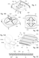
- the mass of fibers 31 is obtained by using two sheets 33A, 33B of capillary fibers 32.
- Each sheet 33A, 33B consist of a plurality of capillary fibers 32 disposed parallel to each other in a first direction X, and connected to each other by means of at least two threads 34A, 34B intertwined on the external surface of the capillary fibers 32 and oriented in a second direction Y inclined with respect to the first direction X, preferably perpendicular to the first direction X ( figs. 5B and 5C ).
- the second direction Y is also perpendicular to the longitudinal axis A.
- the threads 34A, 34B are useful for also keeping the capillary fibers 32 equidistant from each other.
- each sheet 33A, 33B the capillary fibers 32 preferentially form a single layer.
- the capillary fibers 32 can have a diameter of the order of a few hundred microns, for example 380 ⁇ m, and the threads 34A, 34B can have a thickness of the order of 10 ⁇ m.
- Each sheet 33A, 33B preferably comprises a plurality of threads 34A, 34B which are regularly distributed along the length of the capillary fibers 32 according to a predefined pitch P1.
- the pitch P1 can be of the order of a few millimeters, for example 10mm.
- the two sheets 33A, 33B are placed in reciprocal contact along a respective surface defined by the capillary fibers 32 ( fig. 5B ); pratically, the capillary fibers 32 are never in contact with each other because the contact occurs between the threads 34A, 34B of one sheet 33A, 33B, which protrude by their thickness on the external surface of the capillaries, and the capillary fibers 32 of the other sheet 33A, 33B. In this way, they form a sheet with a double layer of capillary fibers 32.
- the sheets 33A, 33B are disposed so that the threads 34A of a first sheet 33A are offset in the first direction X with respect to the threads 34B of the second sheet 33B. Obviously, the offset is preferably not equal to the pitch P between the threads 34A, 34B of a same sheet.
- the capillary fibers 32 are regularly distanced from each other, creating a homogeneous and repeatable three-dimensional matrix which defines a hydraulic section useful for the passage of the organic fluid such as to prevent the capillary fibers 32 from touching each other. Furthermore, a contact surface for the organic fluid is freed which, the number of capillary fibers 32 being equal, is higher and therefore allows to reduce the useful contact surface between the fibers and the organic fluid. In the case of blood, this is an advantage since it reduces the risk of allergic reactions of the blood with the material of the fibers.
- One way of achieving the offset of the threads 34A, 34B is simply to offset the two sheets 33A, 33B in the first direction X. It can for example be provided to resort to two reels 330A, 330B of sheets 33A, 33B of capillary fibers 32, and dispose them reciprocally offset in the first direction X in such a way as to be able to supply the sheets already offset with respect to each other ( fig. 5A ).
- the offset between the threads 34A, 34B of the two sheets 33A, 33B is advantageously smaller than the pitch P1 between the threads 34A, 34B of a same sheet 33A, 33B, so that the threads are separated from each other by a distance smaller than the pitch P1.
- the threads 34A, 34B are offset by a half pitch P1, in such a way as to be regularly distanced from each other by a distance equal to half the pitch P. In the case of a pitch P1 equal to 10mm, the threads 34A, 34B are distanced by 5mm in the sheet with a double layer ( fig. 5C ).
- the sheets 33A, 33B are offset with respect to each other also in the second direction Y.
- the capillary fibers 32 are suitably separated, in the second direction Y, by a second pitch P2. It is particularly advantageous to provide that the sheets 33A, 33B are offset by half of the second pitch P2, so that the capillary fibers 32 of a first sheet 33A are located between two capillary fibers 32 of the second sheet 33B ( fig. 5C ). In this way, the capillary fibers 32 form a more compact and more stable three-dimensional net.
- the mass 31 of capillary fibers 32 consists of two sheets 33A, 33B disposed as described above and folded in bellows fashion so as to fill the oxygenation chamber 30.
- Fig. 6 shows an alternative embodiment, in which the capillary fibers 32 are conformed in sub-groups 310.
- Each sub-group 310 comprises a support element 311 around which two sheets 33A, 33B of capillary fibers 32, disposed as described above, are wound on several loops ( fig. 7 ).
- the support element 311 has a substantially annular shape, with an internal aperture with a shape and sizes larger than those of the dome 40A, so as to not interfere with the useful hydraulic section of the oxygenator 10.
- the mass 31 of capillary fibers 32 is prepared, by supplying two sheets 33A, 33B placed in reciprocal contact in correspondence with a surface thereof and disposed in such a way that the threads 34A of the first sheet 33A are offset with respect to the threads 34B of the second sheet 33B ( fig. 5B ). It can for example be provided that the two sheets 33A, 33B are supplied offset with respect to each other in the first direction X, by a distance preferably smaller than the pitch P between the threads 34A, 34B of a same sheet 33A, 33B.
- the two sheets 33A, 33B are fed by respective reels 330A, 330B, which can be disposed offset, in such a way that the sheets 33A, 33B are already offset when they are supplied.
- each capillary fiber 32 of one sheet 33A is positioned resting on the respective threads between two capillary fibers 32 of the other sheet 33B ( fig. 5C ).
- the capillary fibers 32 of the two sheets 33A, 33B are therefore indicatively distanced from each other by 10 ⁇ m.
- the two sheets 33A, 33B taken together are then shaped in order to enter the oxygenation chamber 30 in order to fill it.
- the sheets 33A, 33B are folded in bellows fashion, in order to obtain different double layers of capillary fibers 32 accumulated on each other.
- the mass 31 thus obtained is then inserted into the oxygenation chamber 30.
- the thickness can be any thickness whatsoever, according to the requirements or sizes of the oxygenation chamber 30 to be filled, or also the number of sub-groups 310 to be used.
- the sub-groups 310 are then disposed stacked in the oxygenation chamber 30, as shown in fig. 6 .
- the container body 20 is hermetically closed.
- the oxygenator is subsequently connected, by means of the connection ducts 21A, 22A, 23A, 24A and possibly also by means of the upper aperture 43, if provided, to a suitable circuit, for example an extracorporeal circuit for blood circulation, or the circulation of another organic fluid.
- a suitable circuit for example an extracorporeal circuit for blood circulation, or the circulation of another organic fluid.
- the functioning of the oxygenator 10 is similar to that of known oxygenators 10.
Landscapes
- Health & Medical Sciences (AREA)
- Urology & Nephrology (AREA)
- Heart & Thoracic Surgery (AREA)
- Emergency Medicine (AREA)
- Engineering & Computer Science (AREA)
- Chemical & Material Sciences (AREA)
- Chemical Kinetics & Catalysis (AREA)
- Public Health (AREA)
- Hematology (AREA)
- Life Sciences & Earth Sciences (AREA)
- Animal Behavior & Ethology (AREA)
- General Health & Medical Sciences (AREA)
- Anesthesiology (AREA)
- Veterinary Medicine (AREA)
- Vascular Medicine (AREA)
- Biomedical Technology (AREA)
- Manufacturing & Machinery (AREA)
- External Artificial Organs (AREA)
- Medicines Containing Material From Animals Or Micro-Organisms (AREA)
- Physical Or Chemical Processes And Apparatus (AREA)
Priority Applications (4)
| Application Number | Priority Date | Filing Date | Title |
|---|---|---|---|
| RS20241182A RS66160B1 (sr) | 2020-10-29 | 2021-10-28 | Oksigenator organskih tečnosti |
| SM20240453T SMT202400453T1 (it) | 2020-10-29 | 2021-10-28 | Ossigenatore di fluidi organici |
| HRP20241464TT HRP20241464T1 (hr) | 2020-10-29 | 2021-10-28 | Oksigenator organskih tekućina |
| SI202130220T SI4237033T1 (sl) | 2020-10-29 | 2021-10-28 | Oksigenator organskih fluidov |
Applications Claiming Priority (2)
| Application Number | Priority Date | Filing Date | Title |
|---|---|---|---|
| IT102020000025762A IT202000025762A1 (it) | 2020-10-29 | 2020-10-29 | Ossigenatore di fluidi organici |
| PCT/IT2021/050357 WO2022091163A1 (en) | 2020-10-29 | 2021-10-28 | Oxygenator of organic fluids |
Publications (2)
| Publication Number | Publication Date |
|---|---|
| EP4237033A1 EP4237033A1 (en) | 2023-09-06 |
| EP4237033B1 true EP4237033B1 (en) | 2024-08-07 |
Family
ID=74194858
Family Applications (1)
| Application Number | Title | Priority Date | Filing Date |
|---|---|---|---|
| EP21811527.7A Active EP4237033B1 (en) | 2020-10-29 | 2021-10-28 | Oxygenator of organic fluids |
Country Status (20)
| Country | Link |
|---|---|
| US (1) | US20240261480A1 (pl) |
| EP (1) | EP4237033B1 (pl) |
| JP (1) | JP2023547682A (pl) |
| KR (1) | KR20230097104A (pl) |
| AU (1) | AU2021371184A1 (pl) |
| CA (1) | CA3200416A1 (pl) |
| DK (1) | DK4237033T3 (pl) |
| ES (1) | ES2995611T3 (pl) |
| FI (1) | FI4237033T3 (pl) |
| HR (1) | HRP20241464T1 (pl) |
| HU (1) | HUE068897T2 (pl) |
| IT (1) | IT202000025762A1 (pl) |
| LT (1) | LT4237033T (pl) |
| PL (1) | PL4237033T3 (pl) |
| PT (1) | PT4237033T (pl) |
| RS (1) | RS66160B1 (pl) |
| SI (1) | SI4237033T1 (pl) |
| SM (1) | SMT202400453T1 (pl) |
| WO (1) | WO2022091163A1 (pl) |
| ZA (1) | ZA202305702B (pl) |
Families Citing this family (1)
| Publication number | Priority date | Publication date | Assignee | Title |
|---|---|---|---|---|
| EP4706704A2 (en) | 2016-09-22 | 2026-03-11 | Michigan Critical Care Consultants, Inc. | Devices and methods for extracorporeal conditioning of blood |
Family Cites Families (6)
| Publication number | Priority date | Publication date | Assignee | Title |
|---|---|---|---|---|
| US5429184A (en) * | 1994-03-28 | 1995-07-04 | Minntech Corporation | Wound heat exchanger oxygenator |
| US6113782A (en) * | 1998-07-28 | 2000-09-05 | Terumo Cardiovascular Systems Corporation | Potting of tubular bundles in housing |
| JP4301006B2 (ja) * | 2004-01-07 | 2009-07-22 | ニプロ株式会社 | 人工肺 |
| IT201700032687A1 (it) | 2017-03-24 | 2018-09-24 | Qura S R L | Un ossigenatore di fluidi organici |
| WO2020010286A1 (en) * | 2018-07-03 | 2020-01-09 | The General Hospital Corporation | System and method for extracorporeal carbon monoxide removal with phototherapy |
| GB201814021D0 (en) * | 2018-08-29 | 2018-10-10 | Qinetiq Ltd | Product and process |
-
2020
- 2020-10-29 IT IT102020000025762A patent/IT202000025762A1/it unknown
-
2021
- 2021-10-28 SI SI202130220T patent/SI4237033T1/sl unknown
- 2021-10-28 PT PT218115277T patent/PT4237033T/pt unknown
- 2021-10-28 SM SM20240453T patent/SMT202400453T1/it unknown
- 2021-10-28 JP JP2023527286A patent/JP2023547682A/ja active Pending
- 2021-10-28 LT LTEPPCT/IT2021/050357T patent/LT4237033T/lt unknown
- 2021-10-28 RS RS20241182A patent/RS66160B1/sr unknown
- 2021-10-28 PL PL21811527.7T patent/PL4237033T3/pl unknown
- 2021-10-28 US US18/034,540 patent/US20240261480A1/en active Pending
- 2021-10-28 ES ES21811527T patent/ES2995611T3/es active Active
- 2021-10-28 FI FIEP21811527.7T patent/FI4237033T3/fi active
- 2021-10-28 CA CA3200416A patent/CA3200416A1/en active Pending
- 2021-10-28 HU HUE21811527A patent/HUE068897T2/hu unknown
- 2021-10-28 EP EP21811527.7A patent/EP4237033B1/en active Active
- 2021-10-28 DK DK21811527.7T patent/DK4237033T3/da active
- 2021-10-28 AU AU2021371184A patent/AU2021371184A1/en active Pending
- 2021-10-28 HR HRP20241464TT patent/HRP20241464T1/hr unknown
- 2021-10-28 KR KR1020237017822A patent/KR20230097104A/ko active Pending
- 2021-10-28 WO PCT/IT2021/050357 patent/WO2022091163A1/en not_active Ceased
-
2023
- 2023-05-26 ZA ZA2023/05702A patent/ZA202305702B/en unknown
Also Published As
| Publication number | Publication date |
|---|---|
| CN116685365A (zh) | 2023-09-01 |
| CA3200416A1 (en) | 2022-05-05 |
| US20240261480A1 (en) | 2024-08-08 |
| PL4237033T3 (pl) | 2025-01-20 |
| EP4237033A1 (en) | 2023-09-06 |
| SMT202400453T1 (it) | 2025-01-14 |
| WO2022091163A1 (en) | 2022-05-05 |
| IT202000025762A1 (it) | 2022-04-29 |
| SI4237033T1 (sl) | 2025-02-28 |
| PT4237033T (pt) | 2024-11-07 |
| KR20230097104A (ko) | 2023-06-30 |
| DK4237033T3 (da) | 2024-11-11 |
| ES2995611T3 (en) | 2025-02-10 |
| ZA202305702B (en) | 2024-02-28 |
| HUE068897T2 (hu) | 2025-02-28 |
| RS66160B1 (sr) | 2024-12-31 |
| HRP20241464T1 (hr) | 2025-01-03 |
| FI4237033T3 (fi) | 2024-11-04 |
| AU2021371184A1 (en) | 2023-06-22 |
| LT4237033T (lt) | 2024-11-25 |
| JP2023547682A (ja) | 2023-11-13 |
Similar Documents
| Publication | Publication Date | Title |
|---|---|---|
| US5817278A (en) | Blood oxygenator and method of oxygenating blood | |
| EP0345983B1 (en) | Fluid treatment apparatus | |
| US5264171A (en) | Method of making spiral-wound hollow fiber membrane fabric cartridges and modules having flow-directing baffles | |
| US5236665A (en) | Hollow fiber treatment apparatus and membrane oxygenator | |
| US5698161A (en) | Hollow, multi-dimensional array membrane | |
| IL41075A (en) | Mass transfer device having a wound tubular diffusion membrane | |
| EP4237033B1 (en) | Oxygenator of organic fluids | |
| US5263982A (en) | Hollow fiber membrane type artificial lung | |
| CN116685365B (zh) | 有机流体氧合器 | |
| EP0530232B1 (en) | Hollow fiber fluid treatment apparatus and blood oxygenator | |
| EP2585130B1 (en) | A device for treating blood in an extracorporeal circulation | |
| JPH02102660A (ja) | 中空糸型流体処理装置 | |
| JPH09150041A (ja) | 外部灌流型気液接触モジュール | |
| WO2023078927A1 (en) | Oxygenator | |
| JPS6311972Y2 (pl) | ||
| JPH05245348A (ja) | 一体式乱流プロモーターを有する渦巻き形中空繊維膜織物カートリッジ及びモジュール | |
| JPS60225572A (ja) | 中空糸膜型人工肺 | |
| JPH04504211A (ja) | 複数血管膜酸素供給器 | |
| JPH042066B2 (pl) | ||
| JPH03264074A (ja) | 中空糸膜型人工肺とその配糸方法 | |
| JPS6145771A (ja) | 中空糸膜型人工肺 | |
| JPH09234245A (ja) | 外部灌流型人工肺 | |
| JPS6137251A (ja) | 熱交換器内蔵型人工肺 | |
| ITBO960350A1 (it) | Apparecchiatura, e relativo procedimento di fabbricazione, per il trattamento termico e l'ossigenazione del sangue | |
| JPH06181747A (ja) | ホローファイバーカートリッジ |
Legal Events
| Date | Code | Title | Description |
|---|---|---|---|
| REG | Reference to a national code |
Ref country code: HR Ref legal event code: TUEP Ref document number: P20241464T Country of ref document: HR |
|
| STAA | Information on the status of an ep patent application or granted ep patent |
Free format text: STATUS: UNKNOWN |
|
| STAA | Information on the status of an ep patent application or granted ep patent |
Free format text: STATUS: THE INTERNATIONAL PUBLICATION HAS BEEN MADE |
|
| PUAI | Public reference made under article 153(3) epc to a published international application that has entered the european phase |
Free format text: ORIGINAL CODE: 0009012 |
|
| STAA | Information on the status of an ep patent application or granted ep patent |
Free format text: STATUS: REQUEST FOR EXAMINATION WAS MADE |
|
| 17P | Request for examination filed |
Effective date: 20230526 |
|
| AK | Designated contracting states |
Kind code of ref document: A1 Designated state(s): AL AT BE BG CH CY CZ DE DK EE ES FI FR GB GR HR HU IE IS IT LI LT LU LV MC MK MT NL NO PL PT RO RS SE SI SK SM TR |
|
| RAP3 | Party data changed (applicant data changed or rights of an application transferred) |
Owner name: SPECTRUM MEDICAL SRL |
|
| DAV | Request for validation of the european patent (deleted) | ||
| DAX | Request for extension of the european patent (deleted) | ||
| GRAP | Despatch of communication of intention to grant a patent |
Free format text: ORIGINAL CODE: EPIDOSNIGR1 |
|
| STAA | Information on the status of an ep patent application or granted ep patent |
Free format text: STATUS: GRANT OF PATENT IS INTENDED |
|
| INTG | Intention to grant announced |
Effective date: 20240301 |
|
| GRAS | Grant fee paid |
Free format text: ORIGINAL CODE: EPIDOSNIGR3 |
|
| GRAA | (expected) grant |
Free format text: ORIGINAL CODE: 0009210 |
|
| STAA | Information on the status of an ep patent application or granted ep patent |
Free format text: STATUS: THE PATENT HAS BEEN GRANTED |
|
| AK | Designated contracting states |
Kind code of ref document: B1 Designated state(s): AL AT BE BG CH CY CZ DE DK EE ES FI FR GB GR HR HU IE IS IT LI LT LU LV MC MK MT NL NO PL PT RO RS SE SI SK SM TR |
|
| REG | Reference to a national code |
Ref country code: GB Ref legal event code: FG4D |
|
| REG | Reference to a national code |
Ref country code: CH Ref legal event code: EP |
|
| REG | Reference to a national code |
Ref country code: DE Ref legal event code: R096 Ref document number: 602021017004 Country of ref document: DE |
|
| REG | Reference to a national code |
Ref country code: IE Ref legal event code: FG4D |
|
| REG | Reference to a national code |
Ref country code: FI Ref legal event code: FGE |
|
| REG | Reference to a national code |
Ref country code: NL Ref legal event code: FP |
|
| REG | Reference to a national code |
Ref country code: PT Ref legal event code: SC4A Ref document number: 4237033 Country of ref document: PT Date of ref document: 20241107 Kind code of ref document: T Free format text: AVAILABILITY OF NATIONAL TRANSLATION Effective date: 20241031 |
|
| REG | Reference to a national code |
Ref country code: DK Ref legal event code: T3 Effective date: 20241104 |
|
| REG | Reference to a national code |
Ref country code: SE Ref legal event code: TRGR |
|
| REG | Reference to a national code |
Ref country code: EE Ref legal event code: FG4A Ref document number: E024667 Country of ref document: EE Effective date: 20241106 |
|
| REG | Reference to a national code |
Ref country code: SK Ref legal event code: T3 Ref document number: E 45297 Country of ref document: SK |
|
| REG | Reference to a national code |
Ref country code: HR Ref legal event code: ODRP Ref document number: P20241464T Country of ref document: HR Payment date: 20241025 Year of fee payment: 4 |
|
| REG | Reference to a national code |
Ref country code: GR Ref legal event code: EP Ref document number: 20240402592 Country of ref document: GR Effective date: 20241209 |
|
| REG | Reference to a national code |
Ref country code: HR Ref legal event code: T1PR Ref document number: P20241464 Country of ref document: HR |
|
| PG25 | Lapsed in a contracting state [announced via postgrant information from national office to epo] |
Ref country code: IS Free format text: LAPSE BECAUSE OF FAILURE TO SUBMIT A TRANSLATION OF THE DESCRIPTION OR TO PAY THE FEE WITHIN THE PRESCRIBED TIME-LIMIT Effective date: 20241207 |
|
| PG25 | Lapsed in a contracting state [announced via postgrant information from national office to epo] |
Ref country code: IS Free format text: LAPSE BECAUSE OF FAILURE TO SUBMIT A TRANSLATION OF THE DESCRIPTION OR TO PAY THE FEE WITHIN THE PRESCRIBED TIME-LIMIT Effective date: 20241207 |
|
| REG | Reference to a national code |
Ref country code: ES Ref legal event code: FG2A Ref document number: 2995611 Country of ref document: ES Kind code of ref document: T3 Effective date: 20250210 |
|
| REG | Reference to a national code |
Ref country code: HU Ref legal event code: AG4A Ref document number: E068897 Country of ref document: HU |
|
| REG | Reference to a national code |
Ref country code: DE Ref legal event code: R097 Ref document number: 602021017004 Country of ref document: DE |
|
| PLBE | No opposition filed within time limit |
Free format text: ORIGINAL CODE: 0009261 |
|
| STAA | Information on the status of an ep patent application or granted ep patent |
Free format text: STATUS: NO OPPOSITION FILED WITHIN TIME LIMIT |
|
| 26N | No opposition filed |
Effective date: 20250508 |
|
| PGFP | Annual fee paid to national office [announced via postgrant information from national office to epo] |
Ref country code: SM Payment date: 20250813 Year of fee payment: 5 |
|
| PGFP | Annual fee paid to national office [announced via postgrant information from national office to epo] |
Ref country code: GR Payment date: 20250922 Year of fee payment: 5 |
|
| REG | Reference to a national code |
Ref country code: AT Ref legal event code: UEP Ref document number: 1710226 Country of ref document: AT Kind code of ref document: T Effective date: 20240807 |
|
| PGFP | Annual fee paid to national office [announced via postgrant information from national office to epo] |
Ref country code: MT Payment date: 20250812 Year of fee payment: 5 |
|
| PGFP | Annual fee paid to national office [announced via postgrant information from national office to epo] |
Ref country code: SK Payment date: 20250918 Year of fee payment: 5 |
|
| PGFP | Annual fee paid to national office [announced via postgrant information from national office to epo] |
Ref country code: SI Payment date: 20251008 Year of fee payment: 5 |
|
| REG | Reference to a national code |
Ref country code: CH Ref legal event code: U11 Free format text: ST27 STATUS EVENT CODE: U-0-0-U10-U11 (AS PROVIDED BY THE NATIONAL OFFICE) Effective date: 20251101 |
|
| PGFP | Annual fee paid to national office [announced via postgrant information from national office to epo] |
Ref country code: HU Payment date: 20251017 Year of fee payment: 5 |
|
| PGFP | Annual fee paid to national office [announced via postgrant information from national office to epo] |
Ref country code: LU Payment date: 20251027 Year of fee payment: 5 Ref country code: NL Payment date: 20251027 Year of fee payment: 5 |
|
| REG | Reference to a national code |
Ref country code: HR Ref legal event code: ODRP Ref document number: P20241464 Country of ref document: HR Payment date: 20251013 Year of fee payment: 5 |
|
| PGFP | Annual fee paid to national office [announced via postgrant information from national office to epo] |
Ref country code: PT Payment date: 20251007 Year of fee payment: 5 |
|
| PGFP | Annual fee paid to national office [announced via postgrant information from national office to epo] |
Ref country code: IS Payment date: 20251024 Year of fee payment: 5 Ref country code: DE Payment date: 20251028 Year of fee payment: 5 |
|
| PGFP | Annual fee paid to national office [announced via postgrant information from national office to epo] |
Ref country code: LT Payment date: 20251007 Year of fee payment: 5 Ref country code: GB Payment date: 20251021 Year of fee payment: 5 |
|
| PGFP | Annual fee paid to national office [announced via postgrant information from national office to epo] |
Ref country code: NO Payment date: 20251020 Year of fee payment: 5 Ref country code: MC Payment date: 20251020 Year of fee payment: 5 |
|
| PGFP | Annual fee paid to national office [announced via postgrant information from national office to epo] |
Ref country code: MK Payment date: 20251007 Year of fee payment: 5 Ref country code: AT Payment date: 20260113 Year of fee payment: 5 |
|
| PGFP | Annual fee paid to national office [announced via postgrant information from national office to epo] |
Ref country code: FI Payment date: 20251027 Year of fee payment: 5 Ref country code: DK Payment date: 20251024 Year of fee payment: 5 |
|
| PG25 | Lapsed in a contracting state [announced via postgrant information from national office to epo] |
Ref country code: IT Free format text: LAPSE BECAUSE OF NON-PAYMENT OF DUE FEES Effective date: 20241028 |
|
| PGFP | Annual fee paid to national office [announced via postgrant information from national office to epo] |
Ref country code: HR Payment date: 20251013 Year of fee payment: 5 Ref country code: FR Payment date: 20251027 Year of fee payment: 5 |
|
| PGFP | Annual fee paid to national office [announced via postgrant information from national office to epo] |
Ref country code: AL Payment date: 20251029 Year of fee payment: 5 Ref country code: TR Payment date: 20251007 Year of fee payment: 5 Ref country code: BE Payment date: 20251027 Year of fee payment: 5 |
|
| PGFP | Annual fee paid to national office [announced via postgrant information from national office to epo] |
Ref country code: SE Payment date: 20251024 Year of fee payment: 5 Ref country code: CH Payment date: 20251101 Year of fee payment: 5 |
|
| PGFP | Annual fee paid to national office [announced via postgrant information from national office to epo] |
Ref country code: IE Payment date: 20251020 Year of fee payment: 5 Ref country code: CZ Payment date: 20251009 Year of fee payment: 5 Ref country code: CY Payment date: 20251016 Year of fee payment: 5 |
|
| PGFP | Annual fee paid to national office [announced via postgrant information from national office to epo] |
Ref country code: LV Payment date: 20251023 Year of fee payment: 5 |
|
| PGFP | Annual fee paid to national office [announced via postgrant information from national office to epo] |
Ref country code: PL Payment date: 20251006 Year of fee payment: 5 Ref country code: BG Payment date: 20251028 Year of fee payment: 5 |
|
| PGFP | Annual fee paid to national office [announced via postgrant information from national office to epo] |
Ref country code: EE Payment date: 20251027 Year of fee payment: 5 |
|
| PGFP | Annual fee paid to national office [announced via postgrant information from national office to epo] |
Ref country code: RO Payment date: 20251013 Year of fee payment: 5 |
|
| PGFP | Annual fee paid to national office [announced via postgrant information from national office to epo] |
Ref country code: RS Payment date: 20251007 Year of fee payment: 5 |
|
| PGFP | Annual fee paid to national office [announced via postgrant information from national office to epo] |
Ref country code: ES Payment date: 20251118 Year of fee payment: 5 |
|
| PG25 | Lapsed in a contracting state [announced via postgrant information from national office to epo] |
Ref country code: IT Free format text: LAPSE BECAUSE OF NON-PAYMENT OF DUE FEES Effective date: 20241028 |
|
| PGFP | Annual fee paid to national office [announced via postgrant information from national office to epo] |
Ref country code: IT Payment date: 20250805 Year of fee payment: 5 |
|
| PGRI | Patent reinstated in contracting state [announced from national office to epo] |
Ref country code: IT Effective date: 20241031 |