EP4236726B1 - Regalsystem mit einem marmorregal - Google Patents
Regalsystem mit einem marmorregal Download PDFInfo
- Publication number
- EP4236726B1 EP4236726B1 EP21815661.0A EP21815661A EP4236726B1 EP 4236726 B1 EP4236726 B1 EP 4236726B1 EP 21815661 A EP21815661 A EP 21815661A EP 4236726 B1 EP4236726 B1 EP 4236726B1
- Authority
- EP
- European Patent Office
- Prior art keywords
- profile
- shelf
- marble
- support system
- wall
- Prior art date
- Legal status (The legal status is an assumption and is not a legal conclusion. Google has not performed a legal analysis and makes no representation as to the accuracy of the status listed.)
- Active
Links
Images


Classifications
-
- A—HUMAN NECESSITIES
- A47—FURNITURE; DOMESTIC ARTICLES OR APPLIANCES; COFFEE MILLS; SPICE MILLS; SUCTION CLEANERS IN GENERAL
- A47B—TABLES; DESKS; OFFICE FURNITURE; CABINETS; DRAWERS; GENERAL DETAILS OF FURNITURE
- A47B96/00—Details of cabinets, racks or shelf units not covered by a single one of groups A47B43/00 - A47B95/00; General details of furniture
- A47B96/06—Brackets or similar supporting means for cabinets, racks or shelves
- A47B96/066—Supporting means received within an edge of the shelf
-
- A—HUMAN NECESSITIES
- A47—FURNITURE; DOMESTIC ARTICLES OR APPLIANCES; COFFEE MILLS; SPICE MILLS; SUCTION CLEANERS IN GENERAL
- A47B—TABLES; DESKS; OFFICE FURNITURE; CABINETS; DRAWERS; GENERAL DETAILS OF FURNITURE
- A47B96/00—Details of cabinets, racks or shelf units not covered by a single one of groups A47B43/00 - A47B95/00; General details of furniture
- A47B96/02—Shelves
- A47B96/024—Shelves characterised by support bracket location means, e.g. fixing means between support bracket and shelf
-
- A—HUMAN NECESSITIES
- A47—FURNITURE; DOMESTIC ARTICLES OR APPLIANCES; COFFEE MILLS; SPICE MILLS; SUCTION CLEANERS IN GENERAL
- A47B—TABLES; DESKS; OFFICE FURNITURE; CABINETS; DRAWERS; GENERAL DETAILS OF FURNITURE
- A47B96/00—Details of cabinets, racks or shelf units not covered by a single one of groups A47B43/00 - A47B95/00; General details of furniture
- A47B96/02—Shelves
- A47B96/021—Structural features of shelf bases
-
- A—HUMAN NECESSITIES
- A47—FURNITURE; DOMESTIC ARTICLES OR APPLIANCES; COFFEE MILLS; SPICE MILLS; SUCTION CLEANERS IN GENERAL
- A47B—TABLES; DESKS; OFFICE FURNITURE; CABINETS; DRAWERS; GENERAL DETAILS OF FURNITURE
- A47B96/00—Details of cabinets, racks or shelf units not covered by a single one of groups A47B43/00 - A47B95/00; General details of furniture
- A47B96/06—Brackets or similar supporting means for cabinets, racks or shelves
-
- F—MECHANICAL ENGINEERING; LIGHTING; HEATING; WEAPONS; BLASTING
- F16—ENGINEERING ELEMENTS AND UNITS; GENERAL MEASURES FOR PRODUCING AND MAINTAINING EFFECTIVE FUNCTIONING OF MACHINES OR INSTALLATIONS; THERMAL INSULATION IN GENERAL
- F16M—FRAMES, CASINGS OR BEDS OF ENGINES, MACHINES OR APPARATUS, NOT SPECIFIC TO ENGINES, MACHINES OR APPARATUS PROVIDED FOR ELSEWHERE; STANDS; SUPPORTS
- F16M13/00—Other supports for positioning apparatus or articles; Means for steadying hand-held apparatus or articles
- F16M13/02—Other supports for positioning apparatus or articles; Means for steadying hand-held apparatus or articles for supporting on, or attaching to, an object, e.g. tree, gate, window-frame, cycle
- F16M13/025—Corner supports
Definitions
- the present invention refers, in general, to a shelf system with a marble shelf. More particularly, it relates to a shelf system comprising a marble shelf and an associated support system.
- the purpose and function of the present invention is to provide a shelf system with a marble shelf, which overcomes the problems of the known technique.
- a further scope of the invention is to provide a corbel system which enables a marble corbel to be fixed to a wall in a simple and fast manner.
- a further scope of the present invention is to provide a corbel system that allows a marble corbel to be attached to a wall without the need for heavy work on the wall, thus avoiding the intervention of skilled personnel.
- a further scope of the invention is to provide a shelf system that allows a marble shelf to be fixed to a wall without the use of visible supports, guaranteeing a high aesthetic effect.
- a shelf system comprising a marble shelf and a support system for fixing the marble shelf with at least one of its faces in contact with at least one wall.
- the support system comprises a profile with at least one fixing means in the form of projections for fixing the profile to the wall, the groove being of a shape homologous to the profile, so that, once the profile is fixed to the wall, the shelf is coupled to the profile by means of an adhesive.
- the assembly of a marble shelf to a wall is practical and fast, as it is sufficient to make one or more holes in a wall, through which one or more profiles are fixed to which, in turn, the marble shelf will be fixed.
- the support system comprises a metal sheet including the profile and at least two protrusions.
- the support system is made in one piece, so that unwanted edges or steps are avoided.
- the profile can be rectangular, so that it fits comfortably into the groove in the marble shelf.
- the profile and the two or more protrusions can all be arranged on the same plane, so that the entire support system consists of just the metal sheet with a well-defined perimeter profile.
- the two or more projections may be arranged in line with, or slightly within, the two ends of the rectangular profile.
- the perimeter profile of the support system i.e. the metal sheet can be made by one or more of the following processes: blanking, stamping, laser cutting, water cutting.
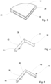
- a shelf system comprising a marble shelf 12 and a first support system 14, a system suitable for being fixed to the corner formed by a first wall P1 and a second wall P2 which are orthogonal to each other.
- the marble shelf 12 has a quarter-circle shape and, as shown in figure 3 , a groove 16 is cut into it.
- the support system 14 comprises a corner profile 18, i.e. "L" shaped, formed by a first portion 20 and a second portion 22 orthogonal to each other and having a rectangular cross section.
- the groove 16 has a form homologous to the corner profile 18 and therefore develops on the two faces 26, 28 of the marble shelf 12 which are in contact with the walls P1 and P2.
- the groove 16 only develops on the two faces 26, 28, without affecting the visible outer edge 30 of the marble shelf 12.
- first of all four holes F are drilled in the walls P1 and P2 (for ease of reading only one hole is indicated in figure 2 ), precisely two in the first wall P1 and two in the second wall P2, in the same position and corresponding to the holes 24 drilled in the corner profile 18.
- the next step is to fasten the support system 14 to the walls. This involves fastening the angle profile 18 to the walls P1 and P2 using pressure screws or other equivalent fastening methods, if necessary by inserting suitable plugs in the holes F in the walls P1 and P2.
- the marble shelf 12 is coupled to the corner profile 18 using adhesive substances such as silicone.
- the shelf system 10 according to the invention thus fixed to the walls P1 and P2, presents only the marble shelf 12 in view, while the corresponding support system 14 is hidden between the same marble shelf 12 and the walls P1 and P2.
- the aesthetics of the shelf system 10 is optimal and the fixing of the support system 14 to the walls P1 and P2 is simple and does not require the intervention of specialised personnel.
- a shelf system analogous to the previously illustrated shelf system 10 may comprise a marble shelf and a second support system 32, illustrated in figure 4 .
- the second support system 32 comprises a corner profile 34, formed by a first portion 36 and a second portion 38 orthogonal to each other and having a triangular-shaped cross-section.
- corner profile 34 In the corner profile 34, four holes 40 are obtained, of which, for ease of reading, only one is indicated in figure 4 . Precisely, two holes are obtained in the first portion 36 of the corner profile 34 and two holes in the second portion 38 of the corner profile 34.
- the marble shelf to be coupled to the second support system 32 has a groove of a shape homologous to the corner profile 34.
- a shelf system analogous to the previously illustrated shelf system 10 may comprise a marble shelf and a second support system 42, illustrated in figure 5 .
- the second support system 42 comprises a corner profile 44, formed by a first portion 46 and a second portion 48 orthogonal to each other and having an inverted "L" shaped cross-section.
- the marble shelf to be coupled to the second support system 42 has a groove of homologous shape to the corner profile 44.
- a shelf system 60 comprises a marble shelf 62 and a third support system 64, and is suitable for attachment to a third wall P3.
- the marble shelf 62 has a parallelepiped shape, includes a face 66 suitable to go against the third wall P3 and in which a groove 68 is obtained.
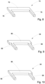
- the third support system 64 comprises a linear profile 70 to which two pins 72 are fixed.
- the bracket system 60 envisages firstly the creation of two holes F in the wall P3 arranged at a distance equal to that between the two pins 72.
- the dowels 72 are inserted in the same holes F and the linear profile 70 is fixed to the wall P3.
- the marble shelf 62 is coupled to the linear profile 70 using adhesives such as silicone.
- the shelf system 60 does not have any visible support systems, with consequent advantages from an aesthetic point of view.
- the shelf system 60 comprises the marble shelf 62 and, alternatively to the third support system 64, has a fourth support system 74 or a fifth support system 84 or a sixth support system 94.
- the fourth support system 74 made in a single body by shearing or stamping a metal sheet, comprises a rectangular profile 76 from which two protrusions 78 project, as visible in figure 8 .
- the two protrusions 78 are arranged at the ends of the rectangular profile 76.
- the fifth support system 84 made in a single body by shearing, stamping, laser cutting or water cutting a metal sheet, comprises a rectangular profile 86 from which two protrusions 88 protrude, as visible in figure 9 .
- the two protrusions 88 are arranged slightly inside the ends of the rectangular profile 86.
- the sixth support system 94 made in a single body by shearing, stamping, laser cutting or water cutting a metal sheet, comprises a rectangular profile 96 from which two protrusions 98 protrude, as visible in figure 10 .
- one of the two protrusions 98 is disposed slightly inside one of the two ends of the rectangular profile 96, while the other is in line with the other end of the rectangular profile 96.
- the fourth support system 74 or the fifth support system 84 or the sixth support system 94 may also be used to fix a marble shelf in the shape of a quarter moon, to two walls at right angles to each other.
- the two grooves are not continuous like the groove 16 illustrated for the shelf system 10 of figures 1, 2 , 3 .
- the shape of the elements used as the support system may vary, depending also on the application purposes of the bracket system itself.
Landscapes
- Engineering & Computer Science (AREA)
- General Engineering & Computer Science (AREA)
- Mechanical Engineering (AREA)
- Assembled Shelves (AREA)
- Warehouses Or Storage Devices (AREA)
Claims (7)
- Konsolensystem (60), das eine Marmorkonsole (62) und ein Trägersystem (74; 84; 94) umfasst, das geeignet ist, die Marmorkonsole (62) mit mindestens einer ihrer Flächen an der mindestens einen Wand zu befestigen, wobei in der mindestens einen Fläche der Marmorkonsole (62), die in die Wand eindringt, mindestens eine Nut erhalten wird und wobei das Trägersystem (74; 84; 94) ein Profil (76; 86; 96) mit mindestens einem Befestigungsmittel in Form von Vorsprüngen (78; 88; 98) aufweist, die geeignet sind, das Profil an der Wand zu befestigen, wobei die Nut eine zum Profil homologe Form aufweist, so dass, sobald das Profil an der Wand befestigt ist, das Regal mittels eines Klebstoffs mit dem Profil verbunden ist, wobei das Trägersystem (74; 84; 94) ein Metallblech aufweist, das das Profil (76; 86; 96) und mindestens zwei Vorsprünge (78; 88; 98) umfasst; dadurch gekennzeichnet, dass das Trägersystem (74; 84; 94) als ein einziger Körper ausgeführt ist.
- Trägersystem (60) nach dem vorhergehenden Anspruch, wobei das Profil (76; 86; 96) rechteckig ist.
- Konsolensystem (60) nach einem der vorhergehenden Ansprüche, wobei das Profil (76; 86; 96) und die mindestens zwei Vorsprünge (78; 88; 98) alle in der gleichen Ebene angeordnet sind.
- Konsolensystem (60) nach einem der vorangehenden Ansprüche, wobei zwei Vorsprünge (78) an den jeweiligen Enden des rechteckigen Profils (76) angeordnet sind.
- Konsolensystem (60) nach einem der Ansprüche 1 bis 3, wobei zwei Vorsprünge (88) etwas innerhalb der jeweiligen Enden des Rechteckprofils (76) angeordnet sind.
- Klammersystem (60) nach einem der Ansprüche 1 bis 3, wobei ein Vorsprung (98) leicht innerhalb eines der Enden des rechteckigen Profils (96) angeordnet ist, während ein anderer Vorsprung (98) mit dem gegenüberliegenden Ende des rechteckigen Profils (96) fluchtet.
- Klammersystem (60) nach einem der vorhergehenden Ansprüche, wobei das Metallblech eine Umfangskante aufweist, die das Profil (78; 88; 98) und die mindestens zwei Vorsprünge (78; 88; 98) definiert, wobei die Umfangskante durch eines oder mehrere der folgenden Verfahren erhalten wird: Stanzen, Prägen, Laserschneiden, Wasserschneiden.
Applications Claiming Priority (2)
| Application Number | Priority Date | Filing Date | Title |
|---|---|---|---|
| IT202000026095 | 2020-11-02 | ||
| PCT/IB2021/060123 WO2022091066A1 (en) | 2020-11-02 | 2021-11-02 | Shelf system comprising a marble shelf |
Publications (3)
| Publication Number | Publication Date |
|---|---|
| EP4236726A1 EP4236726A1 (de) | 2023-09-06 |
| EP4236726C0 EP4236726C0 (de) | 2025-01-08 |
| EP4236726B1 true EP4236726B1 (de) | 2025-01-08 |
Family
ID=74194910
Family Applications (1)
| Application Number | Title | Priority Date | Filing Date |
|---|---|---|---|
| EP21815661.0A Active EP4236726B1 (de) | 2020-11-02 | 2021-11-02 | Regalsystem mit einem marmorregal |
Country Status (5)
| Country | Link |
|---|---|
| US (1) | US20240008644A1 (de) |
| EP (1) | EP4236726B1 (de) |
| JP (1) | JP2024500278A (de) |
| CA (1) | CA3197247A1 (de) |
| WO (1) | WO2022091066A1 (de) |
Families Citing this family (2)
| Publication number | Priority date | Publication date | Assignee | Title |
|---|---|---|---|---|
| CA197113S (en) * | 2020-01-28 | 2022-01-31 | Schluter Systems Canada Inc | Shelf |
| CA197112S (en) * | 2020-01-28 | 2021-12-06 | Schluter Systems Canada Inc | Shelf |
Family Cites Families (26)
| Publication number | Priority date | Publication date | Assignee | Title |
|---|---|---|---|---|
| US3752088A (en) * | 1968-04-11 | 1973-08-14 | B Kapnek | Shelf assembly |
| US3718101A (en) * | 1971-05-18 | 1973-02-27 | F Sacks | Shelf |
| US4708310A (en) * | 1987-03-05 | 1987-11-24 | Tri-State Enterprises | Corner mounted tray |
| JP2528423Y2 (ja) * | 1991-04-23 | 1997-03-12 | タカラスタンダード株式会社 | コーナー棚 |
| CA2328650A1 (en) * | 2000-12-15 | 2002-06-15 | Jacob C. Santiago | Concealed cantilever shelf support |
| US8082859B2 (en) * | 2005-12-02 | 2011-12-27 | Lloyd Sevack | Blind shelf support and method of installation |
| JP4893492B2 (ja) * | 2007-06-19 | 2012-03-07 | パナソニック電工株式会社 | 棚装置 |
| US8225435B2 (en) * | 2008-01-22 | 2012-07-24 | Noble Company | Shower bench |
| US8985349B2 (en) * | 2013-01-16 | 2015-03-24 | Mw Products Llc | Corner shelf system for storing and displaying consumer electronic source components |
| US9402476B2 (en) * | 2014-10-06 | 2016-08-02 | Brian Crandall | Shower shelf |
| KR101733212B1 (ko) * | 2015-08-19 | 2017-05-08 | 김완태 | 벽체에 리벳팅한 브라켓과 이를 구비한 선반 |
| US11412850B2 (en) * | 2017-08-16 | 2022-08-16 | Salvatore Sisto | Floating shelf apparatus |
| US10602843B2 (en) * | 2017-08-16 | 2020-03-31 | Salvatore Sisto | Floating shelf apparatus |
| US9861198B2 (en) * | 2016-03-30 | 2018-01-09 | Kevin Anderson | Bracket to support a shelf |
| US10588412B2 (en) * | 2017-12-06 | 2020-03-17 | Shelf.Maid Llc | Floating shelf bracket with height adjustment system |
| US11432648B1 (en) * | 2018-07-29 | 2022-09-06 | Stronghold Brackets | Wall bracket |
| US10575641B1 (en) * | 2018-08-20 | 2020-03-03 | Rehau Industries, L.L.C. | Shelving system, shelf unit, and method of assembling shelf unit |
| CN111150247A (zh) * | 2018-11-08 | 2020-05-15 | 路易斯海曼有限公司 | 浮动搁板托架和使用浮动搁板托架的方法 |
| IT201900016343A1 (it) * | 2019-09-16 | 2021-03-16 | Leonardo Srl | Dispositivo di supporto perfezionato per ripiani di mobili |
| WO2022177879A1 (en) * | 2021-02-17 | 2022-08-25 | Salto, Llc | Wall-mountable accessory |
| US11596230B2 (en) * | 2021-06-09 | 2023-03-07 | Andrew Horezga | Universal shelf bracket |
| US20220400861A1 (en) * | 2021-06-22 | 2022-12-22 | Eye Designs, Llc | Floating shelf system |
| US12137805B2 (en) * | 2021-10-22 | 2024-11-12 | Silicate Studio Home, LLC | Floating shelf bracket with threaded rods |
| US12011088B2 (en) * | 2021-10-22 | 2024-06-18 | Silicate Studio Home LLC | Floating shelf bracket with welded rods |
| US11825947B1 (en) * | 2022-05-23 | 2023-11-28 | Silicate Studio Home, LLC | Floating shelf system |
| US11825946B1 (en) * | 2022-05-25 | 2023-11-28 | Silicate Studio Home, LLC | Modular floating shelf system |
-
2021
- 2021-11-02 US US18/251,525 patent/US20240008644A1/en not_active Abandoned
- 2021-11-02 EP EP21815661.0A patent/EP4236726B1/de active Active
- 2021-11-02 CA CA3197247A patent/CA3197247A1/en active Pending
- 2021-11-02 WO PCT/IB2021/060123 patent/WO2022091066A1/en not_active Ceased
- 2021-11-02 JP JP2023528012A patent/JP2024500278A/ja active Pending
Also Published As
| Publication number | Publication date |
|---|---|
| CA3197247A1 (en) | 2022-05-05 |
| EP4236726A1 (de) | 2023-09-06 |
| EP4236726C0 (de) | 2025-01-08 |
| WO2022091066A1 (en) | 2022-05-05 |
| JP2024500278A (ja) | 2024-01-09 |
| US20240008644A1 (en) | 2024-01-11 |
Similar Documents
| Publication | Publication Date | Title |
|---|---|---|
| EP3411599B1 (de) | Set aus platten für eine montiertes produkt | |
| EP4236726B1 (de) | Regalsystem mit einem marmorregal | |
| US6223917B1 (en) | Profile arrangement for building exhibition or shop systems | |
| EP4076090A1 (de) | Satz aus platten mit mechanischer verriegelungsvorrichtung | |
| US11371247B2 (en) | Panels, mounting clamps and wall or ceiling covering for a 3-dimensional pattern of wall- and ceiling panels | |
| US9133625B2 (en) | Sheathing element for covering preexisting physical structures | |
| EP3464758B1 (de) | Plattensysteme und -komponenten | |
| EP0437903B1 (de) | Anpassbares, vertikales oder horizontales Wandsystem | |
| US4617772A (en) | Wall panel joiner | |
| US20140341647A1 (en) | Profiled frame element | |
| US4917528A (en) | Panel joint | |
| US4470235A (en) | Pillar for supports and wall elements | |
| KR200200938Y1 (ko) | 콘크리트 시공용 패널 | |
| US20210317667A1 (en) | Façade system | |
| KR101942056B1 (ko) | 조립식 가구 | |
| US4065901A (en) | Connecting element for wall or ceiling panels when constructed by a dry method | |
| WO2002034085A1 (en) | Panel edging system | |
| KR20060065232A (ko) | 캐비넷용 코너연결 구조물 | |
| JP4477940B2 (ja) | 組み立て式棚の支柱 | |
| WO2008012574A1 (en) | Improvements in and relating to fixing apparatus | |
| WO2025088008A1 (en) | System for the construction of a sound insulation element, connecting elements for connecting of profile-elements of a sound insulation element and connector for connecting a support profile to at least one profile element of a sound insulation element | |
| KR200243008Y1 (ko) | 천정설치용 판재 구조 | |
| CA1301235C (en) | Corner construction apparatus and method | |
| EP4222326A1 (de) | Verbindungssystem für den aufbau einer trennwand | |
| GB2593654A (en) | Façade system |
Legal Events
| Date | Code | Title | Description |
|---|---|---|---|
| STAA | Information on the status of an ep patent application or granted ep patent |
Free format text: STATUS: UNKNOWN |
|
| STAA | Information on the status of an ep patent application or granted ep patent |
Free format text: STATUS: THE INTERNATIONAL PUBLICATION HAS BEEN MADE |
|
| PUAI | Public reference made under article 153(3) epc to a published international application that has entered the european phase |
Free format text: ORIGINAL CODE: 0009012 |
|
| STAA | Information on the status of an ep patent application or granted ep patent |
Free format text: STATUS: REQUEST FOR EXAMINATION WAS MADE |
|
| 17P | Request for examination filed |
Effective date: 20230531 |
|
| AK | Designated contracting states |
Kind code of ref document: A1 Designated state(s): AL AT BE BG CH CY CZ DE DK EE ES FI FR GB GR HR HU IE IS IT LI LT LU LV MC MK MT NL NO PL PT RO RS SE SI SK SM TR |
|
| DAV | Request for validation of the european patent (deleted) | ||
| DAX | Request for extension of the european patent (deleted) | ||
| GRAP | Despatch of communication of intention to grant a patent |
Free format text: ORIGINAL CODE: EPIDOSNIGR1 |
|
| STAA | Information on the status of an ep patent application or granted ep patent |
Free format text: STATUS: GRANT OF PATENT IS INTENDED |
|
| INTG | Intention to grant announced |
Effective date: 20240826 |
|
| GRAS | Grant fee paid |
Free format text: ORIGINAL CODE: EPIDOSNIGR3 |
|
| GRAA | (expected) grant |
Free format text: ORIGINAL CODE: 0009210 |
|
| STAA | Information on the status of an ep patent application or granted ep patent |
Free format text: STATUS: THE PATENT HAS BEEN GRANTED |
|
| AK | Designated contracting states |
Kind code of ref document: B1 Designated state(s): AL AT BE BG CH CY CZ DE DK EE ES FI FR GB GR HR HU IE IS IT LI LT LU LV MC MK MT NL NO PL PT RO RS SE SI SK SM TR |
|
| REG | Reference to a national code |
Ref country code: GB Ref legal event code: FG4D |
|
| REG | Reference to a national code |
Ref country code: CH Ref legal event code: EP |
|
| REG | Reference to a national code |
Ref country code: DE Ref legal event code: R096 Ref document number: 602021024774 Country of ref document: DE |
|
| REG | Reference to a national code |
Ref country code: IE Ref legal event code: FG4D |
|
| U01 | Request for unitary effect filed |
Effective date: 20250205 |
|
| U07 | Unitary effect registered |
Designated state(s): AT BE BG DE DK EE FI FR IT LT LU LV MT NL PT RO SE SI Effective date: 20250220 |
|
| PG25 | Lapsed in a contracting state [announced via postgrant information from national office to epo] |
Ref country code: RS Free format text: LAPSE BECAUSE OF FAILURE TO SUBMIT A TRANSLATION OF THE DESCRIPTION OR TO PAY THE FEE WITHIN THE PRESCRIBED TIME-LIMIT Effective date: 20250408 |
|
| PG25 | Lapsed in a contracting state [announced via postgrant information from national office to epo] |
Ref country code: PL Free format text: LAPSE BECAUSE OF FAILURE TO SUBMIT A TRANSLATION OF THE DESCRIPTION OR TO PAY THE FEE WITHIN THE PRESCRIBED TIME-LIMIT Effective date: 20250108 |
|
| PG25 | Lapsed in a contracting state [announced via postgrant information from national office to epo] |
Ref country code: ES Free format text: LAPSE BECAUSE OF FAILURE TO SUBMIT A TRANSLATION OF THE DESCRIPTION OR TO PAY THE FEE WITHIN THE PRESCRIBED TIME-LIMIT Effective date: 20250108 |
|
| PG25 | Lapsed in a contracting state [announced via postgrant information from national office to epo] |
Ref country code: IS Free format text: LAPSE BECAUSE OF FAILURE TO SUBMIT A TRANSLATION OF THE DESCRIPTION OR TO PAY THE FEE WITHIN THE PRESCRIBED TIME-LIMIT Effective date: 20250508 Ref country code: NO Free format text: LAPSE BECAUSE OF FAILURE TO SUBMIT A TRANSLATION OF THE DESCRIPTION OR TO PAY THE FEE WITHIN THE PRESCRIBED TIME-LIMIT Effective date: 20250408 |
|
| PG25 | Lapsed in a contracting state [announced via postgrant information from national office to epo] |
Ref country code: HR Free format text: LAPSE BECAUSE OF FAILURE TO SUBMIT A TRANSLATION OF THE DESCRIPTION OR TO PAY THE FEE WITHIN THE PRESCRIBED TIME-LIMIT Effective date: 20250108 |
|
| PG25 | Lapsed in a contracting state [announced via postgrant information from national office to epo] |
Ref country code: GR Free format text: LAPSE BECAUSE OF FAILURE TO SUBMIT A TRANSLATION OF THE DESCRIPTION OR TO PAY THE FEE WITHIN THE PRESCRIBED TIME-LIMIT Effective date: 20250409 |
|
| PG25 | Lapsed in a contracting state [announced via postgrant information from national office to epo] |
Ref country code: SM Free format text: LAPSE BECAUSE OF FAILURE TO SUBMIT A TRANSLATION OF THE DESCRIPTION OR TO PAY THE FEE WITHIN THE PRESCRIBED TIME-LIMIT Effective date: 20250108 |
|
| PG25 | Lapsed in a contracting state [announced via postgrant information from national office to epo] |
Ref country code: CZ Free format text: LAPSE BECAUSE OF FAILURE TO SUBMIT A TRANSLATION OF THE DESCRIPTION OR TO PAY THE FEE WITHIN THE PRESCRIBED TIME-LIMIT Effective date: 20250108 |
|
| PG25 | Lapsed in a contracting state [announced via postgrant information from national office to epo] |
Ref country code: SK Free format text: LAPSE BECAUSE OF FAILURE TO SUBMIT A TRANSLATION OF THE DESCRIPTION OR TO PAY THE FEE WITHIN THE PRESCRIBED TIME-LIMIT Effective date: 20250108 |
|
| PLBE | No opposition filed within time limit |
Free format text: ORIGINAL CODE: 0009261 |
|
| STAA | Information on the status of an ep patent application or granted ep patent |
Free format text: STATUS: NO OPPOSITION FILED WITHIN TIME LIMIT |