EP3464758B1 - Plattensysteme und -komponenten - Google Patents
Plattensysteme und -komponenten Download PDFInfo
- Publication number
- EP3464758B1 EP3464758B1 EP17805420.1A EP17805420A EP3464758B1 EP 3464758 B1 EP3464758 B1 EP 3464758B1 EP 17805420 A EP17805420 A EP 17805420A EP 3464758 B1 EP3464758 B1 EP 3464758B1
- Authority
- EP
- European Patent Office
- Prior art keywords
- support
- fastener
- fastening element
- portions
- mating portion
- Prior art date
- Legal status (The legal status is an assumption and is not a legal conclusion. Google has not performed a legal analysis and makes no representation as to the accuracy of the status listed.)
- Active
Links
Images


Classifications
-
- E—FIXED CONSTRUCTIONS
- E04—BUILDING
- E04H—BUILDINGS OR LIKE STRUCTURES FOR PARTICULAR PURPOSES; SWIMMING OR SPLASH BATHS OR POOLS; MASTS; FENCING; TENTS OR CANOPIES, IN GENERAL
- E04H17/00—Fencing, e.g. fences, enclosures, corrals
- E04H17/14—Fences constructed of rigid elements, e.g. with additional wire fillings or with posts
- E04H17/16—Fences constructed of rigid elements, e.g. with additional wire fillings or with posts using prefabricated panel-like elements, e.g. wired frames
-
- E—FIXED CONSTRUCTIONS
- E04—BUILDING
- E04F—FINISHING WORK ON BUILDINGS, e.g. STAIRS, FLOORS
- E04F11/00—Stairways, ramps, or like structures; Balustrades; Handrails
- E04F11/18—Balustrades; Handrails
-
- E—FIXED CONSTRUCTIONS
- E04—BUILDING
- E04B—GENERAL BUILDING CONSTRUCTIONS; WALLS, e.g. PARTITIONS; ROOFS; FLOORS; CEILINGS; INSULATION OR OTHER PROTECTION OF BUILDINGS
- E04B9/00—Ceilings; Construction of ceilings, e.g. false ceilings; Ceiling construction with regard to insulation
- E04B9/06—Ceilings; Construction of ceilings, e.g. false ceilings; Ceiling construction with regard to insulation characterised by constructional features of the supporting construction, e.g. cross section or material of framework members
- E04B9/064—Ceilings; Construction of ceilings, e.g. false ceilings; Ceiling construction with regard to insulation characterised by constructional features of the supporting construction, e.g. cross section or material of framework members comprising extruded supporting beams
-
- E—FIXED CONSTRUCTIONS
- E04—BUILDING
- E04F—FINISHING WORK ON BUILDINGS, e.g. STAIRS, FLOORS
- E04F10/00—Sunshades, e.g. Florentine blinds or jalousies; Outside screens; Awnings or baldachins
- E04F10/08—Sunshades, e.g. Florentine blinds or jalousies; Outside screens; Awnings or baldachins of a plurality of similar rigid parts, e.g. slabs, lamellae
-
- E—FIXED CONSTRUCTIONS
- E04—BUILDING
- E04F—FINISHING WORK ON BUILDINGS, e.g. STAIRS, FLOORS
- E04F11/00—Stairways, ramps, or like structures; Balustrades; Handrails
- E04F11/18—Balustrades; Handrails
- E04F11/181—Balustrades
- E04F11/1817—Connections therefor
-
- E—FIXED CONSTRUCTIONS
- E04—BUILDING
- E04H—BUILDINGS OR LIKE STRUCTURES FOR PARTICULAR PURPOSES; SWIMMING OR SPLASH BATHS OR POOLS; MASTS; FENCING; TENTS OR CANOPIES, IN GENERAL
- E04H17/00—Fencing, e.g. fences, enclosures, corrals
- E04H17/14—Fences constructed of rigid elements, e.g. with additional wire fillings or with posts
- E04H17/1413—Post-and-rail fences, e.g. without vertical cross-members
- E04H17/1417—Post-and-rail fences, e.g. without vertical cross-members with vertical cross-members
-
- E—FIXED CONSTRUCTIONS
- E06—DOORS, WINDOWS, SHUTTERS, OR ROLLER BLINDS IN GENERAL; LADDERS
- E06B—FIXED OR MOVABLE CLOSURES FOR OPENINGS IN BUILDINGS, VEHICLES, FENCES OR LIKE ENCLOSURES IN GENERAL, e.g. DOORS, WINDOWS, BLINDS, GATES
- E06B7/00—Special arrangements or measures in connection with doors or windows
- E06B7/02—Special arrangements or measures in connection with doors or windows for providing ventilation, e.g. through double windows; Arrangement of ventilation roses
- E06B7/08—Louvre doors, windows or grilles
- E06B7/082—Louvre doors, windows or grilles with rigid or slidable lamellae
-
- F—MECHANICAL ENGINEERING; LIGHTING; HEATING; WEAPONS; BLASTING
- F16—ENGINEERING ELEMENTS AND UNITS; GENERAL MEASURES FOR PRODUCING AND MAINTAINING EFFECTIVE FUNCTIONING OF MACHINES OR INSTALLATIONS; THERMAL INSULATION IN GENERAL
- F16B—DEVICES FOR FASTENING OR SECURING CONSTRUCTIONAL ELEMENTS OR MACHINE PARTS TOGETHER, e.g. NAILS, BOLTS, CIRCLIPS, CLAMPS, CLIPS OR WEDGES; JOINTS OR JOINTING
- F16B7/00—Connections of rods or tubes, e.g. of non-circular section, mutually, including resilient connections
- F16B7/04—Clamping or clipping connections
- F16B7/044—Clamping or clipping connections for rods or tubes being in angled relationship
- F16B7/0446—Clamping or clipping connections for rods or tubes being in angled relationship for tubes using the innerside thereof
-
- E—FIXED CONSTRUCTIONS
- E04—BUILDING
- E04C—STRUCTURAL ELEMENTS; BUILDING MATERIALS
- E04C3/00—Structural elongated elements designed for load-supporting
- E04C3/02—Joists; Girders, trusses, or trusslike structures, e.g. prefabricated; Lintels; Transoms; Braces
- E04C3/04—Joists; Girders, trusses, or trusslike structures, e.g. prefabricated; Lintels; Transoms; Braces of metal
- E04C2003/0404—Joists; Girders, trusses, or trusslike structures, e.g. prefabricated; Lintels; Transoms; Braces of metal beams, girders, or joists characterised by cross-sectional aspects
- E04C2003/0426—Joists; Girders, trusses, or trusslike structures, e.g. prefabricated; Lintels; Transoms; Braces of metal beams, girders, or joists characterised by cross-sectional aspects characterised by material distribution in cross section
- E04C2003/043—Joists; Girders, trusses, or trusslike structures, e.g. prefabricated; Lintels; Transoms; Braces of metal beams, girders, or joists characterised by cross-sectional aspects characterised by material distribution in cross section the hollow cross-section comprising at least one enclosed cavity
-
- E—FIXED CONSTRUCTIONS
- E04—BUILDING
- E04C—STRUCTURAL ELEMENTS; BUILDING MATERIALS
- E04C3/00—Structural elongated elements designed for load-supporting
- E04C3/02—Joists; Girders, trusses, or trusslike structures, e.g. prefabricated; Lintels; Transoms; Braces
- E04C3/04—Joists; Girders, trusses, or trusslike structures, e.g. prefabricated; Lintels; Transoms; Braces of metal
- E04C2003/0404—Joists; Girders, trusses, or trusslike structures, e.g. prefabricated; Lintels; Transoms; Braces of metal beams, girders, or joists characterised by cross-sectional aspects
- E04C2003/0443—Joists; Girders, trusses, or trusslike structures, e.g. prefabricated; Lintels; Transoms; Braces of metal beams, girders, or joists characterised by cross-sectional aspects characterised by substantial shape of the cross-section
- E04C2003/0447—Joists; Girders, trusses, or trusslike structures, e.g. prefabricated; Lintels; Transoms; Braces of metal beams, girders, or joists characterised by cross-sectional aspects characterised by substantial shape of the cross-section circular- or oval-shaped
-
- E—FIXED CONSTRUCTIONS
- E04—BUILDING
- E04C—STRUCTURAL ELEMENTS; BUILDING MATERIALS
- E04C3/00—Structural elongated elements designed for load-supporting
- E04C3/02—Joists; Girders, trusses, or trusslike structures, e.g. prefabricated; Lintels; Transoms; Braces
- E04C3/04—Joists; Girders, trusses, or trusslike structures, e.g. prefabricated; Lintels; Transoms; Braces of metal
- E04C2003/0404—Joists; Girders, trusses, or trusslike structures, e.g. prefabricated; Lintels; Transoms; Braces of metal beams, girders, or joists characterised by cross-sectional aspects
- E04C2003/0443—Joists; Girders, trusses, or trusslike structures, e.g. prefabricated; Lintels; Transoms; Braces of metal beams, girders, or joists characterised by cross-sectional aspects characterised by substantial shape of the cross-section
- E04C2003/0465—Joists; Girders, trusses, or trusslike structures, e.g. prefabricated; Lintels; Transoms; Braces of metal beams, girders, or joists characterised by cross-sectional aspects characterised by substantial shape of the cross-section square- or rectangular-shaped
-
- E—FIXED CONSTRUCTIONS
- E04—BUILDING
- E04F—FINISHING WORK ON BUILDINGS, e.g. STAIRS, FLOORS
- E04F11/00—Stairways, ramps, or like structures; Balustrades; Handrails
- E04F11/18—Balustrades; Handrails
- E04F11/181—Balustrades
- E04F11/1817—Connections therefor
- E04F2011/1823—Connections therefor between balustrade filling members, e.g. balusters or panels, and horizontal or sloping balustrade members
- E04F2011/1825—Connections therefor between balustrade filling members, e.g. balusters or panels, and horizontal or sloping balustrade members between balustrade filling members, e.g. balusters or panels, and handrails
- E04F2011/1827—Connections therefor between balustrade filling members, e.g. balusters or panels, and horizontal or sloping balustrade members between balustrade filling members, e.g. balusters or panels, and handrails between balusters and handrails
Definitions
- the present application claims priority from a number of Australian patent applications ('the priority applications').
- the applications comprise: (i) application 2016902172 entitled PANEL SYSTEMS AND COMPONENTS and filed 2016-06-03 ; (ii) application 2017901619 entitled PANEL SYSTEMS AND COMPONENTS - CARTRIDGE and filed 2017-05-04 ; and (iii) application 2017901618 entitled PANEL SYSTEMS AND COMPONENTS - SEPARATE FASTENER and filed 2017-05-04 .
- the present invention relates to panel mounts.
- fasteners such as screws and rivets
- the fasteners may damage the panels during the application of the fasteners.
- the fasteners may also be subject to loosening causing the panels to rattle or fall apart.
- the present inventors are considered to have developed several new fastening systems and fasteners.
- the applicant considers that it would be advantageous to provide an improved panel system or component, or to at least provide the public with a useful choice. It is considered that several aspects of the present application find application beyond panel systems. Such applications include furniture construction and construction in general.
- a panel mount comprising: an elongate body; a plurality of fastening elements spaced along the elongate body; each fastening element configured for engaging at least one inner surface of the panel member to apply an engaging force that is directed laterally outwardly, relative to the panel member, when the panel member is engaged by the fastening element.
- each fastening element is configured to apply a holding force that is sufficient to hold the panel member in position on the fastening element.
- the panel mount is re-usable with each fastening element being removable from a panel member to allow the fastening element to be used with another panel member.
- the extension includes members extending from the body of the extension towards the lateral sides of the elongate body; the members for bearing against the inner surfaces of the panel member to apply the engaging force in a direction laterally outwardly relative to the panel member.
- the extension includes two or more circularly shaped portions for bearing against the inner surfaces of the panel member; to apply the engaging force in a direction laterally outwardly relative to the panel member; the circularly shaped portions configured to be compressed laterally inwardly as the fastening element is received by the panel member.
- each fastening element has a longitudinal axis in the direction of the longitudinal axis of the elongate body; and the cross-section of each panel member has a longitudinal axis arranged at a first angle to the longitudinal axis of the fastening element; the first angle allowing the panel member to be positioned at the first angle relative to the length of the elongate body.
- the fastening elements form a strip of fastening elements extending along an inner surface of the elongate body.
- the strip is continuous with outer side walls of the panel members having inset portions to accommodate the continuous strip of fastening elements.
- the mounts form a strip of fastening elements extending along an inner side wall of the elongate body; the strip of fastening elements being separated by dividing openings therein for allowing the outer side walls of the panel members to be received within the dividing openings.
- the panel mount includes a plurality of openings spaced along the elongate body; each opening being associated with one of the fastening elements; each fastening element for being received by a panel member extending through the associated opening.
- a panel mount is not according to the invention and can comprise: an elongate body; a plurality of openings spaced along the elongate body; a fastening element located opposite each opening for being received by a panel member extending through the opening; the fastening element configured for engaging at least one inner surface of the panel member to apply an engaging force that is directed laterally outwardly, relative to the panel member, when the panel member extends through the opening and engages the mount.
- each fastening element is located on an internal side wall of the panel mount opposite the opening and each fastening element is configured to apply a holding force that is sufficient to hold the panel member in position on the fastening element.
- the holding force is able to hold the panel member in position on the fastening element against a force equivalent to 10 to 20kg weight acting longitudinally on the panel member.
- each fastening element is located on an internal side wall of the panel mount opposite the opening.
- each fastening element comprises an extension that extends upwardly from the internal side wall of the panel mount opposite the opening.
- the extension includes members extending from the body of the extension towards the inner side wall away from the opening, for bearing against the inner surfaces of the panel member and apply the engaging force in a direction laterally outwardly relative to the panel member.
- each fastening element has a longitudinal axis in the direction of the longitudinal axis of the elongate body; and each opening has a longitudinal axis arranged at a first angle to the longitudinal axis of the fastening element; the first angle allowing the panel member to extend through the opening at the first angle relative to the length of the elongate body.
- the fastening elements form a strip of fastening elements extending along an inner surface of the elongate body.
- the strip is continuous with outer side walls of the panel members having inset portions to accommodate the continuous strip of fastening elements.
- the elongate body is hollow, and each opening is of an elliptical shape facing opposite the strip of fastening elements.
- a panel system can comprise: an elongate panel mount and a plurality of panel members; the panel mount having a plurality of openings spaced along the panel mount; the panel mount having a fastening element located opposite each opening for being received by a respective one of the panel members extending through the opening; the fastening element configured for engaging inner surfaces of the panel member to apply an engaging force that is directed laterally outwardly, relative to the panel member, when the panel member extends through the opening and engages the fastening element.
- each fastening element is located on an internal side wall of the panel mount opposite the opening.
- each fastening element comprises an extension that extends upwardly from the internal side wall of the panel mount opposite the opening.
- the extension includes members extending towards the inner side wall away from the opening, for bearing against the inner surfaces of the panel member and applying the engaging force in a direction laterally outwardly relative to the panel member.
- the extension includes two or more circularly shaped portions for bearing against the inner surfaces of the panel member; in a direction laterally outwardly relative to the panel member; the circularly shaped portions configured to be compressed laterally inwardly as the fastening element is received by the panel member.
- each fastening element has a longitudinal axis in the direction of the longitudinal axis of the elongate body; and each opening has a longitudinal axis arranged at a first angle to the longitudinal axis of the fastening element; the first angle allowing the panel member to extend through the opening at the first angle relative to the length of the elongate body.
- the fastening elements form a strip of fastening elements extending along an inner surface of the elongate body.
- the strip is continuous with outer side walls of the panel members having inset portions to accommodate the continuous strip of fastening elements.
- the fastening elements form a strip of fastening elements extending along an inner surface of the elongate body; the strip of fastening elements being separated by openings therein for allowing the side walls of the panel members to be received within the openings.
- a panel system is not according to the invention and can comprise: an elongate body; the body having at least one inner wall portion therein; each inner wall portion for receiving a fastening element that applies an engaging force to the inner wall portion that is directed laterally outwardly relative to the panel member.
- a panel mount is not according to the invention and can comprise: an elongate element having a plurality of openings spaced there along; each opening being associated with a corresponding fastening element ; each opening for receiving a panel member that is able to fit within the opening and engage the fastening element ; the fastening element of each opening being located opposite the opening and configured to apply an engaging force to inner wall portions of the panel member, the engaging force being directed laterally outwardly relative to the panel member.
- a panel system can comprise: a elongate panel mount and a plurality of panel members; the panel mount having a plurality of openings spaced therealong; each opening being associated with a respective fastening element; each opening for receiving a respective one of the panel members; the respective fastening element of each opening being located opposite the opening and configured to apply an engaging force to an inner wall portion of the panel member, the engaging force being directed laterally outwardly relative to the panel member.
- a panel member comprising: an elongate body having an outer periphery and an inner periphery; the inner periphery extending across the outer periphery to allow a fastening element received within the inner periphery to apply an engaging force to an inner wall portion of the inner periphery; the engaging force being in a direction laterally outwardly relative to the panel member.
- Panel mounts according to embodiments may be formed as a unitary piece of extruded material that is subsequently machined.
- Panel members according to embodiments may be formed as a unitary piece of extruded material. The panel members may be subsequently machined.
- the panel mounts and panel members may respectively be formed in a unitary piece from extruded aluminium or another material.
- the cross-section of the mounts is preferably formed at the time of the extrusion. Various lengths, widths and depths may be selected depending on the particular circumstances.
- a fastening element is not according to the invention and can comprise a elongate body having an extension, the extension including members extending from the body of the extension towards the lateral sides of the elongate body; the members for bearing against inner surfaces of a support to apply an engaging force in a direction laterally outwardly relative to the support.
- each fastener-support mating portion is configured for clip engagement with the corresponding support-fastener mating portion of the support.
- the fastener-support mating portions each comprise a push fit portion configured to be pushed towards the corresponding support-fastener mating portion and engage therewith to hold the fastening element to the support.
- the support comprises an elongate member having openings spaced along the support; the openings being spaced along an elongate side of the support that is opposite the support-fastener mating portions; each fastener-support mating portion having to be pushed through a corresponding one of the openings towards the corresponding support- fastener mating portion and engage therewith to hold the fastening element to the support.
- the support comprises an elongate member having openings spaced along the support; the openings being spaced along an elongate side having the support-fastener mating portions therealong; each fastener-support mating portion having to be pushed through a corresponding one of the openings toward the corresponding support-fastener mating portion and engage therewith to hold the fastening element to the support.
- the fastener-support mating portions each comprise a push fit portion configured to be pushed towards the corresponding support-fastener mating portion and engage therewith to hold the fastening element to the support.; each fastener-support mating portion and corresponding support-fastener mating portion providing a male clip portion and a female clip portion for clipping engagement.
- each male clip portion includes two longitudinally extending portions and the corresponding female portion includes two longitudinally extending portions for receiving the longitudinally extending portions of the male clip portion therebetween.
- each fastening element has a first end providing the fastener-support mating portion, and a second end providing a fastener-additional support mating portion (in other words, a fastener-panel member mating portion - panel members being referred to in the following as additional supports) the fastener-additional support mating portion being configured for engaging at least one inner surface of an additional support to apply an engaging force that is directed laterally outwardly, relative to the additional support, when the additional support is engaged by the fastener-additional support mating portion.
- the support comprises an elongate member having openings spaced along the support; the openings being spaced along an elongate side of the support that is opposite the support-fastener mating portions; each fastener-support mating portion having to be pushed through a corresponding one of the openings towards the corresponding support- fastener mating portion, before the fastener-additional support mating portion extends through the opening, and engage with the support-fastener mating portion to hold the fastener to the support.
- the support comprises an elongate member having openings spaced along the support the openings being spaced along an elongate side having the support-fastener mating portions therealong; each fastener-support mating portion having to be pushed through a corresponding one of the openings towards the corresponding support-fastener mating portion, after the fastener-additional support mating portion extends through the opening, and engage with the support-fastener mating portion to hold the fastener to the support.
- the fastener-additional support mating portion is configured to apply a holding force that is sufficient to hold the additional support in position relative to the support, with the fastener-additional support mating portion holding the additional support with the fastener-support mating portion holding the support.
- the fastener-additional support mating portion comprises an extension including members extending from the body of the extension towards the lateral boundary of the fastener; the members for bearing against the inner surfaces of an additional support to apply an engaging force in a direction laterally outwardly relative to the additional support.
- the fastening element is configured to extend beyond the cross-section of the support when the fastener-support mating portion is in engagement with a corresponding support-fastener mating portion of the support.
- each fastener-support mating portion is less than one third of the height of the fastening element.
- each support-fastener mating portion provides a channel having clip portions on both inwardly facing sides of the channel.
- each support-fastener mating portion provides a channel having clip portions on both outwardly facing sides of the channel.
- the channel has a firm base to hold side portions of the channel together.
- each fastener-support mating portion is configured for clipping engagement with the corresponding support-fastener mating portion.
- a support is not according to the invention and can comprise: a support-fastener mating portion for clip engagement with a corresponding fastener- support mating portion of a fastening element.
- the body of the fastening element has a cross section that has been extruded.
- the fastening elements can be positioned within a support member at spaced apart locations therealong with the fastening elements being positioned by pushing the fastening elements through spaced apart openings provided along the support member.
- the fastening end is configured for clip engagement with the side wall of the support.
- the fastening element is manufactured by the process of extrusion and then machined to remove material and provide the fastening element.
- the fastening element comprises an extruded element.
- the fastening end includes fastener-support mating portions comprising push fit portions configured to be pushed towards the side wall and engage therewith to hold the fastening element to the support.
- the side wall comprises a thin walled section of the support.
- the fastening end includes a rim for engaging the side wall of the support, the side wall of the support providing openings into the body of the support.
- the rim is configured for collared engagement with the side wall of the support.
- the body includes a number of side walls extending from the fastening end to the opposite end.
- the body includes a number of side walls extending from the fastening end to the opposite end, the side walls providing a walled structure assisting with limiting rotation of the further support when the further support is received through the fastening end.
- the body includes a number of side walls extending from the fastening end to the opposite end, the side walls providing a walled structure assisting with providing rigidity to the fastening end of the body.
- the body includes a number of side walls extending from the fastening end to the opposite end, the side walls providing a walled structure for housing or providing a fastener-support mating portion for receiving the additional support.
- the fastener-support mating portion comprises a number of elements extending away from the side walls of the body in a direction laterally into the body and towards the opposite end of the body.
- the fastener-support mating portion comprises a number of pairs of elements spaced apart towards the opposite end, each pair of elements comprising a first element on a side wall of the body and a second element on an opposite side wall of the body facing towards the first element.
- the side wall and the opposite side wall of the body extend along the element.
- the fastener-support mating portion is configured to provide an arrow structure having a number of elements extending toward the side walls of the body in a direction laterally outwardly and downwardly towards the opposite end of the body.
- the opposite end includes a fastener-support mating portion for engagement with a second side wall of the support internal to the body of the support.
- a fastening system can comprise: a support and a plurality of fastening elements; each fastening element comprising: a body having a fastening end and an opposite end, the fastening end being configured for engaging a side wall of the elongate support with the body of the fastening element extending into the support towards the opposite end; the fastening end for receiving an additional support.
- each fastening element includes a fastener-support mating portion at the opposite end of the fastening element; each fastener-support mating portion for engagement with a second side wall of the support opposite the side wall of the support.
- the support includes corresponding support-fastener mating portions disposed along the second side wall of the support.
- a fastening system can comprise: a support; and a plurality of fastening elements; wherein each fastening element has an outer case configured to engage with a corresponding opening of the support; the support having the corresponding openings disposed on its surface.
- each outer case is configured for collared engagement with each corresponding opening.
- the support comprises an elongate member having the corresponding openings spaced therealong; each of the openings defining an edge; each outer case having to be inserted through a corresponding one of the openings and engage the edge to hold the fastening element to the support.
- each outer case has a collared portion; the collared portion having a lower rim and an upper rim; the collared portion configured to be inserted through the corresponding opening and engage the edge of the corresponding opening between the lower rim and the upper rim.
- each outer case is inserted through the corresponding opening before engaging the edge to hold the fastening element to the support.
- each outer case has a case opening, located at an end of the outer case facing away from the support, to allow access to a space housing a fastener-additional support mating portion; the fastener-additional support mating portion being configured to engage at least one inner surface of an additional support to apply an engaging force that is directed laterally outwardly, relative to the additional support when the additional support is engaged by the fastener-additional support mating portion.
- case opening is located at the collared portion of the fastening element.
- the support comprises an elongate member having the corresponding openings spaced along an elongate side of the support; each of the outer cases configured for being inserted through each of the corresponding openings to engage the edge of the corresponding opening, to mount each of the outer cases to the support, and expose the fastener-additional support mating portion through each of the corresponding openings on the support.
- the fastener-additional support mating portion is configured to apply a holding force that is sufficient to hold an additional support in position relative to the support, with the fastener-additional support mating portion holding the additional support with the outer case holding the support.
- the fastener-additional support mating portion comprises a body having members extending from the body towards the lateral boundary of the fastener element, the members being configured to bear against the inner surfaces of an additional support to apply an engaging force in a direction laterally outwardly relative to the additional support.
- a fastening element is not according to the invention and can comprise: an outer case for collared engagement with a corresponding opening on a support; and a fastener-additional support mating portion for engagement with a corresponding additional support-fastener mating portion of an additional support.
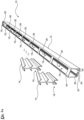
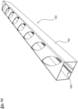
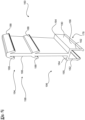
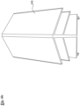
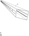
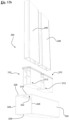
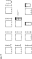
- Figures 1a to 1h provide several views of a panel mount 10 according to a first preferred embodiment of the present invention.
- the panel mount 10 has supports and fastening elements that are each advantageously manufactured as individual pieces in an extrusion process.
- the fastening elements are able to be positioned within the support at spaced apart locations there along.
- the fastening elements are readily positioned by pushing the fastening elements through spaced apart openings in the support.
- the fastening system is considered to be suited to the construction of fences, screens, roofing, awnings and many other structures. The applicability of the system is considered to extend beyond these fields.
- the panel mount 10 includes a support 12 and a plurality of fastening elements 14.
- Each fastening element 14 has a fastener-support mating portion 16 for engagement with a corresponding support-fastener mating portions 18 of the support 12.
- the support-fastener mating portions 18 are disposed along the support 12. More particularly each fastener-support mating portion 16 is configured for clip engagement with the corresponding support-fastener mating portion 18 of the support 12.
- the fastener-support mating portions 16 are provided as U-shaped structures each with two downwardly extending flanges that run along the length of the fastening element 14 on either side.
- the support-fastener mating portions 18 provide a channel 20 into which the faster-support mating portions 16 fit.
- the upper portion 22 accords with structures described in Australian Provisional Application 2016902172 .
- the upper portion 22 includes an extension 26 that extends upwardly from the lower portion 24.
- a number of downwardly extending side portions 28 extend from the extension 26.
- the lower portion 24 provides a base 30 from which two portions 32 extend downwardly.
- the base 30 is substantially perpendicular to the height of the fastening element 14.
- the lower portion 24 provides a portion that is able to mate with the support-fastener mating portions 18.
- the support-fastener mating portions 18 provide a continuous support-fastener mating portion 34.
- the continuous support fastener mating portion 34 spans the length of the support 12.
- the support 12 can be extruded as one length following which material can be removed to provide openings 36 spaced there along.
- the fastening elements 14 are able to be manufactured by the process of extrusion.
- the support 12 can be manufactured by the process of extrusion coupled with the provision of the openings 36 by milling or otherwise.
- Australian Provisional Application 2016902172 describes structures where the fastening elements 14 are integral with the support 12. The applicant is not aware of any systems having push fit fastening elements 14 that engage with a support 12 as described and which provide a fence, gate or otherwise.
- the fastener-support mating portions 16 each comprise a fastener-support mating portion 16 that provides a push fit portion 24 that is configured to be pushed towards the corresponding support-fastener mating portion 18 and engage therewith to hold the fastening element 14 to the support 12 .
- the push fit nature of the panel mount 10 is considered to be advantageous for the reason that no additional screws or rivets are required to secure the fastening elements 14 to the support 12 through the openings 36 .
- the ability to remove material only to the depth of the thickness of the side wall is also considered advantageous.
- the portions 32 each include a clip projection 40 that extends laterally away from the body of the lower portion 24 .
- the clip portions 38 each include a recess 42 into which the projections are received when the corresponding fastening element 14 is push fit into the support-fastener mating portion 18.
- the recesses 42 open laterally into the channel 20 .
- the support 12 comprises an elongate member having openings 36 spaced along the support 12 The openings are spaced along an elongate side 44 of the support 12 that is opposite the support-fastener mating portions 18.
- the fastener-support mating portions 16 are each pushed through a corresponding one of the openings 36 towards the corresponding support-fastener mating portion 18 and engage therewith to hold the fastening element 14 to the support 12.
- the person constructing the gate (or otherwise) holds a fastening element 14 in his or her hand, and forces the fastening element 14 through an opening 36 to engage with the support-fastener mating portion 18 thereby firmly holding the fasting element 14 to the support 12.
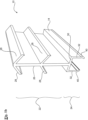
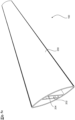
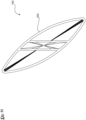
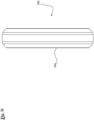
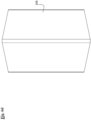
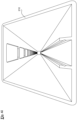
- Figure 1i illustrates a panel system 75 having fastening elements fixed to the support 12.
- the panel system 75 includes a support 12 and panel members 78 .
- the fixed fastening elements are not according to the invention and are present for illustrating the arrangement of the panel members 78 only.
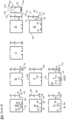
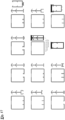
- the embodiment of Figure 2a includes a base 46 having arms 48 that are configured to clip into grooves 50 that are provided by two abutments 52 .
- the abutments 52 extend upwardly from a floor 54.
- the base includes downwardly facing portions 56 for resting on the upper face of the abutments 52.
- the embodiment of Figure 2g is similar to the embodiment of Figure 2a . In Figure 2a the base is however configured to rest on the upper surface 58 of the abutments.
- the fastener-support mating portion 60 comprises a base 62 having a number of clip portions 64 extending from opposite lateral sides of the base 62.
- the clip portions 64 are provided for engaging corresponding support-fastener mating portion 66 of the support 68 .
- FIG. 2f The embodiment of Figure 2f is somewhat similar to that of Figure 2b .
- the fastening element is inserted through an opening 100 that is provided on an opposite side of the support to the side having the support-fastener mating portions 102 .
- a corresponding I-shaped structure is provided in the mating portion 102 and the base 104 .
- Figure 2d shows a fastening element 118 and a fastening element 120 .
- the fastening element 120 has engagement portions 125 configured to provide an inwardly directed lateral engagement force to an additional support member that is connected to the end 122 spaced away from the fastener-support mating portions 124 . This is in comparison to the fastening element 118 which provides an outwardly directed lateral engagement force to an additional support member.
- the use of fastening element 120 is not presently preferred for the reason that scratching could be made to the outer surface of an additional support member when received within the fastening element 120 . Whilst the fastening elements having outwardly directed additional support member engaging portions are preferred, embodiments having inwardly directed engaging portions are possible.
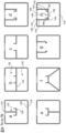
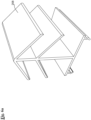
- Figures 3a to 3h illustrates support-fastener mating abutments that are positioned above the floor of the support member opposite the opening.
- the embodiment of Figure 3a illustrates a support-fastener mating abutment 126 that is positioned above the floor 128 of the support member 130.
- the support member 130 includes an extension 132 that extends along the support and which is milled out beneath each opening 134 . This allows a fastening element to be received between alternating extensions 132 within the support-fastening mating abutment 126.
- the embodiment of Figure 3b comprises an extension 136 that extends across the support to provide an upper channel area 138 and a lower channel area 140 .
- This provides a system similar to that shown in Figure 4 in that an upper and a lower channel area are provided.
- Embodiment having an upper channel area 138 and the lower channel area 140 are considered to be advantages for corner connections.
- the applicant is presently preparing a patent application directed to the provision of multiple channels.
- the double channel allows for a corner joint (as illustrated) to be provided in the lower channel area 140 beneath the support-fastener mating portion abutments which are disposed thereabove.
- the embodiment of Figure 3h provides a support 142 having a support-fastener mating portion 144 that provides a channel 146 having abutments 148 with clip portions in the form of two opposing grooves 150 both on inwardly facing sides.
- the channel 146 has a base 152 that holds the support-fastener mating portions 144 together when a corresponding fastening element is inserted in the channel 146 .
- Two portions 154 extend from the base 152 to the side 156 providing an opening 158 .. This is in comparison to Figure 3d wherein the side portions of the channel are not provided with a base that forms a closed channel beneath the openings.
- fastener-support mating portions provide a female clip and clip portions are provided on both outwardly facing sides of the channel.
- grooves comprises projections and the projections comprise grooves.
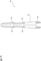
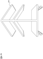
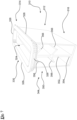
- FIGS 5a to 5l illustrate a fastening system 160 according to a further preferred embodiment of the present invention.
- a support 162 and a plurality of fastening elements 164 .
- Each fastening element 164 has a fastener-support mating portion 166 for engagement with a corresponding support-fastener mating portion 168 of the support 162 .
- the support 162 has the corresponding support-fastener mating portions 168 disposed therealong.
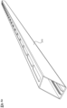
- the support comprises an elongate member having openings 170 spaced along the support 162 .
- the openings 170 are spaced along an elongate side 172 of the support 162 .
- An opposite side 174 provides the support-fastener mating portions 168 there along.
- Each fastener-support mating portion 166 has to be pushed through a corresponding opening 170 towards the corresponding support-fastener mating portion 168 and engage therewith to hold the fastener 164 to the support 162 . Removal of material from the extrusion of the support 162 only has to occur to the depth of the thickness of the elongate side 172 .
- the openings 170 comprises elliptically shaped openings 170 arranged at an angle to the length of support-fastener mating portions 168 .
- the length of support-fastener mating portions 168 provides two longitudinally extending substantially parallel abutments 176 that extend along the length of the support 162 .
- the fastener-support mating portions 166 each comprise a push fit portion that is configured to be pushed towards the corresponding support-fastener mating portion 168 and engage therewith to hold the fastening element 164 to the support 162 .
- Each fastener- support mating portion 166 and corresponding support-fastener mating portion 168 can be considered as providing a male clip portion 178 and a female clip portion 180 for clipping engagement.
- Mechanical inversions where fastener-support mating portion provides a female clip portion and the support-fastener mating portion 168 provides a male clip portion are of course possible.
- the male clip portion 178 can be considered as providing two longitudinally extending portions 190 that provide the arms 182 .
- the female clip portion 180 can be considered as comprising two longitudinally extending portions 192 for receiving the longitudinally extending portions 190 of the male clip portion 178 therebetween.
- the longitudinally extending portions 190 are spaced apart for clipping engagement between the longitudinally extending portions 192 .
- each of the portions 190 are configured to flex laterally inwardly and the portions 192 are configured to flex laterally outwardly as the male clip portion 178 is inserted into the female clip portion 180 .
- This is achieved by the provision of clip portions having surfaces that bear against each other and provide the clipping engagement.
- portions 190 and, 192 slide past one another and then clip in position by provision of the grooves and nibs (shown in the drawings). When fully inserted the portions 190 and 192 spring to their original positions, to which they are biased. As would be apparent various forms of clipping arrangements are possible.
- the arms 188 are configured to apply a holding force that is sufficient to hold the additional support 200 in position relative to the support 162 .
- the fastener-additional support mating portion 198 holds the additional support with the fastener-support mating portion 166 holding the support 162.
- the fastener-additional support mating portion 198 comprises an extension including the arms extending from the body of the extension towards the lateral boundary of the fastener. As described, the arms 188 are configured for bearing against the inner surfaces of an additional support to apply an engaging force in a direction laterally outwardly relative to the additional support.
- Each fastening element 164 is considered to provide an embodiment of the present invention in its own right.
- Figure 6a illustrates a fasting element 208 of a greater width to length ratio than those previously described.
- Figure 6e shows a support 210 that is considered to provide a further embodiment of the present invention in its own right.
- the supports in this embodiment provide panel members for forming gates and fences, where the panel members can be arranged to form gates and fences.
- Other embodiments may have the panel members at different angles as described in Australian Provisional Application 2016902172
- the fastening elements are provided with an arrow head and a U-shaped end.
- the base is able to be inserted through openings in the support to engage with the corresponding portions in the support.
- the provision of a U-shaped end is considered to be advantageous for the reason that a clear clipping effect is achieved on insertion.
- the provision of an arrow head is considered to be advantageous for the reason that the arrowhead is able to extend an appreciable distance into an additional support when inserted into a corresponding opening.
- Embodiments are being considered in which the U-shaped end is replaced with an arrowhead.
- the support fastener mating portions of the support that receive the U-shaped end can be manufactured to a sufficient tolerance quite readily. For this reason it is considered that replacing the U-shaped portions is undesirable.
- preferred embodiments of the present invention have a number of advantages, including the ability to manufacture channels and channel fastening elements as separate pieces for ready extrusion and for the fastening elements to be positioned within a support member at spaced apart locations therealong with the fastening elements being positioned by pushing the fastening elements through spaced apart openings of the support member.
- the fastening element 310 advantageously provides an element that engages side walls that provide the external periphery of a support. This is in distinction to engaging internal side walls that do not provide the external periphery of the support.
- the fastening element 310 is able to receive an additional support that is mounted by the fastening element 310 to the support.
- the body 312 of the fastening element 310 extends into the support 320 from the fastening end 314 (at the side wall 318 of the support) towards the opposite end 316.
- the fastening end provides an opening 324 for receiving an additional support.
- the fastening end 314 includes a rim 330 for engaging the side wall 318 of the support that provides the opening 322.
- the rim 330 comprises a lateral flange 332 that extends around the opening 324 that is provided for receiving the additional support.
- the lateral flange 332 comprises a C-shape opening extending laterally around the opening 324.
- the lateral flange 332 extends laterally away from the body 312 of the fastening element 310 and includes a channel 334 that faces laterally outwardly for receiving the side wall 318.
- the fastening element 310 may be extruded from materials including aluminium and plastics.
- the fastening element 310 may be extruded as one continuous length before the continuous length is machined to provide multiple fastening elements 310.
- the rim 330 is configured for collared engagement with the side wall 318 of the support.
- the collared engagement comprises providing an abutment 336 above the channel 334 and external to the body of the support 312.
- the collared engagement further provides abutment 338 internal to the body of the support, when the fastening end 314 engages the side wall 318.
- the abutment 338 is provided for flexing clip engagement when pushed through the opening 322.
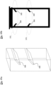
- the body 312 includes a number of side walls 342 extending from the fastening end 314 to the opposite end 316.
- the side walls 342 provide a casing 344 that limits the passage of dirt and other material beyond the fastening element 310 , into the further reaches of the support 320, when in a mounted position as shown in Figure 10 .
- the casing 434 is considered to possibly limit damage to additional supports 346 that are received by the casing 344 through the opening 324. This could be achieved by limiting lateral movement (relative to the fastening element).
- Figure 9b and Figure 9c provide additional views. Among other things, Figure 9b illustrates the side walls 342 and Figure 9c illustrates the opening 324.
- the side walls 342 comprise continuous side walls that provide the body 312 as a rectangularly shaped casing.
- the side walls 342 comprise two side walls 342 extending from the fastening end 314 to the opposite end 316 .
- the side walls 342 extend perpendicularly to the opposite end 316 and also across in the longitudinal direction of the body 312.
- a rear wall 348 provides a base.
- the side walls 342 provide a walled structure 350 assisting with limiting rotation of the additional support 346 when the additional support 346 is received through the opening 324 of the fastening end 314 and is held in position by an internal structure 352 .
- the internal structure 352 is provided in the form of a fastener-support mating portion 354.
- the walled structure 350 houses the fastener-support mating portion 354 for receiving the additional support 346.
- the fastener-support mating portion 354 includes a number of downwardly extending portions 356 for bearing against the internal surface 358 of the side walls 360 of the additional support 346 .
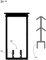
- FIG 14 illustrates a further preferred embodiment of the present invention where the rear wall 348 provides a number of casing-fastener mating portions 362 for a fastener element 364.
- the casing-fastening mating portions 362 comprise a pair of elements 366 spaced apart towards the opposite end.
- fastener-support mating portions 368 comprising a number of elements extending away from the side walls of the body providing the walled structure.
- the fastener-support mating portions 368 are provided for bearing against the outer surface of an additional support.
- the fastener-support mating portions 368 are not preferred as they would scratch the outer surface of the additional support.
- the fastener-support mating portions 368 extend from the side wall of the walled structure in a direction laterally into the body and towards the opposite end of the body away from the fastening end.
- the fastener-support mating portions 368 provide two pairs 370 of elements spaced apart towards the opposite end. Each pair of elements comprises a first element on a side wall of the body and a second element on an opposite side wall of the body facing towards the first element.
- the side wall and the opposite side wall of the body extend along the support.
- the fastener-support mating portion 354 is configured to provide an arrow structure having a number of elements 356 extending toward the side walls 342 of the body in a direction laterally outwardly and downwardly towards the opposite end 316 of the body 312 .
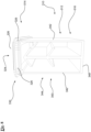
- a fastening system 380 comprising: a support 320 and a plurality of fastening elements 310.
- Each fastening element 310 comprising: a body 312 having a fastening end 314 and an opposite end 316.
- the fastening end 314 is configured for engaging a side wall 318 of the elongate support with the body of the fastening element 310 extending into the support 320 towards the opposite end 316.
- the fastening end 314 is provided for receiving an additional support 346 .
- FIGS 17 to 20 illustrate further various fastening elements.
Landscapes
- Engineering & Computer Science (AREA)
- Architecture (AREA)
- Civil Engineering (AREA)
- Structural Engineering (AREA)
- General Engineering & Computer Science (AREA)
- Electromagnetism (AREA)
- Physics & Mathematics (AREA)
- Mechanical Engineering (AREA)
- Connection Of Plates (AREA)
- Insertion Pins And Rivets (AREA)
- Panels For Use In Building Construction (AREA)
- Supports For Pipes And Cables (AREA)
- Clamps And Clips (AREA)
Claims (5)
- Eine Paneelhalterung (10), umfassend einen Träger (12, 68, 130, 142, 162, 210, 320); eine Vielzahl von entlang des Trägers (12, 68, 130, 142, 162, 210, 320) beabstandeten Befestigungselementen (14, 70, 98, 118, 120, 164, 310); wobei jedes Befestigungselement (14, 70, 98, 118, 120, 164, 310) einen Befestigungselement-Träger-Paarungsabschnitt (16, 60, 24, 166, 326, 354, 368, 374) zum Eingriff mit einem entsprechenden Träger-Befestigungselement-Paarungsabschnitt (18, 34, 66, 102, 106, 144, 168, 376) des Trägers (12, 68, 130, 142, 162, 210, 320) aufweist; wobei der Träger (12, 68, 130, 142, 162, 210, 320) die entsprechenden Träger-Befestigungselement-Paarungsabschnitte (18, 34, 66, 102, 106, 144, 168, 376) an ihm entlang angeordnet aufweist, wobei jedes Befestigungselement(14, 70, 98, 118, 120, 164, 310) zum derartigen Einwirken auf mindestens eine Innenfläche eines Paneelelements (78, 200) ausgelegt ist, dass es eine Einwirkungskraft aufbringt, die relativ zu dem Paneelelement (78, 200) seitlich nach außen gerichtet ist, wenn auf das Paneelelement (78, 200) durch das Befestigungselement (14, 70, 98, 118, 120, 164, 310) eingewirkt wird, wobei jedes Befestigungselement (14, 70, 98, 118, 120, 164, 310) ein erstes Ende (194) mit einer Verlängerung (26, 132, 136, 186, 198) umfasst, wobei die Verlängerung (26, 132, 136, 186, 198) mindestens zwei Gruppen von nach unten gerichteten Verlängerungen (28, 188, 208, 356) umfasst, die sich in unterschiedlichen Höhen vom Körper der Verlängerung (26, 132, 136, 186, 198) nach unten zu Längsseiten eines Paneelelements (78, 200) derart hin erstrecken, dass sie an Innenflächen (204) des Paneelelements (78, 200) derart anliegen, dass sie eine Einwirkungskraft in einer Richtung seitlich nach außen relativ zu dem Paneelelement (78, 200) aufbringen, wobei das Befestigungselement (14, 70, 98, 118, 120, 164, 310) an einem zweiten Ende (196) den Befestigungselement-Träger-Paarungsabschnitt (16, 60, 24, 166, 326, 354, 368, 374) zum Eingriff mit dem entsprechenden Träger-Befestigungselement-Paarungsabschnitt (18, 34, 66, 102, 106, 144, 168, 376) des Trägers (12, 68, 130, 142, 162, 210, 320) aufweist, wobei der Träger (12, 68, 130, 142, 162, 210, 320) entlang des Trägers (12, 68, 130, 142, 162, 210, 320) beabstandete Öffnungen (36, 100, 116, 134, 158, 170, 322) aufweist; dadurch gekennzeichnet, dass die Öffnungen (36, 100, 116, 134, 158, 170, 322) entlang einer den Träger-Befestigungselement-Paarungsabschnitten (18, 34, 66, 102, 106, 144, 168, 376) gegenüberliegenden langgestreckten Seite des Trägers (12, 68, 130, 142, 162, 210, 320) voneinander beabstandet sind; wobei jedes Befestigungselement (14, 70, 98, 118, 120, 164, 310) durch eine entsprechende der Öffnungen (36, 100, 116, 134, 158, 170, 322) in Richtung des entsprechenden Träger-Befestigungselement-Paarungsabschnitts (18, 34, 66, 102, 106, 144, 168, 376) gedrückt werden und damit in Eingriff kommen muss, um das Befestigungselement (14, 70, 98, 118, 120, 164, 310) gegen den Träger (12, 68, 130, 142, 162, 210, 320) zu halten, und jedes Befestigungselement (14, 70, 98, 118, 120, 164, 310) ein Paneelelement (78, 200) aufnimmt, das sich durch die zugeordnete Öffnung (36, 100, 116, 134, 158, 170, 322) des Trägers (12, 68, 130, 142, 162, 210, 320) erstreckt.
- Paneelhalterung (10) nach Anspruch 1, wobei die Paneelhalterung (10) wiederverwendbar ist, wobei jedes Befestigungselement (14, 70, 98, 118, 120, 164, 310) von einem Paneelelement (78, 200) abnehmbar ist, damit das Befestigungselement (14, 70, 98, 118, 120, 164, 310) bei einem anderen Paneelelement (78, 200) verwendet werden kann, und wobei jedes Befestigungselement (14, 70, 98, 118, 120, 164, 310) eine sich von dem Träger (12, 68, 130, 142, 162, 210, 320) der Paneelhalterung (10) nach oben erstreckende Verlängerung (26, 132, 136, 186, 198) umfasst, wobei die Verlängerung (26, 132, 136, 186, 198) sich von dem Körper der Verlängerung (26, 132, 136, 186, 198) zu den Längsseiten des Trägers (12, 68, 130, 142, 162, 210, 320) erstreckende Seitenabschnitte (28, 188, 208, 356) umfasst; wobei die Seitenabschnitte (28, 188, 208, 356) zum Anliegen an den Innenflächen des Paneelelements (78, 200) vorgesehen sind, um die Einwirkungskraft in einer Richtung seitlich nach außen relativ zum Paneelelement (78, 200) aufzubringen.
- Paneelhalterung (10) nach Anspruch 1, wobei die Befestigungselement-Träger-Paarungsabschnitte (16, 60, 24, 166, 326, 354, 368, 374) jeweils einen Steckpassungsabschnitt (24, 166) umfassen, der dazu ausgelegt ist, in Richtung des entsprechenden Träger-Befestigungselement-Paarungsabschnitts (18, 34, 66, 102, 106, 144, 168, 376) gedrückt zu werden und mit diesem derart in Eingriff zu kommen, dass das Befestigungselement (14, 70, 98, 118, 120, 164, 310) gegen den Träger (12, 68, 130, 142, 162, 210, 320) gehalten wird.
- Paneelhalterung (10) nach einem der vorhergehenden Ansprüche, wobei die Befestigungselement-Träger-Paarungsabschnitte (16, 60, 24, 166, 326, 354, 368, 374) jeweils einen Steckpassungsabschnitt (24, 166) umfassen, der dazu ausgelegt ist, in Richtung des entsprechenden Träger-Befestigungselement-Paarungsabschnitts (18, 34, 66, 102, 106, 144, 168, 376) gedrückt zu werden und mit diesem derart in Eingriff zu kommen, dass das Befestigungselement (14, 70, 98, 118, 120, 164, 310) gegen den Träger (12, 68, 130, 142, 162, 210, 320) gehalten wird; wobei jeder Befestigungselement-Träger-Paarungsabschnitt (16, 60, 24, 166, 326, 354, 368, 374) und entsprechende Träger-Befestigungselement-Paarungsabschnitt (18, 34, 66, 102, 106, 144, 168, 376) einen Klammersteckabschnitt (32, 64, 94, 178) und einen Klammeraufnahmeabschnitt (38, 66, 90, 180) für den klammernden Eingriff bereitstellen.
- Paneelhalterung (10) nach Anspruch 4, wobei jeder Klammersteckabschnitt (32, 64, 94, 178) zwei sich in Längsrichtung erstreckende Abschnitte (40, 64, 94, 190) aufweist und der entsprechende Aufnahmeabschnitt (38, 66, 90, 180) zwei sich in Längsrichtung erstreckende Abschnitte (38, 66, 96, 192) zur Aufnahme der sich in Längsrichtung erstreckenden Abschnitte (40, 64, 94, 190) des Klammersteckabschnitts (32, 64, 94, 178) zwischen ihnen aufweist.
Applications Claiming Priority (4)
| Application Number | Priority Date | Filing Date | Title |
|---|---|---|---|
| AU2016902172A AU2016902172A0 (en) | 2016-06-03 | Panel systems and components | |
| AU2017901618A AU2017901618A0 (en) | 2017-05-04 | Panel systems and components – separate fastener | |
| AU2017901619A AU2017901619A0 (en) | 2017-05-04 | Panel systems and components – cartridge | |
| PCT/AU2017/050544 WO2017205940A1 (en) | 2016-06-03 | 2017-06-03 | Panel systems and components |
Publications (4)
| Publication Number | Publication Date |
|---|---|
| EP3464758A1 EP3464758A1 (de) | 2019-04-10 |
| EP3464758A4 EP3464758A4 (de) | 2020-03-04 |
| EP3464758C0 EP3464758C0 (de) | 2025-04-16 |
| EP3464758B1 true EP3464758B1 (de) | 2025-04-16 |
Family
ID=60479603
Family Applications (1)
| Application Number | Title | Priority Date | Filing Date |
|---|---|---|---|
| EP17805420.1A Active EP3464758B1 (de) | 2016-06-03 | 2017-06-03 | Plattensysteme und -komponenten |
Country Status (7)
| Country | Link |
|---|---|
| US (1) | US11549279B2 (de) |
| EP (1) | EP3464758B1 (de) |
| CN (1) | CN109715897A (de) |
| AU (1) | AU2017274579B2 (de) |
| CA (1) | CA3025670C (de) |
| ES (1) | ES3035242T3 (de) |
| WO (1) | WO2017205940A1 (de) |
Families Citing this family (7)
| Publication number | Priority date | Publication date | Assignee | Title |
|---|---|---|---|---|
| NZ769678A (en) | 2018-05-07 | 2025-10-31 | Tomm Tech Pty Ltd | Mitre joint support |
| US12246419B2 (en) | 2018-05-07 | 2025-03-11 | Tomm Tech Pty Ltd | Mitre joint support |
| AU2019277270B8 (en) * | 2018-06-01 | 2025-08-07 | Sas Systems Australia Pty Ltd | Assembly and method for attaching extruded members |
| US20220372785A1 (en) * | 2021-05-14 | 2022-11-24 | Tiao-Chin Lin | Fencing assembly |
| CN113618376B (zh) * | 2021-08-23 | 2022-07-12 | 舒城恒康儿童用品有限公司 | 一种木制隔栅自动组装装置 |
| US11828068B2 (en) * | 2021-11-24 | 2023-11-28 | Novo Building Products, Llc | Baluster attachment mechanism having securing resilient flanges |
| US12421756B2 (en) * | 2022-10-27 | 2025-09-23 | Barrette Outdoor Living, Inc. | Decorative topper system and method |
Citations (1)
| Publication number | Priority date | Publication date | Assignee | Title |
|---|---|---|---|---|
| US20090282772A1 (en) * | 2008-05-13 | 2009-11-19 | Ged Integrated Solutions, Inc. | Multiple configuration joiner clip |
Family Cites Families (48)
| Publication number | Priority date | Publication date | Assignee | Title |
|---|---|---|---|---|
| US3498589A (en) | 1967-08-30 | 1970-03-03 | Railtec Corp | Interlocking railing construction |
| FR2034361B1 (de) * | 1969-03-20 | 1976-07-23 | Lembo Bernard | |
| FR2250877A1 (en) * | 1973-11-14 | 1975-06-06 | Elmaduc | Device for fixing hand-rail to an upright - has two arms expanded within the upright by a screw |
| US4014520A (en) * | 1975-12-22 | 1977-03-29 | Walters Donald H | Railing assembly and method |
| US4073477A (en) * | 1976-09-13 | 1978-02-14 | Walters Donald H | Railing with interfitting rectangular and curved cross section members |
| DE2904520A1 (de) | 1979-02-07 | 1980-08-21 | Erich Ing Grad Amrogowicz | Verbindung von annaehernd lotrecht aufeinanderstossenden hohlen profilholmen |
| US4568215A (en) * | 1983-11-21 | 1986-02-04 | Illinois Tool Works Inc. | Laterally adjustable fastening assembly |
| US4725044A (en) * | 1986-11-18 | 1988-02-16 | Cluff Robert G | Chain link fencing containing decorative slats and locking clips |
| US4805879A (en) * | 1987-12-09 | 1989-02-21 | Vittorio Spera | Hand railing assembly |
| US5234199A (en) * | 1988-08-29 | 1993-08-10 | Cluff Robert G | Chain link fencing with decorative slats |
| US4995591A (en) * | 1989-05-26 | 1991-02-26 | Humphrey William D | Retaining lock for chain link fence slats |
| US4950098A (en) * | 1989-06-16 | 1990-08-21 | Vip Company | Slat fence retainer |
| US5275381A (en) * | 1991-09-26 | 1994-01-04 | Cluff Robert G | Wire fencing with decorative slats that provide essentially complete privacy |
| US5313761A (en) * | 1992-01-29 | 1994-05-24 | Glass Equipment Development, Inc. | Insulating glass unit |
| US5873564A (en) * | 1994-11-25 | 1999-02-23 | Bisch; Robert M. | Method and apparatus for constructing a metal picket fence |
| US5651534A (en) * | 1995-04-03 | 1997-07-29 | Ctb, Inc. | Modular fencing system |
| DE29516458U1 (de) * | 1995-10-17 | 1996-05-15 | Johannes Sörnsen, Holzleisten, Inh. Georg Sörnsen, 24392 Süderbrarup | Eine unsichtbare Halterung zur Befestigung von Leisten aller Art, an Wänden, Schränken, Blechen o.ä. |
| US5678376A (en) * | 1995-10-30 | 1997-10-21 | Poma; James P. | Universal intercept clip |
| US6568658B2 (en) * | 2000-12-22 | 2003-05-27 | Craneveyor Corporation | Quick-connect railing connector |
| US6631887B1 (en) * | 2001-05-14 | 2003-10-14 | Roger Walmsley | Vertical fencing |
| US6651400B1 (en) * | 2001-10-18 | 2003-11-25 | Rapid Displays, Inc. | Foam core panel connector |
| US20030201432A1 (en) * | 2002-04-26 | 2003-10-30 | Jeff Norman | Modular railing and related methods |
| US8113489B1 (en) * | 2002-10-15 | 2012-02-14 | Harder Willard J | Rail |
| US6932329B1 (en) * | 2002-10-15 | 2005-08-23 | Willard J. Harder | Railing |
| CA2502884C (en) * | 2002-10-22 | 2010-12-21 | Sashlite, Llc | Grid muntin retaining clips for muntins |
| US6971831B2 (en) * | 2003-04-16 | 2005-12-06 | Lmt Mercer Group, Inc. | Self-locking fastener |
| US20050098771A1 (en) * | 2003-11-10 | 2005-05-12 | Demaere Roch | Slat System for Picket Barriers |
| HUE030527T2 (en) * | 2004-11-03 | 2017-05-29 | Edgetech I G Inc | Window splitting clamp and method for its application |
| US7685782B2 (en) * | 2004-12-10 | 2010-03-30 | Newell Operating Company | Muntin clip |
| US7232114B2 (en) * | 2005-06-02 | 2007-06-19 | Platt Robert E | Fence assembly with rail clip for use therewith |
| US20070158630A1 (en) * | 2005-12-14 | 2007-07-12 | Chong-Yi Lo | Post and rod linking device for a railing |
| US7475870B2 (en) * | 2005-12-22 | 2009-01-13 | Platt Robert E | Method and apparatus for mounting angled fence portions |
| US8001742B2 (en) * | 2006-08-16 | 2011-08-23 | Ged Integrated Solutions, Inc. | Muntin bar clip and muntin bar assembly |
| AU2006230672B1 (en) * | 2006-10-18 | 2007-04-26 | Alan Brownbill | A Panel |
| US8033530B2 (en) * | 2008-01-04 | 2011-10-11 | Nationwide Industries, Inc. | Stair rail assembly |
| US20090272957A1 (en) * | 2008-05-01 | 2009-11-05 | Strongwell Corporation | Connector for railing systems |
| AU2009100361A4 (en) * | 2009-04-21 | 2009-05-28 | Singh Fabrications Pty Ltd | Modular panel construction |
| US20110127482A1 (en) * | 2009-12-02 | 2011-06-02 | Chong-Yi Lo | Combined structure of fence posts and rails |
| DE202012102484U1 (de) * | 2012-07-05 | 2013-10-08 | Rehau Ag + Co | Verbindungsanordnung |
| US9027909B1 (en) * | 2013-05-24 | 2015-05-12 | Origin Point Brands, Llc | Rackable screwless fencing system |
| US9133645B2 (en) * | 2013-10-04 | 2015-09-15 | AGS Stainless, Inc. | Rod fittings and assemblies |
| US9790689B2 (en) * | 2013-10-16 | 2017-10-17 | Universal Consumer Products, Inc. | Baluster connector |
| US9637932B2 (en) | 2013-10-30 | 2017-05-02 | Barrette Outdoor Living, Inc. | Railing and baluster plug system |
| US9908207B2 (en) * | 2014-03-05 | 2018-03-06 | Russell H. Springborn | In-rail connector |
| CA2914022A1 (en) * | 2014-12-05 | 2016-06-05 | Universal Consumer Products, Inc. | Baluster connector |
| US10060136B2 (en) * | 2014-12-09 | 2018-08-28 | Universal Consumer Products, Inc. | Baluster connector |
| DE202015005204U1 (de) * | 2015-07-21 | 2015-10-28 | Holger Neisser | Zaunpfosten- und Verbindungssystem für Flachstabgittermatten |
| AU2017200366B2 (en) | 2016-01-19 | 2022-09-15 | Sas Systems Australia Pty Ltd | A lockbox for a lock mechanism |
-
2017
- 2017-06-03 AU AU2017274579A patent/AU2017274579B2/en active Active
- 2017-06-03 WO PCT/AU2017/050544 patent/WO2017205940A1/en not_active Ceased
- 2017-06-03 CN CN201780048138.0A patent/CN109715897A/zh active Pending
- 2017-06-03 CA CA3025670A patent/CA3025670C/en active Active
- 2017-06-03 ES ES17805420T patent/ES3035242T3/es active Active
- 2017-06-03 EP EP17805420.1A patent/EP3464758B1/de active Active
-
2018
- 2018-12-03 US US16/207,682 patent/US11549279B2/en active Active
Patent Citations (1)
| Publication number | Priority date | Publication date | Assignee | Title |
|---|---|---|---|---|
| US20090282772A1 (en) * | 2008-05-13 | 2009-11-19 | Ged Integrated Solutions, Inc. | Multiple configuration joiner clip |
Also Published As
| Publication number | Publication date |
|---|---|
| CA3025670A1 (en) | 2017-12-07 |
| CN109715897A (zh) | 2019-05-03 |
| US20190136573A1 (en) | 2019-05-09 |
| CA3025670C (en) | 2023-07-04 |
| NZ749392A (en) | 2024-03-22 |
| AU2017274579A1 (en) | 2019-01-17 |
| US11549279B2 (en) | 2023-01-10 |
| EP3464758A1 (de) | 2019-04-10 |
| EP3464758A4 (de) | 2020-03-04 |
| WO2017205940A1 (en) | 2017-12-07 |
| EP3464758C0 (de) | 2025-04-16 |
| ES3035242T3 (en) | 2025-09-01 |
| AU2017274579B2 (en) | 2022-03-24 |
Similar Documents
| Publication | Publication Date | Title |
|---|---|---|
| EP3464758B1 (de) | Plattensysteme und -komponenten | |
| US12429251B2 (en) | Multi-level mounting system | |
| US5203132A (en) | Wall assembly | |
| US9869096B2 (en) | Modular surface covering assembly to cover a bearing surface | |
| US8925271B1 (en) | System for mounting wall panels to a wall structure | |
| US6036398A (en) | Extruded frame member for structural connection and method of forming same | |
| US9850666B2 (en) | Panel system for covering a building wall | |
| CA2645824C (en) | Improved connections for suspended ceiling system | |
| WO2018201203A1 (en) | Panel systems and components | |
| AU2011340798B2 (en) | Fencing panel | |
| US4917528A (en) | Panel joint | |
| US12215725B2 (en) | Gripping bracket | |
| AU2010201523A1 (en) | A Floor Trim System | |
| CN215563842U (zh) | 一种容易组装的钢材组件 | |
| US20170122349A1 (en) | Baggage door | |
| EP2696020B1 (de) | Koppler | |
| AU2016203546B2 (en) | A frame to receive a mesh panel | |
| GB2440335A (en) | Fixing apparatus used in the assembly of fences | |
| GB2407339A (en) | Glazing assembly | |
| EP3239424A1 (de) | Rahmenelement, verbindungselement und system mit mindestens einem rahmenelement und einem verbindungselement | |
| HK1133058A (en) | Modular cabinet, components therefor, kit and method |
Legal Events
| Date | Code | Title | Description |
|---|---|---|---|
| STAA | Information on the status of an ep patent application or granted ep patent |
Free format text: STATUS: THE INTERNATIONAL PUBLICATION HAS BEEN MADE |
|
| PUAI | Public reference made under article 153(3) epc to a published international application that has entered the european phase |
Free format text: ORIGINAL CODE: 0009012 |
|
| STAA | Information on the status of an ep patent application or granted ep patent |
Free format text: STATUS: REQUEST FOR EXAMINATION WAS MADE |
|
| 17P | Request for examination filed |
Effective date: 20190103 |
|
| AK | Designated contracting states |
Kind code of ref document: A1 Designated state(s): AL AT BE BG CH CY CZ DE DK EE ES FI FR GB GR HR HU IE IS IT LI LT LU LV MC MK MT NL NO PL PT RO RS SE SI SK SM TR |
|
| AX | Request for extension of the european patent |
Extension state: BA ME |
|
| DAV | Request for validation of the european patent (deleted) | ||
| DAX | Request for extension of the european patent (deleted) | ||
| A4 | Supplementary search report drawn up and despatched |
Effective date: 20200205 |
|
| RIC1 | Information provided on ipc code assigned before grant |
Ipc: E04D 3/00 20060101ALI20200130BHEP Ipc: B23P 19/02 20060101ALI20200130BHEP Ipc: E04B 2/74 20060101ALI20200130BHEP Ipc: E04H 17/14 20060101AFI20200130BHEP Ipc: E04D 12/00 20060101ALI20200130BHEP Ipc: E04B 9/06 20060101ALI20200130BHEP Ipc: F16B 7/04 20060101ALI20200130BHEP Ipc: F16B 9/02 20060101ALI20200130BHEP Ipc: E04B 7/00 20060101ALI20200130BHEP Ipc: E04C 2/30 20060101ALI20200130BHEP Ipc: E04F 11/18 20060101ALI20200130BHEP Ipc: F16B 2/20 20060101ALI20200130BHEP Ipc: E04F 15/02 20060101ALI20200130BHEP Ipc: E06B 9/00 20060101ALI20200130BHEP Ipc: E04F 10/00 20060101ALI20200130BHEP Ipc: E04B 9/34 20060101ALI20200130BHEP Ipc: E04B 1/18 20060101ALI20200130BHEP Ipc: F16B 2/02 20060101ALI20200130BHEP Ipc: E04C 5/16 20060101ALI20200130BHEP Ipc: E04B 2/72 20060101ALI20200130BHEP |
|
| STAA | Information on the status of an ep patent application or granted ep patent |
Free format text: STATUS: EXAMINATION IS IN PROGRESS |
|
| 17Q | First examination report despatched |
Effective date: 20201204 |
|
| GRAP | Despatch of communication of intention to grant a patent |
Free format text: ORIGINAL CODE: EPIDOSNIGR1 |
|
| STAA | Information on the status of an ep patent application or granted ep patent |
Free format text: STATUS: GRANT OF PATENT IS INTENDED |
|
| INTG | Intention to grant announced |
Effective date: 20241210 |
|
| GRAS | Grant fee paid |
Free format text: ORIGINAL CODE: EPIDOSNIGR3 |
|
| GRAA | (expected) grant |
Free format text: ORIGINAL CODE: 0009210 |
|
| STAA | Information on the status of an ep patent application or granted ep patent |
Free format text: STATUS: THE PATENT HAS BEEN GRANTED |
|
| AK | Designated contracting states |
Kind code of ref document: B1 Designated state(s): AL AT BE BG CH CY CZ DE DK EE ES FI FR GB GR HR HU IE IS IT LI LT LU LV MC MK MT NL NO PL PT RO RS SE SI SK SM TR |
|
| REG | Reference to a national code |
Ref country code: GB Ref legal event code: FG4D |
|
| RIN1 | Information on inventor provided before grant (corrected) |
Inventor name: HODGSON, RILEY Inventor name: HODGSON, THOMAS |
|
| REG | Reference to a national code |
Ref country code: CH Ref legal event code: EP Ref country code: DE Ref legal event code: R096 Ref document number: 602017088962 Country of ref document: DE |
|
| REG | Reference to a national code |
Ref country code: IE Ref legal event code: FG4D |
|
| U01 | Request for unitary effect filed |
Effective date: 20250513 |
|
| U07 | Unitary effect registered |
Designated state(s): AT BE BG DE DK EE FI FR IT LT LU LV MT NL PT RO SE SI Effective date: 20250519 |
|
| U20 | Renewal fee for the european patent with unitary effect paid |
Year of fee payment: 9 Effective date: 20250526 |
|
| REG | Reference to a national code |
Ref country code: ES Ref legal event code: FG2A Ref document number: 3035242 Country of ref document: ES Kind code of ref document: T3 Effective date: 20250901 |
|
| PG25 | Lapsed in a contracting state [announced via postgrant information from national office to epo] |
Ref country code: GR Free format text: LAPSE BECAUSE OF FAILURE TO SUBMIT A TRANSLATION OF THE DESCRIPTION OR TO PAY THE FEE WITHIN THE PRESCRIBED TIME-LIMIT Effective date: 20250717 Ref country code: NO Free format text: LAPSE BECAUSE OF FAILURE TO SUBMIT A TRANSLATION OF THE DESCRIPTION OR TO PAY THE FEE WITHIN THE PRESCRIBED TIME-LIMIT Effective date: 20250716 |
|
| PG25 | Lapsed in a contracting state [announced via postgrant information from national office to epo] |
Ref country code: PL Free format text: LAPSE BECAUSE OF FAILURE TO SUBMIT A TRANSLATION OF THE DESCRIPTION OR TO PAY THE FEE WITHIN THE PRESCRIBED TIME-LIMIT Effective date: 20250416 |
|
| PGFP | Annual fee paid to national office [announced via postgrant information from national office to epo] |
Ref country code: GB Payment date: 20250728 Year of fee payment: 9 |
|
| PG25 | Lapsed in a contracting state [announced via postgrant information from national office to epo] |
Ref country code: HR Free format text: LAPSE BECAUSE OF FAILURE TO SUBMIT A TRANSLATION OF THE DESCRIPTION OR TO PAY THE FEE WITHIN THE PRESCRIBED TIME-LIMIT Effective date: 20250416 |
|
| PG25 | Lapsed in a contracting state [announced via postgrant information from national office to epo] |
Ref country code: RS Free format text: LAPSE BECAUSE OF FAILURE TO SUBMIT A TRANSLATION OF THE DESCRIPTION OR TO PAY THE FEE WITHIN THE PRESCRIBED TIME-LIMIT Effective date: 20250716 |
|
| PGFP | Annual fee paid to national office [announced via postgrant information from national office to epo] |
Ref country code: IE Payment date: 20250825 Year of fee payment: 9 |
|
| PG25 | Lapsed in a contracting state [announced via postgrant information from national office to epo] |
Ref country code: IS Free format text: LAPSE BECAUSE OF FAILURE TO SUBMIT A TRANSLATION OF THE DESCRIPTION OR TO PAY THE FEE WITHIN THE PRESCRIBED TIME-LIMIT Effective date: 20250816 |
|
| REG | Reference to a national code |
Ref country code: CH Ref legal event code: U11 Free format text: ST27 STATUS EVENT CODE: U-0-0-U10-U11 (AS PROVIDED BY THE NATIONAL OFFICE) Effective date: 20251113 |