EP4236550B1 - Verfahren, infrastrukturausrüstung und kommunikationsvorrichtung - Google Patents
Verfahren, infrastrukturausrüstung und kommunikationsvorrichtung Download PDFInfo
- Publication number
- EP4236550B1 EP4236550B1 EP23178306.9A EP23178306A EP4236550B1 EP 4236550 B1 EP4236550 B1 EP 4236550B1 EP 23178306 A EP23178306 A EP 23178306A EP 4236550 B1 EP4236550 B1 EP 4236550B1
- Authority
- EP
- European Patent Office
- Prior art keywords
- slot
- configuration information
- symbols
- slot configuration
- communications device
- Prior art date
- Legal status (The legal status is an assumption and is not a legal conclusion. Google has not performed a legal analysis and makes no representation as to the accuracy of the status listed.)
- Active
Links
Images


Classifications
-
- H—ELECTRICITY
- H04—ELECTRIC COMMUNICATION TECHNIQUE
- H04W—WIRELESS COMMUNICATION NETWORKS
- H04W72/00—Local resource management
- H04W72/20—Control channels or signalling for resource management
- H04W72/23—Control channels or signalling for resource management in the downlink direction of a wireless link, i.e. towards a terminal
-
- H—ELECTRICITY
- H04—ELECTRIC COMMUNICATION TECHNIQUE
- H04L—TRANSMISSION OF DIGITAL INFORMATION, e.g. TELEGRAPHIC COMMUNICATION
- H04L5/00—Arrangements affording multiple use of the transmission path
- H04L5/0001—Arrangements for dividing the transmission path
- H04L5/0003—Two-dimensional division
- H04L5/0005—Time-frequency
- H04L5/0007—Time-frequency the frequencies being orthogonal, e.g. OFDM(A) or DMT
-
- H—ELECTRICITY
- H04—ELECTRIC COMMUNICATION TECHNIQUE
- H04L—TRANSMISSION OF DIGITAL INFORMATION, e.g. TELEGRAPHIC COMMUNICATION
- H04L5/00—Arrangements affording multiple use of the transmission path
- H04L5/003—Arrangements for allocating sub-channels of the transmission path
- H04L5/0053—Allocation of signalling, i.e. of overhead other than pilot signals
-
- H—ELECTRICITY
- H04—ELECTRIC COMMUNICATION TECHNIQUE
- H04L—TRANSMISSION OF DIGITAL INFORMATION, e.g. TELEGRAPHIC COMMUNICATION
- H04L5/00—Arrangements affording multiple use of the transmission path
- H04L5/0091—Signalling for the administration of the divided path, e.g. signalling of configuration information
- H04L5/0094—Indication of how sub-channels of the path are allocated
-
- H—ELECTRICITY
- H04—ELECTRIC COMMUNICATION TECHNIQUE
- H04L—TRANSMISSION OF DIGITAL INFORMATION, e.g. TELEGRAPHIC COMMUNICATION
- H04L5/00—Arrangements affording multiple use of the transmission path
- H04L5/003—Arrangements for allocating sub-channels of the transmission path
- H04L5/0044—Allocation of payload; Allocation of data channels, e.g. PDSCH or PUSCH
-
- H—ELECTRICITY
- H04—ELECTRIC COMMUNICATION TECHNIQUE
- H04L—TRANSMISSION OF DIGITAL INFORMATION, e.g. TELEGRAPHIC COMMUNICATION
- H04L5/00—Arrangements affording multiple use of the transmission path
- H04L5/0091—Signalling for the administration of the divided path, e.g. signalling of configuration information
- H04L5/0092—Indication of how the channel is divided
-
- H—ELECTRICITY
- H04—ELECTRIC COMMUNICATION TECHNIQUE
- H04L—TRANSMISSION OF DIGITAL INFORMATION, e.g. TELEGRAPHIC COMMUNICATION
- H04L5/00—Arrangements affording multiple use of the transmission path
- H04L5/14—Two-way operation using the same type of signal, i.e. duplex
- H04L5/1469—Two-way operation using the same type of signal, i.e. duplex using time-sharing
-
- H—ELECTRICITY
- H04—ELECTRIC COMMUNICATION TECHNIQUE
- H04W—WIRELESS COMMUNICATION NETWORKS
- H04W72/00—Local resource management
- H04W72/04—Wireless resource allocation
- H04W72/044—Wireless resource allocation based on the type of the allocated resource
- H04W72/0446—Resources in time domain, e.g. slots or frames
Definitions
- the present disclosure relates to infrastructure equipment and communications devices of communications systems, where multiple methods may be used to configured slot structures of transmissions between the infrastructure equipment and communications devices as defined in the appended claims.
- Third and fourth generation mobile telecommunication systems such as those based on the 3GPP defined UMTS and Long Term Evolution (LTE) architecture, are able to support more sophisticated services than simple voice and messaging services offered by previous generations of mobile telecommunication systems.
- LTE Long Term Evolution
- a user is able to enjoy high data rate applications such as mobile video streaming and mobile video conferencing that would previously only have been available via a fixed line data connection.
- the demand to deploy such networks is therefore strong and the coverage area of these networks, i.e. geographic locations where access to the networks is possible, may be expected to increase ever more rapidly.
- Future wireless communications networks will be expected to routinely and efficiently support communications with a wider range of devices associated with a wider range of data traffic profiles and types than current systems are optimised to support. For example it is expected future wireless communications networks will be expected to efficiently support communications with devices including reduced complexity devices, machine type communication (MTC) devices, high resolution video displays, virtual reality headsets and so on. Some of these different types of devices may be deployed in very large numbers, for example low complexity devices for supporting the "The Internet of Things", and may typically be associated with the transmissions of relatively small amounts of data with relatively high latency tolerance.
- MTC machine type communication
- US2017/064729 discloses inter-access terminal unblocking and enhanced contention for co-existence on a shared communication medium.
- Figure 1 provides a schematic diagram illustrating some basic functionality of a mobile telecommunications network / system 10 operating generally in accordance with LTE principles, but which may also support other radio access technologies, and which may be adapted to implement embodiments of the disclosure as described herein.
- Various elements of Figure 1 and certain aspects of their respective modes of operation are well-known and defined in the relevant standards administered by the 3GPP (RTM) body, and also described in many books on the subject, for example, Holma H. and Toskala A [6].
- the network 10 includes a plurality of base stations 11 connected to a core network 12. Each base station provides a coverage area 13 (i.e. a cell) within which data can be communicated to and from terminal devices 14. Data is transmitted from base stations 11 to terminal devices 14 within their respective coverage areas 13 via a radio downlink. Data is transmitted from terminal devices 14 to the base stations 11 via a radio uplink.
- the core network 12 routes data to and from the terminal devices 14 via the respective base stations 11 and provides functions such as authentication, mobility management, charging and so on. Terminal devices may also be referred to as mobile stations, user equipment (UE), user terminal, mobile radio, communications device, and so forth.
- Base stations which are an example of network infrastructure equipment / network access node, may also be referred to as transceiver stations / nodeBs / e-nodeBs / eNBs / g-nodeBs / gNBs and so forth.
- transceiver stations / nodeBs / e-nodeBs / eNBs / g-nodeBs / gNBs and so forth.
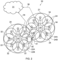
- FIG. 2 is a schematic diagram illustrating a network architecture for a new RAT wireless mobile telecommunications network / system 30 based on previously proposed approaches which may also be adapted to provide functionality in accordance with embodiments of the disclosure described herein.
- the new RAT network 30 represented in Figure 2 comprises a first communication cell 20 and a second communication cell 21.
- Each communication cell 20, 21, comprises a controlling node (centralised unit) 26, 28 in communication with a core network component 31 over a respective wired or wireless link 36, 38.
- the respective controlling nodes 26, 28 are also each in communication with a plurality of distributed units (radio access nodes / remote transmission and reception points (TRPs)) 22, 24 in their respective cells. Again, these communications may be over respective wired or wireless links.
- TRPs remote transmission and reception points
- the distributed units 22, 24 are responsible for providing the radio access interface for terminal devices connected to the network.
- Each distributed unit 22, 24 has a coverage area (radio access footprint) 32, 34 which together define the coverage of the respective communication cells 20, 21.
- Each distributed unit 22, 24 includes transceiver circuitry 22a, 24a for transmission and reception of wireless signals and processor circuitry 22b, 24b configured to control the respective distributed units 22, 24.
- the core network component 31 of the new RAT telecommunications system represented in Figure 2 may be broadly considered to correspond with the core network 12 represented in Figure 1 , and the respective controlling nodes 26, 28 and their associated distributed units / TRPs 22, 24 may be broadly considered to provide functionality corresponding to base stations of Figure 1 .
- the term network infrastructure equipment / access node may be used to encompass these elements and more conventional base station type elements of wireless telecommunications systems.
- the responsibility for scheduling transmissions which are scheduled on the radio interface between the respective distributed units and the terminal devices may lie with the controlling node / centralised unit and / or the distributed units / TRPs.
- a terminal device 40 is represented in Figure 2 within the coverage area of the first communication cell 20. This terminal device 40 may thus exchange signalling with the first controlling node 26 in the first communication cell via one of the distributed units 22 associated with the first communication cell 20. In some cases communications for a given terminal device are routed through only one of the distributed units, but it will be appreciated in some other implementations communications associated with a given terminal device may be routed through more than one distributed unit, for example in a soft handover scenario and other scenarios.
- the particular distributed unit(s) through which a terminal device is currently connected through to the associated controlling node may be referred to as active distributed units for the terminal device.
- the active subset of distributed units for a terminal device may comprise one or more than one distributed unit (TRP).
- the controlling node 26 is responsible for determining which of the distributed units 22 spanning the first communication cell 20 is responsible for radio communications with the terminal device 40 at any given time (i.e. which of the distributed units are currently active distributed units for the terminal device). Typically this will be based on measurements of radio channel conditions between the terminal device 40 and respective ones of the distributed units 22. In this regard, it will be appreciated the subset of the distributed units in a cell which are currently active for a terminal device will depend, at least in part, on the location of the terminal device within the cell (since this contributes significantly to the radio channel conditions that exist between the terminal device and respective ones of the distributed units).
- the involvement of the distributed units in routing communications from the terminal device to a controlling node is transparent to the terminal device 40. That is to say, in some cases the terminal device may not be aware of which distributed unit is responsible for routing communications between the terminal device 40 and the controlling node 26 of the communication cell 20 in which the terminal device is currently operating. In such cases, as far as the terminal device is concerned, it simply transmits uplink data to the controlling node 26 and receives downlink data from the controlling node 26 and the terminal device has no awareness of the involvement of the distributed units 22. However, in other embodiments, a terminal device may be aware of which distributed unit(s) are involved in its communications. Switching and scheduling of the one or more distributed units may be done at the network controlling node based on measurements by the distributed units of the terminal device uplink signal or measurements taken by the terminal device and reported to the controlling node via one or more distributed units.
- two communication cells 20, 21 and one terminal device 40 are shown for simplicity, but it will of course be appreciated that in practice the system may comprise a larger number of communication cells (each supported by a respective controlling node and plurality of distributed units) serving a larger number of terminal devices.
- Figure 2 represents merely one example of a proposed architecture for a new RAT telecommunications system in which approaches in accordance with the principles described herein may be adopted, and the functionality disclosed herein may also be applied in respect of wireless telecommunications systems having different architectures.
- the network infrastructure equipment / access node may comprise a base station, such as an LTE-type base station 11 as shown in Figure 1 which is adapted to provide functionality in accordance with the principles described herein, and in other examples the network infrastructure equipment may comprise a control unit / controlling node 26, 28 and / or a TRP 22, 24 of the kind shown in Figure 2 which is adapted to provide functionality in accordance with the principles described herein.
- a base station such as an LTE-type base station 11 as shown in Figure 1 which is adapted to provide functionality in accordance with the principles described herein
- the network infrastructure equipment may comprise a control unit / controlling node 26, 28 and / or a TRP 22, 24 of the kind shown in Figure 2 which is adapted to provide functionality in accordance with the principles described herein.
- RRC Radio Resource Control
- RRC_IDLE RRC idle mode
- RRC_CONNECTED RRC connected mode
- ECM-REGISTERED ECM-REGISTERED
- ECM-IDLE active communication
- RRC idle mode a terminal device is not connected to a radio network access node in the sense of not being able to communicate user plane data using the radio network access node.
- the terminal device may still receive some communications from base stations, for example reference signalling for cell reselection purposes and other broadcast signalling.
- the RRC connection setup procedure of going from RRC idle mode to RRC connected mode may be referred to as connecting to a cell / base station.
- the core network For a terminal device in RRC idle mode the core network is aware that the terminal device is present within the network, but the radio access network (RAN) part (comprising radio network infrastructure equipment such as the base stations 11 of Figure 1 and / or the combined TRPs / CUs of Figure 2 ) is not.
- the core network is aware of the location of idle mode terminal devices at a paging tracking area level but not at the level of individual transceiver entities.
- the core network will generally assume a terminal device is located within the tracking area(s) associated with a transceiver entity most recently used for communicating with the terminal device, unless the terminal device has since provided a specific tracking area update (TAU) to the network.
- TAU tracking area update
- idle mode terminal devices are typically required to send a TAU when they detect they have entered a different tracking area to allow the core network to keep track of their location.
- the core network tracks terminal devices at a tracking area level, it is generally not possible for the network infrastructure to know which specific transceiver entities (radio network node) to use when seeking to initiate contact with a terminal device in idle mode. Consequently, and as is well known, when a core network is required to connect to an idle mode terminal device a paging procedure is used.
- idle mode terminal devices are configured to monitor for paging messages periodically. For terminal devices operating in a discontinuous reception (DRX) mode this occurs when they wake up for their DRX awake time.
- Paging signals for a specific terminal device are transmitted in defined frames (Paging Frames) / sub-frames (Paging Occasions) which for a given terminal device may be derived from the International Mobile Subscriber Identifier (IMSI) of the terminal device, as well as paging related DRX parameters established in system information transmitted within the network.
- IMSI International Mobile Subscriber Identifier
- NR New Radio Access Technology
- WI Work Item
- the new RAT is expected to operate in a large range of frequencies, from hundreds of MHz to 100 GHz and it is expected to cover a broad range of use cases.
- a slot consists of multiple OFDM symbols, e.g. 14 symbols where a transmission of a physical channel can occur over one or more slots.
- the symbols within a slot can also be configured to operate in the uplink (UL) or downlink (DL) direction.
- the slot structure can be configured using 3 different methods, i.e.:
- the Slot Format Indicator (SFI) carries information relating to the structure of one or multiple slots and is carried by a Group Common PDCCH, where the SFI is transmitted to a group of UEs configured to monitor this Group Common PDCCH.
- One of the components of the slot structure information carried by the SFI is the DL & UL symbol configuration in a slot (or multiple slots). That is an indication of which symbols in a slot or multiple slots are for downlink or uplink transmissions.
- An example is shown in Figure 3 , where the Group Common PDCCH carrying the SFI is transmitted in the first 2 symbols of the slot and it indicates that the 3 rd till the 11 th symbols are used for downlink transmission and the 13 th and 14 th symbols are for uplink transmission.
- the 12 th is a gap between the downlink and uplink symbols for switching between DL and UL. This could be used for a PDSCH transmission in the DL (3 rd till 11 th symbols) followed by an acknowledgement in the uplink in the last two symbols.
- the symbol can also be configured as "Unknown” or “Reserved.”
- An “Unknown” symbol means that the symbol is flexible and can be overwritten by the UE specific DCI. That is a symbol can be configured as "Unknown” semi-statically or by the SFI and can be overwritten as a DL or an UL by the UE specific DCI.
- a “Reserved” symbol is not used and cannot be overwritten.
- the "Reserved” symbol is at least semi-statically configured (3GPP may decide later whether it can also be configured by the SFI).
- Embodiments of the present technique provide methods and apparatus which are operable to interpret symbols with conflicting configuration as flexible symbols. That is, such symbols can be overwritten by a dynamic configuration such as UE specific DCI to be either DL or UL.
- FIG. 5 shows a part schematic, part message flow diagram representation of a communications system 50 in accordance with embodiments of the present technique.
- the communications system 50 comprises an infrastructure equipment 51 of a wireless communications network and a communications device 52.
- Each of the infrastructure equipment 51 and communications device 52 comprise a transmitter (or transmitter circuitry) 51.1, 52.1, a receiver (or receiver circuitry) 51.2, 52.2 and a controller (or controller circuitry) 53.1, 53.2.
- Each of the controllers 53.1, 53.2 may be, for example, a microprocessor, a CPU, or a dedicated chipset, etc.
- the communications device 52 may not always include a transmitter 52.1, for example in scenarios where the communications device 52 is a low-power wearable device.
- the communications device 52 is configured to receive 54 from the infrastructure equipment 51 of the wireless communications network slot configuration information indicating a configuration of one or more slots of a wireless access interface provided by the wireless communications network for communicating data to the communications device 52 on a downlink and receiving data from the communications device 52 on an uplink, the time divided slots of the wireless access interface each providing a plurality of symbols on one of more radio frequency carrier signals which can be configured differently for use by the communications device 52 or the infrastructure equipment 51, the slot configuration information including an indication that one or more of the plurality of symbols are to be used for transmitting signals from the communications device 52 or that one or more of the plurality of symbols are to be used for receiving signals at the communications device 52, and in accordance with the received slot configuration information, to receive 56 signals by the communications device 52 in each of the one or more slots on the one or more of the symbols allocated from receiving signals, and to transmit 58 signals from the communications device in each of the one or more slots on the one or more of the symbols allocated to the communications device for transmitting signals.
- slot configuration information indicating a configuration
- the communications device 52 is configured to receive 541 first slot configuration information from the infrastructure equipment 51 indicating the configuration of a first plurality of the time slots, and to receive 542 subsequently at least one other slot configuration information from the infrastructure equipment 51 indicating the configuration of one or more of the first plurality of time slots, and if the at least one other slot configuration information indicates that one or more of the symbols of each of the one or more time slots are configured differently to the first slot configuration information, determining 544 a dynamic characteristic of the first slot information and the at least one other slot information, and determining 544 a configuration of the differently configured one or more symbols by the communications device 52 according to a conflict resolution rule based on the determined dynamic characteristic of the first slot configuration information and the determined dynamic characteristic of the at least one other slot configuration information.
- the dynamic characteristic may be for example one or both of a rate of change of the slot configuration information, or a persistence rate of the slot configuration information or a time duration over which the slot configuration information is valid.
- the determining the configuration of the differently configured one or more symbols by the communications device according to a conflict resolution rule comprises identifying the one or more symbols of each of the one or more time slots which are configured differently between the first slot configuration information and the at least one other slot configuration information, and if the dynamic characteristic is for example a rate of change of the first slot configuration information is less than the rate of change of the at least one other slot configuration information, determining the configuration of the one or more symbols according to the at least one other slot configuration information in preference to the first slot configuration information, else determining the configuration of the one or more symbols according to the first slot configuration information in preference to the at least one other slot configuration information.
- a more dynamic configuration method can overwrite a less dynamic configuration.
- the least dynamic configuration is the RRC configuration and the most dynamic configuration is the UE specific DCI.
- the SFI is more dynamic than that of the RRC configuration and less dynamic than that of the UE specific DCI.
- only conflicts between the RRC configuration and the SFI can be treated as flexible symbols. That is, any conflicting configuration between RRC and SFI would turn that symbol into an "Unknown" configuration, which can be overwritten by the UE specific DCI.
- An example is shown in Figure 6 , with symbols 4, 5, 6, 7 & 11 having conflicting configuration between RRC and SFI.
- these conflicts are resolved by turning these symbols as flexible or "Unknown" symbols. These symbols can therefore be overwritten by the most dynamic configuration, such as the UE specific DCI, that is, the DCI will indicate the final configuration for these symbols.
- symbol 8 in this example does not have any conflicts between the RRC and SFI configurations and hence should be regarded as DL but the DCI indicates that it is an UL, thereby causing ambiguity at the UE. It should be appreciated that although in this example UE specific DCI is used as the most dynamic configuration, other configurations more dynamic than those in RRC and SFI can also be used to overwrite conflicting symbol configurations.
- the at least one other slot configuration information comprises second slot configuration information indicating the configuration of a second duration comprising one or more time slots of the first plurality of time slots, and third slot configuration information indicating the configuration of a third duration comprising one or more time slots of the first plurality of time slots, and wherein the determining the configuration of the differently configured one or more symbols by the communications device according to a conflict resolution rule comprises identifying the one or more symbols of each of the one or more time slots which are configured differently between the first slot configuration information, the second slot configuration information and the third slot configuration information, identifying a shortest of the first duration, the second duration and third duration, and if the duration of the configuration of the plurality of time slots by the first slot configuration information is the shortest then determining the configuration of the one or more time slots which are configured differently according to the first slot configuration information, or if the duration of the configuration of the one or more of the time
- a “duration" of the of the slot configuration information means a length of time that the slot configuration information is valid, before the network or infrastructure equipment transmits new slot configuration information of the same method/format to supersede the old slot configuration information.
- the duration of RRC slot configuration information may persist and be valid until it is over-written by a further RRC configuration and so its duration may be measured in a number of hours, while the duration of DCI slot configuration information may change per slot and therefore has a much shorter duration.
- non-conflicting symbols between the RRC and SFI cannot be overwritten. That, is using the exemplary configurations shown in Figure 6 , symbol 8 shall be resolved as a DL symbol since the RRC and SFI indicates that it is a DL symbol, and per this embodiment it cannot be overwritten as shown in Figure 7 , even though the DCI indicates it as an UL symbol.
- conflicting symbols shall remain as flexible until they are overwritten by a DCI. That is, in the absence of a UE specific DCI configuration, these conflicting symbols shall remain as "Unknown” i. e. without direction and therefore they are not used by the UE.
- the determining the configuration of the differently configured one or more symbols by the communications device according to a conflict resolution rule comprises identifying the one or more symbols of each of the one or more time slots which are configured differently between the first slot configuration information and the at least one other slot configuration information, and if at least one of the first slot configuration information or the at least one other slot configuration information configures any of the one or more differently configured symbols as reserved, then determining that the configuration of the symbol is reserved.
- the UE-specific DCI indicates "Sidelink” symbols as the new slot format in the symbols 5 and 6, and Uplink symbol in the symbol 8.
- a sidelink capable UE assumes the symbols 5 and 6 as “Sidelink” symbols and the symbol 8 as "Reserved” symbol.
- the sidelink capable UE is new Release UE, and the sidelink can be a transmission direction for transmitting and/or receiving Device-to-Device (D2D) data to or from another capable UE.
- D2D Device-to-Device
- the determining the configuration of the differently configured one or more symbols by the communications device according to a conflict resolution rule comprises identifying the one or more symbols of each of the one or more time slots which are determined through the conflict resolution rule to be reserved, receiving a further slot configuration information from the infrastructure equipment indicating the configuration of one or more of the time slots, and, if the further configuration information indicates that one or more of the symbols of each of the one or more time slots are configured with a new slot format, determining based on the further slot configuration, for each symbol of each of the one or more time slots which are determined through the conflict resolution rule to be reserved, that the configuration of each symbol which is determined through the conflict resolution rule to be reserved is the new slot format.
- the new slot format indicates that the communications device should transmit signals or receive signals on a device-to-device, D2D, sidelink to another communications device, wherein the new slot format is only indicated in slot configuration information transmitted from the infrastructure equipment to D2D-enabled communications devices.
- the first slot configuration information and the at least one other slot configuration information are each provided by one of radio resource control information, a slot format indicator communicated in a group communications channel and a downlink control information, wherein the duration of a slot configuration information provided by radio resource control information is greater than a duration of a slot configuration information provided by a slot format indicator, and the duration of a slot configuration information is greater than a duration of a slot configuration information provided by a downlink control information.
- Figure 10 shows a first flow diagram illustrating a method of communications in a communications system in accordance with embodiments of the present technique.
- the flow diagram of Figure 10 corresponds to a portion of the part schematic, part message flow diagram representation of a communications system in accordance with embodiments of the present technique shown in Figure 5 .
- the method is a method of transmitting or receiving signals by a communications device communicating under control of a wireless communications network. The method starts in step S100.
- the method comprises in step S102, receiving from an infrastructure equipment of the wireless communications network slot configuration information indicating a configuration of one or more slots of a wireless access interface provided by the wireless communications network for communicating data to the communications device on a downlink and receiving data from the communications device on an uplink, the time divided slots of the wireless access interface each providing a plurality of symbols on one of more radio frequency carrier signals which can be configured differently for use by the communications device or the infrastructure equipment, the slot configuration information including an indication that one or more of the plurality of symbols are to be used for transmitting signals from the communications device or that one or more of the plurality of symbols are to be used for receiving signals at the communications device.
- step S104 the process comprises receiving signals by the communications device in each of the one or more slots on the one or more of the symbols allocated for receiving signals and in step S106, the method comprises transmitting signals from the communications device in each of the one or more slots on the one or more of the symbols allocated to the communications device for transmitting signals.
- step S108 the process comprises transmitting signals from the communications device in each of the one or more slots on the one or more of the symbols allocated to the communications device for transmitting signals.
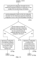
- FIG. 11 shows a second flow diagram illustrating a method of communications in a communications system in accordance with embodiments of the present technique.
- the flow diagram of Figure 11 corresponds to a portion of the part schematic, part message flow diagram representation of a communications system in accordance with embodiments of the present technique shown in Figure 5 , and furthermore takes place during step S102 of the method illustrated by the flow diagram of Figure 10 .
- the method starts in step S110.
- the method comprises in step S111, receiving first slot configuration information from the infrastructure equipment indicating the configuration of a first plurality of the time slots having a first duration.
- the process receiving subsequently at least one other slot configuration information from the infrastructure equipment indicating the configuration of one or more of the first plurality of time slots.
- step S114 the method comprises determining if the at least one other slot configuration information indicates that one or more of the symbols of each of the one or more time slots are configured differently to the first slot configuration information. Should the outcome of the determination of step S114 be "Yes” the method advances to step S116a, which comprises determining a configuration of the differently configured one or more symbols by the communications device according to a conflict resolution rule. However, if the outcome of the determination of step S114 be "No” the method advances to step S116b, which comprises determining a configuration of symbols by the communications device according to the first and the at least one other slot configuration information. The process ends in either step S118a or S118b.
- slot configuration information methods discussed in this document and in relation to embodiments of the present technique comprise RRC, SFI and DCI
- RRC, SFI and DCI slot configuration information methods
- those skilled in the art would appreciate that other configuration methods can also be used in embodiments of the present technique, or a subset of those discussed (RRC, SFI and DCI) may be used alone or in addition to other configuration methods not discussed herein.
- an infrastructure equipment or eNB can be configured to apply the same determination to configure any of the symbols which are differently configured by different slot configuration information. That is to say, although the eNB is transmitting the first and the subsequent slot configuration information which may conflict with respect to the configuration of one or more symbols in one of more of the same time slots as a result, for example, of a difference in short and long term requirement, the eNB can apply the same conflict resolution rule and the same calculation for the dynamic characteristic to that applied by the UE and so can make the same determination of the configuration of the differently configured or conflicting symbols as would be applied by the communications device.
- the infrastructure equipment may comprise transmitter circuitry configured to transmit signals to one or more wireless communications devices via a wireless access interface provided by the wireless communications network, receiver circuitry configured to receive signals from one or more of the communications devices transmitted via the wireless access interface, and controller circuitry for controlling the transmitter circuitry and the receiver circuitry to transmit the signals to the one or more communications devices and to receive signals from the one or more communications devices to communicate the data.
- the controller circuitry is configured with the transmitter circuitry and the receiver circuitry
- Described embodiments may be implemented in any suitable form including hardware, software, firmware or any combination of these. Described embodiments may optionally be implemented at least partly as computer software running on one or more data processors and/or digital signal processors.
- the elements and components of any embodiment may be physically, functionally and logically implemented in any suitable way. Indeed the functionality may be implemented in a single unit, in a plurality of units or as part of other functional units. As such, the disclosed embodiments may be implemented in a single unit or may be physically and functionally distributed between different units, circuitry and/or processors.
Landscapes
- Engineering & Computer Science (AREA)
- Signal Processing (AREA)
- Computer Networks & Wireless Communication (AREA)
- Mobile Radio Communication Systems (AREA)
Claims (15)
- Kommunikationsvorrichtung zum Senden oder Empfangen von Signalen zur Kommunikation von Daten unter der Steuerung eines drahtlosen Kommunikationsnetzwerks, wobei die Kommunikationsvorrichtung umfasst:Schaltlogik, die dazu konfiguriert ist, von der Infrastruktureinrichtung erste Zeitschlitz-Konfigurationsinformationen (S111) zu empfangen, die angeben, dass ein oder mehrere einer Vielzahl von Symbolen eines Zeitschlitzes zum Senden von Signalen von der Kommunikationsvorrichtung zu verwenden sind und dass eines oder mehrere der Vielzahl von Symbolen zum Empfangen von Signalen bei der Kommunikationsvorrichtung zu verwenden sind oder dass eines oder mehrere der Vielzahl von Symbolen flexible Symbole sind; undzweite Zeitschlitz-Konfigurationsinformationen zu empfangen, die eine Konfiguration eines oder mehrerer der Vielzahl von Symbolen des Zeitschlitzes (S112) angeben; undfalls die ersten Zeitschlitz-Konfigurationsinformationen angeben, dass eines oder mehrere der Vielzahl von Symbolen flexible Symbole sind, und die zweiten Zeitschlitz-Konfigurationsinformationen angeben, dass eines oder mehrere der Vielzahl von Symbolen des Zeitschlitzes anders als die ersten Zeitschlitz-Konfigurationsinformationen (S114) konfiguriert sind,zu bestimmen, dass eines oder mehrere der Vielzahl von Symbolen basierend auf den zweiten Zeitschlitz-Konfigurationsinformationen zu empfangen sind, wobei die zweiten Zeitschlitz-Konfigurationsinformationen eine dynamische Charakteristik einer höheren Änderungsrate der zweiten Zeitschlitz-Konfigurationsinformationen als eine der ersten Zeitschlitz-Konfigurationsinformationen aufweisen.
- Kommunikationsvorrichtung nach Anspruch 1, wobeidie ersten Zeitschlitz-Konfigurationsinformationen eine Konfiguration eines oder mehrerer Zeitschlitze einer drahtlosen Zugangsschnittstelle angeben, unddie Schaltlogik ferner dazu konfiguriert ist, die Signale in jedem Schlitz des einen oder der mehreren Zeitschlitze auf dem einen oder den mehreren der Vielzahl von Symbolen zu senden, die der Kommunikationsvorrichtung zum Senden von Signalen zugewiesen sind.
- Kommunikationsvorrichtung nach Anspruch 1, wobei eines oder mehrere der Vielzahl von Symbolen des in den zweiten Zeitschlitz-Konfigurationsinformationen angegebenen Zeitschlitzes auf einer Konfliktlösungsregel basieren, wobei die Konfliktlösungsregel einer dynamischen Charakteristik der ersten Zeitschlitz-Konfigurationsinformationen und dem dynamischen Charakteristik der zweiten Zeitschlitz-Konfigurationsinformationen entspricht.
- Kommunikationsvorrichtung nach Anspruch 1, wobei die Schaltlogik ferner dazu konfiguriert ist, das eine oder die mehreren aus der Vielzahl von Symbolen des Zeitschlitzes zu identifizieren, die in den ersten Zeitschlitz-Konfigurationsinformationen und den zweiten Zeitschlitz-Konfigurationsinformationen unterschiedlich konfiguriert sind, und eine Konfiguration des einen oder der mehreren aus der Vielzahl von Symbolen, die den zweiten Slot-Konfigurationsinformationen entspricht, bevorzugt gegenüber den ersten Slot-Konfigurationsinformationen zu bestimmen.
- Kommunikationsvorrichtung nach Anspruch 1, wobei die Schaltlogik ferner dazu konfiguriert ist, zu identifizieren, ob eines von den unterschiedlich konfigurierten einem oder den mehreren der Vielzahl von Symbolen in den ersten Zeitschlitz-Konfigurationsinformationen und den zweiten Zeitschlitz-Konfigurationsinformationen als reserviert konfiguriert sind, und falls mindestens eine von der der ersten Zeitschlitz-Konfigurationsinformationen und der zweiten Zeitschlitz-Konfigurationsinformationen eines von dem einen oder den mehreren unterschiedlich konfigurierten Symbole als reserviert konfiguriert, zu bestimmen, dass die Konfiguration des Symbols reserviert ist.
- Kommunikationsvorrichtung nach Anspruch 5, wobei die Schaltlogik weiterhin dazu konfiguriert ist, dritte Zeitschlitz-Konfigurationsinformationen von der Infrastruktureinrichtung zu empfangen, die eine Konfiguration eines oder mehrerer Zeitschlitzen angeben, und falls die dritten Zeitschlitz-Konfigurationsinformationen angeben, dass eines oder mehrere der Vielzahl von Symbolen eines jeden von dem einen oder den mehreren Zeitschlitzen mit einem neuen Zeitschlitz-Format konfiguriert sind, basierend auf den dritten Zeitschlitz-Konfigurationsinformationen zu bestimmen, dass eines oder mehrere der unterschiedlich konfigurierten Symbole entsprechend dem neuen Zeitschlitz-Format konfiguriert werden sollten.
- Kommunikationsvorrichtung nach Anspruch 6, wobei das neue Zeitschlitz-Format angibt, dass die Kommunikationsvorrichtung Signale über einen Gerät-Zu-Gerät-Sidelink (D2D-Sidelink) an eine andere Kommunikationsvorrichtung senden oder von ihr empfangen sollte, und das neue Zeitschlitz-Format nur in Zeitschlitz-Konfigurationsinformationen angegeben ist, die von der Infrastruktureinrichtung an D2D-fähige Kommunikationsvorrichtungen gesendet werden.
- Kommunikationsvorrichtung nach Anspruch 1, wobei die ersten Zeitschlitz-Konfigurationsinformationen und die zweiten Zeitschlitz-Konfigurationsinformationen jeweils durch eines von Funkressourcen-Steuerungsinformationen, einem in einem Gruppenkommunikationskanal übermittelten Zeitschlitz-Formatindikator und Downlink-Steuerungsinformationen bereitgestellt werden.
- Kommunikationsvorrichtung nach Anspruch 3, wobei die ersten Zeitschlitz-Konfigurationsinformationen und die zweiten Zeitschlitz-Konfigurationsinformationen jeweils durch eines von Funkressourcen-Steuerungsinformationen, einem in einem Gruppenkommunikationskanal übermittelten Zeitschlitz-Formatindikator und Downlink-Steuerungsinformationen bereitgestellt werden und die Änderungsrate der durch die Funkressourcen-Steuerungsinformationen bereitgestellten Zeitschlitz-Konfigurationsinformationen langsamer ist als die Änderungsrate der durch einen Zeitschlitz-Formatindikator bereitgestellten Zeitschlitz-Konfigurationsinformationen und die Änderungsrate der Zeitschlitz-Konfigurationsinformationen größer ist als die Änderungsrate der durch die Downlink-Steuerungsinformationen bereitgestellten Zeitschlitz-Konfigurationsinformationen.
- Kommunikationsvorrichtung nach Anspruch 9, wobei die Schaltlogik ferner dazu konfiguriert ist, zu bestimmen, dass eine Konfiguration von Symbolen, die durch jedes von den Funkressourcen-Steuerungsinformationen und dem Zeitschlitz-Formatindikator gleich konfiguriert werden und die durch die Downlink-Steuerungsinformationen unterschiedlich konfiguriert werden, dieselbe wie eine Konfiguration der Symbole durch die Funkressourcen-Steuerungsinformationen und den Zeitschlitz-Formatindikator sein sollte.
- Kommunikationsvorrichtung nach Anspruch 10, wobei die Schaltlogik bestimmt, dass die Konfiguration der Symbole, die durch die Funkressourcen-Steuerungsinformationen und den Zeitschlitz-Formatindikator unterschiedlich konfiguriert werden, eine flexible Konfiguration sein sollte.
- Kommunikationsvorrichtung nach Anspruch 11, wobei die Schaltlogik bestimmt, dass die Konfiguration der Symbole, die eine flexible Konfiguration aufweisen, dieselbe wie die Konfiguration der Symbole durch die Downlink-Steuerungsinformationen sein sollte.
- Kommunikationsvorrichtung nach Anspruch 10, wobei die Schaltlogik ferner dazu konfiguriert ist, zu bestimmen, falls mindestens eines von den Funkressourcen-Steuerungsinformationen und dem Zeitschlitz-Formatindikator eines des einen oder der mehreren unterschiedlich konfigurierten Symbole als reserviert konfiguriert, dass die Konfiguration des Symbols reserviert ist.
- Verfahren zum Senden oder Empfangen von Signalen durch eine Kommunikationsvorrichtung, die Daten unter der Steuerung eines drahtlosen Kommunikationsnetzwerks kommuniziert, wobei das Verfahren umfasst:Empfangen erster Zeitschlitz-Konfigurationsinformationen von einer Infrastruktureinrichtung, die angeben, dass eines oder mehrere einer Vielzahl von Symbolen eines Zeitschlitzes zum Senden von Signalen von der Kommunikationsvorrichtung verwendet werden sollen und dass eines oder mehrere der Vielzahl von Symbolen zum Empfangen von Signalen bei der Kommunikationsvorrichtung verwendet werden sollen oder dass eines oder mehrere der Vielzahl von Symbolen flexible Symbole sind;Empfangen zweiter Zeitschlitz-Konfigurationsinformationen, die eine Konfiguration eines oder mehrerer der Vielzahl von Symbolen des Zeitschlitzes angeben; und falls die ersten Zeitschlitz-Konfigurationsinformationen angeben, dass eines oder mehrere der Vielzahl von Symbolen flexible Symbole sind, und die zweiten Zeitschlitz-Konfigurationsinformationen angeben, dass eines oder mehrere der Symbole des Zeitschlitzes anders als die ersten Zeitschlitz-Konfigurationsinformationen konfiguriert sind, Bestimmen, dass eines oder mehrere der Symbole basierend auf den zweiten Zeitschlitz-Konfigurationsinformationen zu empfangen sind, wobei die zweiten Zeitschlitz-Konfigurationsinformationen eine dynamische Charakteristik einer höheren Änderungsrate der zweiten Zeitschlitz-Konfigurationsinformationen als eine der ersten Zeitschlitz-Konfigurationsinformationen aufweisen.
- Verfahren nach Anspruch 14, wobei die ersten Zeitschlitz-Konfigurationsinformationen eine Konfiguration eines oder mehrerer Zeitschlitze einer drahtlosen Zugangsschnittstelle angeben und das Verfahren ferner das Senden der Signale in jedem Zeitschlitz des einen oder der mehreren Zeitschlitze auf dem einen oder den mehreren der Vielzahl von Symbolen umfasst, die der Kommunikationsvorrichtung zum Senden von Signalen zugewiesen sind.
Priority Applications (1)
| Application Number | Priority Date | Filing Date | Title |
|---|---|---|---|
| EP24176433.1A EP4401494B1 (de) | 2017-09-29 | 2018-08-15 | Verfahren, infrastrukturausrüstung und kommunikationsvorrichtung |
Applications Claiming Priority (3)
| Application Number | Priority Date | Filing Date | Title |
|---|---|---|---|
| EP17194261 | 2017-09-29 | ||
| PCT/EP2018/072137 WO2019063188A1 (en) | 2017-09-29 | 2018-08-15 | METHODS, INFRASTRUCTURE EQUIPMENT AND COMMUNICATION DEVICE |
| EP18752168.7A EP3673692B1 (de) | 2017-09-29 | 2018-08-15 | Verfahren, infrastrukturausrüstung und kommunikationsvorrichtung |
Related Parent Applications (1)
| Application Number | Title | Priority Date | Filing Date |
|---|---|---|---|
| EP18752168.7A Division EP3673692B1 (de) | 2017-09-29 | 2018-08-15 | Verfahren, infrastrukturausrüstung und kommunikationsvorrichtung |
Related Child Applications (2)
| Application Number | Title | Priority Date | Filing Date |
|---|---|---|---|
| EP24176433.1A Division EP4401494B1 (de) | 2017-09-29 | 2018-08-15 | Verfahren, infrastrukturausrüstung und kommunikationsvorrichtung |
| EP24176433.1A Division-Into EP4401494B1 (de) | 2017-09-29 | 2018-08-15 | Verfahren, infrastrukturausrüstung und kommunikationsvorrichtung |
Publications (3)
| Publication Number | Publication Date |
|---|---|
| EP4236550A2 EP4236550A2 (de) | 2023-08-30 |
| EP4236550A3 EP4236550A3 (de) | 2023-10-11 |
| EP4236550B1 true EP4236550B1 (de) | 2025-02-12 |
Family
ID=60001757
Family Applications (3)
| Application Number | Title | Priority Date | Filing Date |
|---|---|---|---|
| EP23178306.9A Active EP4236550B1 (de) | 2017-09-29 | 2018-08-15 | Verfahren, infrastrukturausrüstung und kommunikationsvorrichtung |
| EP18752168.7A Active EP3673692B1 (de) | 2017-09-29 | 2018-08-15 | Verfahren, infrastrukturausrüstung und kommunikationsvorrichtung |
| EP24176433.1A Active EP4401494B1 (de) | 2017-09-29 | 2018-08-15 | Verfahren, infrastrukturausrüstung und kommunikationsvorrichtung |
Family Applications After (2)
| Application Number | Title | Priority Date | Filing Date |
|---|---|---|---|
| EP18752168.7A Active EP3673692B1 (de) | 2017-09-29 | 2018-08-15 | Verfahren, infrastrukturausrüstung und kommunikationsvorrichtung |
| EP24176433.1A Active EP4401494B1 (de) | 2017-09-29 | 2018-08-15 | Verfahren, infrastrukturausrüstung und kommunikationsvorrichtung |
Country Status (3)
| Country | Link |
|---|---|
| US (3) | US11419102B2 (de) |
| EP (3) | EP4236550B1 (de) |
| WO (1) | WO2019063188A1 (de) |
Families Citing this family (6)
| Publication number | Priority date | Publication date | Assignee | Title |
|---|---|---|---|---|
| CN111165036A (zh) * | 2017-12-26 | 2020-05-15 | Oppo广东移动通信有限公司 | 一种数据传输方法及装置、计算机存储介质 |
| EP3833129B1 (de) * | 2018-09-07 | 2023-11-01 | Guangdong Oppo Mobile Telecommunications Corp., Ltd. | Verfahren zur übertragung von konfigurationsinformationen und endgerätevorrichtung |
| US11115972B2 (en) * | 2018-11-02 | 2021-09-07 | Qualcomm Incorporated | Techniques for updating resource types |
| US11632223B2 (en) * | 2019-12-27 | 2023-04-18 | Qualcomm Incorporated | Slot format configuration to support full-duplex operation |
| US12457141B2 (en) * | 2020-05-14 | 2025-10-28 | Ntt Docomo, Inc. | Terminal |
| US12501420B2 (en) * | 2022-09-23 | 2025-12-16 | Qualcomm Incorporated | Signaling to override radio resource control (RRC) configured direction |
Family Cites Families (18)
| Publication number | Priority date | Publication date | Assignee | Title |
|---|---|---|---|---|
| US20070237254A1 (en) * | 2006-04-10 | 2007-10-11 | Nokia Corporation | Configuring a device for wireless communication |
| EP2245879A1 (de) * | 2008-01-30 | 2010-11-03 | Telefonaktiebolaget LM Ericsson (publ) | Konfigurationsmessungszeitschlitze für mobile endgeräte in einem tdd-system |
| WO2011086920A1 (ja) * | 2010-01-14 | 2011-07-21 | パナソニック株式会社 | 無線通信端末装置、無線通信基地局装置及び無線通信方法 |
| US8867458B2 (en) * | 2010-04-30 | 2014-10-21 | Nokia Corporation | Network controlled device to device / machine to machine cluster operation |
| US9450766B2 (en) * | 2011-04-26 | 2016-09-20 | Openet Telecom Ltd. | Systems, devices and methods of distributing telecommunications functionality across multiple heterogeneous domains |
| US8958807B2 (en) * | 2012-01-09 | 2015-02-17 | Samsung Electronic Co., Ltd. | Method and apparatus for providing communication service to mobile station by multiple base stations in cooperation in wireless communication system |
| US9374189B2 (en) * | 2012-12-21 | 2016-06-21 | Blackberry Limited | Method and apparatus for interference mitigation in time division duplex systems |
| US10299284B2 (en) | 2015-08-31 | 2019-05-21 | Qualcomm, Incorporated | Inter-access terminal unblocking and enhanced contention for co-existence on a shared communication medium |
| US10205581B2 (en) * | 2016-09-22 | 2019-02-12 | Huawei Technologies Co., Ltd. | Flexible slot architecture for low latency communication |
| KR102164967B1 (ko) * | 2017-01-06 | 2020-10-13 | 한국전자통신연구원 | 통신 시스템에서 제어 채널의 송수신 방법 및 장치 |
| US11483810B2 (en) * | 2017-04-03 | 2022-10-25 | Huawei Technologies Co., Ltd. | Methods and systems for resource configuration of wireless communication systems |
| CN108811120B (zh) * | 2017-05-05 | 2023-05-02 | 中兴通讯股份有限公司 | 数据传输方法及装置 |
| KR20190129126A (ko) * | 2017-05-05 | 2019-11-19 | 텔레호낙티에볼라게트 엘엠 에릭슨(피유비엘) | 무선 통신을 위한 뉴머롤로지-종속적 물리적 업링크 제어 채널 구조 |
| CN109152024B (zh) * | 2017-06-16 | 2023-06-23 | 华为技术有限公司 | 一种指示方法、处理方法及装置 |
| CN115642994B (zh) * | 2017-08-11 | 2025-04-25 | 韦勒斯标准与技术协会公司 | 发送或接收上行链路控制信道的方法、设备和系统 |
| CN110999190B (zh) * | 2017-08-14 | 2023-08-18 | 韩国电子通信研究院 | 用于在通信系统中传送和接收时隙设定信息的方法 |
| US10736099B2 (en) * | 2017-08-18 | 2020-08-04 | Qualcomm Incorporated | Resolving slot format conflicts for wireless systems |
| EP4492716A3 (de) * | 2017-09-11 | 2025-04-23 | Wilus Institute of Standards and Technology Inc. | Verfahren, vorrichtung und system für uplink-übertragung und downlink-empfang in einem drahtlosen kommunikationssystem |
-
2018
- 2018-08-15 EP EP23178306.9A patent/EP4236550B1/de active Active
- 2018-08-15 EP EP18752168.7A patent/EP3673692B1/de active Active
- 2018-08-15 EP EP24176433.1A patent/EP4401494B1/de active Active
- 2018-08-15 WO PCT/EP2018/072137 patent/WO2019063188A1/en not_active Ceased
- 2018-08-15 US US16/646,149 patent/US11419102B2/en active Active
-
2022
- 2022-07-26 US US17/873,183 patent/US12058695B2/en active Active
-
2024
- 2024-04-26 US US18/646,829 patent/US20240276512A1/en active Pending
Also Published As
| Publication number | Publication date |
|---|---|
| US20220386286A1 (en) | 2022-12-01 |
| EP3673692B1 (de) | 2023-07-12 |
| EP4236550A3 (de) | 2023-10-11 |
| US12058695B2 (en) | 2024-08-06 |
| EP4401494A3 (de) | 2024-08-07 |
| US20240276512A1 (en) | 2024-08-15 |
| EP4236550A2 (de) | 2023-08-30 |
| US20200275418A1 (en) | 2020-08-27 |
| EP4401494B1 (de) | 2025-10-08 |
| EP4401494A2 (de) | 2024-07-17 |
| US11419102B2 (en) | 2022-08-16 |
| EP4401494C0 (de) | 2025-10-08 |
| EP3673692A1 (de) | 2020-07-01 |
| WO2019063188A1 (en) | 2019-04-04 |
Similar Documents
| Publication | Publication Date | Title |
|---|---|---|
| US12058695B2 (en) | Methods, infrastructure equipment and communications device | |
| WO2018230603A1 (en) | Uplink carrier selection for prach transmission between a nr dedicated carrier and a lte/nr shared carrier | |
| US12119923B2 (en) | Methods and infrastructure equipment | |
| KR20130001096A (ko) | 무선 통신 시스템에서 랜덤 액세스의 수행장치 및 방법 | |
| WO2017122752A1 (ja) | ユーザ端末、無線基地局及び無線通信方法 | |
| CN110583044A (zh) | 移动通信网络、通信装置、基础设施设备和方法 | |
| US10681623B2 (en) | Methods and apparatus for cell access via anchor carrier | |
| US20250168794A1 (en) | Methods, infrastructure equipment and communications device | |
| US20220303931A1 (en) | Infrastructure equipment, wireless communications system, communications device and methods | |
| WO2017195479A1 (ja) | 端末装置、基地局装置、通信方法 | |
| CA3203327A1 (en) | Method and apparatus for configured grant based transmission | |
| EP4371258B1 (de) | Verfahren, kommunikationsvorrichtungen und infrastrukturausrüstung | |
| CN118901260A (zh) | 方法、通信装置和基础设施设备 | |
| JP2024518669A (ja) | Sdtを用いるオンデマンドsibの配信 | |
| US20240267873A1 (en) | Positioning measurement with low latency | |
| CN121079936A (zh) | 侧链路和双侧往返时间定位 | |
| KR20240131803A (ko) | 차세대 무선 이동통신에서 사이드링크 기반 포지셔닝을 위한 후보 앵커 단말 탐색 방법 및 장치 |
Legal Events
| Date | Code | Title | Description |
|---|---|---|---|
| PUAI | Public reference made under article 153(3) epc to a published international application that has entered the european phase |
Free format text: ORIGINAL CODE: 0009012 |
|
| STAA | Information on the status of an ep patent application or granted ep patent |
Free format text: STATUS: REQUEST FOR EXAMINATION WAS MADE |
|
| 17P | Request for examination filed |
Effective date: 20230621 |
|
| AC | Divisional application: reference to earlier application |
Ref document number: 3673692 Country of ref document: EP Kind code of ref document: P |
|
| AK | Designated contracting states |
Kind code of ref document: A2 Designated state(s): AL AT BE BG CH CY CZ DE DK EE ES FI FR GB GR HR HU IE IS IT LI LT LU LV MC MK MT NL NO PL PT RO RS SE SI SK SM TR |
|
| REG | Reference to a national code |
Ref country code: DE Free format text: PREVIOUS MAIN CLASS: H04W0072044600 Ref country code: DE Ref legal event code: R079 Ref document number: 602018079245 Country of ref document: DE Free format text: PREVIOUS MAIN CLASS: H04W0072044600 Ipc: H04W0072230000 |
|
| PUAL | Search report despatched |
Free format text: ORIGINAL CODE: 0009013 |
|
| AK | Designated contracting states |
Kind code of ref document: A3 Designated state(s): AL AT BE BG CH CY CZ DE DK EE ES FI FR GB GR HR HU IE IS IT LI LT LU LV MC MK MT NL NO PL PT RO RS SE SI SK SM TR |
|
| RIC1 | Information provided on ipc code assigned before grant |
Ipc: H04W 72/0446 20230101ALN20230904BHEP Ipc: H04W 72/23 20230101AFI20230904BHEP |
|
| GRAP | Despatch of communication of intention to grant a patent |
Free format text: ORIGINAL CODE: EPIDOSNIGR1 |
|
| STAA | Information on the status of an ep patent application or granted ep patent |
Free format text: STATUS: GRANT OF PATENT IS INTENDED |
|
| RIC1 | Information provided on ipc code assigned before grant |
Ipc: H04L 5/14 20060101ALN20240827BHEP Ipc: H04W 72/0446 20230101ALN20240827BHEP Ipc: H04L 5/00 20060101ALI20240827BHEP Ipc: H04W 72/23 20230101AFI20240827BHEP |
|
| INTG | Intention to grant announced |
Effective date: 20240910 |
|
| RIC1 | Information provided on ipc code assigned before grant |
Ipc: H04L 5/14 20060101ALN20240903BHEP Ipc: H04W 72/0446 20230101ALN20240903BHEP Ipc: H04L 5/00 20060101ALI20240903BHEP Ipc: H04W 72/23 20230101AFI20240903BHEP |
|
| GRAS | Grant fee paid |
Free format text: ORIGINAL CODE: EPIDOSNIGR3 |
|
| GRAA | (expected) grant |
Free format text: ORIGINAL CODE: 0009210 |
|
| STAA | Information on the status of an ep patent application or granted ep patent |
Free format text: STATUS: THE PATENT HAS BEEN GRANTED |
|
| P01 | Opt-out of the competence of the unified patent court (upc) registered |
Free format text: CASE NUMBER: APP_66837/2024 Effective date: 20241217 |
|
| AC | Divisional application: reference to earlier application |
Ref document number: 3673692 Country of ref document: EP Kind code of ref document: P |
|
| AK | Designated contracting states |
Kind code of ref document: B1 Designated state(s): AL AT BE BG CH CY CZ DE DK EE ES FI FR GB GR HR HU IE IS IT LI LT LU LV MC MK MT NL NO PL PT RO RS SE SI SK SM TR |
|
| REG | Reference to a national code |
Ref country code: GB Ref legal event code: FG4D |
|
| REG | Reference to a national code |
Ref country code: CH Ref legal event code: EP |
|
| REG | Reference to a national code |
Ref country code: DE Ref legal event code: R096 Ref document number: 602018079245 Country of ref document: DE |
|
| REG | Reference to a national code |
Ref country code: IE Ref legal event code: FG4D |
|
| REG | Reference to a national code |
Ref country code: NL Ref legal event code: FP |
|
| PG25 | Lapsed in a contracting state [announced via postgrant information from national office to epo] |
Ref country code: RS Free format text: LAPSE BECAUSE OF FAILURE TO SUBMIT A TRANSLATION OF THE DESCRIPTION OR TO PAY THE FEE WITHIN THE PRESCRIBED TIME-LIMIT Effective date: 20250512 |
|
| PG25 | Lapsed in a contracting state [announced via postgrant information from national office to epo] |
Ref country code: FI Free format text: LAPSE BECAUSE OF FAILURE TO SUBMIT A TRANSLATION OF THE DESCRIPTION OR TO PAY THE FEE WITHIN THE PRESCRIBED TIME-LIMIT Effective date: 20250212 |
|
| PG25 | Lapsed in a contracting state [announced via postgrant information from national office to epo] |
Ref country code: PL Free format text: LAPSE BECAUSE OF FAILURE TO SUBMIT A TRANSLATION OF THE DESCRIPTION OR TO PAY THE FEE WITHIN THE PRESCRIBED TIME-LIMIT Effective date: 20250212 |
|
| PG25 | Lapsed in a contracting state [announced via postgrant information from national office to epo] |
Ref country code: ES Free format text: LAPSE BECAUSE OF FAILURE TO SUBMIT A TRANSLATION OF THE DESCRIPTION OR TO PAY THE FEE WITHIN THE PRESCRIBED TIME-LIMIT Effective date: 20250212 |
|
| REG | Reference to a national code |
Ref country code: LT Ref legal event code: MG9D |
|
| PG25 | Lapsed in a contracting state [announced via postgrant information from national office to epo] |
Ref country code: IS Free format text: LAPSE BECAUSE OF FAILURE TO SUBMIT A TRANSLATION OF THE DESCRIPTION OR TO PAY THE FEE WITHIN THE PRESCRIBED TIME-LIMIT Effective date: 20250612 Ref country code: NO Free format text: LAPSE BECAUSE OF FAILURE TO SUBMIT A TRANSLATION OF THE DESCRIPTION OR TO PAY THE FEE WITHIN THE PRESCRIBED TIME-LIMIT Effective date: 20250512 |
|
| PG25 | Lapsed in a contracting state [announced via postgrant information from national office to epo] |
Ref country code: HR Free format text: LAPSE BECAUSE OF FAILURE TO SUBMIT A TRANSLATION OF THE DESCRIPTION OR TO PAY THE FEE WITHIN THE PRESCRIBED TIME-LIMIT Effective date: 20250212 |
|
| PG25 | Lapsed in a contracting state [announced via postgrant information from national office to epo] |
Ref country code: PT Free format text: LAPSE BECAUSE OF FAILURE TO SUBMIT A TRANSLATION OF THE DESCRIPTION OR TO PAY THE FEE WITHIN THE PRESCRIBED TIME-LIMIT Effective date: 20250612 Ref country code: LV Free format text: LAPSE BECAUSE OF FAILURE TO SUBMIT A TRANSLATION OF THE DESCRIPTION OR TO PAY THE FEE WITHIN THE PRESCRIBED TIME-LIMIT Effective date: 20250212 |
|
| PG25 | Lapsed in a contracting state [announced via postgrant information from national office to epo] |
Ref country code: GR Free format text: LAPSE BECAUSE OF FAILURE TO SUBMIT A TRANSLATION OF THE DESCRIPTION OR TO PAY THE FEE WITHIN THE PRESCRIBED TIME-LIMIT Effective date: 20250513 Ref country code: BG Free format text: LAPSE BECAUSE OF FAILURE TO SUBMIT A TRANSLATION OF THE DESCRIPTION OR TO PAY THE FEE WITHIN THE PRESCRIBED TIME-LIMIT Effective date: 20250212 |
|
| REG | Reference to a national code |
Ref country code: AT Ref legal event code: MK05 Ref document number: 1767307 Country of ref document: AT Kind code of ref document: T Effective date: 20250212 |
|
| PGFP | Annual fee paid to national office [announced via postgrant information from national office to epo] |
Ref country code: NL Payment date: 20250723 Year of fee payment: 8 |
|
| PG25 | Lapsed in a contracting state [announced via postgrant information from national office to epo] |
Ref country code: SE Free format text: LAPSE BECAUSE OF FAILURE TO SUBMIT A TRANSLATION OF THE DESCRIPTION OR TO PAY THE FEE WITHIN THE PRESCRIBED TIME-LIMIT Effective date: 20250212 |
|
| PG25 | Lapsed in a contracting state [announced via postgrant information from national office to epo] |
Ref country code: SM Free format text: LAPSE BECAUSE OF FAILURE TO SUBMIT A TRANSLATION OF THE DESCRIPTION OR TO PAY THE FEE WITHIN THE PRESCRIBED TIME-LIMIT Effective date: 20250212 |
|
| PG25 | Lapsed in a contracting state [announced via postgrant information from national office to epo] |
Ref country code: DK Free format text: LAPSE BECAUSE OF FAILURE TO SUBMIT A TRANSLATION OF THE DESCRIPTION OR TO PAY THE FEE WITHIN THE PRESCRIBED TIME-LIMIT Effective date: 20250212 |
|
| PGFP | Annual fee paid to national office [announced via postgrant information from national office to epo] |
Ref country code: DE Payment date: 20250724 Year of fee payment: 8 |
|
| PG25 | Lapsed in a contracting state [announced via postgrant information from national office to epo] |
Ref country code: IT Free format text: LAPSE BECAUSE OF FAILURE TO SUBMIT A TRANSLATION OF THE DESCRIPTION OR TO PAY THE FEE WITHIN THE PRESCRIBED TIME-LIMIT Effective date: 20250212 |
|
| PGFP | Annual fee paid to national office [announced via postgrant information from national office to epo] |
Ref country code: GB Payment date: 20250724 Year of fee payment: 8 |
|
| PG25 | Lapsed in a contracting state [announced via postgrant information from national office to epo] |
Ref country code: AT Free format text: LAPSE BECAUSE OF FAILURE TO SUBMIT A TRANSLATION OF THE DESCRIPTION OR TO PAY THE FEE WITHIN THE PRESCRIBED TIME-LIMIT Effective date: 20250212 |
|
| PGFP | Annual fee paid to national office [announced via postgrant information from national office to epo] |
Ref country code: FR Payment date: 20250725 Year of fee payment: 8 |
|
| PG25 | Lapsed in a contracting state [announced via postgrant information from national office to epo] |
Ref country code: EE Free format text: LAPSE BECAUSE OF FAILURE TO SUBMIT A TRANSLATION OF THE DESCRIPTION OR TO PAY THE FEE WITHIN THE PRESCRIBED TIME-LIMIT Effective date: 20250212 Ref country code: CZ Free format text: LAPSE BECAUSE OF FAILURE TO SUBMIT A TRANSLATION OF THE DESCRIPTION OR TO PAY THE FEE WITHIN THE PRESCRIBED TIME-LIMIT Effective date: 20250212 |
|
| PG25 | Lapsed in a contracting state [announced via postgrant information from national office to epo] |
Ref country code: RO Free format text: LAPSE BECAUSE OF FAILURE TO SUBMIT A TRANSLATION OF THE DESCRIPTION OR TO PAY THE FEE WITHIN THE PRESCRIBED TIME-LIMIT Effective date: 20250212 |
|
| PG25 | Lapsed in a contracting state [announced via postgrant information from national office to epo] |
Ref country code: SK Free format text: LAPSE BECAUSE OF FAILURE TO SUBMIT A TRANSLATION OF THE DESCRIPTION OR TO PAY THE FEE WITHIN THE PRESCRIBED TIME-LIMIT Effective date: 20250212 |