EP4236473B1 - Zellmessverfahren und zugehörige vorrichtung - Google Patents
Zellmessverfahren und zugehörige vorrichtung Download PDFInfo
- Publication number
- EP4236473B1 EP4236473B1 EP20963103.5A EP20963103A EP4236473B1 EP 4236473 B1 EP4236473 B1 EP 4236473B1 EP 20963103 A EP20963103 A EP 20963103A EP 4236473 B1 EP4236473 B1 EP 4236473B1
- Authority
- EP
- European Patent Office
- Prior art keywords
- cell
- serving cell
- terminal device
- access network
- network device
- Prior art date
- Legal status (The legal status is an assumption and is not a legal conclusion. Google has not performed a legal analysis and makes no representation as to the accuracy of the status listed.)
- Active
Links
Images


Classifications
-
- H—ELECTRICITY
- H04—ELECTRIC COMMUNICATION TECHNIQUE
- H04W—WIRELESS COMMUNICATION NETWORKS
- H04W36/00—Hand-off or reselection arrangements
- H04W36/08—Reselecting an access point
-
- H—ELECTRICITY
- H04—ELECTRIC COMMUNICATION TECHNIQUE
- H04L—TRANSMISSION OF DIGITAL INFORMATION, e.g. TELEGRAPHIC COMMUNICATION
- H04L5/00—Arrangements affording multiple use of the transmission path
- H04L5/003—Arrangements for allocating sub-channels of the transmission path
- H04L5/0048—Allocation of pilot signals, i.e. of signals known to the receiver
- H04L5/005—Allocation of pilot signals, i.e. of signals known to the receiver of common pilots, i.e. pilots destined for multiple users or terminals
-
- H—ELECTRICITY
- H04—ELECTRIC COMMUNICATION TECHNIQUE
- H04W—WIRELESS COMMUNICATION NETWORKS
- H04W24/00—Supervisory, monitoring or testing arrangements
- H04W24/08—Testing, supervising or monitoring using real traffic
-
- H—ELECTRICITY
- H04—ELECTRIC COMMUNICATION TECHNIQUE
- H04W—WIRELESS COMMUNICATION NETWORKS
- H04W36/00—Hand-off or reselection arrangements
- H04W36/0005—Control or signalling for completing the hand-off
- H04W36/0055—Transmission or use of information for re-establishing the radio link
- H04W36/0058—Transmission of hand-off measurement information, e.g. measurement reports
-
- H—ELECTRICITY
- H04—ELECTRIC COMMUNICATION TECHNIQUE
- H04W—WIRELESS COMMUNICATION NETWORKS
- H04W36/00—Hand-off or reselection arrangements
- H04W36/0005—Control or signalling for completing the hand-off
- H04W36/0083—Determination of parameters used for hand-off, e.g. generation or modification of neighbour cell lists
- H04W36/0085—Hand-off measurements
-
- H—ELECTRICITY
- H04—ELECTRIC COMMUNICATION TECHNIQUE
- H04W—WIRELESS COMMUNICATION NETWORKS
- H04W36/00—Hand-off or reselection arrangements
- H04W36/13—Cell handover without a predetermined boundary, e.g. virtual cells
-
- H—ELECTRICITY
- H04—ELECTRIC COMMUNICATION TECHNIQUE
- H04W—WIRELESS COMMUNICATION NETWORKS
- H04W36/00—Hand-off or reselection arrangements
- H04W36/14—Reselecting a network or an air interface
-
- H—ELECTRICITY
- H04—ELECTRIC COMMUNICATION TECHNIQUE
- H04W—WIRELESS COMMUNICATION NETWORKS
- H04W36/00—Hand-off or reselection arrangements
- H04W36/24—Reselection being triggered by specific parameters
- H04W36/30—Reselection being triggered by specific parameters by measured or perceived connection quality data
-
- Y—GENERAL TAGGING OF NEW TECHNOLOGICAL DEVELOPMENTS; GENERAL TAGGING OF CROSS-SECTIONAL TECHNOLOGIES SPANNING OVER SEVERAL SECTIONS OF THE IPC; TECHNICAL SUBJECTS COVERED BY FORMER USPC CROSS-REFERENCE ART COLLECTIONS [XRACs] AND DIGESTS
- Y02—TECHNOLOGIES OR APPLICATIONS FOR MITIGATION OR ADAPTATION AGAINST CLIMATE CHANGE
- Y02D—CLIMATE CHANGE MITIGATION TECHNOLOGIES IN INFORMATION AND COMMUNICATION TECHNOLOGIES [ICT], I.E. INFORMATION AND COMMUNICATION TECHNOLOGIES AIMING AT THE REDUCTION OF THEIR OWN ENERGY USE
- Y02D30/00—Reducing energy consumption in communication networks
- Y02D30/70—Reducing energy consumption in communication networks in wireless communication networks
Definitions
- This application relates to the field of mobile communication technologies, and in particular, to a cell measurement method and a related apparatus.
- New Radio New Radio
- LTE Long Term Evolution
- two neighboring cells may support different standards.
- intra-frequency measurement and handover in a same communication standard are performed to ensure that a mobile terminal can always be in a cell with a strongest signal in the same communication standard, and the terminal device cannot perform inter-standard intra-frequency measurement without additional power consumption.
- the neighboring cell signal sent by a neighboring inter-standard intra-frequency cell When a neighboring cell signal sent by a neighboring inter-standard intra-frequency cell is stronger than a service signal provided by a serving cell, the neighboring cell signal causes strong interference to the service signal received by the terminal device.
- the terminal device increases power of a transmit signal of the terminal device.
- the uplink signal sent by the terminal device interferes with an uplink signal sent by another terminal device in the serving cell.
- the foregoing case is referred to as near-far interference. How to avoid near-far interference to the terminal device in intra-frequency inter-standard networking is a problem to be urgently resolved by a person skilled in the art.
- This application provides a cell measurement method and a related apparatus, to avoid near-far interference to a terminal device.
- this application provides a cell measurement method.
- the method includes: A first access network device sends first measurement control information to a terminal device through a first serving cell.
- the first measurement control information indicates the terminal device to measure quality of a downlink reference signal of a virtual cell.
- a center frequency of a downlink reference signal of the first serving cell is the same as a center frequency of the downlink reference signal of the virtual cell, a frequency range of the virtual cell is included in a frequency range of a second serving cell, and the frequency range of the second serving cell overlaps with a frequency range of the first serving cell.
- the first access network device receives a first measurement report from the terminal device, where the first measurement report indicates the quality of the downlink reference signal of the virtual cell.
- the first access network device migrates the terminal device to a third serving cell when the quality of the downlink reference signal of the virtual cell is higher than quality of the downlink reference signal of the first serving cell.
- a standard of the second serving cell is different from a standard of the first serving cell, or a standard of the second serving cell is the same as a standard of the first serving cell and a center frequency of a downlink reference signal of the second serving cell is different from the center frequency of the downlink reference signal of the first serving cell.
- the virtual cell and the second serving cell are cells of the first access network device, or the virtual cell and the second serving cell are cells of a second access network device.
- a standard of the third serving cell is the same as the standard of the first serving cell, and a center frequency of a downlink reference signal of the third serving cell is different from the center frequency of the downlink reference signal of the first serving cell, or a standard of the third serving cell is different from the standard of the first serving cell.
- Near-far interference to the terminal device can be avoided by using the method.
- that the first access network device migrates the terminal device to a third serving cell includes: The first access network device sends second measurement control information to the terminal device, where the second measurement control information indicates the terminal device to measure quality of the downlink reference signal of the third serving cell. The first access network device receives a second measurement report from the terminal device, where the second measurement report indicates the quality of the downlink reference signal of the third serving cell. The first access network device migrates the terminal device to the third serving cell based on the second measurement report.
- the first access network device stores one or more cell identifiers of one or more serving cells neighboring to the first serving cell.
- the first access network device stores a cell identifier of the virtual cell, and a first measurement result includes the cell identifier of the virtual cell.
- the first access network device stores the cell identifiers of the one or more serving cells neighboring to the first serving cell, a first measurement result includes a cell identifier of the virtual cell, and the cell identifier of the virtual cell is different from the cell identifiers of the one or more serving cells.
- the virtual cell does not provide an access service for the terminal device.
- the standard supported by the first serving cell is a long term evolution LTE standard, and the standard supported by the second serving cell is a new radio NR standard; or the standard supported by the first serving cell is an NR standard, and the standard supported by the second serving cell is an LTE standard.
- the virtual cell and the second serving cell are the cells of the first access network device, and the method further includes: The first access network device sends a downlink signal of the virtual cell, where the downlink signal includes the downlink reference signal of the virtual cell.
- the downlink reference signal includes a cell-specific reference signal CRS.
- the downlink signal further includes one or more of a primary synchronization signal PSS, a secondary synchronization signal SSS, and a system information block
- the system information block includes indication information indicating that the virtual cell does not provide an access service for the terminal device.
- the downlink reference signal is a demodulation reference signal DMRS
- the downlink signal is a synchronization signal and physical broadcast channel block SSB
- the SSB includes the DMRS.
- the method further includes: The first access network device sends, through the second serving cell, indication information to a terminal device accessing the second serving cell.
- the indication information indicates an available time-frequency resource of the terminal device accessing the second serving cell, and the available time-frequency resource is different from a time-frequency resource occupied by the downlink signal of the virtual cell or indicates that the terminal device accessing the second serving cell does not use a time-frequency resource occupied by the downlink signal sent by the virtual cell.
- embodiments of this application provide a communication apparatus, where the communication apparatus includes a sending unit, a receiving unit, and a migration unit.
- the sending unit is configured to send first measurement control information to a terminal device through a first serving cell.
- the first measurement control information indicates the terminal device to measure quality of a downlink reference signal of a virtual cell.
- a center frequency of a downlink reference signal of the first serving cell is the same as a center frequency of the downlink reference signal of the virtual cell.
- a frequency range of the virtual cell is included in a frequency range of a second serving cell, and the frequency range of the second serving cell overlaps with a frequency range of the first serving cell.
- a standard of the second serving cell is different from a standard of the first serving cell, or a standard of the second serving cell is the same as a standard of the first serving cell and a center frequency of a downlink reference signal of the second serving cell is different from the center frequency of the downlink reference signal of the first serving cell.
- the virtual cell and the second serving cell are cells of a first access network device, or the virtual cell and the second serving cell are cells of a second access network device.
- the receiving unit is configured to receive a first measurement report from the terminal device, where the first measurement report indicates the quality of the downlink reference signal of the virtual cell.
- the migration unit is configured to migrate the terminal device to a third serving cell when the quality of the downlink reference signal of the virtual cell is higher than quality of the downlink reference signal of the first serving cell.
- a standard of the third serving cell is the same as the standard of the first serving cell, and a center frequency of a downlink reference signal of the third serving cell is different from the center frequency of the downlink reference signal of the first serving cell, or a standard of the third serving cell is different from the standard of the first serving cell.
- the migration unit is specifically configured to: send second measurement control information to the terminal device, where the second measurement control information indicates the terminal device to measure quality of the downlink reference signal of the third serving cell; receive a second measurement report from the terminal device, where the second measurement report indicates the quality of the downlink reference signal of the third serving cell; and migrate the terminal device to the third serving cell based on the second measurement report.
- the first access network device stores one or more cell identifiers of one or more serving cells neighboring to the first serving cell.
- the cell identifiers of the one or more serving cells include a cell identifier of the third serving cell.
- the migration unit is specifically configured to: select the third serving cell from the one or more stored serving cells neighboring to the first serving cell; and migrate the terminal device to the third serving cell.
- the first access network device stores a cell identifier of the virtual cell, and a first measurement result includes the cell identifier of the virtual cell.
- the first access network device stores the cell identifiers of the one or more serving cells neighboring to the first serving cell, a first measurement result includes a cell identifier of the virtual cell, and the cell identifier of the virtual cell is different from the cell identifiers of the one or more serving cells.
- the virtual cell does not provide an access service for the terminal device.
- the standard supported by the first serving cell is a long term evolution LTE standard, and the standard supported by the second serving cell is a new radio NR standard; or the standard supported by the first serving cell is an NR standard, and the standard supported by the second serving cell is an LTE standard.
- the virtual cell and the second serving cell are the cells of the first access network device, and the sending unit is further configured to send a downlink signal of the virtual cell, where the downlink signal includes the downlink reference signal of the virtual cell.
- the downlink reference signal includes a cell-specific reference signal CRS.
- the downlink signal further includes one or more of a PSS, an SSS, and a system information block
- the system information block includes indication information indicating that the virtual cell does not provide an access service for the terminal device.
- the downlink reference signal is a DMRS
- the downlink signal is an SSB
- the SSB includes the DMRS
- the sending unit is further configured to send, through the second serving cell, indication information to a terminal device accessing the second serving cell.
- the indication information indicates an available time-frequency resource of the terminal device accessing the second serving cell, and the available time-frequency resource is different from a time-frequency resource occupied by the downlink signal of the virtual cell or indicates that the terminal device accessing the second serving cell does not use a time-frequency resource occupied by the downlink signal sent by the virtual cell.
- inventions of this application provide a communication apparatus.
- the communication apparatus includes a processor, and the processor is coupled to a memory.
- the memory is configured to store program code.
- the processor is configured to invoke the program code from the memory to perform the method described in any one of the first aspect or the possible implementations of the first aspect.
- inventions of this application provide a computer-readable storage medium.
- the computer-readable storage medium is configured to store instructions, and when the instructions are executed, the method described in any one of the first aspect or the possible implementations of the first aspect is implemented.
- inventions of this application provide a chip system.
- the chip system includes at least one processor and an interface, and is configured to support a first access network device in implementing a function in the first aspect, for example, receiving or processing data and/or information in the foregoing method.
- the chip system further includes a memory, and the memory is configured to store program instructions and data that are necessary for the first access network device.
- the chip system may include a chip, or may include a chip and another discrete component.
- the first access network device may determine, based on the first measurement report, that the quality of the downlink reference signal of the virtual cell is higher than the quality of the downlink reference signal of the first serving cell. In this case, near-far interference may be caused. In this case, the first access network device migrates the terminal device to the third serving cell, to avoid near-far interference to the terminal device.
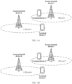
- Embodiments of this application may be applied to a network architecture shown in FIG. 1A .
- the network architecture shown in FIG. 1A is a network architecture of a wireless communication system.
- the network architecture usually includes a terminal device and an access network device.
- a quantity of each type of devices and a form of each type of devices do not constitute a limitation on embodiments of this application.
- FIG. 1A includes an access network device 1, an access network device 2, and one or more terminal devices (where a terminal device 1 and a terminal device 2 are used as examples in the figure, the terminal device 1 is camped on an LTE cell 1, and the terminal device 2 is camped on an NR cell 1).
- the LTE cell 1 corresponds to the access network device 1.
- the access network device 1 provides the LTE cell 1, and provides a communication service for the terminal device 1 through the LTE cell 1.
- the NR cell 1 corresponds to the access network device 2.
- a dashed line in FIG. 1A represents a coverage area of a cell. For a same mark in the following figures, refer to the description.
- An LTE cell is a cell using an LTE communication standard
- an NR cell is a cell using an NR communication standard.
- a frequency range of the LTE cell 1 and a frequency range of the NR cell 1 overlap.
- the access network device 1 may send, through the LTE cell 1, a signal to one or more terminal devices (for example, the terminal device 1) camped on the LTE cell 1, and the access network device 2 may send, through the NR cell 1, a signal to one or more terminal devices (for example, the terminal device 2) camped on the NR cell 1.
- the access network device 2 sends a signal to the terminal device 2 through the NR cell 1
- the terminal device 1 may receive the signal sent by the access network device 2.
- the signal causes interference to communication between the terminal device 1 and the access network device 1. Therefore, the signal may be considered as an interference signal.
- the terminal device 1 increases power of a transmit signal of the terminal device 1. In this case, the uplink signal sent by the terminal device interferes with an uplink signal sent by another terminal device in the LTE cell 1.
- FIG. 1B is a schematic diagram of another network architecture according to an embodiment of this application.
- FIG. 1B includes an access network device 4, an access network device 5, and one or more terminal devices (where a terminal device 6 and a terminal device 5 are used as examples in the figure, the terminal device 6 is camped on an LTE cell 6, and the terminal device 5 is camped on an LTE cell 7).
- the LTE cell 6 corresponds to the access network device 4.
- the LTE cell 7 corresponds to the access network device 5.
- the access network device 5 provides the LTE cell 7, and provides a communication service for the terminal device 5 through the LTE cell 7.
- the LTE cell 6 and the LTE cell 7 are cells of a same standard, but a center frequency of a downlink reference signal of the LTE cell 6 is different from a center frequency of a downlink reference signal of the LTE cell 7, and a frequency range of the LTE cell 6 and a frequency range of the LTE cell 7 overlap.
- the frequency range of the LTE cell 6 is 2010 MHz to 2020 MHz, and the center frequency of the downlink reference signal of the LTE cell 6 is 2015 MHz; and the frequency range of the LTE cell 7 is 2010 MHz to 2040 MHz, and the center frequency of the downlink reference signal of the LTE cell 7 is 2020 MHz.
- intra-standard inter-frequency cells cells that have a same standard but different center frequencies of downlink reference signals may be referred to as intra-standard inter-frequency cells.
- the LTE cell 6 and the LTE cell 7 are intra-standard inter-frequency cells.
- Two cells that have a same center frequency of a downlink reference signal may be referred to as intra-frequency cells.
- the access network device 4 may send, through the LTE cell 6, a signal to one or more terminal devices (for example, the terminal device 6) camped on the LTE cell 6, and the access network device 5 may send, through the LTE cell 7, a signal to one or more terminal devices (for example, the terminal device 5) camped on the LTE cell 7.
- the access network device 5 sends a signal to the terminal device 5 through the LTE cell 7, because the frequency range of the LTE cell 6 overlaps with the frequency range of the LTE cell 7, the terminal device 6 may receive the signal sent by the access network device 5.
- the signal causes interference to communication between the terminal device 6 and the access network device 4. Therefore, the signal may be considered as an interference signal.
- the terminal device 6 increases power of a transmit signal of the terminal device 6.
- the uplink signal sent by the terminal device interferes with an uplink signal sent by another terminal device in the LTE cell 6.
- two cells provided by the access network device 5 may alternatively be both NR cells, and the two NR cells are intra-standard inter-frequency cells. In this case, for a manner of forming near-far interference to the terminal device 6, refer to the foregoing described manner. Details are not described herein again.
- FIG. 2A is a schematic diagram of another network architecture according to an embodiment of this application.
- FIG. 2A includes an access network device 3 and one or more terminal devices (where a terminal device 3 and a terminal device 4 are used as examples in the figure, the terminal device 3 is camped on an LTE cell 2, and the terminal device 4 is camped on an NR cell 2).
- the LTE cell 2 corresponds to the access network device 3. This may be understood as that the access network device 3 provides the LTE cell 2, and provides a communication service for the terminal device 3 through the LTE cell 2.
- the NR cell 2 corresponds to the access network device 3. This may be understood as that the access network device 3 provides the NR cell 2, and provides a communication service for the terminal device 4 through the NR cell 2.
- the access network device 3 may send, through the LTE cell 2, a signal to one or more terminal devices (for example, the terminal device 3) camped on the LTE cell 2, and the access network device 3 may send, through the NR cell 2, a signal to one or more terminal devices (for example, the terminal device 4) camped on the NR cell 2.
- the access network device 3 sends a signal to the terminal device 4 through the NR cell 2
- the terminal device 3 may receive the signal sent by the access network device 3.
- the signal causes interference to communication between the terminal device 3 and the access network device 3 through the LTE cell 2. Therefore, the signal may be considered as an interference signal.
- the terminal device 3 increases power of a transmit signal of the terminal device 3. In this case, the uplink signal sent by the terminal device interferes with an uplink signal sent by another terminal device in the LTE cell 2.
- FIG. 2B is a schematic diagram of another network architecture according to an embodiment of this application.
- FIG. 2B includes an access network device 6 and one or more terminal devices (where a terminal device 7 and a terminal device 8 are used as examples in the figure, the terminal device 7 is camped on an NR cell 3, and the terminal device 8 is camped on an NR cell 4).
- the NR cell 3 corresponds to the access network device 7.
- the NR cell 4 corresponds to the access network device 6.
- the access network device 6 provides the NR cell 4, and provides a communication service for the terminal device 8 through the NR cell 4.
- the NR cell 3 and the NR cell 4 are cells of a same standard, but a center frequency of a downlink reference signal of the NR cell 3 is different from a center frequency of a downlink reference signal of the NR cell 4, and a frequency range of the NR cell 3 and a frequency range of the NR cell 4 overlap.
- the NR cell 3 and the NR cell 4 are intra-standard inter-frequency cells.
- the access network device 6 may send, through the NR cell 3, a signal to one or more terminal devices (for example, the terminal device 7) camped on the NR cell 3, and the access network device 6 may send, through the NR cell 4, a signal to one or more terminal devices (for example, the terminal device 8) camped on the NR cell 4.
- the terminal device 7 may receive the signal sent by the access network device 6.
- the signal causes interference to communication between the terminal device 7 and the access network device 6 through the NR cell 3. Therefore, the signal may be considered as an interference signal.
- the terminal device 7 increases power of a transmit signal of the terminal device 7. In this case, the uplink signal sent by the terminal device interferes with an uplink signal sent by another terminal device in the NR cell 3.
- the two cells provided by the access network device 6 may alternatively be both LTE cells, and the two LTE cells are intra-standard inter-frequency cells.
- the two LTE cells are intra-standard inter-frequency cells.
- the wireless communication system in embodiments of this application includes, but is not limited to, a narrowband internet of things (narrow band-internet of things, NB-IoT) system, a global system for mobile communications (global system for mobile communications, GSM), an enhanced data rate for GSM evolution (enhanced data rate for GSM evolution, EDGE) system, a wideband code division multiple access (wideband code division multiple access, WCDMA) system, a code division multiple access 2000 (code division multiple access, CDMA2000) system, a time division-synchronization code division multiple access (time division-synchronization code division multiple access, TD-SCDMA) system, a long term evolution (long term evolution, LTE) system, a 5th generation (5th-generation, 5G) mobile communication system, or a future mobile communication system.
- NB-IoT narrowband internet of things
- GSM global system for mobile communications
- GSM evolution enhanced data rate for GSM evolution
- EDGE enhanced data rate for GSM evolution
- WCDMA wideband code
- the access network device in embodiments of this application may be a base station (Base Station, BS).
- the base station may provide a communication service for a plurality of terminal devices, and a plurality of base stations may also provide a communication service for a same terminal device.
- the base station is an apparatus deployed in a radio access network to provide a wireless communication function for a terminal device.
- the base station device may be a base station, a relay station, or an access point.
- the base station may be a base transceiver station (Base Transceiver Station, BTS) in a global system for mobile communications (Global System for Mobile Communications, GSM) or code division multiple access (Code Division Multiple Access, CDMA) network, may be an NB (NodeB) in wideband code division multiple access (Wideband Code Division Multiple Access, WCDMA), or may be an eNB or an eNodeB (Evolutional NodeB) in long term evolution (Long Term Evolution, LTE).
- the base station device may alternatively be a radio controller in a cloud radio access network (Cloud Radio Access Network, CRAN) scenario.
- the base station device may alternatively be a base station device in a future 5G network or an access network device in a future evolved PLMN network.
- the base station device may alternatively be a wearable device, a vehicle-mounted device, or the like.
- an apparatus configured to implement a function of the access network device may be the access network device, or may be an apparatus that can support the access network device in implementing the function, for example, a chip system.
- the apparatus may be installed in the access network device.
- the terminal device in embodiments of this application may also be referred to as a terminal, and may be a device having a wireless transceiver function.
- the terminal device in embodiments of this application may include user equipment (user equipment, UE), an access terminal, a UE unit, a UE station, a mobile station, a remote station, a remote terminal, a mobile device, a UE terminal, a terminal, a wireless communication device, a UE agent, or a UE apparatus that has a wireless communication function.
- the access terminal may be a cellular phone, a cordless phone, a Session Initiation Protocol (Session Initiation Protocol, SIP) phone, a wireless local loop (Wireless Local Loop, WLL) station, a personal digital assistant (Personal Digital Assistant, PDA), a handheld device having a wireless communication function, a computing device, another processing device connected to a wireless modem, a vehicle-mounted device, a wearable device, a terminal device in a future 5G network, or a terminal device in a future evolved PLMN.
- an apparatus configured to implement a function of the terminal may be a terminal, or may be an apparatus, for example, a chip system, that can support the terminal in implementing the function.
- the apparatus may be installed in the terminal.
- the chip system may include a chip, or may include a chip and another discrete component.
- a communication standard (or a standard for short) is a network standard used by a mobile terminal to perform data communication.
- communication standards include GSM and CDMA.
- 3G 3rd-generation mobile communication technology (the 3rd generation mobile communication technology, 3G)
- communication standards include time division-synchronous code division multiple access (Time Division-Synchronous Code Division Multiple Access, TD-SCDMA), WCDMA and CDMA2000 (Code Division Multiple Access 2000).
- communication standards include two standards: time division duplex long term evolution (Long Term Evolution Time-Division Duplex, LTE-TDD) and frequency division duplex long term evolution (Long Term Evolution Frequency-division duplex, LTE-FDD), where the LTE-TDD is also referred to as TD-LTE.
- LTE-TDD Long Term Evolution Time-Division Duplex
- LTE-FDD frequency division duplex long term evolution
- LTE-TDD Long Term Evolution Frequency-division duplex
- LTE-TDD Long Term Evolution Frequency-division duplex
- SA standalone
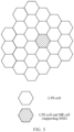
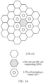
- FIG. 3 is a schematic diagram of another network architecture according to an embodiment of this application.
- a plurality of communication cells may be included in an area range shown in FIG. 3 .
- These communication cells use an LTE communication standard, and LTE network coverage is complete.
- an access network device in which some communication cells are located is selected to create a cell that uses an NR communication standard (an NR cell for short), and the newly created NR cell shares a part of frequency resources with a co-coverage cell that uses the LTE communication standard (an LTE cell for short) by using a dynamic spectrum sharing (Dynamic Spectrum Sharing, DSS) function.
- DSS Dynamic Spectrum Sharing
- FIG. 3 represents a coverage area of a cell.
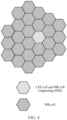
- FIG. 4 is a schematic diagram of another network architecture according to an embodiment of this application.
- An area range shown in FIG. 4 includes a plurality of communication cells, and some communication cells use an LTE communication standard.
- an access network device in which some LTE communication standard cells are located is selected to create an NR cell, and the newly created NR cell shares a part of frequency resources with a co-coverage LTE cell by using a DSS function.
- An access network device in which another communication cell is located directly creates an NR standard cell, so that NR network coverage is complete.
- a cell deployment range of the LTE communication standard is gradually reduced. It should be noted that, for a network architecture formed by a neighboring LTE cell supporting the DSS and a neighboring NR cell not supporting the DSS in FIG. 4 , refer to the network architectures shown in FIG. 1A and FIG. 2A .
- FIG. 5 is a schematic diagram of another network architecture according to an embodiment of this application.
- An area range shown in FIG. 5 includes a plurality of communication cells.
- a communication cell in a left area of these communication cells uses an LTE communication standard
- a communication cell in a right area of these communication cells uses an NR communication standard.
- Evolution to NR in a manner of LTE spectrum concession means that a frequency occupation range of the LTE communication standard is gradually reduced, and a frequency occupation range of the NR communication standard is gradually increased.
- a network architecture formed by a neighboring LTE cell and a neighboring NR cell in FIG. 5 refer to the network architectures shown in FIG. 1A and FIG. 2A .
- FIG. 6A and FIG. 6B are schematic diagrams of some other network architectures according to embodiments of this application. Area ranges shown in FIG. 6A and FIG. 6B include a plurality of communication cells, and an LTE network and an NR network with full coverage are deployed in these communication cells by using a DSS function.
- the LTE network may be dynamically selected to be disabled based on load (which may be understood as not using an LTE communication standard for communication, and reference may be made to FIG. 6A ) or the NR network may be dynamically selected to be disabled based on load (which may be understood as not using an NR communication standard for communication, and reference may be made to FIG.
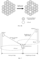
- FIG. 7 is a schematic diagram of another network architecture according to an embodiment of this application.
- the network architecture shown in FIG. 1A may be used as an example of the network architecture shown in FIG. 7 .
- the network architecture shown in FIG. 7 includes an antenna 1 of an access network device (where reference may be made to the access network device 1 in FIG. 1A ), an antenna 2 of an access network device (where reference may be made to the access network device 2 in FIG. 1A ), and a terminal device 1 (where reference may be made to the terminal device 1 in FIG. 1A ).
- the antenna 1 provides a communication signal for a terminal device accessing an LTE cell
- the antenna 2 provides a communication signal for a terminal device accessing an NR cell.
- the access network device to which the antenna 1 belongs and the access network device to which the antenna 2 belongs may be a same access network device, or may be different access network devices.
- both the LTE cell and the NR cell are located on a frequency band F1, and the terminal device 1 originally accesses the LTE cell.
- the antenna 1 sends a signal (namely, a service signal) to the terminal device 1 accessing the LTE cell through the LTE cell, and the antenna 2 may send a signal to one or more terminal devices that access the NR cell through the NR cell.
- the terminal device 1 may receive the signal sent by the antenna 2.
- the signal is a neighboring cell signal received by the terminal device 1.
- the signal causes interference to communication between the terminal device 1 and the antenna 1. Therefore, the signal may be considered as an interference signal.
- the service signal that is sent by the LTE cell and that is received by the terminal device 1 becomes weaker, and a service signal (which may be understood as an interference signal) sent by the NR cell becomes stronger.
- the terminal device Because in both LTE and NR communication systems, intra-frequency measurement and handover in a same communication standard are performed to ensure that a mobile terminal can always be in a cell with a strongest signal in the same communication standard, the terminal device cannot perform inter-standard intra-frequency measurement without additional power consumption. Therefore, the terminal device keeps camping on the LTE cell before a specific condition (for example, signal quality of a serving cell is higher than a preset value) is met. For the terminal device, the LTE cell on which the terminal device is camped is far, and the neighboring NR cell is near, which causes the near-far effect.
- a specific condition for example, signal quality of a serving cell is higher than a preset value
- strength of the service signal provided by the LTE cell is weaker than strength of a neighboring cell signal of the NR cell, and the neighboring cell signal of the NR cell causes strong interference to the service signal received by the terminal device.
- the terminal device 1 increases power of a transmit signal of the terminal device 1. In this case, the uplink signal sent by the terminal device interferes with an uplink signal sent by another terminal device in the LTE cell.
- FIG. 8 is a schematic diagram of another network architecture according to an embodiment of this application.
- the network architecture shown in FIG. 8 includes an LTE cell 1, an LTE cell 2, an LTE cell 3, an NR cell 1, and a terminal device 1. Both the LTE cell 1 and the NR cell 1 are located on a frequency band F1, and both the LTE cell 2 and the LTE cell 3 are located on a frequency band F2.
- the terminal device accesses the LTE cell 1 .
- Communication signals sent through the LTE cell 2, the LTE cell 3, and the NR cell 1 are all neighboring cell signals for the terminal device 1. However, because the signals sent through the LTE cell 2 and the LTE cell 3 and the signal sent through the LTE cell 1 are not on a same frequency band, the signals sent through the LTE cell 2 and the LTE cell 3 are not interference signals for the terminal device 1. The communication signal sent through the NR cell 1 and the communication signal sent through the LTE cell 1 are on a same frequency band. Therefore, the communication signal sent through the NR cell 1 is an interference signal for the terminal device 1.
- a service signal that is sent by the LTE cell 1 and that is received by the terminal device 1 becomes weaker, and the neighboring cell signal (which may be understood as an interference signal) sent by the NR cell 1 becomes stronger.
- the neighboring cell signal which may be understood as an interference signal
- quality of the signal that is of the NR cell 1 and received by the terminal device 1 is stronger than quality of the signal of the LTE cell 1, and a near-far effect is triggered.
- the quality of the signal of the serving cell (the LTE cell 1) is higher than or equal to a preset value, the terminal device 1 keeps camping on the LTE cell 1.
- the terminal device 6 Similar to LTE and NR intra-frequency networking, when frequency ranges of neighboring intra-standard inter-frequency cells overlap, the terminal device is also vulnerable to the near-far interference.
- the LTE cell 6 and the LTE cell 7 in FIG. 1B are used as an example.
- the terminal device 6 cannot detect the downlink reference signal of the LTE cell 7. Therefore, the terminal device 6 keeps camping on the LTE cell 6 before a specific condition (for example, signal quality of the LTE cell 6 is higher than a preset value) is met.
- the LTE cell 6 on which the terminal device 6 is camped is far, and the neighboring LTE cell 7 is near, which causes the near-far effect.
- strength of a service signal provided by the LTE cell 6 is weaker than strength of a neighboring cell signal of the LTE cell 7, and the neighboring cell signal of the LTE cell 7 causes strong interference to the service signal received by the terminal device 6.
- the terminal device 6 increases power of a transmit signal of the terminal device 6. In this case, the uplink signal sent by the terminal device 6 interferes with an uplink signal sent by another terminal device in the LTE cell 6.
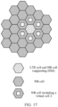
- an LTE cell 4 is created in the NR cell 1 (where reference may be made to a network architecture shown in FIG. 9 ).
- the LTE cell 4 occupies some time-frequency resources originally belonging to the NR cell 1, and sends a downlink reference signal to a terminal device.
- the terminal device may detect existence of the LTE cell 4 and signal quality of the LTE cell 4 based on the downlink reference signal sent by the LTE cell 4. Because the LTE cell 4 occupies some time-frequency resources originally belonging to the NR cell 1 to send the downlink reference signal, the signal quality of the LTE cell 4 may be considered as signal quality of the NR cell 1.
- an intra-frequency measurement report fed back by the terminal device to a first access network device includes information about the LTE cell 4.
- the signal quality of the LTE cell 4 is higher than the signal quality of the LTE cell 1, and this indicates that a neighboring cell signal of the NR cell 1 that is an intra-frequency inter-standard cell of the LTE cell 1 is stronger than a serving signal of the LTE cell 1. In this case, near-far interference is caused.
- the access network device 1 may determine, based on the information about the LTE cell 4 in the intra-frequency measurement report, that the intra-frequency inter-standard neighboring cell signal is stronger than the serving signal in an environment in which the mobile terminal is currently located. Then, the access network device 1 migrates the terminal device 1 to an intra-standard inter-frequency cell or an inter-standard cell, to avoid the near-far interference.
- FIG. 10 is a flowchart of a cell measurement method according to an embodiment of this application.
- the method includes the following steps. It should be noted that in the following content, a first access network device may be the access network device 1 in FIG. 9 , a first serving cell may be the LTE cell 1 in FIG. 9 , a virtual cell may be the LTE cell 4 in FIG. 9 , a second serving cell may be the NR cell 1 in FIG. 9 , and a terminal device may be the terminal device 1 in FIG. 9 .
- the serving cell is a cell that can provide services such as access and uplink/downlink data transmission for the terminal device, and may also be referred to as a normal cell or a cell.
- the virtual cell is a cell that only sends a downlink signal to the terminal device, so that the terminal device performs cell measurement.
- the virtual cell does not provide the access service or the uplink/downlink data transmission service for the terminal device.
- the virtual cell may also be referred to as an unreal cell, a simulated cell, or the like.
- the foregoing names are merely used to distinguish between the two types of cells. In an actual application process, there may be other names. This is not limited in this embodiment.
- the first access network device sends first measurement control information to the terminal device through the first serving cell.
- the first serving cell is a communication cell currently accessed (or referred to as camped on) by the terminal device.
- the first access network device sends the first measurement control information to the terminal device through the first serving cell. It should be noted that, in a process in which the terminal device camps on the first serving cell, the terminal device continuously performs intra-frequency measurement based on the first measurement control information. The intra-frequency measurement does not cause extra function consumption of the terminal device.
- the first measurement control information includes indication information, and the indication information indicates a type of a measurement event.
- the type of the measurement event may include an A1 event (indicating that signal quality of a serving cell is higher than a specific threshold), an A2 event (indicating that the signal quality of the serving cell is lower than a specific threshold), an A3 event (indicating that signal quality of an intra-frequency neighboring cell is higher than the signal quality of the serving cell), and the like.
- the first measurement control information includes indication information indicating the A3 event.
- the first measurement control information indicates the terminal device to feed back a first measurement report to the first access network device when the signal quality of the intra-frequency neighboring cell is higher than the signal quality of the serving cell.
- the signal quality may also be understood as signal strength.
- Reference signal received power (Reference Signal Received Power, RSRP) of a cell may be a reference indicator of the signal quality.
- the signal quality may also have another reference indicator. This is not limited in this application.
- the first measurement control information indicates the terminal device to measure quality of a downlink reference signal of the virtual cell.
- a center frequency of a downlink reference signal of the first serving cell is the same as a center frequency of the downlink reference signal of the virtual cell.
- the terminal device may be indicated to perform intra-frequency detection based on the center frequency of the downlink reference signal of the virtual cell, so that the terminal device can detect the virtual cell.
- a frequency range of the virtual cell is included in a frequency range of the second serving cell, and the frequency range of the second serving cell overlaps with a frequency range of the first serving cell.
- a standard of the second serving cell is different from a standard of the first serving cell (for example, in correspondence to a case shown in FIG. 9 ).
- a standard of the second serving cell is the same as a standard of the first serving cell and a center frequency of a downlink reference signal of the second serving cell is different from the center frequency of the downlink reference signal of the first serving cell (for example, in correspondence to a case shown in FIG. 1B ).
- the communication standard supported by the first serving cell is an LTE communication standard
- the communication standard supported by the second serving cell is an NR communication standard
- the first measurement control information may include a center frequency of a downlink reference signal of a cell and measurement bandwidth.
- the center frequency of the downlink reference signal of the cell is the same as the center frequency of the downlink reference signal of the first serving cell and the center frequency of the downlink reference signal of the virtual cell, and the measurement bandwidth is bandwidth of the virtual cell.
- the bandwidth of the virtual cell is one of 1.4 MHz, 3 MHz, 5 MHz, 10 MHz, 15 MHz and 20 MHz.
- a first frequency range may be determined based on the center frequency of the downlink reference signal of the cell and the measurement bandwidth.
- the first frequency range is the same as the frequency range of the virtual cell.
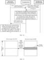
- FIG. 11 is a schematic diagram of frequency ranges of a first serving cell, a virtual cell, and a second serving cell according to an embodiment of this application.
- a center frequency of a downlink reference signal of the first serving cell is the same as a center frequency of a downlink reference signal of the virtual cell.
- a frequency range of the second serving cell overlaps with a frequency range of the first serving cell.
- the frequency range of the first serving cell and the frequency range of the second serving cell may be the same, for example, both may be 2600 MHz to 2620 MHz.
- the frequency range of the first serving cell may alternatively be different from the frequency range of the second serving cell.
- the frequency range of the first serving cell is 2600 MHz to 2620 MHz
- the frequency range of the second serving cell is 2600 MHz to 2640 MHz.
- the communication standard supported by the first serving cell is an NR communication standard
- the communication standard supported by the second serving cell is an LTE communication standard
- the first measurement control information may include a center frequency of a downlink reference signal (which may be specifically a demodulation reference signal (Demodulation Reference Signal, DMRS)) in a synchronization signal and physical broadcast channel block (SSB).
- DMRS demodulation Reference Signal
- the included center frequency of the downlink reference signal in the SSB is the same as a center frequency of a downlink reference signal in an SSB of the first serving cell and a center frequency of a downlink reference signal in an SSB of the virtual cell.
- the first measurement control information may not need to include measurement bandwidth information.
- the SSB of the virtual cell is 20 RBs, and bandwidth of the virtual cell may have a plurality of values. This is not limited in this embodiment of this application.
- a first frequency range may be determined based on the center frequency of the downlink reference signal in the SSB.
- the first frequency range is the same as the frequency range of the virtual cell.
- FIG. 12 is another schematic diagram of frequency ranges of a first serving cell, a virtual cell, and a second serving cell according to an embodiment of this application.
- a center frequency of a downlink reference signal in an SSB of the first serving cell is the same as a center frequency of a downlink reference signal in an SSB of the virtual cell.
- a frequency range of the second serving cell overlaps with a frequency range of the first serving cell.
- the frequency range of the first serving cell and the frequency range of the second serving cell may be the same, for example, both may be 2600 MHz to 2620 MHz.
- the frequency range of the first serving cell may alternatively be different from the frequency range of the second serving cell.
- the frequency range of the second serving cell is 2600 MHz to 2620 MHz
- the frequency range of the first serving cell is 2600 MHz to 2640 MHz.
- the first access network device may generate the first measurement control information based on a center frequency (which may further include measurement bandwidth) that is of a downlink reference signal of the virtual cell and that is sent by a second access network device.
- a center frequency (which may further include measurement bandwidth) that is of a downlink reference signal of the virtual cell and that is sent by a second access network device.
- a second access network device when constructing a virtual cell, may construct the virtual cell based on the center frequency of the downlink reference signal of the first serving cell and the measurement bandwidth, or may construct the virtual cell based on the center frequency of the downlink reference signal in the SSB of the first serving cell.
- the second access network device sends a signal to the terminal device through the virtual cell and the second serving cell.
- the virtual cell may be understood as an unreal cell or a simulated cell constructed by the second access network device.
- a purpose of constructing the virtual cell is mainly to enable the terminal device to discover the virtual cell and measure signal quality of the virtual cell in a process of performing the intra-frequency measurement.
- existence of the virtual cell may approximately represent existence of the intra-frequency inter-standard second serving cell.
- the signal quality of the virtual cell may approximately represent signal quality of the intra-frequency inter-standard second serving cell.
- the purpose of constructing the virtual cell is not to provide an access service (or referred to as a communication service) for the terminal device.
- the second access network device sends a downlink signal through the virtual cell, where the downlink signal includes the downlink reference signal of the virtual cell.
- the downlink signal is used to enable the terminal device to discover the virtual cell and detect the signal quality of the virtual cell.
- the second access network device sends a communication signal through the second serving cell, and the communication signal is used to provide a communication service for another terminal device accessing the second serving cell.
- signals sent by the second access network device through the virtual cell and the second serving cell are neighboring cell signals.
- the second serving cell is an inter-standard communication cell (or an intra-standard inter-frequency cell)
- the terminal device cannot detect the signal sent by the second access network device through the second serving cell.
- a time-frequency resource occupied by the signal (for example, the downlink reference signal) sent by the second access network device through the virtual cell is different from a time-frequency resource occupied by the signal sent through the second serving cell. In this manner, interference caused by the communication signal sent through the second serving cell to the downlink reference signal sent through the virtual cell can be avoided, and a measurement result of the intra-frequency measurement is not affected.
- the second access network device sends, through the second serving cell, indication information to the terminal device accessing the second serving cell.
- the indication information indicates an available time-frequency resource of the terminal device accessing the second serving cell, and the available time-frequency resource is different from a time-frequency resource occupied by the downlink signal of the virtual cell or indicates that the terminal device accessing the second serving cell does not use a time-frequency resource occupied by the downlink signal sent by the virtual cell.
- An indication manner of the indication information may include a dynamic scheduling indication and a semi-persistent resource indication.
- the dynamic scheduling indication means that the second access network device sends, in the second serving cell, DCI (Downlink Control Information) information (which is understood as the indication information) through a physical downlink control channel (Physical Downlink Control Channel, PDCCH).
- DCI Downlink Control Information
- PDCCH Physical Downlink Control Channel
- the DCI information indicates the available time-frequency resource of the terminal device accessing the second serving cell, and the available time-frequency resource is different from the time-frequency resource occupied by the downlink signal sent by the virtual cell.
- the semi-persistent resource indication means that the second access network device sends an RRC reconfiguration message (which is understood as the indication information) in the second serving cell.
- the RRC reconfiguration message indicates the terminal device accessing the second serving cell not to use the time-frequency resource occupied by the downlink signal sent by the virtual cell.
- the second access network device may use any indication manner, or may use different indication manners for different channels of the virtual cell.
- the virtual cell does not provide an access service for the terminal device.
- the second access network device does not need to divide a large quantity of time-frequency resources for the virtual cell to support the communication service for the terminal device, and can reserve as many time-frequency resources as possible for the second serving cell to support the communication service for the terminal device accessing the second serving cell.
- the communication standard supported by the virtual cell is the LTE communication standard.
- the downlink signal includes the downlink reference signal of the virtual cell.
- the downlink reference signal includes a cell-specific reference signal (Cell-specific Reference Signal, CRS).
- CRS Cell-specific Reference Signal
- the CRS is used by the terminal device to detect the signal quality of the virtual cell.
- the downlink signal further includes one or more of a primary synchronization signal (Primary Synchronization Signal, PSS), a secondary synchronization signal (Secondary Synchronization Signal, SSS), a physical broadcast channel (Physical Broadcast Channel, PBCH), and system information block (System Information Block, SIB) 1 information.
- PSS Primary Synchronization Signal
- SSS secondary synchronization signal
- PBCH Physical Broadcast Channel
- SIB System Information Block
- the PSS and the SSS are used by the terminal device to discover (or detect) the virtual cell.
- the physical broadcast channel is used by the terminal device to detect a system information block.
- the system information block carries indication information (for example, a "barred (Barred)" identifier), and the indication information indicates that the virtual cell does not provide an access service for the terminal device.
- indication information for example, a "barred (Barred)" identifier
- the system information block includes system information.
- a cell may have a plurality of system information blocks, and these system information blocks carry different information, for example, the SIB 1.
- the SIB 1 mainly carries configuration information of some cells, for example, information related to random access, information related to a PDCCH, information related to other information blocks, information about a cell accessed by the UE, and identification information of the cell.
- the second access network device sends only the PSS, the SSS, and the CRS through the virtual cell, so that the virtual cell does not provide the access service for the terminal.
- the communication standard supported by the virtual cell is the NR communication standard.
- the downlink reference signal in the downlink signal is a demodulation reference signal (DMRS), the downlink signal is a synchronization signal and physical broadcast channel block (SSB), and the SSB includes the DMRS.
- the SSB is used by the terminal device to discover (or detect) the virtual cell and detect the signal quality of the virtual cell. Specifically, a radio frequency of the terminal device retrieves, at a center frequency location of the SSB, a PSS and an SSS in the SSB to discover the cell, and detects the signal quality of the virtual cell by using the demodulation reference signal in the SSB.
- step S101 and step S102 there is no limitation on a sequence of performing step S101 and step S102.
- the terminal device measures the neighboring cell signal based on the first measurement control information.
- the terminal device may determine, based on the first measurement control information, the measurement event and the first frequency range in which the neighboring cell signal that needs to be measured is located.
- the terminal device measures the neighboring cell signal in the first frequency range, and determines a cell identifier and signal quality of the measured neighboring cell, to obtain one or more measurement results.
- S104 The terminal device generates the first measurement report based on the measurement result.
- the first measurement report includes information about one or more cells detected by the terminal device, and quality of a downlink reference signal of the one or more cells is higher than quality of the downlink reference signal of the first serving cell. In some embodiments, the first measurement report includes information about all cells whose downlink reference signal quality is higher than the quality of the downlink reference signal of the first serving cell.
- the first measurement control information includes indication information indicating a maximum value (for example, N) of a quantity of neighboring cells in the first measurement report.
- the first measurement report includes information about a maximum of N cells. Signal quality of the included N cells is stronger than signal quality of a remaining measured neighboring cell.
- the first measurement report indicates the quality of the downlink reference signal of the virtual cell.
- the first measurement report includes a measurement result of the virtual cell, indicating that quality of the downlink reference signal of the virtual cell is higher than the quality of the downlink reference signal of the first serving cell.
- the signal quality of the virtual cell may be considered as the signal quality of the second serving cell.
- the signal sent through the second serving cell affects communication between the terminal device and the first network device, and may easily cause near-far interference.
- S105 The terminal device sends the first measurement report to the first access network device.
- the first access network device migrates the terminal device to a third serving cell when the quality of the downlink reference signal of the virtual cell is higher than the quality of the downlink reference signal of the first serving cell.
- a standard of the third serving cell is the same as the standard of the first serving cell, and a center frequency of a downlink reference signal of the third serving cell is different from the center frequency of the downlink reference signal of the first serving cell, or a standard of the third serving cell is different from the standard of the first serving cell.
- the third serving cell and the first serving cell are intra-standard inter-frequency cells or inter-standard cells. It should be noted that the third serving cell may be the second serving cell, or may be another serving cell.
- the quality of the downlink reference signal of the virtual cell is higher than the quality of the downlink reference signal of the first serving cell may be understood as that the first measurement report includes information about the virtual cell.
- the terminal device reports the information about the virtual cell only when the quality of the downlink reference signal of the virtual cell is higher than the quality of the downlink reference signal of the first serving cell.
- the first measurement report may implicitly indicate that the quality of the downlink reference signal of the virtual cell is higher than the quality of the downlink reference signal of the first serving cell.
- the following describes some possible prerequisites.
- the first access network device migrates the terminal device to the third serving cell when the quality of the downlink reference signal of the virtual cell is higher than the quality of the downlink reference signal of the first serving cell, and the quality of the downlink reference signal of the virtual cell is higher than quality of a downlink reference signal of another cell included in the first measurement report.
- the foregoing case indicates that a neighboring cell signal of the second serving cell that has a same frequency and different standards with the first serving cell is the strongest in detected neighboring cell signals, and the neighboring cell signal of the second serving cell causes strong interference to a serving signal of the first serving cell. In this case, the near-far interference problem is easily caused.
- the first access network device migrates the terminal device to the third serving cell when the quality of the downlink reference signal of the virtual cell is higher than the quality of the downlink reference signal of the first serving cell and the quality of the downlink reference signal of the virtual cell is higher than a preset value.
- the preset value may be a preset threshold relative to signal quality of the camped cell, or may be a preset absolute threshold. The foregoing case indicates that the signal quality of the virtual cell is strong, and interference to a serving signal of the first serving cell is strong. In this case, the near-far interference problem is easily caused.
- the first access network device migrates the terminal device to the third serving cell may be: The first access network device hands over the terminal device to the third serving cell.
- the manner may be that the first access network device redirects the terminal device to the third serving cell.
- the following describes some possible implementations in which the first access network device migrates the terminal device to the third serving cell.
- the first access network device sends second measurement control information to the terminal device, where the second measurement control information indicates the terminal device to measure quality of the downlink reference signal of the third serving cell.
- the first access network device receives a second measurement report from the terminal device, where the second measurement report indicates the quality of the downlink reference signal of the third serving cell.
- the first access network device migrates the terminal device to the third serving cell based on the second measurement report.
- the second measurement report includes information about one or more intra-standard inter-frequency cells or inter-standard cells that meet a measurement condition.
- the first access network device selects the third serving cell from the one or more intra-standard inter-frequency cells or inter-standard cells.
- the first access network device stores one or more cell identifiers of one or more serving cells neighboring to the first serving cell.
- the cell identifiers of the one or more serving cells include a cell identifier of the third serving cell. That the first access network device migrates the terminal device to the third serving cell includes: The first access network device selects the third serving cell from the one or more stored serving cells neighboring to the first serving cell; and the first access network device migrates the terminal device to the third serving cell.
- the cell identifiers of the one or more serving cells neighboring to the first serving cell may be stored in a neighboring cell list.
- the cell identifier may be a physical cell identifier (Physical Cell Identifier, PCI).
- the first access network device determines that the first measurement report includes the information about the virtual cell.
- the first access network device stores a cell identifier of the virtual cell, and a first measurement result includes the cell identifier of the virtual cell.
- the first access network device may store a virtual cell list, and the virtual cell list includes preset cell identifiers of multiple virtual cells.
- the first access network device stores the cell identifiers of the one or more serving cells neighboring to the first serving cell, a first measurement result includes a cell identifier of the virtual cell, and the cell identifier of the virtual cell is different from the cell identifiers of the one or more serving cells.
- the cell identifiers of the one or more serving cells neighboring to the first serving cell may be stored in a neighboring cell list.
- the neighboring cell list stores the preset cell identifiers of the one or more cells that are neighboring to the first serving cell and that can support the communication service of the terminal device. That the cell identifier is different from the cell identifiers of the one or more serving cells indicates that the virtual cell is not a serving cell.
- the network architecture corresponding to FIG. 1A is used as an example to describe implementation steps of the cell measurement method provided in embodiments of this application.
- the method may be further applied to the network architecture corresponding to FIG. 1B .
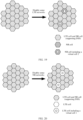
- an LTE cell 8 is created in the LTE cell 7 (where reference may be made to a network architecture shown in FIG. 13 ).
- the LTE cell 8 may be considered as the virtual cell described in the foregoing content
- the LTE cell 6 may be considered as the first serving cell described in the foregoing content
- the LTE cell 7 may be considered as the second serving cell described in the foregoing content
- the terminal device 6 may be considered as the terminal device described in the foregoing content.
- the LTE cell 6 corresponds to the access network device 4, and both the LTE cell 7 and the LTE cell 7 correspond to the access network device 5.
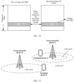
- the method may be further applied to the network architecture corresponding to FIG. 2A .
- an LTE cell 5 is created in the NR cell 2 (where reference may be made to a network architecture shown in FIG. 14 ).
- the LTE cell 5 may be considered as the virtual cell described in the foregoing content
- the LTE cell 2 may be considered as the first serving cell described in the foregoing content
- the NR cell 2 may be considered as the second serving cell described in the foregoing content
- the terminal device 3 may be considered as the terminal device described in the foregoing content.
- the LTE cell 5, the LTE cell 2, and the NR cell 2 are all corresponding to the access network device 3.
- the foregoing described operations performed by the first access network device namely, the access network device 1 and the second access network device (namely, the access network device 2) are performed by the access network device 3.
- the access network device 3 further sends a downlink signal through the virtual cell.
- the access network device 3 further sends a communication signal through the second serving cell.
- the access network device 3 sends, further through the second serving cell, indication information to a terminal device accessing the second serving cell.
- the indication information indicates an available time-frequency resource of the terminal device accessing the second serving cell, and the available time-frequency resource is different from a time-frequency resource occupied by the downlink signal sent by the virtual cell or indicates that the terminal device accessing the second serving cell does not use a time-frequency resource occupied by the downlink signal sent by the virtual cell.
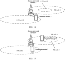
- the method may be further applied to the network architecture corresponding to FIG. 2B .
- an NR cell 5 is created in the NR cell 4 (where reference may be made to a network architecture shown in FIG. 15 ).
- the NR cell 5 may be considered as the virtual cell described in the foregoing content
- the NR cell 3 may be considered as the first serving cell described in the foregoing content
- the NR cell 4 may be considered as the second serving cell described in the foregoing content
- the terminal device 7 may be considered as the terminal device described in the foregoing content.
- the NR cell 4, the NR cell 3, and the NR cell 5 all correspond to the access network device 6.
- the access network device 6 not only needs to perform the foregoing described operations performed by the first access network device (namely, the access network device 1), but also needs to perform the foregoing described operations performed by the second access network device (namely, the access network device 2).
- the virtual cell and the second serving cell are the cells of the communication apparatus, and the sending unit 2101 is further configured to send a downlink signal of the virtual cell, where the downlink signal includes the downlink reference signal of the virtual cell.
- the downlink reference signal includes a cell-specific reference signal CRS.
- the downlink signal further includes one or more of a PSS, an SSS, and a system information block
- the system information block includes indication information indicating that the virtual cell does not provide an access service for the terminal device.
- the downlink reference signal is a DMRS
- the downlink signal is an SSB
- the SSB includes the DMRS
- the sending unit 2101 is further configured to send, through the second serving cell, indication information to a terminal device accessing the second serving cell.
- the indication information indicates an available time-frequency resource of the terminal device accessing the second serving cell, and the available time-frequency resource is different from a time-frequency resource occupied by the downlink signal of the virtual cell or indicates that the terminal device accessing the second serving cell does not use a time-frequency resource occupied by the downlink signal sent by the virtual cell.
- operations performed by the units of the communication apparatus shown in FIG. 21 may be the related content in the foregoing method embodiments. Details are not described herein again.
- the foregoing units may be implemented by hardware, software, or a combination of software and hardware.
- functions of the sending unit 2101, the receiving unit 2102, and the migration unit 2103 in the foregoing content may be implemented by one or more processors in the communication apparatus 210.
- the communication apparatus shown in FIG. 21 may determine, based on the first measurement report, that the quality of the downlink reference signal of the virtual cell is higher than the quality of the downlink reference signal of the first serving cell. In this case, near-far interference may be caused. In this case, the communication apparatus migrates the terminal device to the third serving cell, to avoid near-far interference to the terminal device.
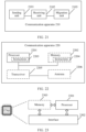
- FIG. 22 is a schematic diagram of a structure of another communication apparatus according to an embodiment of this application.
- a communication apparatus 220 may be an access network device, or may be an apparatus in the access network device, or may be an apparatus that can be used with a terminal device.
- the communication apparatus 220 may be a chip, a chip system, a processor, or the like that supports the access network device in implementing the foregoing method.
- the communication apparatus 220 may be configured to implement the method described in the foregoing method embodiments. For details, refer to the descriptions in the foregoing method embodiments.
- the communication apparatus 220 may include one or more processors 2201.
- the processor 2201 may be a general-purpose processor, a dedicated processor, or the like.
- the processor 2201 may be configured to control the communication apparatus (for example, the access network device or the chip of the access network device), execute a software program, and process data of the software program.
- the communication apparatus 220 may include one or more memories 2202.
- the one or more memories 2202 may store instructions 2204.
- the instructions may be run on the processor 2201, to enable the communication apparatus 220 to perform the method described in the foregoing method embodiments.
- the memory 2202 may further store data.
- the processor 2201 and the memory 2202 may be separately disposed, or may be integrated together.
- the communication apparatus 220 may further include a transceiver 2205 and an antenna 2206.
- the transceiver 2205 may be referred to as a transceiver unit, a transceiver machine, a transceiver circuit, or the like, and is configured to implement a transceiver function.
- the transceiver 2205 may include a receiver and a transmitter.
- the receiver may be referred to as a receiver machine, a receiver circuit, or the like, and is configured to implement a receiving function.
- the transmitter may be referred to as a transmitter machine, a transmitter circuit, or the like, and is configured to implement a sending function.
- the processor 2201 is further configured to perform the following operations.
- the processor 2201 is configured to send, by using the transceiver 2205, first measurement control information to a terminal device through a first serving cell.
- the first measurement control information indicates the terminal device to measure quality of a downlink reference signal of a virtual cell.
- a center frequency of a downlink reference signal of the first serving cell is the same as a center frequency of the downlink reference signal of the virtual cell.
- a frequency range of the virtual cell is included in a frequency range of a second serving cell, and the frequency range of the second serving cell overlaps with a frequency range of the first serving cell.
- a standard of the second serving cell is different from a standard of the first serving cell, or a standard of the second serving cell is the same as a standard of the first serving cell and a center frequency of a downlink reference signal of the second serving cell is different from the center frequency of the downlink reference signal of the first serving cell.
- the virtual cell and the second serving cell are cells of the communication apparatus, or the virtual cell and the second serving cell are cells of a second access network device.
- the processor 2201 is configured to receive, by using the transceiver 2205, a first measurement report from the terminal device, where the first measurement report indicates the quality of the downlink reference signal of the virtual cell.
- the processor 2201 is configured to migrate the terminal device to a third serving cell when the quality of the downlink reference signal of the virtual cell is higher than quality of the downlink reference signal of the first serving cell.
- a standard of the third serving cell is the same as the standard of the first serving cell, and a center frequency of a downlink reference signal of the third serving cell is different from the center frequency of the downlink reference signal of the first serving cell, or a standard of the third serving cell is different from the standard of the first serving cell.
- the operations performed by the processor 2201 may be the related content in the foregoing method embodiments. Details are not described herein again.
- the transceiver may be a transceiver circuit, an interface, or an interface circuit.
- the transceiver circuit, the interface, or the interface circuit configured to implement the receiving and sending functions may be separated, or may be integrated together.
- the transceiver circuit, the interface, or the interface circuit may be configured to read and write code/data.
- the transceiver circuit, the interface, or the interface circuit may be configured to transmit or transfer a signal.
- the processor 2201 may store instructions 2203.
- the communication apparatus 220 is enabled to perform the method described in the foregoing method embodiments.
- the instructions 2203 may be fixed in the processor 2201. In this case, the processor 2201 may be implemented by hardware.
- the communication apparatus 220 may include a circuit.
- the circuit may implement a sending, receiving, or communication function in the foregoing method embodiments.
- the processor and the transceiver that are described in this application may be implemented on an integrated circuit (integrated circuit, IC), an analog IC, a radio frequency integrated circuit RFIC, a hybrid signal IC, an application-specific integrated circuit (application-specific integrated circuit, ASIC), a printed circuit board (printed circuit board, PCB), an electronic device, or the like.
- integrated circuit integrated circuit, IC
- analog IC analog IC
- radio frequency integrated circuit RFIC radio frequency integrated circuit
- RFIC radio frequency integrated circuit
- hybrid signal IC an application-specific integrated circuit
- ASIC application-specific integrated circuit
- PCB printed circuit board
- an electronic device or the like.
- the communication apparatus described in the foregoing embodiments may be an access point or a station. However, a scope of the communication apparatus described in this application is not limited thereto, and a structure of the communication apparatus may not be limited by FIG. 22 .
- the communication apparatus may be an independent device or may be a part of a large device.
- the communication apparatus may be:
- a chip 2300 shown in FIG. 23 includes a processor 2301 and an interface 2302. There may be one or more processors 2301, and there may be a plurality of interfaces 2302.
- the chip is configured to implement a function of the first access network device in embodiments of this application.
- the interface 2302 is configured to send first measurement control information to a terminal device through a first serving cell.
- the first measurement control information indicates the terminal device to measure quality of a downlink reference signal of a virtual cell.
- a center frequency of a downlink reference signal of the first serving cell is the same as a center frequency of the downlink reference signal of the virtual cell.
- a frequency range of the virtual cell is included in a frequency range of a second serving cell, and the frequency range of the second serving cell overlaps with a frequency range of the first serving cell.
- a standard of the second serving cell is different from a standard of the first serving cell, or a standard of the second serving cell is the same as a standard of the first serving cell and a center frequency of a downlink reference signal of the second serving cell is different from the center frequency of the downlink reference signal of the first serving cell.
- the virtual cell and the second serving cell are cells of the first access network device, or the virtual cell and the second serving cell are cells of a second access network device.
- the interface 2302 receives a first measurement report from the terminal device, where the first measurement report indicates the quality of the downlink reference signal of the virtual cell.
- the processor 2301 is configured to migrate the terminal device to a third serving cell when the quality of the downlink reference signal of the virtual cell is higher than quality of the downlink reference signal of the first serving cell.
- a standard of the third serving cell is the same as the standard of the first serving cell, and a center frequency of a downlink reference signal of the third serving cell is different from the center frequency of the downlink reference signal of the first serving cell, or a standard of the third serving cell is different from the standard of the first serving cell.
- the chip further includes a memory 2303, and the memory 2303 is configured to store program instructions and data that are necessary for the communication apparatus.
- This application further provides a computer-readable storage medium storing a computer program.
- the computer-readable storage medium When the computer-readable storage medium is executed by a computer, the function in any one of the foregoing method embodiments is implemented.
- This application further provides a computer program product.
- the computer program product is executed by a computer, functions of any one of the foregoing method embodiments are implemented.
- All or a part of the foregoing embodiments may be implemented by software, hardware, firmware, or any combination thereof.
- all or a part of the foregoing embodiments may be implemented in a form of a computer program product.
- the computer program product includes one or more computer instructions. When the computer instructions are loaded and executed on a computer, the procedure or functions according to embodiments of this application are all or partially generated.
- the computer may be a general-purpose computer, a dedicated computer, a computer network, or another programmable apparatus.
- the computer instructions may be stored in a computer-readable storage medium or may be transmitted from a computer-readable storage medium to another computer-readable storage medium.
- the computer instructions may be transmitted from a website, computer, server, or data center to another website, computer, server, or data center in a wired (for example, a coaxial cable, an optical fiber, or a digital subscriber line (digital subscriber line, DSL)) or wireless (for example, infrared, radio, or microwave) manner.
- the computer-readable storage medium may be any usable medium accessible by the computer, or a data storage device, for example, a server or a data center, integrating one or more usable media.
- the usable medium may be a magnetic medium (for example, a floppy disk, a hard disk, or a magnetic tape), an optical medium (for example, a high-density digital video disc (digital video disc, DVD)), a semiconductor medium (for example, a solid state disk (solid state disk, SSD)), or the like.
- a magnetic medium for example, a floppy disk, a hard disk, or a magnetic tape
- an optical medium for example, a high-density digital video disc (digital video disc, DVD)
- a semiconductor medium for example, a solid state disk (solid state disk, SSD)
- the correspondences shown in the tables in this application may be configured, or may be predefined. Values of the information in the tables are merely examples, and other values may be configured. This is not limited in this application. When a correspondence between the information and the parameters is configured, not all the correspondences shown in the tables need to be configured. For example, in the tables in this application, correspondences shown in some rows may alternatively not be configured. For another example, proper deformations and adjustments such as splitting and combination may be performed based on the foregoing tables. Names of the parameters shown in titles of the foregoing tables may alternatively be other names that can be understood by a communication apparatus, and values or representation manners of the parameters may alternatively be other values or representation manners that can be understood by the communication apparatus.
- another data structure such as an array, a queue, a container, a stack, a linear table, a pointer, a linked list, a tree, a graph, a structure, a class, a pile, a hash list, or a hash table, may alternatively be used.
- Predefine in this application may be understood as “define”, “predefine”, “store”, “pre-store”, “pre-negotiate”, “pre-configure”, “solidify”, or “pre-burn”.
Landscapes
- Engineering & Computer Science (AREA)
- Signal Processing (AREA)
- Computer Networks & Wireless Communication (AREA)
- Mobile Radio Communication Systems (AREA)
Claims (15)
- Zellmessverfahren, wobei das Verfahren Folgendes umfasst:Senden von ersten Messsteuerungsinformationen durch eine erste Zugangsnetzwerkvorrichtung an ein Endgerät über eine erste Dienstzelle, wobei die ersten Messsteuerungsinformationen dem Endgerät angeben, die Qualität eines Downlink-Referenzsignals einer virtuellen Zelle zu messen, eine Mittenfrequenz eines Downlink-Referenzsignals der ersten Dienstzelle dieselbe ist wie eine Mittenfrequenz des Downlink-Referenzsignals der virtuellen Zelle, ein Frequenzbereich der virtuellen Zelle in einem Frequenzbereich einer zweiten Dienstzelle umfasst ist und sich der Frequenzbereich der zweiten Dienstzelle mit einem Frequenzbereich der ersten Dienstzelle überschneidet;Empfangen eines ersten Messberichtes von dem Endgerät durch die erste Zugangsnetzwerkvorrichtung, wobei der erste Messbericht die Qualität des Downlink-Referenzsignals der virtuellen Zelle angibt; undMigrieren des Endgerätes zu einer dritten Dienstzelle durch die erste Zugangsnetzwerkvorrichtung, wenn die Qualität des Downlink-Referenzsignals der virtuellen Zelle höher ist als die Qualität des Downlink-Referenzsignals der ersten Dienstzelle, wobeisich ein durch die zweite Dienstzelle unterstützter Kommunikationsstandard von einem durch die erste Dienstzelle unterstützten Kommunikationsstandard unterscheidet oder ein durch die zweite Dienstzelle unterstützter Kommunikationsstandard derselbe ist wie ein durch die erste Dienstzelle unterstützter Kommunikationsstandard und sich eine Mittenfrequenz eines Downlink-Referenzsignals der zweiten Dienstzelle von der Mittenfrequenz des Downlink-Referenzsignals der ersten Dienstzelle unterscheidet;die virtuelle Zelle und die zweite Dienstzelle Zellen der ersten Zugangsnetzwerkvorrichtung sind oder die virtuelle Zelle und die zweite Dienstzelle Zellen einer zweiten Zugangsnetzwerkvorrichtung sind; undein durch die dritte Dienstzelle unterstützter Kommunikationsstandard derselbe ist wie der durch die erste Dienstzelle unterstützte Kommunikationsstandard und sich eine Mittenfrequenz eines Downlink-Referenzsignals der dritten Dienstzelle von der Mittenfrequenz des Downlink-Referenzsignals der ersten Dienstzelle unterscheidet oder sich ein Standard der dritten Dienstzelle von dem Standard der ersten Dienstzelle unterscheidet.
- Verfahren nach Anspruch 1, wobei das Migrieren des Endgerätes zu einer dritten Dienstzelle durch die erste Zugangsnetzwerkvorrichtung Folgendes umfasst:Senden von zweiten Messsteuerungsinformationen an das Endgerät durch die erste Zugangsnetzwerkvorrichtung, wobei die zweiten Messsteuerungsinformationen dem Endgerät angeben, die Qualität des Downlink-Referenzsignals der dritten Dienstzelle zu messen; Empfangen eines zweiten Messberichtes von dem Endgerät durch die erste Zugangsnetzwerkvorrichtung, wobei der zweite Messbericht die Qualität des Downlink-Referenzsignals der dritten Dienstzelle angibt; undMigrieren des Endgerätes zu der dritten Dienstzelle durch die erste Zugangsnetzwerkvorrichtung basierend auf dem zweiten Messbericht.
- Verfahren nach Anspruch 1, wobei die erste Zugangsnetzwerkvorrichtung eine oder mehrere Zellkennungen einer oder mehrerer Dienstzellen speichert, die benachbart zu der ersten Dienstzelle sind, die Zellkennungen der einen oder der mehreren Dienstzellen eine Zellkennung der dritten Dienstzelle umfassen und das Migrieren des Endgerätes zu einer dritten Dienstzelle durch die erste Zugangsnetzwerkvorrichtung Folgendes umfasst:Auswählen der dritten Dienstzelle aus der einen oder den mehreren gespeicherten Dienstzellen, die benachbart zu der ersten Dienstzelle sind, durch die erste Zugangsnetzwerkvorrichtung; undMigrieren des Endgerätes zu der dritten Dienstzelle durch die erste Zugangsnetzwerkvorrichtung.
- Verfahren nach einem der Ansprüche 1 bis 3, wobei die erste Zugangsnetzwerkvorrichtung eine Zellkennung der virtuellen Zelle speichert und ein erstes Messergebnis die Zellkennung der virtuellen Zelle umfasst.
- Verfahren nach einem der Ansprüche 1 bis 3, wobei die erste Zugangsnetzwerkvorrichtung die Zellkennungen der einen oder der mehreren Dienstzellen, die benachbart zu der ersten Dienstzelle sind, speichert, ein erstes Messergebnis eine Zellkennung der virtuellen Zelle umfasst und sich die Zellkennung der virtuellen Zelle von den Zellkennungen der einen oder der mehreren Dienstzellen unterscheidet.
- Verfahren nach einem der Ansprüche 1 bis 5, wobei die virtuelle Zelle keinen Zugangsdienst für das Endgerät bereitstellt.
- Verfahren nach einem der Ansprüche 1 bis 6, wobei der Umstand, dass sich ein Standard der zweiten Dienstzelle von einem Standard der ersten Dienstzelle unterscheidet, Folgendes umfasst:
der durch die erste Dienstzelle unterstützte Standard ist ein Long- Term-Evolution - Standard, LTE-Standard, und der durch die zweite Dienstzelle unterstützte Standard ist ein neuer Funkstandard, NR-Standard; oder der durch die erste Dienstzelle unterstützte Standard ist ein NR-Standard und der durch die zweite Dienstzelle unterstützte Standard ist ein LTE-Standard. - Verfahren nach einem der Ansprüche 1 bis 7, wobei die virtuelle Zelle und die zweite Dienstzelle die Zellen der ersten Zugangsnetzwerkvorrichtung sind und das Verfahren ferner Folgendes umfasst:
Senden eines Downlink-Signals der virtuellen Zelle durch die erste Zugangsnetzwerkvorrichtung, wobei das Downlink-Signal das Downlink-Referenzsignal der virtuellen Zelle umfasst. - Verfahren nach Anspruch 8, wobei das Downlink-Referenzsignal ein zellspezifisches Referenzsignal CRS umfasst.
- Verfahren nach Anspruch 9, wobei das Downlink-Signal ferner eines oder mehrere von einem primären Synchronisationssignal PSS, einem sekundären Synchronisationssignal SSS und einem Systeminformationsblock umfasst und der Systeminformationsblock Angabeinformationen umfasst, die angeben, dass die virtuelle Zelle keinen Zugriffsdienst für das Endgerät bereitstellt.
- Verfahren nach Anspruch 8, wobei das Downlink-Referenzsignal ein Demodulationsreferenzsignal DMRS ist, das Downlink-Signal ein Synchronisationssignal und ein physikalischer Broadcast-Kanalblock SSB ist und das SSB das DMRS umfasst.
- Verfahren nach einem der Ansprüche 8 bis 11, wobei das Verfahren ferner Folgendes umfasst:Senden von Angabeinformationen durch die erste Zugangsnetzwerkvorrichtung über die zweite Dienstzelle an ein Endgerät, das auf die zweite Dienstzelle zugreift, wobei die Angabeinformationen eine verfügbare Zeit-Frequenz-Ressource des Endgerätes angeben, das auf die zweite Dienstzelle zugreift,und sich die verfügbare Zeit-Frequenz-Ressource von einer Zeit-Frequenz-Ressource unterscheidet, die durch das Downlink-Signal der virtuellen Zelle belegt wird, oder angibt, dass das Endgerät, das auf die zweite Dienstzelle zugreift, keine Zeit-Frequenz-Ressource verwendet, die durch das Downlink-Signal belegt wird, das durch die virtuelle Zelle gesendet wird.
- Zugangsnetzwerkvorrichtung, die dazu konfiguriert ist, das Verfahren nach einem der Ansprüche 1 bis 12 umzusetzen.
- Computerlesbares Speichermedium, wobei das computerlesbare Speichermedium dazu konfiguriert ist, Anweisungen zu speichern; und wenn die Anweisungen durch einen Prozessor einer Zugangsnetzwerkvorrichtung ausgeführt werden, die Zugangsnetzwerkvorrichtung dazu veranlasst wird, das Verfahren nach einem der Ansprüche 1 bis 12 durchzuführen.
- Computerprogrammprodukt, wobei das Computerprogrammprodukt ein Computerprogramm oder Anweisungen umfasst, und wenn das Computerprogramm oder die Anweisungen auf einem Computer einer Zugangsnetzwerkvorrichtung ausgeführt wird bzw. werden, die Netzwerkvorrichtung dazu veranlasst wird, das Verfahren nach einem der Ansprüche 1 bis 12 durchzuführen.
Applications Claiming Priority (1)
| Application Number | Priority Date | Filing Date | Title |
|---|---|---|---|
| PCT/CN2020/132936 WO2022110215A1 (zh) | 2020-11-30 | 2020-11-30 | 一种小区的测量方法以及相关装置 |
Publications (3)
| Publication Number | Publication Date |
|---|---|
| EP4236473A1 EP4236473A1 (de) | 2023-08-30 |
| EP4236473A4 EP4236473A4 (de) | 2024-01-17 |
| EP4236473B1 true EP4236473B1 (de) | 2024-10-23 |
Family
ID=81753958
Family Applications (1)
| Application Number | Title | Priority Date | Filing Date |
|---|---|---|---|
| EP20963103.5A Active EP4236473B1 (de) | 2020-11-30 | 2020-11-30 | Zellmessverfahren und zugehörige vorrichtung |
Country Status (5)
| Country | Link |
|---|---|
| US (1) | US12464427B2 (de) |
| EP (1) | EP4236473B1 (de) |
| KR (1) | KR20230107340A (de) |
| CN (1) | CN116349307B (de) |
| WO (1) | WO2022110215A1 (de) |
Families Citing this family (2)
| Publication number | Priority date | Publication date | Assignee | Title |
|---|---|---|---|---|
| US20230413111A1 (en) * | 2022-06-15 | 2023-12-21 | Microsoft Technology Licensing, Llc | Repurposing mobility management with virtual radio in software radio access networks |
| CN116235516B (zh) * | 2022-12-28 | 2025-10-03 | 北京小米移动软件有限公司 | 定位测量方法及装置 |
Family Cites Families (8)
| Publication number | Priority date | Publication date | Assignee | Title |
|---|---|---|---|---|
| CN102869072A (zh) * | 2011-07-07 | 2013-01-09 | 中兴通讯股份有限公司 | 小区选择方法及装置 |
| US10972920B2 (en) * | 2012-01-30 | 2021-04-06 | Qualcomm Incorporated | Flexible radio resource management (RRM) measurements for wireless networks |
| US9781638B2 (en) * | 2012-09-28 | 2017-10-03 | Intel Corporation | Method of enhanced interference measurements for channel state information (CSI) feedback |
| CN104704750B (zh) * | 2012-10-04 | 2018-01-05 | Lg电子株式会社 | 在无线通信系统中通过考虑天线端口关系收发下行链路信号的方法和设备 |
| WO2017177402A1 (en) * | 2016-04-13 | 2017-10-19 | Huizhou Tcl Mobile Communication Co.,Ltd | Communication handover methods, user equipment and base stations |
| WO2018174632A1 (en) * | 2017-03-23 | 2018-09-27 | Samsung Electronics Co., Ltd. | Method, apparatus, and system for terminal for measurement configuration of different reference signals and cell measurement report mechanism |
| EP3603164A4 (de) * | 2017-03-24 | 2020-11-18 | Telefonaktiebolaget LM Ericsson (publ) | Csi-rs für amm-messungen |
| JP7279039B2 (ja) * | 2017-11-09 | 2023-05-22 | オッポ広東移動通信有限公司 | 測定間隔の設定方法、ネットワークデバイス及び端末デバイス |
-
2020
- 2020-11-30 WO PCT/CN2020/132936 patent/WO2022110215A1/zh not_active Ceased
- 2020-11-30 EP EP20963103.5A patent/EP4236473B1/de active Active
- 2020-11-30 CN CN202080106466.3A patent/CN116349307B/zh active Active
- 2020-11-30 KR KR1020237020373A patent/KR20230107340A/ko active Pending
-
2023
- 2023-05-30 US US18/325,793 patent/US12464427B2/en active Active
Also Published As
| Publication number | Publication date |
|---|---|
| CN116349307A (zh) | 2023-06-27 |
| US12464427B2 (en) | 2025-11-04 |
| EP4236473A1 (de) | 2023-08-30 |
| KR20230107340A (ko) | 2023-07-14 |
| US20230300701A1 (en) | 2023-09-21 |
| CN116349307B (zh) | 2025-10-14 |
| EP4236473A4 (de) | 2024-01-17 |
| WO2022110215A1 (zh) | 2022-06-02 |
Similar Documents
| Publication | Publication Date | Title |
|---|---|---|
| CN109474400B (zh) | 一种通信方法、网络设备及终端设备 | |
| JP5269831B2 (ja) | 基地局装置、移動端末装置及び通信制御方法 | |
| US10999827B2 (en) | User equipment | |
| US11825322B2 (en) | Measurement control method, terminal, and non-transitory computer-readable storage medium | |
| EP3606239A1 (de) | Verfahren und vorrichtung zum trägerwechsel und senden von informationen | |
| US10785009B2 (en) | Reference signal transmission method and related device and system | |
| EP3534659B1 (de) | Downlink-steuerkanalanzeigeverfahren, endgerätevorrichtung und netzwerkvorrichtung | |
| EP3609263B1 (de) | Kommunikationsverfahren und kommunikationsvorrichtung | |
| US10271313B2 (en) | System and method for selecting and adapting carrier aggregation configurations | |
| EP3397019B1 (de) | Verfahren und vorrichtungen zur handhabung von kommunikation in dualer konnektivität | |
| EP3662720B1 (de) | Dualkonnektivitätskonfiguration im mobilfunk | |
| AU2019327700B2 (en) | Method and device for indicating space-related information | |
| US12464427B2 (en) | Cell measurement method and related apparatus | |
| EP4247046A1 (de) | Kommunikationsverfahren und -vorrichtung | |
| EP2744138B1 (de) | Verfahren zur meldung von kanalstatusinformationen, benutzergerät und basisstation | |
| EP3554188B1 (de) | Verfahren und vorrichtung zur konfigurierung von kommunikationsparametern | |
| CN104365162A (zh) | 对干扰消除场景中的改进的方法、设备和计算机程序产品 | |
| EP3911025B1 (de) | Verfahren zur funkbetriebsmittelverwaltung | |
| US20200178101A1 (en) | Reference Frequency for UI Signal Bar Display | |
| US20240040421A1 (en) | Measurement Gap Pattern Configuration Method and Apparatus, Terminal, and Network-Side Device | |
| JP2019140631A (ja) | ユーザ装置及び品質測定方法 | |
| JP2022186369A (ja) | レガシーシステムとの共存を実行するための基地局装置、制御方法、及びプログラム | |
| GB2631707A (en) | Cross-SIM interference mitigation | |
| KR20210022633A (ko) | 무선 링크 모니터링의 방법과 단말 장치 | |
| WO2016050289A1 (en) | Method, apparatus and computer program for assisting user equipment mobility |
Legal Events
| Date | Code | Title | Description |
|---|---|---|---|
| STAA | Information on the status of an ep patent application or granted ep patent |
Free format text: STATUS: THE INTERNATIONAL PUBLICATION HAS BEEN MADE |
|
| PUAI | Public reference made under article 153(3) epc to a published international application that has entered the european phase |
Free format text: ORIGINAL CODE: 0009012 |
|
| STAA | Information on the status of an ep patent application or granted ep patent |
Free format text: STATUS: REQUEST FOR EXAMINATION WAS MADE |
|
| 17P | Request for examination filed |
Effective date: 20230525 |
|
| AK | Designated contracting states |
Kind code of ref document: A1 Designated state(s): AL AT BE BG CH CY CZ DE DK EE ES FI FR GB GR HR HU IE IS IT LI LT LU LV MC MK MT NL NO PL PT RO RS SE SI SK SM TR |
|
| A4 | Supplementary search report drawn up and despatched |
Effective date: 20231218 |
|
| RIC1 | Information provided on ipc code assigned before grant |
Ipc: H04W 72/23 20230101ALI20231212BHEP Ipc: H04W 36/00 20090101ALI20231212BHEP Ipc: H04W 24/08 20090101ALI20231212BHEP Ipc: H04W 48/16 20090101AFI20231212BHEP |
|
| DAV | Request for validation of the european patent (deleted) | ||
| DAX | Request for extension of the european patent (deleted) | ||
| GRAP | Despatch of communication of intention to grant a patent |
Free format text: ORIGINAL CODE: EPIDOSNIGR1 |
|
| STAA | Information on the status of an ep patent application or granted ep patent |
Free format text: STATUS: GRANT OF PATENT IS INTENDED |
|
| RIC1 | Information provided on ipc code assigned before grant |
Ipc: H04W 72/23 20230101ALI20240528BHEP Ipc: H04W 36/00 20090101ALI20240528BHEP Ipc: H04W 24/08 20090101ALI20240528BHEP Ipc: H04W 48/16 20090101AFI20240528BHEP |
|
| INTG | Intention to grant announced |
Effective date: 20240619 |
|
| GRAS | Grant fee paid |
Free format text: ORIGINAL CODE: EPIDOSNIGR3 |
|
| GRAA | (expected) grant |
Free format text: ORIGINAL CODE: 0009210 |
|
| STAA | Information on the status of an ep patent application or granted ep patent |
Free format text: STATUS: THE PATENT HAS BEEN GRANTED |
|
| AK | Designated contracting states |
Kind code of ref document: B1 Designated state(s): AL AT BE BG CH CY CZ DE DK EE ES FI FR GB GR HR HU IE IS IT LI LT LU LV MC MK MT NL NO PL PT RO RS SE SI SK SM TR |
|
| REG | Reference to a national code |
Ref country code: GB Ref legal event code: FG4D |
|
| REG | Reference to a national code |
Ref country code: CH Ref legal event code: EP |
|
| REG | Reference to a national code |
Ref country code: DE Ref legal event code: R096 Ref document number: 602020040117 Country of ref document: DE |
|
| REG | Reference to a national code |
Ref country code: IE Ref legal event code: FG4D |
|
| PGFP | Annual fee paid to national office [announced via postgrant information from national office to epo] |
Ref country code: DE Payment date: 20241008 Year of fee payment: 5 |
|
| REG | Reference to a national code |
Ref country code: LT Ref legal event code: MG9D |
|
| REG | Reference to a national code |
Ref country code: NL Ref legal event code: MP Effective date: 20241023 |
|
| REG | Reference to a national code |
Ref country code: AT Ref legal event code: MK05 Ref document number: 1735869 Country of ref document: AT Kind code of ref document: T Effective date: 20241023 |
|
| PG25 | Lapsed in a contracting state [announced via postgrant information from national office to epo] |
Ref country code: NL Free format text: LAPSE BECAUSE OF FAILURE TO SUBMIT A TRANSLATION OF THE DESCRIPTION OR TO PAY THE FEE WITHIN THE PRESCRIBED TIME-LIMIT Effective date: 20241023 |
|
| PG25 | Lapsed in a contracting state [announced via postgrant information from national office to epo] |
Ref country code: NL Free format text: LAPSE BECAUSE OF FAILURE TO SUBMIT A TRANSLATION OF THE DESCRIPTION OR TO PAY THE FEE WITHIN THE PRESCRIBED TIME-LIMIT Effective date: 20241023 |
|
| PG25 | Lapsed in a contracting state [announced via postgrant information from national office to epo] |
Ref country code: IS Free format text: LAPSE BECAUSE OF FAILURE TO SUBMIT A TRANSLATION OF THE DESCRIPTION OR TO PAY THE FEE WITHIN THE PRESCRIBED TIME-LIMIT Effective date: 20250223 Ref country code: PT Free format text: LAPSE BECAUSE OF FAILURE TO SUBMIT A TRANSLATION OF THE DESCRIPTION OR TO PAY THE FEE WITHIN THE PRESCRIBED TIME-LIMIT Effective date: 20250224 Ref country code: HR Free format text: LAPSE BECAUSE OF FAILURE TO SUBMIT A TRANSLATION OF THE DESCRIPTION OR TO PAY THE FEE WITHIN THE PRESCRIBED TIME-LIMIT Effective date: 20241023 |
|
| PG25 | Lapsed in a contracting state [announced via postgrant information from national office to epo] |
Ref country code: FI Free format text: LAPSE BECAUSE OF FAILURE TO SUBMIT A TRANSLATION OF THE DESCRIPTION OR TO PAY THE FEE WITHIN THE PRESCRIBED TIME-LIMIT Effective date: 20241023 |
|
| PG25 | Lapsed in a contracting state [announced via postgrant information from national office to epo] |
Ref country code: BG Free format text: LAPSE BECAUSE OF FAILURE TO SUBMIT A TRANSLATION OF THE DESCRIPTION OR TO PAY THE FEE WITHIN THE PRESCRIBED TIME-LIMIT Effective date: 20241023 |
|
| PG25 | Lapsed in a contracting state [announced via postgrant information from national office to epo] |
Ref country code: ES Free format text: LAPSE BECAUSE OF FAILURE TO SUBMIT A TRANSLATION OF THE DESCRIPTION OR TO PAY THE FEE WITHIN THE PRESCRIBED TIME-LIMIT Effective date: 20241023 |
|
| PG25 | Lapsed in a contracting state [announced via postgrant information from national office to epo] |
Ref country code: NO Free format text: LAPSE BECAUSE OF FAILURE TO SUBMIT A TRANSLATION OF THE DESCRIPTION OR TO PAY THE FEE WITHIN THE PRESCRIBED TIME-LIMIT Effective date: 20250123 |
|
| PG25 | Lapsed in a contracting state [announced via postgrant information from national office to epo] |
Ref country code: AT Free format text: LAPSE BECAUSE OF FAILURE TO SUBMIT A TRANSLATION OF THE DESCRIPTION OR TO PAY THE FEE WITHIN THE PRESCRIBED TIME-LIMIT Effective date: 20241023 Ref country code: GR Free format text: LAPSE BECAUSE OF FAILURE TO SUBMIT A TRANSLATION OF THE DESCRIPTION OR TO PAY THE FEE WITHIN THE PRESCRIBED TIME-LIMIT Effective date: 20250124 Ref country code: LV Free format text: LAPSE BECAUSE OF FAILURE TO SUBMIT A TRANSLATION OF THE DESCRIPTION OR TO PAY THE FEE WITHIN THE PRESCRIBED TIME-LIMIT Effective date: 20241023 |
|
| PG25 | Lapsed in a contracting state [announced via postgrant information from national office to epo] |
Ref country code: PL Free format text: LAPSE BECAUSE OF FAILURE TO SUBMIT A TRANSLATION OF THE DESCRIPTION OR TO PAY THE FEE WITHIN THE PRESCRIBED TIME-LIMIT Effective date: 20241023 |
|
| PG25 | Lapsed in a contracting state [announced via postgrant information from national office to epo] |
Ref country code: RS Free format text: LAPSE BECAUSE OF FAILURE TO SUBMIT A TRANSLATION OF THE DESCRIPTION OR TO PAY THE FEE WITHIN THE PRESCRIBED TIME-LIMIT Effective date: 20250123 |
|
| REG | Reference to a national code |
Ref country code: CH Ref legal event code: PL |
|
| PG25 | Lapsed in a contracting state [announced via postgrant information from national office to epo] |
Ref country code: SM Free format text: LAPSE BECAUSE OF FAILURE TO SUBMIT A TRANSLATION OF THE DESCRIPTION OR TO PAY THE FEE WITHIN THE PRESCRIBED TIME-LIMIT Effective date: 20241023 |
|
| PG25 | Lapsed in a contracting state [announced via postgrant information from national office to epo] |
Ref country code: MC Free format text: LAPSE BECAUSE OF FAILURE TO SUBMIT A TRANSLATION OF THE DESCRIPTION OR TO PAY THE FEE WITHIN THE PRESCRIBED TIME-LIMIT Effective date: 20241023 |
|
| PG25 | Lapsed in a contracting state [announced via postgrant information from national office to epo] |
Ref country code: DK Free format text: LAPSE BECAUSE OF FAILURE TO SUBMIT A TRANSLATION OF THE DESCRIPTION OR TO PAY THE FEE WITHIN THE PRESCRIBED TIME-LIMIT Effective date: 20241023 |
|
| PG25 | Lapsed in a contracting state [announced via postgrant information from national office to epo] |
Ref country code: LU Free format text: LAPSE BECAUSE OF NON-PAYMENT OF DUE FEES Effective date: 20241130 |
|
| REG | Reference to a national code |
Ref country code: CH Ref legal event code: PL |
|
| PG25 | Lapsed in a contracting state [announced via postgrant information from national office to epo] |
Ref country code: EE Free format text: LAPSE BECAUSE OF FAILURE TO SUBMIT A TRANSLATION OF THE DESCRIPTION OR TO PAY THE FEE WITHIN THE PRESCRIBED TIME-LIMIT Effective date: 20241023 |
|
| PG25 | Lapsed in a contracting state [announced via postgrant information from national office to epo] |
Ref country code: CH Free format text: LAPSE BECAUSE OF NON-PAYMENT OF DUE FEES Effective date: 20241130 |
|
| PG25 | Lapsed in a contracting state [announced via postgrant information from national office to epo] |
Ref country code: RO Free format text: LAPSE BECAUSE OF FAILURE TO SUBMIT A TRANSLATION OF THE DESCRIPTION OR TO PAY THE FEE WITHIN THE PRESCRIBED TIME-LIMIT Effective date: 20241023 |
|
| REG | Reference to a national code |
Ref country code: DE Ref legal event code: R097 Ref document number: 602020040117 Country of ref document: DE |
|
| PG25 | Lapsed in a contracting state [announced via postgrant information from national office to epo] |
Ref country code: SK Free format text: LAPSE BECAUSE OF FAILURE TO SUBMIT A TRANSLATION OF THE DESCRIPTION OR TO PAY THE FEE WITHIN THE PRESCRIBED TIME-LIMIT Effective date: 20241023 |
|
| PG25 | Lapsed in a contracting state [announced via postgrant information from national office to epo] |
Ref country code: CZ Free format text: LAPSE BECAUSE OF FAILURE TO SUBMIT A TRANSLATION OF THE DESCRIPTION OR TO PAY THE FEE WITHIN THE PRESCRIBED TIME-LIMIT Effective date: 20241023 |
|
| PG25 | Lapsed in a contracting state [announced via postgrant information from national office to epo] |
Ref country code: IT Free format text: LAPSE BECAUSE OF FAILURE TO SUBMIT A TRANSLATION OF THE DESCRIPTION OR TO PAY THE FEE WITHIN THE PRESCRIBED TIME-LIMIT Effective date: 20241023 |
|
| REG | Reference to a national code |
Ref country code: BE Ref legal event code: MM Effective date: 20241130 |
|
| PLBE | No opposition filed within time limit |
Free format text: ORIGINAL CODE: 0009261 |
|
| STAA | Information on the status of an ep patent application or granted ep patent |
Free format text: STATUS: NO OPPOSITION FILED WITHIN TIME LIMIT |
|
| PG25 | Lapsed in a contracting state [announced via postgrant information from national office to epo] |
Ref country code: SE Free format text: LAPSE BECAUSE OF FAILURE TO SUBMIT A TRANSLATION OF THE DESCRIPTION OR TO PAY THE FEE WITHIN THE PRESCRIBED TIME-LIMIT Effective date: 20241023 |
|
| 26N | No opposition filed |
Effective date: 20250724 |
|
| PG25 | Lapsed in a contracting state [announced via postgrant information from national office to epo] |
Ref country code: BE Free format text: LAPSE BECAUSE OF NON-PAYMENT OF DUE FEES Effective date: 20241130 |
|
| PGFP | Annual fee paid to national office [announced via postgrant information from national office to epo] |
Ref country code: GB Payment date: 20250930 Year of fee payment: 6 |
|
| PG25 | Lapsed in a contracting state [announced via postgrant information from national office to epo] |
Ref country code: FR Free format text: LAPSE BECAUSE OF NON-PAYMENT OF DUE FEES Effective date: 20241223 |
|
| PG25 | Lapsed in a contracting state [announced via postgrant information from national office to epo] |
Ref country code: IE Free format text: LAPSE BECAUSE OF NON-PAYMENT OF DUE FEES Effective date: 20241130 |