EP4235728B1 - Schutzschalter - Google Patents
Schutzschalter Download PDFInfo
- Publication number
- EP4235728B1 EP4235728B1 EP23158269.3A EP23158269A EP4235728B1 EP 4235728 B1 EP4235728 B1 EP 4235728B1 EP 23158269 A EP23158269 A EP 23158269A EP 4235728 B1 EP4235728 B1 EP 4235728B1
- Authority
- EP
- European Patent Office
- Prior art keywords
- wiring terminal
- opening
- housing
- electrically connected
- movable contact
- Prior art date
- Legal status (The legal status is an assumption and is not a legal conclusion. Google has not performed a legal analysis and makes no representation as to the accuracy of the status listed.)
- Active
Links
Images



Classifications
-
- H—ELECTRICITY
- H01—ELECTRIC ELEMENTS
- H01H—ELECTRIC SWITCHES; RELAYS; SELECTORS; EMERGENCY PROTECTIVE DEVICES
- H01H71/00—Details of the protective switches or relays covered by groups H01H73/00 - H01H83/00
- H01H71/02—Housings; Casings; Bases; Mountings
- H01H71/0207—Mounting or assembling the different parts of the circuit breaker
-
- H—ELECTRICITY
- H01—ELECTRIC ELEMENTS
- H01H—ELECTRIC SWITCHES; RELAYS; SELECTORS; EMERGENCY PROTECTIVE DEVICES
- H01H71/00—Details of the protective switches or relays covered by groups H01H73/00 - H01H83/00
- H01H71/10—Operating or release mechanisms
- H01H71/66—Power reset mechanisms
- H01H71/68—Power reset mechanisms actuated by electromagnet
-
- H—ELECTRICITY
- H01—ELECTRIC ELEMENTS
- H01H—ELECTRIC SWITCHES; RELAYS; SELECTORS; EMERGENCY PROTECTIVE DEVICES
- H01H71/00—Details of the protective switches or relays covered by groups H01H73/00 - H01H83/00
- H01H71/10—Operating or release mechanisms
-
- H—ELECTRICITY
- H01—ELECTRIC ELEMENTS
- H01H—ELECTRIC SWITCHES; RELAYS; SELECTORS; EMERGENCY PROTECTIVE DEVICES
- H01H71/00—Details of the protective switches or relays covered by groups H01H73/00 - H01H83/00
- H01H71/10—Operating or release mechanisms
- H01H71/50—Manual reset mechanisms which may be also used for manual release
- H01H71/52—Manual reset mechanisms which may be also used for manual release actuated by lever
- H01H71/526—Manual reset mechanisms which may be also used for manual release actuated by lever the lever forming a toggle linkage with a second lever, the free end of which is directly and releasably engageable with a contact structure
-
- H—ELECTRICITY
- H01—ELECTRIC ELEMENTS
- H01H—ELECTRIC SWITCHES; RELAYS; SELECTORS; EMERGENCY PROTECTIVE DEVICES
- H01H83/00—Protective switches, e.g. circuit-breaking switches, or protective relays operated by abnormal electrical conditions otherwise than solely by excess current
- H01H83/14—Protective switches, e.g. circuit-breaking switches, or protective relays operated by abnormal electrical conditions otherwise than solely by excess current operated by imbalance of two or more currents or voltages, e.g. for differential protection
- H01H83/144—Protective switches, e.g. circuit-breaking switches, or protective relays operated by abnormal electrical conditions otherwise than solely by excess current operated by imbalance of two or more currents or voltages, e.g. for differential protection with differential transformer
Definitions
- the present invention relates to the technical field of circuit protection, and in particular to a miniature circuit breaker.
- WO 2007/126234 A1 discloses a miniature circuit breaker, comprising: a housing defining an interior space; a control circuit board, disposed in the interior space; an operating mechanism comprising a handle, a latch connected to the handle, a trip bar capable of being locked with or unlocked from the latch, and a contact support frame supporting the latch and the trip bar; a first phase circuit comprising a first wiring terminal, a first stationary contact electrically connected to the first wiring terminal, a first movable contact pivotally connected to the contact support frame, and a second wiring terminal; a second phase circuit comprising a third wiring terminal, a second stationary contact electrically connected to the third wiring terminal, a second movable contact pivotally connected to the contact support frame, and a fourth wiring terminal electrically connected to the second movable contact; a closing actuating mechanism connected to and driving the operating mechanism; a first current detection device, configured to detect a current flowing through the first stationary contact, and electrically connected to the control circuit board; a second current detection device, configured to detect
- MCB integrated circuit breakers
- existing miniature circuit breakers usually only have short-circuit and overload protection functions, and this kind of conventional MCBs cannot meet use requirements in some scenarios requiring leakage protection or remote operation.
- a current solution is to connect the MCB to other functional devices (e.g., a remote operating switch, or a residual current operated circuit breaker (RCBO)), etc., so as to form a circuit breaker capable of meeting various functional needs.
- RCBO residual current operated circuit breaker
- such an assembled circuit breaker usually has a relatively large volume, particularly with a relatively large thickness, and thus cannot meet current miniaturization requirements for electrical elements.
- the present invention aims to provide a miniature circuit breaker capable of solving at least part of the above-mentioned technical problems.
- a miniature circuit breaker comprising: a housing, defining an interior space; a control circuit board, disposed in the interior space; an operating mechanism comprising a handle, a latch connected to the handle, a trip bar capable of being locked with or unlocked from the latch, and a contact support frame supporting the latch and the trip bar; a first phase circuit comprising a first wiring terminal, a first stationary contact electrically connected to the first wiring terminal, a first movable contact pivotally connected to the contact support frame, and a second wiring terminal; a second phase circuit comprising a third wiring terminal, a second stationary contact electrically connected to the third wiring terminal, a second movable contact pivotally connected to the contact support frame, and a fourth wiring terminal electrically connected to the second movable contact; a closing actuating mechanism, electrically connected to the control circuit board and connected to and driving the operating mechanism; a first current detection device, configured to detect a current flowing through the first stationary contact, and electrically connected to the control circuit board
- the first wiring terminal is connected to the first stationary contact by means of a wire
- the first current detection device is a first current transformer sleeved on the wire.
- the second wiring terminal is connected to the opening actuating mechanism by means of a wire
- the fourth wiring terminal is connected to the second movable contact by means of a wire
- the second current detection device is a second current transformer sleeved on the two wires.
- the opening actuating mechanism comprises: an opening armature, movably mounted in the interior space of the housing; and a first opening coil, surrounding the opening armature and electrically connected to the control circuit board; wherein the control circuit board is configured to control the opening armature to move based on current conditions detected by the first current detection device and/or the second current detection device, so as to drive the trip bar to be unlocked from the latch.
- the opening actuating mechanism comprises: an opening armature, movably mounted in the interior space of the housing; and a second opening coil, surrounding the opening armature and electrically connected to the second wiring terminal, wherein the second opening coil drives the opening armature to move based on current conditions, so as to drive the trip bar to be unlocked from the latch.
- the housing comprises a first half housing and a second half housing disposed opposite to each other, and an intermediate casing located between the first half housing and the second half housing, and the closing actuating mechanism is supported by the intermediate casing and comprises: a closing coil, disposed at the intermediate casing; and a closing armature, movably passing through the closing coil and connected to and driving the handle.
- control circuit board is secured to the intermediate casing at a location adjacent to the first wiring terminal and the first current detection device, and a clearance opening corresponding to the first current detection device is formed in the intermediate casing.
- the contact support frame is pivotally mounted on the housing, and the first movable contact and the second movable contact are pivotally mounted on the contact support frame, wherein overtravel of the first movable contact is less than overtravel of the second movable contact, and an arc extinguishing chamber corresponding to the first stationary contact is arranged in the interior space.
- the operating mechanism further comprises an indicator plate pivotally mounted on the housing, the indicator plate has an arc-shaped slot, and a connecting pin pivotally connecting the latch to the contact support frame is inserted in the arc-shaped slot and is movable in the arc-shaped slot.
- the miniature circuit breaker further comprises a test assembly
- the test assembly comprises: a button, movably mounted at the housing; and a conductive structure, provided on the button and electrically connected to the fourth wiring terminal; and a resistor, electrically connected to the control circuit board and the first wiring terminal; wherein when the button is moving towards the housing, the conductive structure is capable of being electrically connected to the resistor.
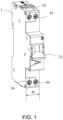
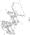
- FIGS. 1-7 show a miniature circuit breaker according to embodiments of the present invention.
- the miniature circuit breaker accommodates an operating mechanism, two-phase (1P+N) circuits, and corresponding opening and closing actuating mechanisms, controller, current detection device, etc. in an interior space defined by a single housing 1.
- the width H of the miniature circuit breaker module is defined as: H ⁇ 18 millimeters (i.e., less than or equal to 1 modulus), thereby achieving a simple structure and greatly reducing the volume.
- the miniature circuit breaker has only four wiring terminals, thereby optimizing wire connection operations and ensuring safety.
- the housing 1 consists of two opposite half housings, i.e., a first half housing 11 and a second half housing 12 that are detachably connected, and an intermediate casing 13 between the two opposite half housings.
- the first half housing 11, the second half housing 12, and the intermediate casing 13 collectively surround and define the interior space of the housing 1, and the intermediate casing 13 divides the interior space into two compartments for respective arrangement of the two-phase circuits.
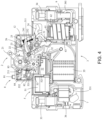
- FIG. 4 is a schematic view viewed from a first phase (e.g., P phase) circuit
- FIG. 5 is a schematic view viewed from a second phase (e.g., N phase) circuit
- the two circuits are respectively located in the compartments separated by the intermediate casing 13.
- the miniature circuit breaker includes an operating mechanism 2, a first phase circuit 3, a second phase circuit 4, a closing actuating mechanism 5, an opening actuating mechanism 6, and a control circuit board 7.
- the operating mechanism 2 includes a handle 21, and a latch 23 and a trip bar 24 operable with the handle 21. Referring to FIGS.
- the handle 21 has an orifice 213 through which a shaft rod connected to the housing 1 passes, whereby the handle 21 is rotatable about the shaft rod. A portion of the handle 21 extends out of the housing 1 for manual opening and closing operations.
- a handle torsional spring 212 is arranged between the handle 21 and the housing 1. The handle torsional spring 212 constantly applies, to the handle 21, a force that makes the handle rotate in a first direction (the clockwise direction in FIG. 4 , and the counterclockwise direction in FIG. 5 ) or have a tendency to rotate in the first direction. Once the handle 21 rotates in the first direction, it means that the miniature circuit breaker is opened.
- the handle 21 is connected to the latch 23 by mean of a connecting rod 22, the latch 23 is rotatably connected to a contact support frame 25 by mean of a connecting pin 254, and the contact support frame 25 is rotatably connected to a pivoting shaft 122 of the housing 1.
- a contact support frame spring 251 is arranged between the contact support frame 25 and a support wall 121 formed on the second half housing 12 of the housing 1.
- the contact support frame spring 251 constantly applies, to the contact support frame 25, a force that makes the contact support frame rotate in a second direction (the counterclockwise direction in FIG. 4 , and the clockwise direction in FIG. 5 ) or have a tendency to rotate in the second direction. Once the contact support frame 25 rotates in the second direction, it means that the miniature circuit breaker is opened.
- the trip bar 24 is pivotally connected to the contact support frame 25.
- a pivoting axis of the trip bar 24 coincides with a pivoting axis of the contact support frame 25.
- the trip bar 24 is constantly locked together with the latch 23.
- a trip bar torsional spring 241 is connected between the contact support frame 25 and the trip bar 24, and constantly applies, to the trip bar 24, a force that makes the trip bar rotate in the first direction (the clockwise direction in FIG.
- the trip bar 24 unlocked from the latch 23 can be reset and relocked (re-fastened) with the latch 23.
- the operating mechanism 2 is provided with an indicator plate 26.
- the indicator plate 26 is rotatably connected to the shaft rod arranged at the housing 1, and an arc-shaped slot 261 is formed on the body of the indicator plate 26.
- the connecting pin 254 for connecting the latch 23 to the contact support frame 25 passes through the arc-shaped slot 261 and is movable in the arc-shaped slot 261. Therefore, during opening and closing of the miniature circuit breaker, the indicator plate 26 is rotated such that different parts thereof are aligned with an opening formed on the housing 1.
- the different parts can be marked with "open", "on”, “close”, “off”, or other characters, or marked with different colors, such as blue and red, so as to transmit opening and closing status information to the outside.
- the closing actuating mechanism 5 that drives the action of the operating mechanism 2 is mounted in the interior space of the housing 1.
- the intermediate casing 13 is provided with a recess 133, and the closing actuating mechanism 5 is mounted in the recess 133.
- the closing actuating mechanism 5 is selected from electromagnetic closing mechanisms, and includes a closing coil 51 arranged in the recess and a closing armature 52 surrounded by the closing coil 51.
- the closing armature 52 is connected to and drives the handle 21 by means of a transmission mechanism, and the closing coil 51 is electrically connected to the control circuit board 7 mounted on the second half housing 12.
- the control circuit board 7 supplies power to the closing coil 51, so as to drive the closing armature 52 to move, e.g., retract into the closing coil 51, thereby driving the handle 21 to move.
- the closing armature 52 is connected to the handle 21 by means of a gear rack transmission mechanism.
- a rack 521 is mounted on the closing armature 52
- the handle 21 has a tooth structure 211 arranged along the circumference thereof
- a transmission gear 53 is arranged between the rack 521 and the tooth structure 211.
- the movement of the closing armature 52 drives, by means of the gear rack transmission mechanism, the handle 21 to rotate in the second direction, and the rotation of the handle 21 drives, by means of the connecting rod 22, the latch 23, the trip bar 24, and the contact support frame 25 to rotate together.
- the contact support frame 25 rotates in the first direction, thereby driving, by means of a first movable contact torsional spring 311, closing of a first movable contact 31 and a first stationary contact 32, and driving, by means of a second movable contact torsional spring 411, closing of a second movable contact 41 and a second stationary contact 42.
- the transmission gear 53 may be composed of two gears connected together and having different numbers of teeth, i.e., a first gear 531 engaging with the rack 521 and a second gear 532 engaging with the tooth structure of the handle 21.
- the two-gear structure can reduce a driving force required by the closing actuating mechanism during automatic closing, thereby reducing power consumption of the closing coil.
- the first phase circuit 3 may also be referred to as a P phase, and includes the first movable contact 31, the first stationary contact 32, a first wiring terminal 33, and a second wiring terminal 34.
- the first wiring terminal 33 is electrically connected to the first stationary contact 32 by means of a wire 331 to form a primary circuit.
- a first current transformer 36 is sleeved on the wire 331 and is located between the first wiring terminal 33 and the first stationary contact 32.
- the first current transformer 36 is electrically connected to the control circuit board 7 located in the interior space of the housing 1, thereby sending measured current information of the primary circuit to the control circuit board 7.
- the control circuit board 7 is mounted on the second half housing 12 and located between the second half housing 12 and the intermediate casing 13, and the intermediate casing 13 may be provided with a clearance opening to facilitate mounting of the first current transformer 36.
- the intermediate casing 13 may consist of a first casing portion 131 and a second casing portion 132 that are detachably provided, and the first casing portion 131 and the second casing portion 132 surround and define the clearance opening and the recess 133.
- the first movable contact 31 is pivotally connected to the contact support frame 25, and the first movable contact torsional spring 311 is connected between the contact support frame 25 and the first movable contact 31.
- the first movable contact torsional spring 311 applies, to the first movable contact 31, a force that makes the first movable contact rotate in the first direction (the clockwise direction in FIG. 4 , and the counterclockwise direction in FIG. 5 ) or have a tendency to rotate in the first direction.
- the first movable contact 31 approaches and is connected to the first stationary contact 32 to achieve closing of the first phase circuit 3.
- the opening actuating mechanism 6 is arranged between the first movable contact 31 and the second wiring terminal 34.
- the opening actuating mechanism 6 has a dual protection function, i.e., overload protection and short circuit protection.
- the opening actuating mechanism 6 employs an electromagnetic trip mechanism, wherein a first opening coil 62 for overload protection surrounds an opening armature 61, the first opening coil 62 is electrically connected to the control circuit board 7, a second opening coil 63 for short-circuit protection surrounds the first opening coil 62, and the second opening coil 63 is electrically connected to the second wiring terminal 34 by means of the wire 341.
- the control circuit board 7 supplies power to the first opening coil 62, driving the opening armature 61 to move towards the trip bar 24 and apply an impact on the trip bar 24, making the trip bar 24 unlocked from the latch 23, and thus allowing opening of the first movable contact 31 and the first stationary contact 32.
- a current flowing in the second opening coil 63 electrically connected to the second wiring terminal 34 makes the second opening coil 63 generate a magnetic field sufficient to drive the opening armature 61, such that the opening armature 61 moves and applies an impact on the trip bar 24, making the trip bar 24 unlocked from the latch 23, and thus allowing opening of the first movable contact 31 and the first stationary contact 32.
- two overload current thresholds or threshold ranges are preset, wherein the first threshold or threshold range is less than the second threshold or threshold range.
- an overload current detected by the first current transformer 36 is less than or equal to the first threshold or within the first threshold range, it means that the overload current is relatively small, in which case the power supply from the control circuit board 7 to the first opening coil 62 can be delayed for a preset time to realize a delayed opening function.
- an overload current detected by the first current transformer 36 is equal to or greater than the first threshold or within the second threshold range, it means that the overload current is relatively large, in which case power can be supplied from the control circuit board 7 to the first opening coil 62 almost immediately to realize a short-time fast opening function.
- remote operation opening may be achieved by means of the first opening coil 62 and the opening armature 61 connected to the control circuit board 7.
- the second phase circuit 4 includes a third wiring terminal 43, the second stationary contact 42 electrically connected to the third wiring terminal 43, the second movable contact 41, and a fourth wiring terminal 44 electrically connected to the second movable contact 41 by means of a wire 441. Similar to the first movable contact, the second movable contact 41 is pivotally connected to the contact support frame 25, and the first movable contact and second movable contact are located on two opposite sides of the contact support frame, respectively.
- the second movable contact torsional spring 411 is connected between the second movable contact 41 and the contact support frame 25 and constantly applies, to the second movable contact 41, a force that makes the second movable contact rotate in the first direction (the clockwise direction in FIG. 4 , and the counterclockwise direction in FIG. 5 ) or have a tendency to rotate in the first direction.
- the second movable contact 41 approaches and is connected to the second stationary contact 42 to achieve closing of the second phase circuit 4.
- the opening of the first phase circuit 3 and the opening of second phase circuit 4 are asynchronous, and by making the overtravel of the first movable contact 31 less than the overtravel of the second movable contact 41, the opening of the first movable contact 31 and the first stationary contact 32 may occur prior to the opening of the second movable contact 41 to the second stationary contact 42.
- the overtravel of the first movable contact 31 being less than the overtravel of the second movable contact 41 may be achieved by reasonably designing cooperation relationships between the contact support frame 25 with respect to the first movable contact 31 and second movable contact 41.
- the contact support frame 25 is provided with a first pin 252 on a side face where the first movable contact 31 is mounted and a second pin 253 on a side face where the second movable contact 41 is mounted, and an outer diameter of the first pin 252 is greater than an outer diameter of the second pin 253. Pivoting axes of the first movable contact 31 and the second movable contact 41 coincide.
- the first movable contact 31 has a first arc-shaped segment 312 extending along an outer circumferential surface of the first pin 252
- the second movable contact 41 has a second arc-shaped segment 412 extending along an outer circumferential surface of the second pin 253
- the arc angle of the first arc-shaped segment 312 is substantially the same as the arc angle of the second arc-shaped segment 412.
- the overtravel of the first movable contact 31 is less than the overtravel of the second movable contact 41, thereby enabling the opening of the first movable contact 31 and the first stationary contact 32 to occur prior to the opening of the second movable contact 41 and the second stationary contact 42.
- the overtravel of the first movable contact 31 being less than the overtravel of the second movable contact 41 can be achieved by a design in which the force applied by the first movable contact torsional spring 311 to the first movable contact 31 is different from the force applied by the second movable contact torsional spring 411 to the second movable contact 41.
- an arc extinguishing chamber 35 may be arranged for the first phase circuit 3 only. As shown in FIG. 4 , the arc extinguishing chamber 35 is arranged directly below the first stationary contact 32. Blocking plates (not shown) extending to the arc extinguishing chamber may be arranged at two opposite sides of the first stationary contact 32, ensuring that an arc is directed towards the arc extinguishing chamber 35.
- the first phase circuit 3 and the second phase circuit 4 are provided with a second current transformer 9 for leakage protection.
- the wire 341 connecting the second wiring terminal 34 and the opening actuating mechanism 6 and the wire 441 connecting the fourth wiring terminal 44 and the second movable contact 41 both pass through the second current transformer 9.
- the second current transformer 9 is electrically connected to the control circuit board 7 to send a signal to the control circuit board 7 upon detection of a leakage current, and based on the signal, the control circuit board 7 controls the opening actuating mechanism 6 to drive the trip bar 24 to trip.
- the miniature circuit breaker according to this embodiment is further provided with a test assembly 8 for leakage tests.
- a button 81 of the test assembly 8 is inserted in an opening of the housing 1 and is movable relative to the housing 1, and a conductive structure electrically connected to the fourth wiring terminal 44 is provided on a side of the button 81 facing the housing 1.
- a wire 82 extends in the interior space of the housing 1 and is electrically connected to the control circuit board 7. Moreover, the wire 82 is electrically connected to the wire 331/first wiring terminal 33.
- a resistor 84 is provided at an end portion of the wire 82 facing the button 81, and the resistor 84 is in the interior space of the housing 1, and is spaced apart from the button 81 and the conductive mechanism by a specific distance under normal conditions.
- the button 81 drives the conductive mechanism to form a short circuit connection with the resistor 84 and the wire 82, and a leakage current would be generated since the conductive mechanism is electrically connected to the fourth wiring terminal 44 by means of a wire.
- control circuit board 7 When the control circuit board 7 detects a leakage signal, the control circuit board 7 supplies power the first opening coil 62, driving the opening armature 61 to move towards the trip bar 24 and apply an impact on the trip bar 24, making the trip bar 24 unlocked from the latch 23, allowing the opening of the first movable contact 31 and the first stationary contact 32, and thereby completing the leakage test.
- an elastic member 83 (e.g., a torsional spring) is arranged on the housing 1 and supports the button 81.
- the elastic member 83 constantly applies, to the button 81, a force that makes the button move in a direction away from the housing 1 or have a tendency to move in the direction away from the housing 1. In this way, only when the button 81 is pressed toward the interior of the housing 1 can the button 81 drive the conductive structure to form a short circuit connection with the resistor 84 and conduct the circuit. Once the pressing force is withdrawn, the button 81 immediately moves away from the resistor under the action of the elastic member 83, thus switching off the circuit.
- the function of the conductive structure is achieved by electrically connecting the elastic member 83 to the fourth wiring terminal 44 by means of a wire.
- each embodiment does not necessarily include only one independent technical solution.
- the presentation manner of the description is merely for clearness, and those skilled in the art should regard the description as a whole, and the technical solutions in the embodiments can also be appropriately combined to form other implementations comprehensible by those skilled in the art.
Landscapes
- Physics & Mathematics (AREA)
- Electromagnetism (AREA)
- Engineering & Computer Science (AREA)
- Power Engineering (AREA)
- Breakers (AREA)
Claims (10)
- Leitungsschutzschalter, der Folgendes umfasst:ein Gehäuse (1), das einen Innenraum definiert;eine Steuerleiterplatte (7), die im Innenraum angeordnet ist;einen Betätigungsmechanismus (2), der einen Griff (21), eine Rastklinke (23), die mit dem Griff (21) verbunden ist, eine Auslösestange (24), die mit der Rastklinke (23) verriegelt oder davon entriegelt werden kann, und einen Kontaktträgerrahmen (25), der die Rastklinke (23) und die Auslösestange (24) trägt, umfasst;eine erste Phasenschaltung (3), die einen ersten Verdrahtungsanschluss (33), einen ersten feststehenden Kontakt (31), der mit dem ersten Verdrahtungsanschluss (33) elektrisch verbunden ist, einen ersten beweglichen Kontakt (31), der mit dem Kontaktträgerrahmen (25) drehbar verbunden ist, und einen zweiten Verdrahtungsanschluss (34) umfasst;eine zweite Phasenschaltung (4), die einen dritten Verdrahtungsanschluss (43), einen zweiten feststehenden Kontakt (42), der mit dem dritten Verdrahtungsanschluss (43) elektrisch verbunden ist, einen zweiten beweglichen Kontakt (41), der mit dem Kontaktträgerrahmen (25) drehbar verbunden ist, und einen vierten Verdrahtungsanschluss (44), der mit dem zweiten beweglichen Kontakt (41) elektrisch verbunden ist, umfasst;einen Schließbetätigungsmechanismus (5), der mit der Steuerleiterplatte (7) elektrisch verbunden ist und mit dem Betätigungsmechanismus (2) verbunden ist und diesen antreibt;eine erste Stromdetektionsvorrichtung, die konfiguriert ist, einen Strom, der durch den ersten feststehenden Kontakt (32) fließt, zu detektieren, und mit der Steuerleiterplatte (7) elektrisch verbunden ist;eine zweite Stromdetektionsvorrichtung, die konfiguriert ist, einen Strom, der durch den zweiten Verdrahtungsanschluss (34) und den vierten Verdrahtungsanschluss (44) fließt, zu detektieren und mit der Steuerleitungsplatte (7) elektrisch verbunden ist; undeinen Öffnungsbetätigungsmechanismus (6), der mit dem zweiten Verdrahtungsanschluss (34) und der Steuerleiterplatte (7) elektrisch verbunden ist und konfiguriert ist, basierend auf Strominformationen, die durch die erste Stromdetektionsvorrichtung und die zweite Stromdetektionsvorrichtung detektiert werden, wahlweise die Auslösestange (24) derart anzutreiben, dass sie von der Rastklinke (23) entriegelt wird.
- Leitungsschutzschalter nach Anspruch 1, wobei der erste Verdrahtungsanschluss (33) mittels eines Drahtes (331) mit dem ersten feststehenden Kontakt (32) verbunden ist und die erste Stromdetektionsvorrichtung ein erster Stromwandler (36) ist, der auf den Draht (331) umhüllend aufgeschoben ist.
- Leitungsschutzschalter nach Anspruch 1, wobei der zweite Verdrahtungsanschluss (34) mittels eines Drahtes (341) mit dem Öffnungsbetätigungsmechanismus (6) verbunden ist, der vierte Verdrahtungsanschluss (44) mittels eines Drahtes (441) mit dem zweiten beweglichen Kontakt (41) verbunden ist und die zweite Stromdetektionsvorrichtung ein zweiter Stromwandler (9) ist, der auf die zwei Drähte (341, 441) umhüllend aufgeschoben ist.
- Leitungsschutzschalter nach Anspruch 1, wobei der Öffnungsbetätigungsmechanismus (6) Folgendes umfasst:einen Öffnungsanker (61), der im Innenraum des Gehäuses (1) beweglich angebracht ist; undeine erste Öffnungsspule (62), die den Öffnungsanker (61) umgibt und mit der Steuerleiterplatte (7) elektrisch verbunden ist;wobei die Steuerleiterplatte (7) konfiguriert ist, den Öffnungsanker (61) auf der Grundlage der Stromzustände, die durch die erste Stromdetektionsvorrichtung und/oder die zweite Stromdetektionsvorrichtung detektiert werden, derart zu steuern, dass er sich bewegt, um die Auslösestange (24) derart anzutreiben, dass sie von der Rastklinke (23) entriegelt wird.
- Leitungsschutzschalter nach Anspruch 1, wobei der Öffnungsbetätigungsmechanismus (6) Folgendes umfasst:einen Öffnungsanker (61), der im Innenraum des Gehäuses (1) beweglich angebracht ist; undeine zweite Öffnungsspule (63), die den Öffnungsanker (61) umgibt und mit dem zweiten Verdrahtungsanschluss (34) elektrisch verbunden ist, wobei die zweite Öffnungsspule (63) den Öffnungsanker (61) auf der Grundlage der Stromzustände derart antreibt, dass er sich bewegt, um die Auslösestange (24) derart anzutreiben, dass sie von der Rastklinke (23) entriegelt wird.
- Leitungsschutzschalter nach Anspruch 1, wobei das Gehäuse (1) ein erstes Halbgehäuse (11) und ein zweites Halbgehäuse (12), die einander gegenüberliegend angeordnet sind, und ein Zwischengehäuse (13), das zwischen dem ersten Halbgehäuse (11) und dem zweiten Halbgehäuse (12) angeordnet ist, umfasst und der Schließbetätigungsmechanismus (5) durch das Zwischengehäuse (13) getragen wird und Folgendes umfasst:eine Schließspule (51), die am Zwischengehäuse (13) angeordnet ist; undeinen Schließanker (52), der durch die Schließspule (51) beweglich verläuft und mit dem Griff (21) verbunden ist und diesen antreibt.
- Leitungsschutzschalter nach Anspruch 6, wobei die Steuerleiterplatte (7) an einem Ort, der zum ersten Verdrahtungsanschluss (33) und zur ersten Stromdetektionsvorrichtung benachbart ist, am Zwischengehäuse (13) arretiert ist und eine Abstandsöffnung, die der ersten Stromdetektionsvorrichtung entspricht, im Zwischengehäuse (13) gebildet ist.
- Leitungsschutzschalter nach Anspruch 1, wobei der Kontaktträgerrahmen (25) auf dem Gehäuse (1) drehbar angebracht ist und der erste bewegliche Kontakt (31) und der zweite bewegliche Kontakt (41) auf dem Kontaktträgerrahmen (25) drehbar angebracht sind, wobei ein Überlauf des ersten beweglichen Kontakts (31) kleiner als ein Überlauf des zweiten beweglichen Kontakts (41) ist und eine Lichtbogen-Löschkammer (35), die dem ersten feststehenden Kontakt (32) entspricht, im Innenraum angeordnet ist.
- Leitungsschutzschalter nach Anspruch 1, wobei der Betätigungsmechanismus (2) ferner eine Indikatorplatte (26) umfasst, die auf dem Gehäuse (1) drehbar angebracht ist, wobei die Indikatorplatte (26) einen bogenförmigen Schlitz (261) aufweist und ein Verbindungsstift (254), der die Rastklinke (23) mit dem Kontaktträgerrahmen (25) drehbar verbindet, im bogenförmigen Schlitz (261) eingesetzt ist und im bogenförmigen Schlitz (261) beweglich ist.
- Leitungsschutzschalter nach Anspruch 1, der ferner eine Prüfanordnung (8) umfasst, wobei die Prüfanordnung (8) Folgendes umfasst:einen Knopf (81), der am Gehäuse (1) beweglich angebracht ist; undeine leitfähige Struktur, die auf dem Knopf (81) vorgesehen ist und mit dem vierten Verdrahtungsanschluss (44) elektrisch verbunden ist; und einen Widerstand (84), der mit der Steuerleiterplatte (7) und dem ersten Verdrahtungsanschluss (33) elektrisch verbunden ist;wobei dann, wenn sich der Knopf (81) in Richtung des Gehäuses (1) bewegt, die leitfähige Struktur mit dem Widerstand (84) elektrisch verbunden werden kann.
Applications Claiming Priority (1)
| Application Number | Priority Date | Filing Date | Title |
|---|---|---|---|
| CN202210167178.XA CN116682702A (zh) | 2022-02-23 | 2022-02-23 | 微型断路器 |
Publications (2)
| Publication Number | Publication Date |
|---|---|
| EP4235728A1 EP4235728A1 (de) | 2023-08-30 |
| EP4235728B1 true EP4235728B1 (de) | 2024-11-20 |
Family
ID=85380945
Family Applications (1)
| Application Number | Title | Priority Date | Filing Date |
|---|---|---|---|
| EP23158269.3A Active EP4235728B1 (de) | 2022-02-23 | 2023-02-23 | Schutzschalter |
Country Status (2)
| Country | Link |
|---|---|
| EP (1) | EP4235728B1 (de) |
| CN (1) | CN116682702A (de) |
Families Citing this family (1)
| Publication number | Priority date | Publication date | Assignee | Title |
|---|---|---|---|---|
| CN118116777B (zh) * | 2024-03-05 | 2024-09-03 | 浙江东亚电子有限公司 | 一种紧凑型高密度智能断路器 |
Family Cites Families (1)
| Publication number | Priority date | Publication date | Assignee | Title |
|---|---|---|---|---|
| KR100718530B1 (ko) * | 2006-04-29 | 2007-05-18 | 이한식 | 자동복귀수단을 구비한 누전차단기 |
-
2022
- 2022-02-23 CN CN202210167178.XA patent/CN116682702A/zh active Pending
-
2023
- 2023-02-23 EP EP23158269.3A patent/EP4235728B1/de active Active
Also Published As
| Publication number | Publication date |
|---|---|
| EP4235728A1 (de) | 2023-08-30 |
| CN116682702A (zh) | 2023-09-01 |
Similar Documents
| Publication | Publication Date | Title |
|---|---|---|
| EP4235729A1 (de) | Öffnungs- und schliessmechanismus und miniaturschutzschalter | |
| EP2180487B1 (de) | Mikroschalter | |
| US5231365A (en) | Circuit breaker | |
| CN113035661B (zh) | 漏电断路器 | |
| US6215378B1 (en) | Circuit breaker with dual function test button remote from test circuit | |
| KR20080059503A (ko) | 누전 차단기 | |
| EP4235728B1 (de) | Schutzschalter | |
| JPS63105426A (ja) | 交換可能なスイッチを有する電磁スイッチ装置 | |
| EP1814133B1 (de) | Schaltvorrichtung | |
| US7227279B2 (en) | Phase deficiency display device for thermal magnetic type molded case circuit breaker | |
| EP2015339B1 (de) | Auslöseeinheitsmodul und Schutzschalter damit | |
| JP4906517B2 (ja) | 漏電遮断器 | |
| JP4507944B2 (ja) | 漏電遮断器 | |
| KR20180099329A (ko) | 누전차단기의 누전 표시 장치 | |
| CN215527637U (zh) | 一种断路器 | |
| JP2007149528A (ja) | 回路遮断器 | |
| JP3849344B2 (ja) | 回路遮断器 | |
| JP2006155912A (ja) | リモートコントロール式漏電遮断器 | |
| CN213277974U (zh) | 用于断路器的脱扣报警附件及具有其的断路器 | |
| CN119049938B (zh) | 一种断路器装置 | |
| CN215527636U (zh) | 一种断路器通断指示装置及断路器 | |
| EP1724804B1 (de) | Rückstellmodul für elektrische Schutzvorrichtung | |
| CN222867579U (zh) | 电气装置 | |
| JP4144589B2 (ja) | リモートコントロール式漏電遮断器 | |
| JP4144588B2 (ja) | リモートコントロール式漏電遮断器 |
Legal Events
| Date | Code | Title | Description |
|---|---|---|---|
| PUAI | Public reference made under article 153(3) epc to a published international application that has entered the european phase |
Free format text: ORIGINAL CODE: 0009012 |
|
| STAA | Information on the status of an ep patent application or granted ep patent |
Free format text: STATUS: THE APPLICATION HAS BEEN PUBLISHED |
|
| AK | Designated contracting states |
Kind code of ref document: A1 Designated state(s): AL AT BE BG CH CY CZ DE DK EE ES FI FR GB GR HR HU IE IS IT LI LT LU LV MC ME MK MT NL NO PL PT RO RS SE SI SK SM TR |
|
| STAA | Information on the status of an ep patent application or granted ep patent |
Free format text: STATUS: REQUEST FOR EXAMINATION WAS MADE |
|
| 17P | Request for examination filed |
Effective date: 20240102 |
|
| RBV | Designated contracting states (corrected) |
Designated state(s): AL AT BE BG CH CY CZ DE DK EE ES FI FR GB GR HR HU IE IS IT LI LT LU LV MC ME MK MT NL NO PL PT RO RS SE SI SK SM TR |
|
| GRAP | Despatch of communication of intention to grant a patent |
Free format text: ORIGINAL CODE: EPIDOSNIGR1 |
|
| GRAP | Despatch of communication of intention to grant a patent |
Free format text: ORIGINAL CODE: EPIDOSNIGR1 |
|
| STAA | Information on the status of an ep patent application or granted ep patent |
Free format text: STATUS: GRANT OF PATENT IS INTENDED |
|
| INTG | Intention to grant announced |
Effective date: 20240614 |
|
| RIN1 | Information on inventor provided before grant (corrected) |
Inventor name: WANG, ZHENGZHONG Inventor name: HU, ZHENGNING Inventor name: ZHOU, HUI Inventor name: GUO, SHUNFENG |
|
| GRAS | Grant fee paid |
Free format text: ORIGINAL CODE: EPIDOSNIGR3 |
|
| GRAA | (expected) grant |
Free format text: ORIGINAL CODE: 0009210 |
|
| STAA | Information on the status of an ep patent application or granted ep patent |
Free format text: STATUS: THE PATENT HAS BEEN GRANTED |
|
| AK | Designated contracting states |
Kind code of ref document: B1 Designated state(s): AL AT BE BG CH CY CZ DE DK EE ES FI FR GB GR HR HU IE IS IT LI LT LU LV MC ME MK MT NL NO PL PT RO RS SE SI SK SM TR |
|
| REG | Reference to a national code |
Ref country code: GB Ref legal event code: FG4D |
|
| REG | Reference to a national code |
Ref country code: CH Ref legal event code: EP |
|
| REG | Reference to a national code |
Ref country code: DE Ref legal event code: R096 Ref document number: 602023001048 Country of ref document: DE |
|
| REG | Reference to a national code |
Ref country code: IE Ref legal event code: FG4D |
|
| P01 | Opt-out of the competence of the unified patent court (upc) registered |
Free format text: CASE NUMBER: APP_94/2025 Effective date: 20250102 |
|
| REG | Reference to a national code |
Ref country code: LT Ref legal event code: MG9D |
|
| REG | Reference to a national code |
Ref country code: NL Ref legal event code: MP Effective date: 20241120 |
|
| PG25 | Lapsed in a contracting state [announced via postgrant information from national office to epo] |
Ref country code: IS Free format text: LAPSE BECAUSE OF FAILURE TO SUBMIT A TRANSLATION OF THE DESCRIPTION OR TO PAY THE FEE WITHIN THE PRESCRIBED TIME-LIMIT Effective date: 20250320 Ref country code: HR Free format text: LAPSE BECAUSE OF FAILURE TO SUBMIT A TRANSLATION OF THE DESCRIPTION OR TO PAY THE FEE WITHIN THE PRESCRIBED TIME-LIMIT Effective date: 20241120 Ref country code: PT Free format text: LAPSE BECAUSE OF FAILURE TO SUBMIT A TRANSLATION OF THE DESCRIPTION OR TO PAY THE FEE WITHIN THE PRESCRIBED TIME-LIMIT Effective date: 20250320 |
|
| PG25 | Lapsed in a contracting state [announced via postgrant information from national office to epo] |
Ref country code: FI Free format text: LAPSE BECAUSE OF FAILURE TO SUBMIT A TRANSLATION OF THE DESCRIPTION OR TO PAY THE FEE WITHIN THE PRESCRIBED TIME-LIMIT Effective date: 20241120 Ref country code: NL Free format text: LAPSE BECAUSE OF FAILURE TO SUBMIT A TRANSLATION OF THE DESCRIPTION OR TO PAY THE FEE WITHIN THE PRESCRIBED TIME-LIMIT Effective date: 20241120 |
|
| REG | Reference to a national code |
Ref country code: AT Ref legal event code: MK05 Ref document number: 1744376 Country of ref document: AT Kind code of ref document: T Effective date: 20241120 |
|
| PG25 | Lapsed in a contracting state [announced via postgrant information from national office to epo] |
Ref country code: BG Free format text: LAPSE BECAUSE OF FAILURE TO SUBMIT A TRANSLATION OF THE DESCRIPTION OR TO PAY THE FEE WITHIN THE PRESCRIBED TIME-LIMIT Effective date: 20241120 |
|
| PG25 | Lapsed in a contracting state [announced via postgrant information from national office to epo] |
Ref country code: ES Free format text: LAPSE BECAUSE OF FAILURE TO SUBMIT A TRANSLATION OF THE DESCRIPTION OR TO PAY THE FEE WITHIN THE PRESCRIBED TIME-LIMIT Effective date: 20241120 |
|
| PG25 | Lapsed in a contracting state [announced via postgrant information from national office to epo] |
Ref country code: NO Free format text: LAPSE BECAUSE OF FAILURE TO SUBMIT A TRANSLATION OF THE DESCRIPTION OR TO PAY THE FEE WITHIN THE PRESCRIBED TIME-LIMIT Effective date: 20250220 |
|
| PG25 | Lapsed in a contracting state [announced via postgrant information from national office to epo] |
Ref country code: LV Free format text: LAPSE BECAUSE OF FAILURE TO SUBMIT A TRANSLATION OF THE DESCRIPTION OR TO PAY THE FEE WITHIN THE PRESCRIBED TIME-LIMIT Effective date: 20241120 Ref country code: GR Free format text: LAPSE BECAUSE OF FAILURE TO SUBMIT A TRANSLATION OF THE DESCRIPTION OR TO PAY THE FEE WITHIN THE PRESCRIBED TIME-LIMIT Effective date: 20250221 Ref country code: AT Free format text: LAPSE BECAUSE OF FAILURE TO SUBMIT A TRANSLATION OF THE DESCRIPTION OR TO PAY THE FEE WITHIN THE PRESCRIBED TIME-LIMIT Effective date: 20241120 |
|
| PG25 | Lapsed in a contracting state [announced via postgrant information from national office to epo] |
Ref country code: PL Free format text: LAPSE BECAUSE OF FAILURE TO SUBMIT A TRANSLATION OF THE DESCRIPTION OR TO PAY THE FEE WITHIN THE PRESCRIBED TIME-LIMIT Effective date: 20241120 |
|
| PG25 | Lapsed in a contracting state [announced via postgrant information from national office to epo] |
Ref country code: RS Free format text: LAPSE BECAUSE OF FAILURE TO SUBMIT A TRANSLATION OF THE DESCRIPTION OR TO PAY THE FEE WITHIN THE PRESCRIBED TIME-LIMIT Effective date: 20250220 |
|
| PG25 | Lapsed in a contracting state [announced via postgrant information from national office to epo] |
Ref country code: SM Free format text: LAPSE BECAUSE OF FAILURE TO SUBMIT A TRANSLATION OF THE DESCRIPTION OR TO PAY THE FEE WITHIN THE PRESCRIBED TIME-LIMIT Effective date: 20241120 |
|
| PG25 | Lapsed in a contracting state [announced via postgrant information from national office to epo] |
Ref country code: DK Free format text: LAPSE BECAUSE OF FAILURE TO SUBMIT A TRANSLATION OF THE DESCRIPTION OR TO PAY THE FEE WITHIN THE PRESCRIBED TIME-LIMIT Effective date: 20241120 |
|
| PG25 | Lapsed in a contracting state [announced via postgrant information from national office to epo] |
Ref country code: EE Free format text: LAPSE BECAUSE OF FAILURE TO SUBMIT A TRANSLATION OF THE DESCRIPTION OR TO PAY THE FEE WITHIN THE PRESCRIBED TIME-LIMIT Effective date: 20241120 |
|
| PG25 | Lapsed in a contracting state [announced via postgrant information from national office to epo] |
Ref country code: RO Free format text: LAPSE BECAUSE OF FAILURE TO SUBMIT A TRANSLATION OF THE DESCRIPTION OR TO PAY THE FEE WITHIN THE PRESCRIBED TIME-LIMIT Effective date: 20241120 |
|
| PG25 | Lapsed in a contracting state [announced via postgrant information from national office to epo] |
Ref country code: SK Free format text: LAPSE BECAUSE OF FAILURE TO SUBMIT A TRANSLATION OF THE DESCRIPTION OR TO PAY THE FEE WITHIN THE PRESCRIBED TIME-LIMIT Effective date: 20241120 |
|
| REG | Reference to a national code |
Ref country code: DE Ref legal event code: R097 Ref document number: 602023001048 Country of ref document: DE |
|
| PG25 | Lapsed in a contracting state [announced via postgrant information from national office to epo] |
Ref country code: SE Free format text: LAPSE BECAUSE OF FAILURE TO SUBMIT A TRANSLATION OF THE DESCRIPTION OR TO PAY THE FEE WITHIN THE PRESCRIBED TIME-LIMIT Effective date: 20241120 |
|
| PG25 | Lapsed in a contracting state [announced via postgrant information from national office to epo] |
Ref country code: MC Free format text: LAPSE BECAUSE OF FAILURE TO SUBMIT A TRANSLATION OF THE DESCRIPTION OR TO PAY THE FEE WITHIN THE PRESCRIBED TIME-LIMIT Effective date: 20241120 |
|
| PLBE | No opposition filed within time limit |
Free format text: ORIGINAL CODE: 0009261 |
|
| STAA | Information on the status of an ep patent application or granted ep patent |
Free format text: STATUS: NO OPPOSITION FILED WITHIN TIME LIMIT |
|
| PG25 | Lapsed in a contracting state [announced via postgrant information from national office to epo] |
Ref country code: LU Free format text: LAPSE BECAUSE OF NON-PAYMENT OF DUE FEES Effective date: 20250223 |
|
| 26N | No opposition filed |
Effective date: 20250821 |
|
| REG | Reference to a national code |
Ref country code: BE Ref legal event code: MM Effective date: 20250228 |
|
| PG25 | Lapsed in a contracting state [announced via postgrant information from national office to epo] |
Ref country code: BE Free format text: LAPSE BECAUSE OF NON-PAYMENT OF DUE FEES Effective date: 20250228 |
|
| PG25 | Lapsed in a contracting state [announced via postgrant information from national office to epo] |
Ref country code: IE Free format text: LAPSE BECAUSE OF NON-PAYMENT OF DUE FEES Effective date: 20250223 |
|
| REG | Reference to a national code |
Ref country code: CH Ref legal event code: U11 Free format text: ST27 STATUS EVENT CODE: U-0-0-U10-U11 (AS PROVIDED BY THE NATIONAL OFFICE) Effective date: 20260301 |
|
| PGFP | Annual fee paid to national office [announced via postgrant information from national office to epo] |
Ref country code: DE Payment date: 20260121 Year of fee payment: 4 |
|
| PGFP | Annual fee paid to national office [announced via postgrant information from national office to epo] |
Ref country code: IT Payment date: 20260228 Year of fee payment: 4 |
|
| PGFP | Annual fee paid to national office [announced via postgrant information from national office to epo] |
Ref country code: FR Payment date: 20260121 Year of fee payment: 4 |
|
| PGFP | Annual fee paid to national office [announced via postgrant information from national office to epo] |
Ref country code: CH Payment date: 20260301 Year of fee payment: 4 Ref country code: CZ Payment date: 20260211 Year of fee payment: 4 |