EP4235571A2 - Verfahren zur bildregistrierung sowie vorrichtung - Google Patents
Verfahren zur bildregistrierung sowie vorrichtung Download PDFInfo
- Publication number
- EP4235571A2 EP4235571A2 EP23169492.8A EP23169492A EP4235571A2 EP 4235571 A2 EP4235571 A2 EP 4235571A2 EP 23169492 A EP23169492 A EP 23169492A EP 4235571 A2 EP4235571 A2 EP 4235571A2
- Authority
- EP
- European Patent Office
- Prior art keywords
- image
- pixel
- gradient
- correlation coefficient
- extreme
- Prior art date
- Legal status (The legal status is an assumption and is not a legal conclusion. Google has not performed a legal analysis and makes no representation as to the accuracy of the status listed.)
- Granted
Links
Images


Classifications
-
- G—PHYSICS
- G06—COMPUTING OR CALCULATING; COUNTING
- G06T—IMAGE DATA PROCESSING OR GENERATION, IN GENERAL
- G06T3/00—Geometric image transformations in the plane of the image
- G06T3/40—Scaling of whole images or parts thereof, e.g. expanding or contracting
- G06T3/4038—Image mosaicing, e.g. composing plane images from plane sub-images
-
- G—PHYSICS
- G06—COMPUTING OR CALCULATING; COUNTING
- G06T—IMAGE DATA PROCESSING OR GENERATION, IN GENERAL
- G06T7/00—Image analysis
- G06T7/30—Determination of transform parameters for the alignment of images, i.e. image registration
- G06T7/32—Determination of transform parameters for the alignment of images, i.e. image registration using correlation-based methods
-
- G—PHYSICS
- G06—COMPUTING OR CALCULATING; COUNTING
- G06T—IMAGE DATA PROCESSING OR GENERATION, IN GENERAL
- G06T3/00—Geometric image transformations in the plane of the image
- G06T3/14—Transformations for image registration, e.g. adjusting or mapping for alignment of images
-
- G—PHYSICS
- G06—COMPUTING OR CALCULATING; COUNTING
- G06T—IMAGE DATA PROCESSING OR GENERATION, IN GENERAL
- G06T7/00—Image analysis
- G06T7/0002—Inspection of images, e.g. flaw detection
-
- G—PHYSICS
- G06—COMPUTING OR CALCULATING; COUNTING
- G06T—IMAGE DATA PROCESSING OR GENERATION, IN GENERAL
- G06T7/00—Image analysis
- G06T7/10—Segmentation; Edge detection
- G06T7/11—Region-based segmentation
-
- G—PHYSICS
- G06—COMPUTING OR CALCULATING; COUNTING
- G06T—IMAGE DATA PROCESSING OR GENERATION, IN GENERAL
- G06T7/00—Image analysis
- G06T7/10—Segmentation; Edge detection
- G06T7/136—Segmentation; Edge detection involving thresholding
-
- G—PHYSICS
- G06—COMPUTING OR CALCULATING; COUNTING
- G06T—IMAGE DATA PROCESSING OR GENERATION, IN GENERAL
- G06T7/00—Image analysis
- G06T7/30—Determination of transform parameters for the alignment of images, i.e. image registration
- G06T7/33—Determination of transform parameters for the alignment of images, i.e. image registration using feature-based methods
- G06T7/337—Determination of transform parameters for the alignment of images, i.e. image registration using feature-based methods involving reference images or patches
-
- G—PHYSICS
- G06—COMPUTING OR CALCULATING; COUNTING
- G06T—IMAGE DATA PROCESSING OR GENERATION, IN GENERAL
- G06T2207/00—Indexing scheme for image analysis or image enhancement
- G06T2207/10—Image acquisition modality
- G06T2207/10056—Microscopic image
Definitions
- the present application is a divisional application of European Patent Application No. 18867368.5, which has a filing date of October 15, 2018 .
- the present invention relates to the field of image processing and, in particular, to an image registration method and apparatus, and an image stitching method and device.
- image registration and stitching operations are required.
- the registration operation the displacements of the floating image (or moving image, current image) relative to the reference image (previous image) in both the abscissa and ordinate directions can be obtained.
- the stitching operation stitches the floating image and the reference image into one image according to the registration result obtained by the registration operation.
- the traditional rigid body registration method uses an iterative method to optimize a cost function representing the difference between a reference image and a floating image to obtain a translation vector. Because iterative processes require a lot of calculations, they are not suitable for real-time applications.
- correlation coefficient method correlation coefficient method
- correlation coefficient method correlation coefficient method
- the correlation coefficient peak method There is a correlation coefficient between the floating image with any translation vector and the reference image.
- the correlation coefficient is the maximum. If the maximum value of the correlation coefficients corresponding to all possible translation vectors is found through search, then the appropriate displacement that can be used to register the floating image is determined accordingly.
- this method is only suitable for images reconstructed by the phase recovery method. In many application scenarios, such as field of view stitching applications, floating images will definitely have new content that is different from the reference image. This will bring great errors to the above correlation coefficient method.
- the moving speed of the probe of the microscope that captures the image is high, the difference between the content presented in the floating image and the reference image is relative large, and a wrong registration result which is completely different from the real displacement will be obtained.
- the present invention is proposed in consideration of the above problems.
- the present invention provides an image registration method and apparatus, and an image stitching method and device.
- an image registration method which includes:
- the determining a pixel with extreme correlation coefficient in the correlation coefficient image according to a pixel with extreme gradient in the gradient image includes:
- the finding the pixel with extreme correlation coefficient according to the corresponding pixel in the correlation coefficient image includes:
- the determining a pixel with extreme correlation coefficient in the correlation coefficient image according to a pixel with extreme gradient in the gradient image includes:
- the performing region segmentation on the gradient image according to the first gradient threshold includes:
- the performing region segmentation on the gradient image according to the seed pixels includes: performing region segmentation on the gradient image according to a region growing algorithm by taking the seed pixels as the starting point.
- the determining a first gradient threshold according to the pixel with maximum gradient includes:
- an image registration apparatus which includes:
- an image stitching method which includes:
- an image stitching device which includes:
- the above image registration method and apparatus have high universality, which can be applied to various images, rather than only the images reconstructed by using the phase recovery method.
- the image registration method and apparatus require a small amount of calculation, thereby ensuring real-time operation.
- the registration results obtained by the image registration method and apparatus are more accurate. Even if there are many new contents in the floating image compared with that of the reference image, the image registration method and apparatus can also obtain good registration results.
- the above image stitching method and device make use of the above image registration method and apparatus, thereby ensuring the real-time and accuracy of the stitching operation.
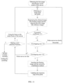
- FIG. 1 shows an image registration method 100 according to an embodiment of the present invention.
- the image registration method 100 is used to register a reference image and a floating image.
- the reference image can be used as a benchmark image, and the image registration method 100 is used to calculate the displacement of the floating image relative to the reference image.
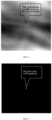
- FIG. 2A, FIG. 2B and FIG. 2C respectively show three images to be registered.
- FIG. 3 shows a resulting image of spatial registration, through two registration operations, and stitching of the images shown in FIG. 2A, FIG. 2B and FIG. 2C .
- the image shown in FIG. 2A is the reference image
- the image shown in FIG. 2B is the floating image.
- the image shown in FIG. 2C is the floating image.
- the reference image and the floating image can be a variety of images, especially images in the same mode, that is, images acquired by same image acquisition equipment, such as images from a same microscope.
- images from a same microscope are two-dimensional images, and the overlapping area of adjacent frames is relatively large, which makes the image registration method more accurate.
- step S120 a correlation coefficient image between a reference image and a floating image is calculated.
- the correlation coefficient image is essentially a digital matrix, where each element represents the correlation coefficient of the displacement between the reference image and the floating image corresponding to the element.
- the positional relation of adjacent pixels corresponds to a unit displacement in the positive or negative direction of the horizontal or vertical coordinates between the floating image and the reference image.
- the correlation coefficient image can be calculated by using the correlation coefficient method.
- the correlation coefficient image is four times the size of a reference image. For example, if both the reference image and the floating image are 100*200, the correlation coefficient image is 200*400.
- the correlation coefficients can be obtained through calculation including a conjugate multiplication of the Fourier transforms of the reference image and the floating image, and an inverse Fourier transform thereafter, and all possible correlation coefficients form a correlation coefficient image.
- r fg x i y i ⁇ u , v F u v G * u v exp i 2 ⁇ ux i M + vy i N , where r fg ( x i ,y i ) represents the pixel value at the position of ( x i ,y i )in the correlation coefficient image, F ( u v ) and G ( u v ) represents the Fourier transform of the reference image and the floating image respectively, and M and N represent the number of columns and rows of the reference image respectively.
- step S140 a gradient image of the correlation coefficient image is calculated. Similar to the correlation coefficient image, the gradient image is essentially a digital matrix, where each element represents a gradient of a corresponding position in the correlation coefficient image.
- the existing correlation coefficient method is usually used for the image reconstructed by using the phase recovery method.
- the correct displacement that can be used to register floating image is determined.
- the maximum correlation coefficient in the image does not appear at the real position, but at the edge of the image, which is very far away from the real registration position.
- FIG. 4 shows a correlation coefficient image obtained by using the images shown in FIG. 2A and FIG. 2C as the reference image and the floating image for image registration, respectively.
- the maximum correlation coefficient exists on the lower edge of the image.
- FIG. 5 shows a gradient image of the correlation coefficient image shown in FIG. 4 , which vividly illustrates the above problems.
- the gradient of the correlation coefficient is calculated according to the following formula.
- g i j r fg i ⁇ 1 , j ⁇ r fg i + 1 , j 2 + r fg i , j ⁇ 1 ⁇ r fg i , j + 1 2
- g ( i , j ) represents the pixel value at the position of ( i , j ) in the gradient image, that is, the gradient
- r f g ( i , j ) represents the pixel value at the position of ( i , j ) in the correlation coefficient image, that is, the correlation coefficient.
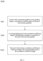
- step S160 a pixel with extreme correlation coefficient in the correlation coefficient image is determined according to a pixel with extreme gradient in the gradient image.
- the pixel corresponding to the pixel with extreme gradient is determined in the correlation coefficient image.
- the pixel with extreme gradient in the gradient image may not be perfectly corresponding to the pixel with extreme correlation coefficient in the correlation coefficient image.
- the area near the real registration position in the correlation coefficient image can be determined according to the pixel with extreme gradient in the gradient image. Then, the pixel with extreme correlation coefficient can be searched in this region.
- step S180 the reference image and the floating image are registered according to the pixel with extreme correlation coefficient. After the pixel with extreme correlation coefficient is obtained, the position of the pixel in the correlation coefficient image can be known. According to this position, the translation vector required by the floating image can be determined, thus, the registration operation of the reference image and the floating image is completed.
- the above image registration method and apparatus have high universality, which can be applied to various images.
- the image registration method and apparatus require a small amount of calculation, and thus can ensure real-time operation.
- the registration results obtained by the image registration method and apparatus are more accurate. Even if there are many new contents in the floating image compared with that of the reference image, the image registration method and apparatus can also obtain good registration results.
- FIG. 6 shows a schematic flow diagram of step S160 according to an embodiment of the present invention.
- step S160 can include steps S661, S662, and S663.
- step S661 a pixel with maximum gradient in the gradient image is searched for and then is taken as the pixel with extreme gradient.
- FIG. 7 shows pixels in a gradient image according to an embodiment of the present invention. In this step, the entire gradient image is traversed to find a pixel with maximum gradient (the peak value of gradient), that is, a pixel with a maximum pixel value. As shown in FIG. 7 , the pixels in the 9th row and the 3rd column of the gradient image are found to be a pixel with a maximum gradient of 17.1049. The found pixel can be taken as the pixel with extreme gradient.
- a corresponding pixel in the correlation coefficient image is determined according to a position of the pixel with extreme gradient searched by step S661.
- the correlation coefficient image shown in FIG. 8 is the basis for calculating the gradient image shown in FIG. 7 .
- the position of the pixel with extreme gradient in the gradient image is the 9th row and the 3rd column in the gradient image, as shown in FIG. 8 , marked as the "the position of the peak value of gradient".
- the corresponding pixel in the correlation coefficient image is determined to be the pixel of the same position (the 9th row and the 3rd column in the image), and the correlation coefficient (i.e. the pixel value) represented by the corresponding pixel is 8.4122.
- step S663 find the pixel with extreme correlation coefficient according to the corresponding pixel in the correlation coefficient image determined according to step S662. In this step, in the correlation coefficient image, find the pixel with extreme correlation coefficient near the corresponding pixel determined by step S662.
- step S663 may include the following sub-steps.
- an adjacent pixel of the corresponding pixel determined by step S662 is determined as a search point, so as to start the search from the search point.
- adjacent pixels of the search point are traversed, if the adjacent pixels are all smaller than the search point, the search point is taken as the pixel with extreme correlation coefficient; otherwise, a maximum adjacent pixel is taken as a new search point for re-finding.
- each search point has four adjacent pixels. If the search point is located at the edge of the image but not at the vertices of the image, such as the position of the 9th row and the 3rd column of the image described above, it has three adjacent pixels. If the search point is one of the four vertices of the image, then the search point has only two adjacent pixels.
- the search point is taken as the pixel with extreme correlation coefficient. If there is a pixel greater than or equal to the pixel of the search point among the adjacent pixels of the search point, the adjacent pixels with maximum pixel value is taken as the new search point to repeat the above traversal process until the pixel with extreme correlation coefficient is found.
- the pixel at the position of 9th row and the 3rd column is first taken as the search point to start the search.
- the maximum adjacent pixel is 8.4208 above the search point.
- the pixel with the pixel value of 8.4208 is taken as a new search point, and its adjacent pixels are 8.4282, 8.4225, 8.4122 and 8.4180, and the maximum neighbor pixel is 8.4282 above the new search point.
- the pixel with the pixel value of 8.4282 is taken as a new search point, and the above processes are repeated.
- the pixel with the pixel value of 8.4340 is the pixel with extreme correlation coefficient.
- the algorithm and method for finding the pixel with extreme correlation coefficient according to the determined corresponding pixels in the correlation coefficient image are simple, intuitive and easy to implement.
- step S661 step S662 and step S663 above that the pixel with extreme correlation coefficient in the correlation coefficient image is determined according to the pixel with extreme gradient in the gradient image, the pixel with extreme gradient in the whole gradient image is directly searched, and the pixel with extreme correlation coefficient in the correlation coefficient image is determined according to the searched pixel.
- the method is simple, has low computation and is fast to execute.
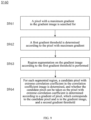
- FIG. 9 shows a schematic flow diagram of step S160 according to another embodiment of the present invention.
- step S160 can include steps S961, S962, S963, and S964.
- step S96 a pixel with a maximum gradient in the gradient image is searched for.
- the operation of this step is similar to the previous step S661, except that the pixel with maximum searched gradient is no longer taken as the pixel with extreme gradient.
- step S962 a first gradient threshold is determined according to the pixel with maximum gradient.
- step S963 region segmentation is performed on the gradient image according to the first gradient threshold.
- region segmentation the possible positions of the pixel with extreme gradient can be determined. Furthermore, it can help to determine the pixel with extreme correlation coefficient in the correlation coefficient image.
- the gradient image can be segmented directly by the threshold segmentation method according to the first gradient threshold.
- step S963 may include the following sub-steps: first, a progressive scan of the gradient image is performed according to the first gradient threshold, to search for seed pixels larger than the first gradient threshold. Then, region segmentation on the gradient image is performed according to the seed pixels, to obtain all of the segmented regions.
- region segmentation on the gradient image is performed according to a region growing algorithm by taking the seed pixels as the starting point.
- the region growing algorithm is a mature image segmentation algorithm, which can more accurately determine the possible regions of the pixel with extreme gradient in the gradient image, so as to ensure the accuracy of image registration.
- step S964 for each segmented region, a candidate pixel with extreme correlation coefficient in the correlation coefficient image is determined, and whether the candidate pixel can be taken as the pixel with extreme correlation coefficient is determined according to the gradient of pixel, which corresponds to the candidate pixel and is in the gradient image, and a second gradient threshold.
- the following operations for the segmented region can be performed until the pixel with extreme correlation coefficient is obtained.
- the corresponding pixel in the gradient image is determined according to the position of the candidate pixel with extreme the correlation coefficient image.
- the images shown in FIG. 7 and FIG. 8 are taken as an example.
- the position of the candidate pixel with an extreme correlation coefficient of 8.4340 in the correlation coefficient image is Row 6 and Column 4.
- the corresponding pixel on this position in the gradient image is determined to be 2.1060.
- Whether the candidate pixel can be taken as the pixel with extreme correlation coefficient is determined according to the gradient of pixel, which corresponds to the candidate pixel and is in the gradient image, and a second gradient threshold determined by the pixel with maximum gradient in segmented region.
- the second gradient threshold can be determined according to the pixel with maximum gradient in the segmented region multiplied by a specific coefficient.
- the value range of this particular coefficient may be [0.15, 0.25]. If the candidate pixel can be taken as the pixel with extreme correlation coefficient, the reference image and the floating image can be registered according to the candidate pixel, that is, step S180 is executed. If the candidate pixel cannot be taken as the pixel with extreme correlation coefficient, the new candidate pixel is searched for again and whether the new candidate pixel can be taken as the pixel with extreme correlation coefficient is determined again until the pixel with extreme correlation coefficient is obtained.
- the candidate pixel is taken as the pixel with extreme correlation coefficient, and it can be directly used for registration of the reference image and the floating image. Otherwise, go to the next segmented region to rerun operations 1) to 4) until the pixel with extreme correlation coefficient in the correlation coefficient image is determined.
- step S963 a seed pixel can be found first, a segmented region is obtained through the region growing algorithm, and then step S964 is performed for the segmented region. If the pixel with extreme correlation coefficient in the correlation coefficient image is determined in step S964, the method can proceed to step S 180; otherwise, go back to step S963, another seed pixel is found by scanning the gradient image, and another segmented region is obtained by the region growing algorithm. Then, the operations are similar to those described above. Repeat the above operation, until the pixel with extreme correlation coefficient in the correlation coefficient image is determined.
- step S963 all the segmented regions are obtained by region segmentation.
- step S964 if the pixel with extreme correlation coefficient is not obtained in a segmented region, proceed directly to the next region until the pixel with extreme correlation coefficient is obtained.
- step S961 step S962, step S963 and step S964 for determining the pixel with extreme correlation coefficient in the correlation coefficient image according to the pixel with extreme gradient in the gradient image
- the problem that the point with maximum gradient does not appear in the position of real displacement when the quality of image is poor or the size of image is too small can be avoided.
- the gradient of correlation coefficient near the wrong position is the largest, the gradient changes gently, while the gradient near the real position changes sharply. Therefore, in the above method, the region of which the gradient is large but change gently is eliminated according to the gradient change.
- the position of the true displacement in the correlation coefficient image can be predicted more reasonably, which ensures the accuracy of the registration operation.
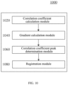
- FIG. 10 shows the image registration apparatus 1000 according to an embodiment of the present invention.
- the image registration apparatus 1000 includes a correlation coefficient calculation module 1020, a gradient calculation module 1040, a correlation coefficient peak determination module 1060 and a registration module 1080.
- the correlation coefficient calculation module 1020 is configured to calculate a correlation coefficient image between a reference image and a floating image.
- the gradient calculation module 1040 is configured to calculate a gradient image of the correlation coefficient image.
- the correlation coefficient peak determination module 1060 is configured to determine a pixel with extreme correlation coefficient in the correlation coefficient image according to a pixel with extreme gradient in the gradient image.
- the registration module 1080 is configured to register the reference image and the floating image according to the pixel with extreme correlation coefficient.
- the correlation coefficient peak determination module 1060 includes:
- the first finding sub-module includes: a search point determination unit, configured to determine an adjacent pixel of the corresponding pixel in the correlation coefficient image as a search point; and a finding unit, configured to traverse adjacent pixels of the search point, if the adjacent pixels are all smaller than the search point, the search point is taken as the pixel with extreme correlation coefficient; otherwise, a maximum adjacent pixel is taken as a new search point for re-finding.
- a search point determination unit configured to determine an adjacent pixel of the corresponding pixel in the correlation coefficient image as a search point
- a finding unit configured to traverse adjacent pixels of the search point, if the adjacent pixels are all smaller than the search point, the search point is taken as the pixel with extreme correlation coefficient; otherwise, a maximum adjacent pixel is taken as a new search point for re-finding.
- the correlation coefficient peak determination module 1060 includes:
- the segmentation sub-module includes:
- the segmentation unit includes a segmentation execution sub-unit, configured to, perform region segmentation on the gradient image according to a region growing algorithm by taking the seed pixels as the starting point.
- the above image registration apparatus may include a memory and a processor.
- the memory is configured to store program
- the processor is configured to run the program.
- the program is used to perform the above image registration method when being run by the processor.
- the program is used to perform the following steps when being run by the processor:
- an image stitching method is further provided.
- the image stitching method includes the steps of registering the reference image and the floating image according to the above image registration method and the steps of stitching the reference image and the floating image according to the registered result.
- the accurate position relation between the reference image and the floating image is obtained quickly by image registration operation, so the image stitching operation can be faster and more accurate.
- FIG. 11 shows an image stitching method 1100 according to an embodiment of the present invention.
- the image stitching method 1100 includes a registering step and a stitching step.
- the registering step the reference image and the floating image are registered; and in the stitching step, the floating image is inserted into the canvas by a defoliation method.
- the defoliation method is only an example, not a limitation of the present invention, and other fusion methods can be adopted.
- the image stitching method 1100 can also include other steps.
- the image stitching method 1100 is described in detail in combination with FIG. 11 below.
- the first image is obtained and is placed at the center of the canvas.
- the first image is taken as the reference image.
- Another image adjacent to the first image is obtained from the buffer and taken as a floating image.
- Adjacent images usually mean the images are adjacent in the acquisition order.
- the image registration method described above is used to register the reference image and the floating image. Whether the extreme maximum correlation coefficient determined in the image registration method is less than the correlation coefficient threshold C1 is judged. If the correlation coefficient is less than the correlation coefficient threshold C7, it means that the acquisition apparatus such as the probe of the microscope moves too fast in the process of image acquisition.
- the image stitching method 1100 can also include determining the overlapping area between the reference image and the floating image.
- the overlapping area is greater than the first area threshold A 1 , it means that the acquisition apparatus moves too slow in the process of image acquisition, then the current floating image does not contain more meaningful image information, and the floating image can be discarded. If the overlapping area is less than the second area threshold A 2 , it also means that the acquisition apparatus moves too fast in the process of image acquisition. If the correlation coefficient is greater than or equal to the correlation coefficient threshold C1 and the overlapping area is greater than or equal to the second area threshold A2 and less than or equal to the first area threshold A1, the stitching operation is performed, for example, the floating image is inserted into the appropriate position in the canvas by the defoliation method. Optionally, after the stitching operation, the image stitching method 1100 can also include a step of updating the trajectory map of the acquisition apparatus.
- whether to start a new stitching sequence can be artificially decided. If it is decided to start a new stitching sequence, the current floating image is taken as a new reference image, and can be placed at the center of the canvas. Another image adjacent to the new reference image is taken from the buffer as a new floating image to perform registration and stitching operations again. If it is decided not to start a new stitching sequence, the existing stitching image (if it exists) can be saved and the operation is ended.
- the image stitching method 1100 may further include a step of prompting the user in various ways, so that the user knows the current situation in time and makes an appropriate operation selection. For example, the current floating image is marked with a border of a specific color.
- the stitching operation does not make much sense because the overlapping area of adjacent images is very large.
- the stitching operation does not make much sense because the overlapping area of adjacent images is very large.
- the current floating image can be discarded, and another image can be obtained from the buffer as a new floating image.
- the new floating image is registered and stitched with the reference image. This can also avoid unnecessary calculations and improve system efficiency.
- an image stitching device may perform the above image stitching method, and may include the image registration apparatus and the image stitching apparatus described above. Among them, the image registration apparatus is used for registering a reference image and a floating image according to the image registration method. The image stitching apparatus is configured to stitch the reference image and the floating image according to the registration result of the image registration apparatus.
- the above image stitching device may include a memory and a processor.
- the memory is configured to store program
- the processor is configured to run the program.
- the program is used to perform the following steps when being run by the processor:
- a storage medium is further provided according to the embodiments of the present invention.
- a program instruction is stored in the storage medium.
- the computer or processor is made to perform the corresponding steps of the image registration method or image stitching method according to the embodiments of the present invention, and is used to realize the corresponding modules or apparatuses in the image registration apparatuses or image stitching devices according to the embodiments of the present invention.
- the storage medium may include, for example, a memory card of a smart phone, a storage component of a tablet computer, a hard disk of a personal computer, a read-only memory (ROM), an erasable programmable read-only memory (EPROM), a portable compact disk read-only memory (CD-ROM), a USB memory, or any combination of the above storage mediums.
- the computer-readable storage medium can be any combination of one or more computer-readable storage medium.
- the disclosed device and methods can be realized in other ways.
- the apparatus embodiments described above are only schematic, for example, the division of the units is only a logical function division, and there can be another division method in actual implementation, for example, multiple units or components can be combined or integrated into another apparatus, or some features can be ignored or not implemented.
- Each component embodiment of the present invention may be implemented in hardware, in software modules running on one or more processors, or in combination thereof. It should be understood by those skilled in the art that some or all functions of some modules in the image registration apparatus and the image stitching device according to the embodiment of the present invention can be realized in practice by using a microprocessor or a digital signal processor (DSP).
- DSP digital signal processor
- the present invention may also be implemented as an apparatus program (for example, a computer program and a computer program product) for performing part or all of the methods described herein.
- Such a program to implement the present invention may be stored on a computer-readable medium, or may have one or more signals in the form. Such signals can be downloaded from Internet sites, or provided on carrier signals, or in any other form.
- any reference symbol between the brackets should not be constructed as a limitation on the claim.
- the word “include” does not exclude the presence of components or steps that are not listed in the claim.
- the word “a”, “an” or “one” that precedes the symbol does not exclude the existence of multiple such components.
- the present invention can be achieved by means of hardware including several different components and by means of a computer with appropriate programming. In the claims of the units of several apparatus listed, several of these apparatus can be embodied through the same hardware item.
- the use of words first, second, and third does not represent any order. These words can be interpreted as names.
Landscapes
- Engineering & Computer Science (AREA)
- Physics & Mathematics (AREA)
- General Physics & Mathematics (AREA)
- Theoretical Computer Science (AREA)
- Computer Vision & Pattern Recognition (AREA)
- Quality & Reliability (AREA)
- Image Analysis (AREA)
- Image Processing (AREA)
- Apparatus For Radiation Diagnosis (AREA)
- Photographic Developing Apparatuses (AREA)
- Dot-Matrix Printers And Others (AREA)
- Vehicle Body Suspensions (AREA)
- Magnetic Resonance Imaging Apparatus (AREA)
Applications Claiming Priority (3)
| Application Number | Priority Date | Filing Date | Title |
|---|---|---|---|
| CN201710958427.6A CN107705246B (zh) | 2017-10-16 | 2017-10-16 | 图像配准方法和图像拼接方法及装置 |
| EP18867368.5A EP3699862B1 (de) | 2017-10-16 | 2018-10-15 | Verfahren zur bildregistrierung sowie vorrichtung |
| PCT/CN2018/110251 WO2019076266A1 (zh) | 2017-10-16 | 2018-10-15 | 图像配准方法和图像拼接方法及装置 |
Related Parent Applications (2)
| Application Number | Title | Priority Date | Filing Date |
|---|---|---|---|
| EP18867368.5A Division-Into EP3699862B1 (de) | 2017-10-16 | 2018-10-15 | Verfahren zur bildregistrierung sowie vorrichtung |
| EP18867368.5A Division EP3699862B1 (de) | 2017-10-16 | 2018-10-15 | Verfahren zur bildregistrierung sowie vorrichtung |
Publications (3)
| Publication Number | Publication Date |
|---|---|
| EP4235571A2 true EP4235571A2 (de) | 2023-08-30 |
| EP4235571A3 EP4235571A3 (de) | 2023-09-06 |
| EP4235571B1 EP4235571B1 (de) | 2026-02-25 |
Family
ID=61185082
Family Applications (2)
| Application Number | Title | Priority Date | Filing Date |
|---|---|---|---|
| EP18867368.5A Active EP3699862B1 (de) | 2017-10-16 | 2018-10-15 | Verfahren zur bildregistrierung sowie vorrichtung |
| EP23169492.8A Active EP4235571B1 (de) | 2017-10-16 | 2018-10-15 | Verfahren zur bildregistrierung sowie vorrichtung |
Family Applications Before (1)
| Application Number | Title | Priority Date | Filing Date |
|---|---|---|---|
| EP18867368.5A Active EP3699862B1 (de) | 2017-10-16 | 2018-10-15 | Verfahren zur bildregistrierung sowie vorrichtung |
Country Status (13)
| Country | Link |
|---|---|
| US (1) | US11200687B2 (de) |
| EP (2) | EP3699862B1 (de) |
| JP (1) | JP6993651B2 (de) |
| KR (1) | KR102376800B1 (de) |
| CN (1) | CN107705246B (de) |
| AU (1) | AU2018352936B2 (de) |
| BR (1) | BR112020007581A2 (de) |
| CA (1) | CA3079037C (de) |
| ES (1) | ES2948236T3 (de) |
| MX (1) | MX2020004020A (de) |
| PL (1) | PL3699862T3 (de) |
| RU (1) | RU2747832C1 (de) |
| WO (1) | WO2019076266A1 (de) |
Families Citing this family (6)
| Publication number | Priority date | Publication date | Assignee | Title |
|---|---|---|---|---|
| CN107705246B (zh) * | 2017-10-16 | 2019-08-16 | 苏州微景医学科技有限公司 | 图像配准方法和图像拼接方法及装置 |
| CN112102295B (zh) * | 2020-09-17 | 2024-07-26 | 深圳市安健科技股份有限公司 | Dr图像配准方法、装置、终端和计算机可读存储介质 |
| US11551370B2 (en) | 2020-12-18 | 2023-01-10 | Nationwide Management Services, Inc. | Remote inspection and appraisal of buildings |
| CN113592922B (zh) * | 2021-06-09 | 2025-03-11 | 维沃移动通信(杭州)有限公司 | 图像的配准处理方法及装置 |
| CN113781533A (zh) * | 2021-09-10 | 2021-12-10 | 北京方正印捷数码技术有限公司 | 图像配准方法、装置、印刷机和存储介质 |
| CN115631219B (zh) * | 2022-09-28 | 2026-03-24 | 北京航天自动控制研究所 | 一种图像匹配的方式处理数据图像的判读方法及系统 |
Family Cites Families (13)
| Publication number | Priority date | Publication date | Assignee | Title |
|---|---|---|---|---|
| US5251271A (en) * | 1991-10-21 | 1993-10-05 | R. R. Donnelley & Sons Co. | Method for automatic registration of digitized multi-plane images |
| JP2005058428A (ja) * | 2003-08-11 | 2005-03-10 | Hitachi Ltd | 病巣位置特定システム及び放射線検査装置 |
| US7620269B1 (en) * | 2004-07-01 | 2009-11-17 | Sandia Corporation | Edge-based correlation image registration for multispectral imaging |
| FR2879791B1 (fr) * | 2004-12-16 | 2007-03-16 | Cnes Epic | Procede de traitement d'images mettant en oeuvre le georeferencement automatique d'images issues d'un couple d'images pris dans le meme plan focal |
| CN100571632C (zh) * | 2007-08-24 | 2009-12-23 | 珠海友通科技有限公司 | X线透视人体影像自动融合拼接方法 |
| US8086043B2 (en) * | 2007-12-21 | 2011-12-27 | Ati Technologies Ulc | System and method of image correlation based on image structure |
| US8345943B2 (en) * | 2008-09-12 | 2013-01-01 | Fujifilm Corporation | Method and apparatus for registration and comparison of medical images |
| CN102274042B (zh) * | 2010-06-08 | 2013-09-04 | 深圳迈瑞生物医疗电子股份有限公司 | 图像配准方法、宽景成像方法、超声成像方法及其系统 |
| CN101984463A (zh) * | 2010-11-02 | 2011-03-09 | 中兴通讯股份有限公司 | 全景图合成方法及装置 |
| KR20140119372A (ko) * | 2013-03-29 | 2014-10-10 | 삼성테크윈 주식회사 | 움직임량 예측 장치 및 방법 |
| CN103714547B (zh) * | 2013-12-30 | 2017-03-22 | 北京理工大学 | 一种结合边缘区域和互相关的图像配准方法 |
| RU2580473C1 (ru) * | 2014-12-29 | 2016-04-10 | Федеральное государственное бюджетное образовательное учреждение высшего профессионального образования "Донской государственный технический университет" (ФГБОУ ВПО "ДГТУ") | Устройство бесшовного объединения изображений в единую композицию с автоматической регулировкой контрастности и градиентом |
| CN107705246B (zh) * | 2017-10-16 | 2019-08-16 | 苏州微景医学科技有限公司 | 图像配准方法和图像拼接方法及装置 |
-
2017
- 2017-10-16 CN CN201710958427.6A patent/CN107705246B/zh active Active
-
2018
- 2018-10-15 AU AU2018352936A patent/AU2018352936B2/en not_active Ceased
- 2018-10-15 PL PL18867368.5T patent/PL3699862T3/pl unknown
- 2018-10-15 KR KR1020207012897A patent/KR102376800B1/ko not_active Expired - Fee Related
- 2018-10-15 CA CA3079037A patent/CA3079037C/en active Active
- 2018-10-15 BR BR112020007581-7A patent/BR112020007581A2/pt not_active IP Right Cessation
- 2018-10-15 WO PCT/CN2018/110251 patent/WO2019076266A1/zh not_active Ceased
- 2018-10-15 ES ES18867368T patent/ES2948236T3/es active Active
- 2018-10-15 EP EP18867368.5A patent/EP3699862B1/de active Active
- 2018-10-15 JP JP2020541845A patent/JP6993651B2/ja active Active
- 2018-10-15 EP EP23169492.8A patent/EP4235571B1/de active Active
- 2018-10-15 RU RU2020115412A patent/RU2747832C1/ru active
- 2018-10-15 MX MX2020004020A patent/MX2020004020A/es unknown
-
2020
- 2020-04-16 US US16/850,032 patent/US11200687B2/en active Active
Also Published As
| Publication number | Publication date |
|---|---|
| EP3699862B1 (de) | 2023-06-07 |
| CA3079037C (en) | 2022-10-25 |
| JP6993651B2 (ja) | 2022-01-13 |
| JP2020537276A (ja) | 2020-12-17 |
| EP3699862A4 (de) | 2020-11-18 |
| EP3699862A1 (de) | 2020-08-26 |
| RU2747832C1 (ru) | 2021-05-14 |
| KR20200057086A (ko) | 2020-05-25 |
| CN107705246A (zh) | 2018-02-16 |
| PL3699862T3 (pl) | 2023-11-20 |
| WO2019076266A1 (zh) | 2019-04-25 |
| MX2020004020A (es) | 2020-08-13 |
| KR102376800B1 (ko) | 2022-03-21 |
| CA3079037A1 (en) | 2019-04-25 |
| AU2018352936A1 (en) | 2020-05-14 |
| EP4235571A3 (de) | 2023-09-06 |
| ES2948236T3 (es) | 2023-09-06 |
| BR112020007581A2 (pt) | 2020-09-24 |
| US11200687B2 (en) | 2021-12-14 |
| US20200242786A1 (en) | 2020-07-30 |
| AU2018352936B2 (en) | 2021-04-01 |
| CN107705246B (zh) | 2019-08-16 |
| EP4235571B1 (de) | 2026-02-25 |
Similar Documents
| Publication | Publication Date | Title |
|---|---|---|
| EP4235571B1 (de) | Verfahren zur bildregistrierung sowie vorrichtung | |
| US20140177941A1 (en) | Optimal Patch Ranking for Coordinate Transform Estimation of Microscope Images from Sparse Patch Shift Estimates | |
| CN111583120A (zh) | 图像拼接方法、装置、设备和存储介质 | |
| CN106296587B (zh) | 轮胎模具图像的拼接方法 | |
| US7440628B2 (en) | Method and system for motion correction in a sequence of images | |
| JP2020095668A (ja) | 道路画像再構成及び車両測位のための方法及びシステム | |
| CN115205113B (zh) | 一种图像拼接方法、装置、设备及存储介质 | |
| CN112862676A (zh) | 一种图像拼接方法、设备、存储介质 | |
| CN112102295A (zh) | Dr图像配准方法、装置、终端和计算机可读存储介质 | |
| CN118552403B (zh) | 一种基于电动显微镜的图像拼接方法及装置 | |
| US10853909B2 (en) | Image processing apparatus | |
| EP4621701A1 (de) | Verfahren zum zusammenfügen von bildern und vorrichtung dafür | |
| CN110100263B (zh) | 图像重建方法及装置 | |
| CN118097000A (zh) | 一种超声超分辨成像的重叠微泡定位方法及相关设备 | |
| CN116212301A (zh) | 一种立定跳远成绩的测定方法、系统、装置和介质 | |
| CN115705656B (zh) | 一种相关滤波目标跟踪方法、系统及存储介质 | |
| JP3657725B2 (ja) | 線図形画像処理方法 | |
| JP3539632B2 (ja) | 画像変化抽出方法、およびその画像処理プログラム | |
| JP2001331303A (ja) | 描画処理装置および描画処理方法並びに描画処理プログラムを記憶した記憶媒体 | |
| CN117349554A (zh) | Pdf文件的电子签章方法、装置、前端、后端及介质 | |
| CN119672164A (zh) | 地震道头属性图绘制显示方法、装置、电子设备及介质 | |
| CN121861084A (zh) | 图像偏移确定方法、装置、电子设备和存储介质 | |
| CN116934839A (zh) | 嗜铬细胞瘤/副神经节瘤图形位置的自动调整方法及装置 | |
| CN115578250A (zh) | 用于处理全景拼接图像的方法和设备 | |
| Boin | Improving feature tracking using motion sensors |
Legal Events
| Date | Code | Title | Description |
|---|---|---|---|
| PUAI | Public reference made under article 153(3) epc to a published international application that has entered the european phase |
Free format text: ORIGINAL CODE: 0009012 |
|
| STAA | Information on the status of an ep patent application or granted ep patent |
Free format text: STATUS: REQUEST FOR EXAMINATION WAS MADE |
|
| PUAL | Search report despatched |
Free format text: ORIGINAL CODE: 0009013 |
|
| 17P | Request for examination filed |
Effective date: 20230424 |
|
| AC | Divisional application: reference to earlier application |
Ref document number: 3699862 Country of ref document: EP Kind code of ref document: P |
|
| AK | Designated contracting states |
Kind code of ref document: A2 Designated state(s): AL AT BE BG CH CY CZ DE DK EE ES FI FR GB GR HR HU IE IS IT LI LT LU LV MC MK MT NL NO PL PT RO RS SE SI SK SM TR |
|
| AK | Designated contracting states |
Kind code of ref document: A3 Designated state(s): AL AT BE BG CH CY CZ DE DK EE ES FI FR GB GR HR HU IE IS IT LI LT LU LV MC MK MT NL NO PL PT RO RS SE SI SK SM TR |
|
| RIC1 | Information provided on ipc code assigned before grant |
Ipc: G06T 7/32 20170101AFI20230731BHEP |
|
| RBV | Designated contracting states (corrected) |
Designated state(s): AL AT BE BG CH CY CZ DE DK EE ES FI FR GB GR HR HU IE IS IT LI LT LU LV MC MK MT NL NO PL PT RO RS SE SI SK SM TR |
|
| STAA | Information on the status of an ep patent application or granted ep patent |
Free format text: STATUS: EXAMINATION IS IN PROGRESS |
|
| 17Q | First examination report despatched |
Effective date: 20250530 |
|
| GRAP | Despatch of communication of intention to grant a patent |
Free format text: ORIGINAL CODE: EPIDOSNIGR1 |
|
| STAA | Information on the status of an ep patent application or granted ep patent |
Free format text: STATUS: GRANT OF PATENT IS INTENDED |
|
| INTG | Intention to grant announced |
Effective date: 20251020 |
|
| GRAS | Grant fee paid |
Free format text: ORIGINAL CODE: EPIDOSNIGR3 |
|
| GRAA | (expected) grant |
Free format text: ORIGINAL CODE: 0009210 |
|
| STAA | Information on the status of an ep patent application or granted ep patent |
Free format text: STATUS: THE PATENT HAS BEEN GRANTED |
|
| AC | Divisional application: reference to earlier application |
Ref document number: 3699862 Country of ref document: EP Kind code of ref document: P |
|
| AK | Designated contracting states |
Kind code of ref document: B1 Designated state(s): AL AT BE BG CH CY CZ DE DK EE ES FI FR GB GR HR HU IE IS IT LI LT LU LV MC MK MT NL NO PL PT RO RS SE SI SK SM TR |
|
| REG | Reference to a national code |
Ref country code: CH Ref legal event code: F10 Free format text: ST27 STATUS EVENT CODE: U-0-0-F10-F00 (AS PROVIDED BY THE NATIONAL OFFICE) Effective date: 20260225 Ref country code: GB Ref legal event code: FG4D |
|
| REG | Reference to a national code |
Ref country code: DE Ref legal event code: R096 Ref document number: 602018089502 Country of ref document: DE |
|
| REG | Reference to a national code |
Ref country code: IE Ref legal event code: FG4D |