EP4235364A2 - Système et procédé de prévention de la détérioration de la vue causée par un travail de proximité avec des dispositifs à écrans électroniques - Google Patents
Système et procédé de prévention de la détérioration de la vue causée par un travail de proximité avec des dispositifs à écrans électroniques Download PDFInfo
- Publication number
- EP4235364A2 EP4235364A2 EP23160165.9A EP23160165A EP4235364A2 EP 4235364 A2 EP4235364 A2 EP 4235364A2 EP 23160165 A EP23160165 A EP 23160165A EP 4235364 A2 EP4235364 A2 EP 4235364A2
- Authority
- EP
- European Patent Office
- Prior art keywords
- user
- distance
- head
- calibration
- processing circuitry
- Prior art date
- Legal status (The legal status is an assumption and is not a legal conclusion. Google has not performed a legal analysis and makes no representation as to the accuracy of the status listed.)
- Pending
Links
- 238000000034 method Methods 0.000 title claims abstract description 66
- 230000006866 deterioration Effects 0.000 title claims abstract description 36
- 238000012545 processing Methods 0.000 claims abstract description 92
- 238000004590 computer program Methods 0.000 claims 1
- 230000004515 progressive myopia Effects 0.000 abstract description 10
- 210000003128 head Anatomy 0.000 description 79
- 230000008569 process Effects 0.000 description 38
- 230000004048 modification Effects 0.000 description 9
- 238000012986 modification Methods 0.000 description 9
- 230000035945 sensitivity Effects 0.000 description 6
- 230000000694 effects Effects 0.000 description 4
- 238000002604 ultrasonography Methods 0.000 description 4
- 230000006870 function Effects 0.000 description 3
- 230000007246 mechanism Effects 0.000 description 3
- 230000004379 myopia Effects 0.000 description 3
- 208000001491 myopia Diseases 0.000 description 3
- 230000008901 benefit Effects 0.000 description 2
- 238000001514 detection method Methods 0.000 description 2
- 210000001508 eye Anatomy 0.000 description 2
- 230000005693 optoelectronics Effects 0.000 description 2
- 230000002035 prolonged effect Effects 0.000 description 2
- 230000004044 response Effects 0.000 description 2
- 201000004569 Blindness Diseases 0.000 description 1
- 208000003556 Dry Eye Syndromes Diseases 0.000 description 1
- 206010013774 Dry eye Diseases 0.000 description 1
- 206010019233 Headaches Diseases 0.000 description 1
- 206010050031 Muscle strain Diseases 0.000 description 1
- 206010047513 Vision blurred Diseases 0.000 description 1
- 230000004308 accommodation Effects 0.000 description 1
- 208000003464 asthenopia Diseases 0.000 description 1
- 210000005252 bulbus oculi Anatomy 0.000 description 1
- 230000001413 cellular effect Effects 0.000 description 1
- 230000008859 change Effects 0.000 description 1
- 210000003161 choroid Anatomy 0.000 description 1
- 230000005786 degenerative changes Effects 0.000 description 1
- 238000010586 diagram Methods 0.000 description 1
- 238000006073 displacement reaction Methods 0.000 description 1
- 239000003814 drug Substances 0.000 description 1
- 229940079593 drug Drugs 0.000 description 1
- 231100000869 headache Toxicity 0.000 description 1
- 238000005286 illumination Methods 0.000 description 1
- 230000001939 inductive effect Effects 0.000 description 1
- 230000007774 longterm Effects 0.000 description 1
- 230000004423 myopia development Effects 0.000 description 1
- 210000005157 neural retina Anatomy 0.000 description 1
- 230000003287 optical effect Effects 0.000 description 1
- 230000000144 pharmacologic effect Effects 0.000 description 1
- 230000002265 prevention Effects 0.000 description 1
- 230000000750 progressive effect Effects 0.000 description 1
- 230000005180 public health Effects 0.000 description 1
- 210000003583 retinal pigment epithelium Anatomy 0.000 description 1
- 210000003786 sclera Anatomy 0.000 description 1
- 238000002560 therapeutic procedure Methods 0.000 description 1
- 230000000007 visual effect Effects 0.000 description 1
Images


Classifications
-
- G—PHYSICS
- G06—COMPUTING; CALCULATING OR COUNTING
- G06F—ELECTRIC DIGITAL DATA PROCESSING
- G06F3/00—Input arrangements for transferring data to be processed into a form capable of being handled by the computer; Output arrangements for transferring data from processing unit to output unit, e.g. interface arrangements
- G06F3/01—Input arrangements or combined input and output arrangements for interaction between user and computer
- G06F3/017—Gesture based interaction, e.g. based on a set of recognized hand gestures
-
- G—PHYSICS
- G06—COMPUTING; CALCULATING OR COUNTING
- G06F—ELECTRIC DIGITAL DATA PROCESSING
- G06F3/00—Input arrangements for transferring data to be processed into a form capable of being handled by the computer; Output arrangements for transferring data from processing unit to output unit, e.g. interface arrangements
- G06F3/01—Input arrangements or combined input and output arrangements for interaction between user and computer
- G06F3/011—Arrangements for interaction with the human body, e.g. for user immersion in virtual reality
- G06F3/012—Head tracking input arrangements
-
- G—PHYSICS
- G06—COMPUTING; CALCULATING OR COUNTING
- G06F—ELECTRIC DIGITAL DATA PROCESSING
- G06F3/00—Input arrangements for transferring data to be processed into a form capable of being handled by the computer; Output arrangements for transferring data from processing unit to output unit, e.g. interface arrangements
- G06F3/01—Input arrangements or combined input and output arrangements for interaction between user and computer
- G06F3/011—Arrangements for interaction with the human body, e.g. for user immersion in virtual reality
- G06F3/013—Eye tracking input arrangements
-
- G—PHYSICS
- G06—COMPUTING; CALCULATING OR COUNTING
- G06F—ELECTRIC DIGITAL DATA PROCESSING
- G06F3/00—Input arrangements for transferring data to be processed into a form capable of being handled by the computer; Output arrangements for transferring data from processing unit to output unit, e.g. interface arrangements
- G06F3/14—Digital output to display device ; Cooperation and interconnection of the display device with other functional units
- G06F3/147—Digital output to display device ; Cooperation and interconnection of the display device with other functional units using display panels
-
- G—PHYSICS
- G06—COMPUTING; CALCULATING OR COUNTING
- G06T—IMAGE DATA PROCESSING OR GENERATION, IN GENERAL
- G06T7/00—Image analysis
- G06T7/70—Determining position or orientation of objects or cameras
-
- G—PHYSICS
- G09—EDUCATION; CRYPTOGRAPHY; DISPLAY; ADVERTISING; SEALS
- G09G—ARRANGEMENTS OR CIRCUITS FOR CONTROL OF INDICATING DEVICES USING STATIC MEANS TO PRESENT VARIABLE INFORMATION
- G09G5/00—Control arrangements or circuits for visual indicators common to cathode-ray tube indicators and other visual indicators
-
- G—PHYSICS
- G06—COMPUTING; CALCULATING OR COUNTING
- G06V—IMAGE OR VIDEO RECOGNITION OR UNDERSTANDING
- G06V40/00—Recognition of biometric, human-related or animal-related patterns in image or video data
- G06V40/10—Human or animal bodies, e.g. vehicle occupants or pedestrians; Body parts, e.g. hands
- G06V40/16—Human faces, e.g. facial parts, sketches or expressions
-
- G—PHYSICS
- G09—EDUCATION; CRYPTOGRAPHY; DISPLAY; ADVERTISING; SEALS
- G09G—ARRANGEMENTS OR CIRCUITS FOR CONTROL OF INDICATING DEVICES USING STATIC MEANS TO PRESENT VARIABLE INFORMATION
- G09G2354/00—Aspects of interface with display user
Definitions
- This is related to the fields of visual optics, physiological optics, electronics and computers.
- this is related to systems and methods of preventing sight problems, such as myopia, that are due to the prolonged use of electronic screens at short distances.
- the prolonged use of portable devices can cause ocular conditions such as eye fatigue, blurred vision, headaches, muscle strain and dry eye. It may also be one of the causes of myopia progression in the long term.
- Myopia (or short-sightedness) is associated with the progressive and excessive elongation of the ocular globe, which may be accompanied by degenerative changes in the sclera, choroid, retinal pigment epithelium and neural retina. It is a significant public health problem worldwide, and a leading cause of blindness with a rapid increase in prevalence in recent decades.
- a system can include, in addition to an electronic screen, a distance sensor directed towards a user.
- a system can also include processing circuitry coupled to a distance sensor and control circuitry coupled to an electronic screen. If a processing circuitry determines that a distance between a user's head and a device is shorter than a calibration distance, it can send a control signal to control circuitry to notify a user. If a processing circuitry determines that said distance is equal or longer than a calibration distance, a control circuitry can stop notifications or not initiate them.
- a device can modify an operation of an electronic screen, based on a relation between actual distance between a user's head and a device, determined by processing circuitry, relative to a calibration distance. For example, a user can be using a device at a close distance that may put the user at risk of sight deterioration. Processing circuitry coupled to a distance sensor of a device can then determine said relative distance using the calibration distance, and notify a user by, for example: blurring, darkening or changing a color of an electronic screen, which can make a user instinctively move a device away. As another example, a device can notify a user by displaying information on a screen, emitting a sound from a speaker, vibrating a device or a combination of any of the above.
- An electronic device can determine a distance between a user and an electronic screen using a distance sensor directed towards a user and notify the user if the distance is shorter than a calibration distance, putting the user at risk of sight deterioration and progression of myopia.
- an electronic device can include a camera coupled to a processing circuitry for passive detection of a user's head.
- Image processing circuitry can analyze images from a camera (e.g., single pictures or video frames) and determine if they contain an image of at least a part of a user's head (hereinafter referred to as "user's head").
- images that contain an image of a user's head can be analyzed to determine a distance between a user's head and a device. If a processing circuitry determines that a distance between a user's head and a device is shorter than a calibration distance, it can send a control signal to control circuitry to notify a user, for example by showing an information on a screen, emitting a sound from a speaker, or vibrating a device. On the other hand, if a processing circuitry determines that a distance between a user's head and a device is equal or longer than a calibration distance, the control circuitry can stop notifications or not initiate them.
- Control circuitry can also modify operation of a device or one or more components of a device, for example by blurring, darkening or changing a color of an electronic screen, with the finality of making a user instinctively move a device away. Furthermore, strength of this modification can be modulated by a ratio between a distance between a user's head and a device relative to a calibration distance. For example, a screen can be made progressively more blurred, or darker as said ratio becomes smaller.
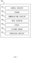
- FIG. 1 is a schematic overview of an illustrative electronic device for preventing sight deterioration caused by near work with devices with electronic screens in accordance with one embodiment of the invention.
- Electronic device 100 can include control circuitry 101, storage 102, communications circuitry 103, input interface 104, screen 105, distance sensor 106 and processing circuitry 107.
- one or more of device's components can be combined or omitted.
- a distance sensor 106 can include two cameras combined into a single mechanism for stereoscopic distance determination.
- electronic device 100 can include other components not included in FIG. 1 , such as: a vibration component; a speaker; a microphone; an accelerometer; a gyroscope; or a combination of any of the aforementioned components.
- Electronic device 100 can include any suitable type of device with an electronic screen and a capability to determine a distance between a user's head and a device.
- electronic device 100 can include any of the following devices equipped with a camera: a mobile phone, a tablet, a "smart" television set, a personal digital assistant (PDA), a laptop or desktop computer, a stand-alone camera or video-recorder, and any other suitable device.
- PDA personal digital assistant
- Control circuitry 101 can include any circuitry and processors designed to control the functions, operations and performance of an electronic device 100.
- Storage 102 can include one or more storage mediums, such as internal or external memory of any type, such as: HDD, SSD, RAM, ROM, flash memory such as an SD (i.e. Secure Digital) card of CF (i.e. Compact Flash) card, or any other type of memory suitable for device 100.
- Communications circuitry 103 can include any circuitry suitable to connect a device to a communications network and transmit communications using any suitable protocol such as, for example, Wi-Fi (e.g., a 802.11 protocol), Bluetooth ® , cellular protocol (e.g., GSM, GPRS, CDMA, EDGE, LTE), or any other communications protocol or any combination thereof.
- Input interface 104 can include any suitable mechanism for receiving inputs from a user.
- Screen 105 can include any suitable mechanism for displaying information to a user.
- screen 105 can include a screen control circuitry 101 for controlling the level of illumination.
- screen 105 can be electronically coupled with control circuitry 101 and other components within an electronic device 100, or any combination thereof.
- Distance sensor 106 can include any suitable device for determining a distance between a user's head and a device.
- distance sensor 106 can include one or more cameras coupled to processing circuitry 107 for processing output images of a camera (e.g., single pictures or video frames) and passive determination of a distance between a user's head and a device.
- distance sensor 106 can include a signal emitter and a sensor for active determination of a distance between a user's head and a device.
- distance sensor 106 can include an emitter of infrared light and an optoelectronic sensor of infrared light coupled to processing circuitry 107 for signal processing and distance determination.
- distance sensor 106 can include an ultrasound emitter and an ultrasound-sensitive microphone coupled to processing circuitry 107 for signal processing and distance determination. Furthermore, in some embodiments, distance sensor 106 can include a combination of both active and passive components for determination of distance between a user's head and a device.
- an electronic device can determine a distance between a user and an electronic screen using a distance sensor directed towards a user and notify the user if the distance is shorter than a calibration distance.
- the combination of a device capable of determining a distance between the device and a user, that furthermore can notify a user when said distance is closer than a calibration distance, can form a system for preventing sight deterioration.
- FIG. 2a is a schematic view of system 200 for preventing sight deterioration in accordance with one embodiment of the invention where a camera is used as a distance sensor.
- System 200 can include an electronic device 210a that can include a camera 215 and processing circuitry 214 to detect a user's head 290 using ambient light 292 reflected diffusely 291 from a user's head 290.
- Electronic device 210 can be very similar to electronic device 100 shown in FIG. 1 and share descriptions of components of the latter.
- electronic device 210 can include control circuitry 211, storage 212, screen 213, and processing circuitry 214 that can be substantially similar to respective components of electronic device 100; control circuitry 101, storage 102, screen 105 and processing circuitry 107.
- Electronic device 210 can also include other suitable components such as communications circuitry 103, and input interface 104 shown in FIG. 1 .
- Processing circuitry 214 can use any suitable technique or combination of techniques for processing output images (e.g., single pictures or video frames) of a camera 215, detecting if they contain an image of a user's head 290, and determining if a distance between a user's head 290 and a device is shorter than a calibration distance, putting a user at risk of sight deterioration and myopia progression. If an image of a user's head is detected, processing circuitry 214 can use any suitable technique or combination of techniques for determining a distance between a user's head 290 and a device. For example, processing circuitry 214 can determine a distance between a user's head 290 and a device relative to a similar distance obtained in a calibration procedure. More specifically, the processing circuitry can determine this relation based upon a number of pixels subtended by an image of the user's head, and a similar number of pixels obtained in the calibration procedure.
- output images e.g., single pictures or video frames
- processing circuitry 214 can
- control circuitry 211 can then perform a function based on said control signal. For example, control circuitry 211 can instruct screen 213 to show information to a user or to modify its operation (e.g., darken, blur or change a color of the screen).
- a distance between a user's head 290 and a device, determined by processing circuitry 214 is equal or longer than a calibration distance (i.e., their ratio is lower than 1), or if an image of a head is not detected by processing circuitry 214, it can send a control signal to control circuitry 211, which in turn can instruct the screen 213 to cease a modification of its operation.
- said modification of operation of screen 213 can be substituted by a modification of operation of another component of a device 200, such as: strength of a vibration component; volume of a sound emitted from a speaker; or any combination of any of the aforementioned modifications.
- the strength of this modification of operation of screen 213 can be modulated by control circuitry 211 in response to a control signal from processing circuitry 214.
- a screen can be made progressively more blurred, or darker as said ratio becomes smaller.
- processing circuitry 214 can perform processing and analysis of consecutive frames (e.g., images in a video stream) in order to determine a distance between a user's head and a device continuously, at a frame rate determined by a camera 215.
- control circuitry 211 can modify the frame rate to improve performance.
- the frame rate of processing and analysis performed by processing circuitry 214 can be modified by control circuitry 211 according to a user's input provided by an equivalent of input interface 104 in electronic device 210.
- processing circuitry 214 can, in order to accurately determine a distance between a user's head 290 and a device, take into account various parameters of camera 215, such as: physical dimensions of the camera's sensor; size of an image from the camera; focal length the camera's lens; other camera parameters; any combination of any of the above. Furthermore, to the same end, processing circuitry 214 can make use of additional capabilities of camera 215, such as auto-focus or exposure control or others, or any combination of any of the above. For example, any suitable processing circuitry 214 can determine insufficient exposure of an image of a user's head 290 and send a control signal to control circuitry 211 to increase exposure of a camera 215.
- system 200 can include electronic device 210b, which can include two cameras combined into a single distance sensor 216 equivalent to a distance sensor 106 in electronic device 100 as presented in a schematic illustration of system 200 in FIG. 2b .
- processing circuitry 214 can determine a distance between a user's head 290 and a device stereoscopically, based on two images from two cameras, and additional parameters such as: physical displacement between cameras; physical angle between optical axes of cameras; focal lengths of cameras' lenses; physical dimensions of cameras' sensors; or others; or any combination of any of the above.
- system 200 can include electronic device 210c, which can include a sensor and an emitter combined into a single distance sensor 217 equivalent to a distance sensor 106 in electronic device 100 as presented in a schematic illustration of system 200 in FIG. 2c .
- a sensor component of distance sensor 217 can include one of the following sensors: an inductive sensor, a capacitive sensor, a photoelectric sensor, an optoelectronic sensor, a magnetic sensor, a sonic sensor, or any combination of any of the above.
- a corresponding emitter component of distance sensor 217 can include any suitable device capable of emitting a signal detectable by said sensor component.
- said emitter component can include an ultrasound speaker coupled to control circuitry 211
- said sensor component can include a microphone sensitive to ultrasounds, coupled to a processing circuitry 214.
- processing circuitry 214 can determine a distance between a user's head 290 and a device based on a signal 293 emitted towards a user's head by an emitter component of distance sensor 217, reflected 294 from the head 290 and detected by a sensor component of distance sensor 217.
- Control circuitry 211 can send control signals to modify parameters of distance sensor 217, such as power of emitted signal or power of detected signal.
- control circuitry 211 can send a control signal to an emitter component of distance sensor 217 to increase output of emitted signal, after receiving a control signal sent by processing circuitry 214, in response to insufficient power of a signal detected by a sensor component of distance sensor 217.
- a user can configure a system to prevent sight deterioration.
- a user can be able to configure parameters to control: detecting a user's head; determining a distance between a user and a device (e.g., sensitivity); modifying an operation of a device (e.g., effect type, strength); or notifying a user.
- a device e.g., sensitivity
- modifying an operation of a device e.g., effect type, strength
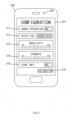
- FIG. 3 is an example view of an illustrative screen for configuring an electronic device to prevent sight deterioration in accordance with one embodiment of the invention.
- Device 300 can be an electronic device with a screen 307 and a camera 308 used as a distance sensor.
- Device 300 can be substantially similar to device 100 shown in FIG. 1 and device 210 shown in FIG. 2a -c and share descriptions of components with any or all of the latter.
- device 300 can include a distance sensor including one or more cameras 308 for capturing images of a user's head (corresponding to distance sensor 106 in FIG. 1 and distance sensor 215 in FIG. 2a , and 216 in FIG. 2b ).
- Device 300 can include a screen 307 (see, e.g., screen 105 in FIG. 1 and screen 213 in FIG. 2a- c) and any other suitable electronic device components or any combination thereof.
- Configuration screen 307 can be shown on screen 307 and include parameters to control: detecting a user's head 290; determining a distance between a user's head 290 and a device 300; modifying an operation of a device; notifying a user.
- a configuration screen 307 can include a setting 311 for enabling or disabling a prevention of sight deterioration generally. For example, a user can set setting 311 to "OFF", so that device 300 cannot perform functions of a system for preventing sight deterioration.
- setting 311 can be set to "ON" so that the device can determine a distance between the device and a user's head 290, and notify a user when the said distance is shorter than a calibration distance.
- a configuration screen 307 can include a setting 312, corresponding to a modification of operation of a device.
- a user can set setting 312 to "BLUR SCREEN", to specify the type of modification of operation of a device. More specifically, the value of setting 312 can instruct control circuitry in device 300 (see, e.g., control circuitry 101 shown in FIG. 1 and control circuitry 211 in FIG. 2a ) to blur information displayed on a screen of a device.
- a user can set setting 312 to "DARKEN SCREEN”, “WARNING SOUND”, “VIBRATION” or “FLASHING INFO”, to instruct control circuitry in device 300 to perform respectively: darkening information displayed on a screen of a device; emitting a sound from a speaker of a device; vibrating a vibrating component of a device; showing an information message to a user on a screen, or any combination of any of the above.
- configuration screen 307 can include a setting 313, corresponding to a sensitivity of determination of a distance between a user's head 290 and a device.
- a user can set setting 313 on a sliding scale between "LOW” and "HIGH”, to specify sensitivity. More specifically, the value of setting 313 can modify the sensitivity of processing circuitry in device 300 (see, e.g., processing circuitry 107 in FIG. 1 and processing circuitry 214 in FIG. 2a -c). If option 313 is set to "LOW" sensitivity, said processing circuitry of device 300 can notify a user only when said distance is much shorter than said calibration distance.
- configuration screen 307 can include a setting 314, corresponding to strength of a modification of operation of a device.
- a user can set setting 314 on a sliding scale between "LOW” and "HIGH”, to specify strength. More specifically, the value of setting 314 can modify the functioning of control circuitry in device 300 (see, e.g., control circuitry 101 shown in FIG. 1 and control circuitry 211 in FIG. 2a -c).
- option 314 is set to "LOW" strength, an operation of device 300 can only be modified a small amount in accordance with effect type 312 (e.g. a information displayed on a screen of a device can be blurred by a small amount).
- option 314 is set to a "HIGH” strength, an operation of device 300 can be modified a large amount in accordance with effect type 312 (e.g. a information displayed on a screen can be blurred beyond legibility).
- configuration screen 307 can include a setting 315 for enabling or disabling storage of information used by processing circuitry, control circuitry, distance sensor or other components of device 300.
- a user can set setting 315 to "OFF" so that device 300 will not store information.
- setting 315 is set to "ON" so that device 300 stores information.
- setting 315 can correspond to an equivalent of storage 102 in FIG. 1 to store information in memory of device 300, or an equivalent of communications circuitry 103 in FIG. 1 of device 300 to store information using a network. It is understood that, in embodiments where processing circuitry performs processing and analysis of signals and data, certain information must be temporarily stored in memory of a device and a user cannot be able to set configuration settings to disable such storage.
- a user can calibrate a system to prevent sight deterioration.
- a user can be able to calibrate a relation between a physical distance from a user's head 290 to a device and a number of pixels measured by the head in an image of a camera, which can be used by processing circuitry.
- configuration screen 307 can include an option 316 to perform a calibration of device 300.
- a user can initiate a calibration by selecting option 316.
- the user can skip performing a calibration procedure, in which case a default calibration is used by processing circuitry (see, e.g., processing circuitry 107 in FIG. 1 , and processing circuitry 214 in FIG. 2a -c).
- FIG. 4 is an example view of an illustrative information displayed on a screen for calibrating an electronic device to prevent sight deterioration in accordance with one embodiment of the invention.
- Device 400 can be an electronic device with a screen and a camera used as a distance sensor.
- Device 400 can be substantially similar to device 100 shown in FIG. 1 and device 210 shown in FIG. 2a -c and share the descriptions of components with any or all of the latter.
- device 400 can include a distance sensor including one or more cameras 402 for capturing images of a user's head 290 (see, e.g., distance sensor 106 in FIG. 1 and distance sensor 215 in FIG. 2a , and 216 in FIG. 2b ).
- Device 400 can include a screen 401 (see, e.g., screen 105 in FIG. 1 and screen 213 in FIG. 2a -c) and any other suitable electronic device components or any combination thereof.
- a calibration screen can include calibration aids 412.
- calibration aids 412 can include semi-transparent images of contours of a head.
- calibration aids 412 shown on screen 401 can include concentric contours of a head, horizontal grids, vertical grids, geometrical shapes such as cross-hairs, other type of aids or any combination of any of the above.
- calibration aids 412 can include an instruction message 411 to a user.
- a user can calibrate a system to prevent sight deterioration.
- a user can be able to calibrate a relation between a physical distance from a user's head to a device and a number of pixels measured by the head along one or more axes in an image plane of a camera.
- FIG. 5 is a flowchart of illustrative process 500 for calibrating an electronic device to prevent sight deterioration in accordance with one embodiment of the invention.
- Process 500 can be performed by an electronic device (e.g., device 100 in FIG. 1 or device 210 in FIG. 2a , b ) with a screen (see, e.g., screen 105 in FIG. 1 and screen 213 in FIG. 2a -c) and a distance sensor including one or more cameras directed towards a user (see, e.g., distance sensor 106 in FIG. 1 and distance sensor 215 in FIG. 2a and 216 in FIG. 2b ).
- an electronic device e.g., device 100 in FIG. 1 or device 210 in FIG. 2a , b
- a screen see, e.g., screen 105 in FIG. 1 and screen 213 in FIG. 2a -c
- a distance sensor including one or more cameras directed towards a user see, e.g., distance sensor 106 in FIG. 1 and distance sensor 215 in FIG. 2a and 216 in FIG. 2b ).
- Process 500 can begin with block 510.
- a camera can be used to capture images of a user's head. Any suitable camera can be used to capture images at block 510 using light diffused from a user's head.
- a user can be instructed to maintain an electronic device at a certain calibration distance and to maintain an image of the user's head aligned with calibration aids (see e.g., calibration aids 412 in FIG. 4 ).
- calibration aids see e.g., calibration aids 412 in FIG. 4 .
- a user can be instructed at block 520 by an instruction message (see, e.g., instruction message 411 in FIG. 4 ) to maintain an electronic device directed towards the user at a calibration distance of half a meter.
- a user can be instructed at block 520 of process 500 to maintain an electronic device at a calibration distance of the user's choosing.
- an image of a user's head or a part of it in an image of a camera can be detected.
- any suitable technique or combination of techniques for processing output images (e.g., single pictures or video frames) of one or more cameras can be used by processing circuitry (see, e.g., processing circuitry 107 in FIG. 1 and processing circuitry 214 in FIG. 2a , b ) for detecting an image of a user's head or part of it.
- Block 540 can serve as a decision node in process 500. For example, if a user's head or part of it is detected in block 530, process 500 can proceed with block 550.
- a number of pixels measured by a user's head along an axis in an image plane of a camera can be stored (see, e.g., storage 102 in FIG. 1 ) as a result of calibration.
- a user can skip performing a calibration procedure, in which case a default values are used by processing circuitry for calibration distance and said number of pixels. More specifically, a default value of said number of pixels used by the processing circuitry can be calculated from a focal length of a lens of a camera (see, e.g., distance sensor 106 in FIG. 1 and distance sensor 215 in FIG. 2a and 216 in FIG. 2b ), sensor size of the camera and average, estimated size of a human head.
- process 500 can return to block 520.
- FIG. 6a is a flowchart of illustrative process 600 for preventing sight deterioration in accordance with one embodiment of the invention.
- Process 600 can be performed by an electronic device (corresponding to device 100 in FIG. 1 or device 210 in FIG. 2a , b ) with a screen (see, e.g., screen 105 in FIG. 1 and screen 213 in FIG.
- process 600 can be performed as a background process of a device in a continuous loop.
- Process 600 can begin with block 610.
- a camera can be used to capture images of a user's head. Any suitable camera can be used to capture images at block 610 using light diffused from a user's head.
- an image of a user's head or a part of it in an image of a camera can be detected by processing circuitry (see, e.g., processing circuitry 107 in FIG. 1 and processing circuitry 214 in FIG. 2a , b ).
- Block 630 can serve as a first decision node in process 600. For example, if a user's head is detected in block 620, process 600 can proceed with block 640. On the other hand, if a user's head or part of it is not detected, process 600 can return to block 610.
- a distance between a user's head and a device can be determined by processing circuitry.
- any suitable technique or combination of techniques for processing output images (e.g., single pictures or video frames) of one or more cameras can be used by processing circuitry for detecting whether they contain an image of a user's head, and for determining a distance between the user's head and a device.
- Block 650 can serve as a second decision node in process 600. For example, if distance D between a user's head and a device is shorter than a calibration distance D c (i.e. D ⁇ D c , or R ⁇ 1), processing circuitry can send a control signal to control circuitry (see, e.g., control circuitry 101 in FIG. 1 and control circuitry 211 in FIG. 2a -c), to notify a user at block 670. On the other hand, if a distance between a user's head and a device is equal or longer than a calibration distance (i.e. D ⁇ D c , or R ⁇ 1), processing circuitry can send a control signal to control circuitry to stop notifying a user at block 660.
- a calibration distance D c i.e. D ⁇ D c , or R ⁇ 1
- a user can be instructed to maintain an electronic device at a calibration distance of the user's choosing during a calibration process 500.
- processing circuitry can send a control signal to control circuitry (see, e.g., control circuitry 101 in FIG. 1 and control circuitry 211 in FIG. 2a -c), to notify a user at block 670.
- processing circuitry can send a control signal to control circuitry to stop notifying a user at block 660.
- process 600 can be performed as a background process of a device in a continuous loop. In such case, after ending with block 660 or block 670, process 600 can return to block 610.
- processing circuitry can make use of additional capabilities of a camera, such as auto-focus or exposure control or others, or any combination of any of the above in order to improve performance of detection of a user's head in an image of a camera at block 530 of process 500 or block 620 of process 600.
- any suitable processing circuitry can determine insufficient exposure of an image of a user's head and send a control signal to control circuitry (see, e.g., control circuitry 101 in FIG. 1 and control circuitry 211 in FIG. 2a -c) to increase exposure of a camera (see, e.g., distance sensor 106 in FIG. 1 and distance sensor 215 in FIG. 2a and 216 in FIG. 2b ).
- FIG. 6b is a flowchart of illustrative process 601 for preventing sight deterioration in accordance with one embodiment of the invention.
- Process 601 is a variant of process 600 and shares descriptions of all its blocks common with process 600.
- Process 601 can be performed by an electronic device (corresponding to device 100 in FIG. 1 or device 210 in FIG. 2a , b ) with a screen (see, e.g., screen 105 in FIG. 1 and screen 213 in FIG. 2a -c) and a distance sensor including a signal emitter and a sensor (see, e.g., distance sensor 106 in FIG. 1 and sensor 218 and emitter 219 in FIG. 2c ) directed towards a user.
- Process 601 can begin with block 635.
- a distance sensor including a signal emitter and sensor can be used to detect a user's head. Any suitable distance sensor can be used to detect a head at block 635 using a signal emitted by an emitter, reflected from a user's head and detected by a sensor.
- a distance between a user's head and a device is determined by processing circuitry (see, e.g., processing circuitry 107 in FIG. 1 and signal processing circuitry 220 in FIG. 2c ).
- Block 650 can serve as a decision node in process 601.
- processing circuitry can send a control signal to control circuitry (see, e.g., control circuitry 101 in FIG. 1 and control circuitry 211 in FIG. 2a -c) to notify a user in block 670.
- control circuitry can send a control signal to control circuitry (see, e.g., control circuitry 101 in FIG. 1 and control circuitry 211 in FIG. 2a -c) to stop notifying a user in block 660.
- control circuitry can modify operation of a device according to setting 312 (i.e. "effect type") in device 300.
Landscapes
- Engineering & Computer Science (AREA)
- Theoretical Computer Science (AREA)
- General Engineering & Computer Science (AREA)
- Physics & Mathematics (AREA)
- General Physics & Mathematics (AREA)
- Human Computer Interaction (AREA)
- Computer Hardware Design (AREA)
- Computer Vision & Pattern Recognition (AREA)
- User Interface Of Digital Computer (AREA)
- Length Measuring Devices By Optical Means (AREA)
- Rehabilitation Tools (AREA)
- Studio Devices (AREA)
- Controls And Circuits For Display Device (AREA)
Priority Applications (1)
| Application Number | Priority Date | Filing Date | Title |
|---|---|---|---|
| EP23160165.9A EP4235364A3 (fr) | 2016-07-21 | 2016-07-21 | Système et procédé de prévention de la détérioration de la vue causée par un travail de proximité avec des dispositifs à écrans électroniques |
Applications Claiming Priority (3)
| Application Number | Priority Date | Filing Date | Title |
|---|---|---|---|
| EP23160165.9A EP4235364A3 (fr) | 2016-07-21 | 2016-07-21 | Système et procédé de prévention de la détérioration de la vue causée par un travail de proximité avec des dispositifs à écrans électroniques |
| PCT/EP2016/067425 WO2018014960A1 (fr) | 2016-07-21 | 2016-07-21 | Système et procédé de prévention de la détérioration de la vue causée par un travail de proximité avec des dispositifs à écrans électroniques |
| EP16756590.2A EP3488319A1 (fr) | 2016-07-21 | 2016-07-21 | Système et procédé de prévention de la détérioration de la vue causée par un travail de proximité avec des dispositifs à écrans électroniques |
Related Parent Applications (2)
| Application Number | Title | Priority Date | Filing Date |
|---|---|---|---|
| EP16756590.2A Division EP3488319A1 (fr) | 2016-07-21 | 2016-07-21 | Système et procédé de prévention de la détérioration de la vue causée par un travail de proximité avec des dispositifs à écrans électroniques |
| PCT/EP2016/067425 Previously-Filed-Application WO2018014960A1 (fr) | 2016-07-21 | 2016-07-21 | Système et procédé de prévention de la détérioration de la vue causée par un travail de proximité avec des dispositifs à écrans électroniques |
Publications (2)
| Publication Number | Publication Date |
|---|---|
| EP4235364A2 true EP4235364A2 (fr) | 2023-08-30 |
| EP4235364A3 EP4235364A3 (fr) | 2023-09-20 |
Family
ID=56799398
Family Applications (2)
| Application Number | Title | Priority Date | Filing Date |
|---|---|---|---|
| EP16756590.2A Withdrawn EP3488319A1 (fr) | 2016-07-21 | 2016-07-21 | Système et procédé de prévention de la détérioration de la vue causée par un travail de proximité avec des dispositifs à écrans électroniques |
| EP23160165.9A Pending EP4235364A3 (fr) | 2016-07-21 | 2016-07-21 | Système et procédé de prévention de la détérioration de la vue causée par un travail de proximité avec des dispositifs à écrans électroniques |
Family Applications Before (1)
| Application Number | Title | Priority Date | Filing Date |
|---|---|---|---|
| EP16756590.2A Withdrawn EP3488319A1 (fr) | 2016-07-21 | 2016-07-21 | Système et procédé de prévention de la détérioration de la vue causée par un travail de proximité avec des dispositifs à écrans électroniques |
Country Status (7)
| Country | Link |
|---|---|
| US (1) | US11226687B2 (fr) |
| EP (2) | EP3488319A1 (fr) |
| JP (1) | JP2019523514A (fr) |
| CN (1) | CN109478088B (fr) |
| BR (1) | BR112019001199A2 (fr) |
| CA (1) | CA3030314C (fr) |
| WO (1) | WO2018014960A1 (fr) |
Families Citing this family (21)
| Publication number | Priority date | Publication date | Assignee | Title |
|---|---|---|---|---|
| DE102018127738B4 (de) | 2017-11-07 | 2023-01-26 | Nvidia Corporation | Kamerablockadeerfassung für autonome Fahrsysteme |
| US10769454B2 (en) * | 2017-11-07 | 2020-09-08 | Nvidia Corporation | Camera blockage detection for autonomous driving systems |
| ES2724212B2 (es) * | 2018-03-02 | 2021-03-31 | Visionapp Solutions S L | Metodo implementado en ordenador y sistema para la prevencion del deterioro de la vision causado por el uso prolongado de pantallas electronicas en condiciones de baja iluminacion. |
| US11030438B2 (en) * | 2018-03-20 | 2021-06-08 | Johnson & Johnson Vision Care, Inc. | Devices having system for reducing the impact of near distance viewing on myopia onset and/or myopia progression |
| US11624937B2 (en) | 2018-07-07 | 2023-04-11 | Acucela Inc. | Device to prevent retinal hypoxia |
| WO2020028177A1 (fr) | 2018-07-30 | 2020-02-06 | Acucela Inc. | Conceptions optiques de lentille de contact électronique destinées à ralentir la progression de la myopie |
| CN114502120A (zh) | 2019-07-31 | 2022-05-13 | 奥克塞拉有限公司 | 用于将图像投射到视网膜上的设备 |
| CN114730098A (zh) | 2019-09-16 | 2022-07-08 | 奥克塞拉有限公司 | 用于被设计来抑制近视发展的电子软隐形眼镜片的组装工艺 |
| CN110865785B (zh) * | 2019-11-21 | 2023-10-13 | 武汉真元生物数据有限公司 | 像素尺寸的获取方法、装置及电子设备 |
| US11458386B2 (en) * | 2020-02-14 | 2022-10-04 | Valve Corporation | Controller with adjustable features |
| TW202203521A (zh) | 2020-02-21 | 2022-01-16 | 美商艾尤席拉有限公司 | 電子隱形眼鏡之充電盒 |
| CA3177695A1 (fr) | 2020-05-13 | 2021-11-18 | Ryo Kubota | Lunettes electro-commutables de traitement de la myopie |
| AU2021289593A1 (en) | 2020-06-08 | 2022-10-20 | Acucela Inc. | Projection of defocused images on the peripheral retina to treat refractive error |
| CA3179939A1 (fr) | 2020-06-08 | 2021-12-16 | Acucela Inc. | Lentille a projection asymetrique pour traiter l'astigmatisme |
| AU2021287803A1 (en) | 2020-06-08 | 2022-10-27 | Acucela Inc. | Stick on devices using peripheral defocus to treat progressive refractive error |
| US11281022B2 (en) | 2020-06-10 | 2022-03-22 | Acucela Inc. | Apparatus and methods for the treatment of refractive error using active stimulation |
| US11209672B1 (en) | 2021-04-06 | 2021-12-28 | Acucela Inc. | Supporting pillars for encapsulating a flexible PCB within a soft hydrogel contact lens |
| US11366341B1 (en) | 2021-05-04 | 2022-06-21 | Acucela Inc. | Electronic case for electronic spectacles |
| JP7011762B1 (ja) | 2021-08-17 | 2022-01-27 | 株式会社アップリーチ | 情報処理装置、情報処理方法及びプログラム |
| CN113709533A (zh) * | 2021-08-20 | 2021-11-26 | 深圳市酷开网络科技股份有限公司 | 基于电视的护眼处理方法、装置、智能终端及存储介质 |
| WO2023228391A1 (fr) * | 2022-05-27 | 2023-11-30 | マクセル株式会社 | Terminal d'informations portable et procédé de commande d'affichage pour terminal d'informations portable |
Family Cites Families (25)
| Publication number | Priority date | Publication date | Assignee | Title |
|---|---|---|---|---|
| JPH01148697A (ja) * | 1987-12-07 | 1989-06-12 | Mitsubishi Heavy Ind Ltd | 座席装置 |
| JP3293308B2 (ja) * | 1994-03-10 | 2002-06-17 | 三菱電機株式会社 | 人物状態検出装置 |
| JPH07303195A (ja) * | 1994-05-09 | 1995-11-14 | Kazuo Matsumura | 画像表示装置の制御装置 |
| US6927696B2 (en) * | 2003-05-30 | 2005-08-09 | Ann D. Wasson Coley | Viewing distance safety system |
| CA2453696C (fr) * | 2003-12-17 | 2012-02-28 | Davide Salvatore Donato | Commande de la distance de visionnement par rapport a un recepteur de television |
| CN101409784A (zh) | 2007-10-10 | 2009-04-15 | 联想(北京)有限公司 | 摄像装置及信息提示装置 |
| EP2065795A1 (fr) * | 2007-11-30 | 2009-06-03 | Koninklijke KPN N.V. | Système et procédé d'affichage à zoom automatique |
| JP2010273276A (ja) * | 2009-05-25 | 2010-12-02 | Car Mate Mfg Co Ltd | テレビ制御装置 |
| EP2556466A1 (fr) * | 2010-04-08 | 2013-02-13 | Delta Vidyo, Inc. | Système et procédé pour un contrôle à distance du regard |
| US8866889B2 (en) * | 2010-11-03 | 2014-10-21 | Microsoft Corporation | In-home depth camera calibration |
| TW201222429A (en) * | 2010-11-23 | 2012-06-01 | Inventec Corp | Web camera device and operating method thereof |
| KR101408591B1 (ko) * | 2012-04-27 | 2014-06-17 | 삼성전기주식회사 | 무안경 3차원 영상 디스플레이 장치 및 방법 |
| CN102841354B (zh) * | 2012-08-09 | 2014-06-11 | 广东欧珀移动通信有限公司 | 一种具有显示屏幕的电子设备的保护视力实现方法 |
| CN103063193A (zh) * | 2012-11-30 | 2013-04-24 | 青岛海信电器股份有限公司 | 一种利用摄像头测距的方法、装置及电视机 |
| JP2014154933A (ja) * | 2013-02-05 | 2014-08-25 | Sharp Corp | 携帯端末装置及びそのプログラム |
| KR102121592B1 (ko) * | 2013-05-31 | 2020-06-10 | 삼성전자주식회사 | 시력 보호 방법 및 장치 |
| HK1181255A2 (en) * | 2013-07-18 | 2013-11-01 | Leung Spencer Yu Cheong | Monitor system and method for smart device |
| US20150201236A1 (en) * | 2014-01-15 | 2015-07-16 | Khalifa Al Remeithi | Display Proximity Control Device |
| US9600993B2 (en) * | 2014-01-27 | 2017-03-21 | Atlas5D, Inc. | Method and system for behavior detection |
| CN104076925A (zh) * | 2014-06-30 | 2014-10-01 | 天马微电子股份有限公司 | 一种用于提醒用户眼睛与屏幕距离的方法 |
| CN104123925B (zh) * | 2014-07-11 | 2016-05-11 | 京东方科技集团股份有限公司 | 一种显示器、显示方法及装置 |
| CN104850320A (zh) | 2015-04-23 | 2015-08-19 | 惠州Tcl移动通信有限公司 | 终端及其自动调节显示屏亮度的方法 |
| US9860452B2 (en) * | 2015-05-13 | 2018-01-02 | Lenovo (Singapore) Pte. Ltd. | Usage of first camera to determine parameter for action associated with second camera |
| US9990033B2 (en) * | 2015-09-09 | 2018-06-05 | International Business Machines Corporation | Detection of improper viewing posture |
| CN107424584A (zh) * | 2016-05-24 | 2017-12-01 | 富泰华工业(深圳)有限公司 | 护眼系统及方法 |
-
2016
- 2016-07-21 JP JP2019524508A patent/JP2019523514A/ja active Pending
- 2016-07-21 CN CN201680087816.XA patent/CN109478088B/zh active Active
- 2016-07-21 BR BR112019001199A patent/BR112019001199A2/pt not_active Application Discontinuation
- 2016-07-21 EP EP16756590.2A patent/EP3488319A1/fr not_active Withdrawn
- 2016-07-21 CA CA3030314A patent/CA3030314C/fr active Active
- 2016-07-21 WO PCT/EP2016/067425 patent/WO2018014960A1/fr active Search and Examination
- 2016-07-21 EP EP23160165.9A patent/EP4235364A3/fr active Pending
- 2016-07-21 US US16/317,668 patent/US11226687B2/en active Active
Also Published As
| Publication number | Publication date |
|---|---|
| WO2018014960A1 (fr) | 2018-01-25 |
| CA3030314C (fr) | 2024-02-20 |
| US11226687B2 (en) | 2022-01-18 |
| CA3030314A1 (fr) | 2018-01-25 |
| US20190227636A1 (en) | 2019-07-25 |
| JP2019523514A (ja) | 2019-08-22 |
| CN109478088A (zh) | 2019-03-15 |
| EP3488319A1 (fr) | 2019-05-29 |
| CN109478088B (zh) | 2022-11-11 |
| BR112019001199A2 (pt) | 2019-08-13 |
| EP4235364A3 (fr) | 2023-09-20 |
Similar Documents
| Publication | Publication Date | Title |
|---|---|---|
| CA3030314C (fr) | Systeme et procede de prevention de la deterioration de la vue causee par un travail de proximite avec des dispositifs a ecrans electroniques | |
| JP6474900B2 (ja) | ヘッドマウントディスプレイ | |
| KR102469507B1 (ko) | 정보 처리 장치, 정보 처리 방법 및 프로그램 | |
| US10416725B2 (en) | Wearable device having a display, lens, illuminator, and image sensor | |
| CN104137028B (zh) | 控制被显示图像的旋转的设备和方法 | |
| US10395510B2 (en) | Reminding method and reminding device | |
| US20180092530A1 (en) | Fundus Image Capture System | |
| US11379960B2 (en) | Image processing method, image processing apparatus, and wearable device | |
| CN104394252B (zh) | 一种检测眼睛度数的方法及其移动终端 | |
| US11911853B2 (en) | Welding information providing apparatus with function of sensing environment | |
| JP2017514186A (ja) | 表示制御方法及び装置、電子機器 | |
| KR20160017854A (ko) | 표시 장치의 블링크 장치 및 블링크 유도 방법 | |
| US20210378509A1 (en) | Pupil assessment using modulated on-axis illumination | |
| US11257201B2 (en) | Computer-implemented method and system for preventing sight deterioration caused by prolonged use of electronic visual displays in low-light conditions | |
| KR102112408B1 (ko) | 안구운동 분석 시스템 및 방법 | |
| US11682368B1 (en) | Method of operating a mobile device | |
| JP2007236668A (ja) | 撮影装置および認証装置ならびに撮影方法 | |
| KR102078131B1 (ko) | 휴대용 단말기 및 서버를 포함하는 전자장치 시스템 | |
| KR101492832B1 (ko) | 영상 제어 방법 및 이를 이용한 영상 표시 장치 | |
| WO2024111378A1 (fr) | Dispositif et procédé de traitement d'informations et support d'enregistrement | |
| JP2021089351A5 (fr) | ||
| KR20110130889A (ko) | 검안기의 안구위치 확인장치 |
Legal Events
| Date | Code | Title | Description |
|---|---|---|---|
| PUAI | Public reference made under article 153(3) epc to a published international application that has entered the european phase |
Free format text: ORIGINAL CODE: 0009012 |
|
| STAA | Information on the status of an ep patent application or granted ep patent |
Free format text: STATUS: THE APPLICATION HAS BEEN PUBLISHED |
|
| PUAL | Search report despatched |
Free format text: ORIGINAL CODE: 0009013 |
|
| AC | Divisional application: reference to earlier application |
Ref document number: 3488319 Country of ref document: EP Kind code of ref document: P |
|
| AK | Designated contracting states |
Kind code of ref document: A2 Designated state(s): AL AT BE BG CH CY CZ DE DK EE ES FI FR GB GR HR HU IE IS IT LI LT LU LV MC MK MT NL NO PL PT RO RS SE SI SK SM TR |
|
| AK | Designated contracting states |
Kind code of ref document: A3 Designated state(s): AL AT BE BG CH CY CZ DE DK EE ES FI FR GB GR HR HU IE IS IT LI LT LU LV MC MK MT NL NO PL PT RO RS SE SI SK SM TR |
|
| RIC1 | Information provided on ipc code assigned before grant |
Ipc: G06F 3/147 20060101ALI20230811BHEP Ipc: G09G 5/00 20060101ALI20230811BHEP Ipc: G06F 3/01 20060101AFI20230811BHEP |
|
| STAA | Information on the status of an ep patent application or granted ep patent |
Free format text: STATUS: REQUEST FOR EXAMINATION WAS MADE |
|
| 17P | Request for examination filed |
Effective date: 20240318 |
|
| RBV | Designated contracting states (corrected) |
Designated state(s): AL AT BE BG CH CY CZ DE DK EE ES FI FR GB GR HR HU IE IS IT LI LT LU LV MC MK MT NL NO PL PT RO RS SE SI SK SM TR |