EP4235172B1 - Molten metal samplers for high and low oxygen applications - Google Patents
Molten metal samplers for high and low oxygen applications Download PDFInfo
- Publication number
- EP4235172B1 EP4235172B1 EP23170346.3A EP23170346A EP4235172B1 EP 4235172 B1 EP4235172 B1 EP 4235172B1 EP 23170346 A EP23170346 A EP 23170346A EP 4235172 B1 EP4235172 B1 EP 4235172B1
- Authority
- EP
- European Patent Office
- Prior art keywords
- sampler
- sample chamber
- inflow conduit
- sample
- metal
- Prior art date
- Legal status (The legal status is an assumption and is not a legal conclusion. Google has not performed a legal analysis and makes no representation as to the accuracy of the status listed.)
- Active
Links
Images

Classifications
-
- G—PHYSICS
- G01—MEASURING; TESTING
- G01N—INVESTIGATING OR ANALYSING MATERIALS BY DETERMINING THEIR CHEMICAL OR PHYSICAL PROPERTIES
- G01N1/00—Sampling; Preparing specimens for investigation
- G01N1/02—Devices for withdrawing samples
- G01N1/10—Devices for withdrawing samples in the liquid or fluent state
-
- G—PHYSICS
- G01—MEASURING; TESTING
- G01N—INVESTIGATING OR ANALYSING MATERIALS BY DETERMINING THEIR CHEMICAL OR PHYSICAL PROPERTIES
- G01N1/00—Sampling; Preparing specimens for investigation
- G01N1/02—Devices for withdrawing samples
- G01N1/10—Devices for withdrawing samples in the liquid or fluent state
- G01N1/12—Dippers; Dredgers
- G01N1/125—Dippers; Dredgers adapted for sampling molten metals
-
- F—MECHANICAL ENGINEERING; LIGHTING; HEATING; WEAPONS; BLASTING
- F16—ENGINEERING ELEMENTS AND UNITS; GENERAL MEASURES FOR PRODUCING AND MAINTAINING EFFECTIVE FUNCTIONING OF MACHINES OR INSTALLATIONS; THERMAL INSULATION IN GENERAL
- F16L—PIPES; JOINTS OR FITTINGS FOR PIPES; SUPPORTS FOR PIPES, CABLES OR PROTECTIVE TUBING; MEANS FOR THERMAL INSULATION IN GENERAL
- F16L9/00—Rigid pipes
- F16L9/006—Rigid pipes specially profiled
-
- G—PHYSICS
- G01—MEASURING; TESTING
- G01N—INVESTIGATING OR ANALYSING MATERIALS BY DETERMINING THEIR CHEMICAL OR PHYSICAL PROPERTIES
- G01N1/00—Sampling; Preparing specimens for investigation
- G01N1/02—Devices for withdrawing samples
- G01N1/10—Devices for withdrawing samples in the liquid or fluent state
- G01N1/14—Suction devices, e.g. pumps; Ejector devices
- G01N1/1409—Suction devices, e.g. pumps; Ejector devices adapted for sampling molten metals
-
- G—PHYSICS
- G01—MEASURING; TESTING
- G01N—INVESTIGATING OR ANALYSING MATERIALS BY DETERMINING THEIR CHEMICAL OR PHYSICAL PROPERTIES
- G01N1/00—Sampling; Preparing specimens for investigation
- G01N1/02—Devices for withdrawing samples
- G01N1/10—Devices for withdrawing samples in the liquid or fluent state
- G01N1/20—Devices for withdrawing samples in the liquid or fluent state for flowing or falling materials
- G01N1/2035—Devices for withdrawing samples in the liquid or fluent state for flowing or falling materials by deviating part of a fluid stream, e.g. by drawing-off or tapping
-
- G—PHYSICS
- G01—MEASURING; TESTING
- G01N—INVESTIGATING OR ANALYSING MATERIALS BY DETERMINING THEIR CHEMICAL OR PHYSICAL PROPERTIES
- G01N33/00—Investigating or analysing materials by specific methods not covered by groups G01N1/00 - G01N31/00
- G01N33/20—Metals
- G01N33/202—Constituents thereof
- G01N33/2028—Metallic constituents
-
- G—PHYSICS
- G01—MEASURING; TESTING
- G01N—INVESTIGATING OR ANALYSING MATERIALS BY DETERMINING THEIR CHEMICAL OR PHYSICAL PROPERTIES
- G01N33/00—Investigating or analysing materials by specific methods not covered by groups G01N1/00 - G01N31/00
- G01N33/20—Metals
- G01N33/204—Structure thereof, e.g. crystal structure
-
- G—PHYSICS
- G01—MEASURING; TESTING
- G01N—INVESTIGATING OR ANALYSING MATERIALS BY DETERMINING THEIR CHEMICAL OR PHYSICAL PROPERTIES
- G01N33/00—Investigating or analysing materials by specific methods not covered by groups G01N1/00 - G01N31/00
- G01N33/20—Metals
- G01N33/205—Metals in liquid state, e.g. molten metals
-
- G—PHYSICS
- G01—MEASURING; TESTING
- G01N—INVESTIGATING OR ANALYSING MATERIALS BY DETERMINING THEIR CHEMICAL OR PHYSICAL PROPERTIES
- G01N1/00—Sampling; Preparing specimens for investigation
- G01N2001/002—Devices for supplying or distributing samples to an analysing apparatus
-
- G—PHYSICS
- G01—MEASURING; TESTING
- G01N—INVESTIGATING OR ANALYSING MATERIALS BY DETERMINING THEIR CHEMICAL OR PHYSICAL PROPERTIES
- G01N1/00—Sampling; Preparing specimens for investigation
- G01N1/02—Devices for withdrawing samples
- G01N1/10—Devices for withdrawing samples in the liquid or fluent state
- G01N2001/1031—Sampling from special places
-
- G—PHYSICS
- G01—MEASURING; TESTING
- G01N—INVESTIGATING OR ANALYSING MATERIALS BY DETERMINING THEIR CHEMICAL OR PHYSICAL PROPERTIES
- G01N33/00—Investigating or analysing materials by specific methods not covered by groups G01N1/00 - G01N31/00
- G01N33/20—Metals
Definitions
- the invention relates to samplers for taking samples from a molten metal bath, particularly a molten steel bath, both in high and low oxygen applications.
- the composition of a solidified metal sample is often determined using arc spark-optical emission spectroscopy, Spark-OES, equipment.
- Spark-OES involves exciting atoms of a target sample of which knowledge of the composition is desired, and examining the wavelength of photons emitted by atoms during transition from an excited state to a lower energy state.
- Each element in the periodic table emits a characteristic set of discrete wavelengths when its atoms return from an excited state to a lower energy state.
- the elemental composition of a sample can be determined in accordance with a calibration curve, thereby showing the relationship between the spectral intensity ratio (i.e. absolute radiation power of an element / absolute radiation power of the base metal) and the concentration of the element in the standard sample.
- the metal sample In order to lay flat upon the analysis opening of the spectrometer, the metal sample cannot have any extensions and the analysis surface of the metal sample must be smooth. There can be no part of the sample or sample housing which will break the plane of the analysis surface. The sample must span the analysis opening of the spectrometer and be of sufficient flatness to facilitate inert gas purging of the spark chamber and present a contiguous sample surface toward the anode.
- samplers created for use in high oxygen applications need to contain a de-oxidant material.
- a de-oxidant material Often an aluminum material is used as de-oxidant material.
- other materials like a zirconium material, and/or a titanium material can be also employed.
- the immersion depth can vary from about 20 cm up to 1 meter. This variance in immersion depths will generate a lot of variance in the filling speed of the sample.
- a further problem is the fact that these samples are taken during the processing of the steel with the consequence that analysis values can't be compared to other analysis values.
- a first objective of the disclosure is to add the de-oxidant material in a way so that the aforementioned problems are avoided.
- the invention provides a sampler for taking samples from a molten metal bath, particularly a molten steel bath, the sampler comprising:
- the inflow conduit arranged in the metal bushing can be held in place during the immersion process by means of the ferrostatic pressure and liquid steel penetrating in the small gap between the inflow conduit and the metal bushing will freeze. However, a fixation just by friction with the bushing can be sufficient to keep the inlet conduit in place.
- An additional benefit of this assembly is its mechanical stability and the ease of production.
- Another additional benefit of this assembly is an improved fixation of the sample in the mould. After the immersion of the sampler in the bath, the immersion head will fall to the ground and/or the measuring head will be removed to recover the sampler. In both cases the inflow conduit might break. This breaking would reach to the upper end of the inflow conduit in the sample chamber, causing insufficient fixation of the sample in the sample chamber. By moving the end of the inflow conduit towards the immersion end of the measuring head, very good results can be achieved for the fixation of the sample in the sample chamber.
- the metal bushing is adapted to reach from the sample chamber assembly to the first end of the inflow conduit.
- the metal bushing comprises an aluminum material.
- the inflow conduit comprises a quartz material, preferably a fused quartz material.
- the metal bushing is pressed into the sample chamber for coupling the inflow conduit to the sample chamber.
- the sampler comprising a measuring head supported on the carrier tube and adapted to accommodate at least parts of the sample chamber, and wherein at least part of the metal bushing extends out of the measuring head.
- the sampler comprises a protection cap attached to the first end of the inflow conduit.
- the bushing comprises grooves on an outer surface of the bushing to minimize heat transfer to the sample chamber assembly.
- figures 1 and 2 show a cap 27 arranged at the first end of the inflow conduit 19. When the first end of the inflow conduit is submerged in molten metal, the cap 27 will melt, and molten metal can flow through the inflow conduit 19.
- a metal bushing 29 that couples the inflow conduit 19 to the housing 9 of sample chamber assembly 7.
- the inflow conduit 19 can be also attached to the housing 9 by means of a glue or a cement.
Landscapes
- Life Sciences & Earth Sciences (AREA)
- Chemical & Material Sciences (AREA)
- Health & Medical Sciences (AREA)
- Pathology (AREA)
- General Physics & Mathematics (AREA)
- Immunology (AREA)
- Physics & Mathematics (AREA)
- Analytical Chemistry (AREA)
- Biochemistry (AREA)
- General Health & Medical Sciences (AREA)
- Hydrology & Water Resources (AREA)
- Engineering & Computer Science (AREA)
- Food Science & Technology (AREA)
- Medicinal Chemistry (AREA)
- General Engineering & Computer Science (AREA)
- Crystallography & Structural Chemistry (AREA)
- Mechanical Engineering (AREA)
- Sampling And Sample Adjustment (AREA)
- Investigating And Analyzing Materials By Characteristic Methods (AREA)
Description
- The invention relates to samplers for taking samples from a molten metal bath, particularly a molten steel bath, both in high and low oxygen applications.
- During the processing of metals in their molten state, it is necessary to obtain a representative sample of the molten metal at various stages of the process, for example, for the analysis or evaluation of either the chemical composition or the metallographic structure of the metal sample. Different methods for analyzing molten metals during manufacturing and further processing are known in the art.
- Historically, the composition of a solidified metal sample is often determined using arc spark-optical emission spectroscopy, Spark-OES, equipment. Spark-OES involves exciting atoms of a target sample of which knowledge of the composition is desired, and examining the wavelength of photons emitted by atoms during transition from an excited state to a lower energy state. Each element in the periodic table emits a characteristic set of discrete wavelengths when its atoms return from an excited state to a lower energy state. By detecting and analyzing these wavelengths, the elemental composition of a sample can be determined in accordance with a calibration curve, thereby showing the relationship between the spectral intensity ratio (i.e. absolute radiation power of an element / absolute radiation power of the base metal) and the concentration of the element in the standard sample.
- In order to lay flat upon the analysis opening of the spectrometer, the metal sample cannot have any extensions and the analysis surface of the metal sample must be smooth. There can be no part of the sample or sample housing which will break the plane of the analysis surface. The sample must span the analysis opening of the spectrometer and be of sufficient flatness to facilitate inert gas purging of the spark chamber and present a contiguous sample surface toward the anode.
- The procedures and processes to obtain a representative analysis of metals are well known in the art as described in In Dulski, T.R. A Manual for the Chemical Analysis of Metals, ASTM International, 1996. Until know, it has been generally believed that the metal sample and the instrumentation used for its analysis are independent of each other and, as such, one does not influence the other.
- Conventional sampling devices which provide a coupon or disc of solid metal for use in spectrographic analysis are known. The geometric shape and dimensions of the solidified metal coupons obtained by such sampling devices will sometimes be specific to the type of metal or metallographic need. A general category of samples that are obtained by immersion devices for Spark-OES analysis are samples having a disc or oval shape and a diameter or long length of 28 to 40 mm. Most commonly, such samples have a diameter or long length of about 32 mm and a thickness of 4 to 12 mm. Some samplers, commonly known as lollipop samplers, may produce a differently shape sample, ranging from round to oval or longer, according to the requirements of the user, but most samples still have a diameter or long length of about 32 mm. Other samplers, commonly known as dual thickness samplers, combine two thicknesses within the same sample.
- Typical sampling devices designed to obtain samples of molten metal for analysis by Spark-OES include a sample chamber or mold cavity configured to be filled with molten metal upon immersion of the sampling device into the molten metal bath. The molds which delineate the mold cavity or sampling chamber are typically either a two-part clam shell type arrangement or a ring covered on its upper and lower sides by flat plates. Once the sample of metal is solidified, the molds are discarded and the sample is transported to the Spark-OES for analysis.
-
U.S. Patent No. 3,646,816 describes this type of expendable immersion sampler, in which both flat surfaces of a disc-like sample are formed by chill-plates to achieve more rapid freezing and a pair of smoother surfaces which require less clean-up prior to analysis. Other prior art patents, such asU.S. Patent No. 4,211,117 , relate to a similar concept, whileU.S. Patent Nos. 4,401,389 and5,415,052 provide examples of this metallurgical sample being combined with other sensors, one of which could be a temperature measuring sensor. - Samples produced by conventional sampling devices have a diameter of about 32 mm in a direction parallel to the spectrometer opening and a thickness of 4 to 12 mm in a direction perpendicular to the spectrometer opening. It has been found that a solidified sample of conventional thicknesses requires surface grinding from 0.8 to 5 mm of the as-cast surface, in order to achieve an analysis surface which is free from metal and non-metallic segregation. Conventional samples can only achieve this surface state after preparation processes to produce a geometry that is typically at least 28 mm in diameter in a direction parallel to the spectrometer opening and has a thickness which is typically less than 12 mm in a direction perpendicular to the opening. This after-preparation geometry is often handled by pre-analysis preparation equipment that mechanically grinds the sample surface and is also convenient for handling by robotic manipulators which advance the sample from preparation through analysis and removal to await the next sample.
- Eliminating the need for surface preparation shortens the analysis time and is economically favorable to the metal producer. Various solutions to this problem are described in
EP3336513A1 ,EP3336514A1 ,EP3336512A1 , andEP3336511A1 . These documents relate to Direct Analysis, DA, samplers which are a newly developed type of molten metal immersion sampler, which produce DA samples. DA samples do not require any kind of surface preparation before being analyzed, and thus can result in significant economic benefit both in terms of the availability of timely chemistry results as well as laboratory time savings by utilizing the OES analysis method. In particular, the aforementioned prior art describes a uniform filling of the sample cavity and rapid chilling of the molten metal sample, such that the entire sample section presented for analysis freezes uniformly, and preferably without surface oxidation. The heat content of the solidifying metal is reduced to bring the sampled metal to near room temperature before it is removed from the sampling chamber molds. The obtained samples have smaller volumes than that described in the prior art, so that unnecessary large sample volumes don't preclude rapid solidification of the molten metal sample. Hence, the samples described inEP3336513A1 ,EP3336514A1 ,EP3336512A1 , andEP3336511A1 can be analyzed by Spark-OES without surface preparation and thereby potential economic benefit is gained. - DA samplers used for high oxygen applications, such as in a converter process, an Electric Arc Furnace, EAF, process, or during ladle treatment commonly comprise a de-oxidant material. For example, during ladle treatment the steel is deoxidized by means of aluminum or silicon, depending on the grade requirements. In case high oxygen steel is cooled without the addition of de-oxidants, oxygen will be excreted. This excreted oxygen will recombine with the carbon in the liquid steel, forming CO-bubbles. Such reaction can be fairly violent. In case the steel would freeze, these bubbles will be entrapped in the solidified structure.
- Therefore, samplers created for use in high oxygen applications need to contain a de-oxidant material. Often an aluminum material is used as de-oxidant material. However, other materials like a zirconium material, and/or a titanium material can be also employed.
- The quantity of de-oxidant material in the sampler is typically in the order of 0.2 to 0.3 % of the sample mass. Many different ways of adding the de-oxidant material to the sampler are known, most commonly used is a foil in an inflow conduit of the sampler or a type of rivet at the very end of the inflow conduit. The before described methods of adding a de-oxidant material, for example aluminum, are not suited in combination with a period of argon flushing before the sample is filled. The rivet will melt and dissolve in the steel bath before the filling starts. The use of a foil, often applied as an S-shape uses the friction of the aluminum with the quartz tube as fixation. This friction is not sufficient to withstand the force of the purge while the aluminum weakens from the preheating from the bath. The application of a glue or cement to obtain this fixation will influence the analysis output. Tests have shown that the samples showing very high or very low aluminum content, will also show major deviations in other elements to be analyzed, specifically in carbon.
- In standard samples, for example lollypop samples, having a typical sample weight of around 100 g there is much more time available for the de-oxidant material to dissolve and these samples will be grinded to a depth of 0.8 mm to generate a clean homogeneous analysis surface. Even in case that the first entering steel might lose some carbon, this steel will be found in a small corner of the sample at the far end away from the entry point. However, a typical DA sample has a mass between 3 and 10 g and shows a thickness of less than 4mm, mostly around 2 mm. While the samples are very small, the time available, i.e. the filling time, to obtain a homogeneous distribution of the added de-oxidant material in the sample is very short and a high content of de-oxidant material in a layer at the outer surface of the sample is generally found not acceptable. Contributing to the problem is the fact that most high oxygen applications, more specifically converter applications have a very wide temperature and oxygen range. It is very important to obtain good results at the outer end of this application range. One can consider the total temperature range from around 1550 °C up to 1750 °C and the oxygen range from 100 to 2000 ppm. Even values out of this range can appear, but should be considered exceptional. It should also be mentioned that within this application, the sampling process is done by means of an automatic immersion lance. Due to the variance of the process and the wearing of the lining of the vessel, the immersion depth can vary from about 20 cm up to 1 meter. This variance in immersion depths will generate a lot of variance in the filling speed of the sample. A further problem is the fact that these samples are taken during the processing of the steel with the consequence that analysis values can't be compared to other analysis values.
- Therefore, a first objective of the disclosure, but not of the present invention, is to add the de-oxidant material in a way so that the aforementioned problems are avoided.
- Also, the known prior art samplers created for use in low oxygen applications suffer from erroneous measurement results due to carbon and hydrogen components, i.e. hydrocarbons, excreted from the glues and cements used for assembling the sample chamber assembly.
- Traditionally, the inflow conduit is mounted in a substantially gas-tight manner to the housing of the sample chamber assembly. When the sampler is submerged in molten metal, the immersion end of the inflow conduit is in contact with the molten metal. The material of the inflow conduit, for example a quartz material, will radiate heat to the sample chamber assembly and preheat the mould being formed by cover plate and housing. Components present at this location will start to decompose. Carbon containing components will start to release carbon containing gases that will condense further in the mould. In addition, once the sample chamber is filled, these components will be formed and condense on the surface of the sample. While the sample is targeted as preparation free sample, this condensation will influence the analysis result and result in erroneous carbon readings.
- Therefore, a second objective of the disclosure, and the objective of the invention, is to provide a sampler that provides samples from which precise carbon readings can be taken.
-
US 3 974 698 A - The invention provides a sampler for taking samples from a molten metal bath, particularly a molten steel bath, the sampler comprising:
- a carrier tube having an immersion end;
- a sample chamber assembly arranged on the immersion end of the carrier tube, the sample chamber assembly comprising a cover plate and a housing, wherein the housing comprises an immersion end having an opening;
- an inflow conduit having a first end for receiving molten metal and a second end, opposite the first end, wherein the second end is in communication with the opening, wherein the opening is configured to receive the molten metal from the inflow conduit;
- a measuring head, wherein the sample chamber and the second end of the inflow conduit are at least partly arranged in the measuring head; and
- a metal bushing, wherein the metal bushing coupling the inflow conduit to the sample chamber.
- Advantageously, by using a metal bushing for coupling the inflow conduit to the sample chamber no glues or cements are being used for said coupling of the two components. This is because, glues and cements applied on or at the inflow conduit within the measuring head in areas in direct communication with the sample cavity would burn and decompose during the preheating phase of the sampler. Glues and cements applied outside the immersion end of the measuring head would burn or decompose and dissolve in the liquid steel bath during the flushing period in case used in low quantities. Hence, it is preferred that the thickness of the metal bushing is as low as possible, e.g. not exceeding 1 mm for flushing periods of 5 seconds after reaching the deepest immersion point in the liquid steel bath.
- Also, the inflow conduit arranged in the metal bushing can be held in place during the immersion process by means of the ferrostatic pressure and liquid steel penetrating in the small gap between the inflow conduit and the metal bushing will freeze. However, a fixation just by friction with the bushing can be sufficient to keep the inlet conduit in place.
- An additional benefit of this assembly is its mechanical stability and the ease of production. Another additional benefit of this assembly is an improved fixation of the sample in the mould. After the immersion of the sampler in the bath, the immersion head will fall to the ground and/or the measuring head will be removed to recover the sampler. In both cases the inflow conduit might break. This breaking would reach to the upper end of the inflow conduit in the sample chamber, causing insufficient fixation of the sample in the sample chamber. By moving the end of the inflow conduit towards the immersion end of the measuring head, very good results can be achieved for the fixation of the sample in the sample chamber.
- In an embodiment, the metal bushing is adapted to reach from the sample chamber assembly to the first end of the inflow conduit.
- Advantageously, the use of a metal bushing that reaches from the sample chamber assembly to the first end, or immersion end of the inflow conduit allows to generate a dry mount, i.e. a mount without the use of glue and/or cement. Such a metal bushing can have a length of around 40 mm, of which about 20 mm are located outside the immersion end of the measuring head.
- It is considered very beneficial to apply a metal bushing that will reach to the immersion end of the measuring head. Advantageously, such a metal bushing generates an increased permanent outer diameter around the inlet pin. Due to the flushing period the inflow conduit will be preheated and will not solidify outside the immersion end of the measuring head. After sampling took place, the sampler can be dropped to the shop floor and the sample can be recovered by means of force, i.e. hammering. This force that can be enough for bending a hot inlet pin. The metal bushing prevents the bending of the pin. In case the pin would bend in the direction of the analysis surface of the sample, the sample can't be positioned on the spark-OES instrument without removing the pin, costing a lot of time.
- In another embodiment, the metal bushing has at least two different wall thicknesses and/or diameters along its length.
- The metal bushing can have different wall-thicknesses and diameters over its length. The wall thickness of the metal bushing outside the measuring head can be minimized and the heat transfer to the sample can be minimized by the application of local reduction in wall-thickness without reducing the desired mechanical strength. Such a metal bushing can be made of several press-fitting parts, or even can be machined from a single piece of metal. Both configurations are considered to fall in the scope of the present invention. One could consider to lower the immersion end of the sampler closer to the immersion end of the measuring head without changing the length of the inflow conduit, however this would generate a high heat flux from the steel-bath to the sampler.
- In an embodiment, the metal bushing comprises an aluminum material.
- In another embodiment, the inflow conduit comprises a quartz material, preferably a fused quartz material.
- In yet another embodiment, the metal bushing having a length of 10 to 40 mm, an inner diameter of 4 mm, and an outer diameter of 6 mm.
- In an embodiment, the metal bushing is pressed into the sample chamber for coupling the inflow conduit to the sample chamber.
- In another embodiment, the sampler comprising a measuring head supported on the carrier tube and adapted to accommodate at least parts of the sample chamber, and wherein at least part of the metal bushing extends out of the measuring head.
- In an embodiment, the sampler comprises a protection cap attached to the first end of the inflow conduit.
- In another embodiment, the bushing comprises grooves on an outer surface of the bushing to minimize heat transfer to the sample chamber assembly.
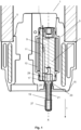
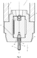
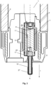
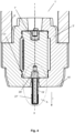
- The following schematic drawings show aspects of the invention for improving the understanding of the invention in connection with some exemplary illustrations, wherein
- Figures 1 and 2
- show schematic sectional views of a sampler according to a first embodiment of the invention;
- Figures 3 and 4
- show schematic sectional views of a sampler according to a second embodiment of the invention; and
- Figure 5
- shows detail 'A' of
figure 4 . -
Figure 1 and2 show schematic sectional views of asampler 1 for taking samples from a molten metal bath according to a first embodiment of the invention. Thesampler 1 is suitable for immersion in and sampling of molten steel. The shownsampler 1 comprises a measuringhead 3 which can be made of resin bonded silica sand. The measuringhead 3 is supported on acarrier tube 5, which can be a paper carrier tube. In use, a probe holder or lance (not shown) is preferably inserted into the interior volume of thecarrier tube 5 to provide the mechanical action necessary to submerse the measuringhead 3 below the surface of a bath of molten metal (not shown) in the immersion direction I. - The measuring
head 3 comprises asample chamber assembly 7 for collection and retrieval of a sample of molten metal. Thesample chamber assembly 7 as shown is a two-part sample chamber composed of ahousing 9 and coverplate 11. Thehousing 9 is preferably formed of one or more materials which are good thermal and electrical conductors, such as, but not limited to, aluminum, copper and other metals having similar thermal and electrical conductivity properties for being electrically coupled to the retrieved metal sample. The housing and thecover plate sample chamber assembly 7 can be held together by aclamp 13 with a compression force sufficient to resist a tendency of the twoparts sample chamber 7 assembly to separate due to the force of molten metal flowing into and filling thesample chamber assembly 7. Theclamp 13 can be a metal clamp. -
Figures 1 and2 also show the measuringhead 3 having a first end and an opposing second end. The first end of the measuringhead 5 corresponds to animmersion end 15 of the measuringhead 5. The second end of the measuringhead 3 is configured to face the lance or probe holder. Also, thesample chamber assembly 7 has a first end and an opposing second end. The first end of thesample chamber assembly 7 corresponds to animmersion end 17 of thesample chamber assembly 7. It will be understood by those skilled in the art that the phrase "immersion end" means the end of the body which is first immersed into molten metal. The first end of thesample chamber assembly 7 is attached to aninflow conduit 19, where the inflow conduit is received at an opening in thehousing 9. Theinflow conduit 19 enables the flow of molten metal from the molten metal bath into thesample chamber assembly 7. Thus, molten metal is introduced into thesample chamber assembly 7 in the immersion direction I parallel to the central axis X of the sample cavity. Theinflow conduit 7 can be made of a quartz material, more preferably a fused quartz material. -
Figures 1 and2 also show thede-oxidant material 21 which can be aluminum arranged along the central axis X of theinflow conduit 7. It can also be seen that a part of thede-oxidant material 21 is arranged near the second end of theinflow conduit 19 inside the measuringhead 3. - Also shown in
figures 1 and2 are first coupling means 23 at theinflow conduit 19 which can be realized as recesses or protrusions in the material of theinflow conduit 19. Thede-oxidant material 21 comprises second coupling means 25 which can be realized as protrusions that interact with the corresponding recesses of the first coupling means 23 or vice versa. Due to the shown coupling means 23, 25 infigures 1 and2 , thede-oxidant material 21 can be reliably hold along the central axis X in the entry path of thesample chamber assembly 9 and is, thus, capable to withstand the force of the purging gas while purging, and the force of the liquid steel entering the unit during the filling. - Also,
figures 1 and2 show acap 27 arranged at the first end of theinflow conduit 19. When the first end of the inflow conduit is submerged in molten metal, thecap 27 will melt, and molten metal can flow through theinflow conduit 19. Further shown infigures 1 and2 is ametal bushing 29 that couples theinflow conduit 19 to thehousing 9 ofsample chamber assembly 7. However, themetal bushing 29 is merely optional for this embodiment. Theinflow conduit 19 can be also attached to thehousing 9 by means of a glue or a cement. -
Figures 3 and4 show schematic sectional views of a sampler 1' according to a second embodiment of the invention. - The sampler 1' is suitable for immersion in and sampling of molten steel. The shown sampler 1' comprises a measuring head 3' which can be made of resin bonded silica sand. The measuring head 3' is supported on a carrier tube 5', which can be a paper carrier tube. In use, a probe holder or lance (not shown) is preferably inserted into the interior volume of the carrier tube 5' to provide the mechanical action necessary to submerse the measuring head 3' below the surface of a bath of molten metal (not shown) in the immersion direction I.
- The measuring head 3' comprises a sample chamber assembly 7' for collection and retrieval of a sample of molten metal. The sample chamber assembly 7' as shown is a two-part sample chamber composed of a housing 9' and cover plate 11'. The housing 9' is preferably formed of one or more materials which are good thermal and electrical conductors, such as, but not limited to, aluminum, copper and other metals having similar thermal and electrical conductivity properties for being electrically coupled to the retrieved metal sample. The housing and the cover plate 9', 11' of the sample chamber assembly 7' can be held together by a clamp 13' with a compression force sufficient to resist a tendency of the two parts 9', 11' of the sample chamber 7' assembly to separate due to the force of molten metal flowing into and filling the sample chamber assembly 7'. The clamp 13' can be a metal clamp.
-
Figures 3 and4 also show the measuring head 3' having a first end and an opposing second end. The first end of the measuring head 5' corresponds to an immersion end 15'. The second end of the measuring head 3' is configured to face the lance or probe holder. Also, the sample chamber assembly 7' has a first end and an opposing second end. The first end of the sample chamber assembly 7' corresponds to an immersion end 17'. It will be understood by those skilled in the art that the phrase "immersion end" means the end of the body which is first immersed into molten metal. The first end of the sample chamber assembly 7' is attached to an inflow conduit 19', where the inflow conduit is received at an opening in thehousing 9. The inflow conduit 19' enables the flow of molten metal from the molten metal bath into thesample chamber assembly 7. Thus, molten metal is introduced into the sample chamber assembly 7' against the immersion direction I parallel to the longitudinal axis X of the sample cavity. The inflow conduit 7' can be made of a quartz material, more preferably a fused quartz material. - As shown in
Figures 3 and4 , the sampler 1' also comprises a metal bushing 29' which can comprises an aluminum material. The metal bushing 29' can have a length of 10 to 40 mm, an inner diameter of 4 mm, and an outer diameter of 6 mm. In the shown embodiment, the metal bushing 29' is pressed into the housing 9' of the sample chamber assembly 7' for coupling the inflow conduit 19' to the sample chamber assembly 7'. -
Figure 5 shows detail 'A' offigure 4 . As shown, the metal bushing 29' reaches from the sample chamber assembly 7' all the way down to the first end of the inflow conduit 19', and thereby surrounding the inflow conduit 19'. Also, it can be seen that the metal bushing 29' has at least two different wall thicknesses and/or diameters along its length. -
- 1, 1' Sampler
- 3, 3' Measuring Head
- 5. 5' Carrier Tube
- 7, 7' Sample Chamber Assembly
- 9, 9' Housing
- 11, 11' Cover Plate
- 13, 13' Clamp
- 15, 15' Immersion End of Measuring Head
- 17, 17' Immersion End of Sample Chamber
- 19, 19' Inflow Conduit
- 21 De-Oxidant Material
- 23 First Coupling Means
- 25 Second Coupling Means
- 27, 27' Cap
- 29, 29' Metal Bushing
- A Detail
- I Immersion Direction
- X Central Axis
Claims (8)
- A sampler (1, 1') for taking samples from a molten metal bath, particularly a molten steel bath, the sampler (1, 1') comprising:a carrier tube (5, 5') having an immersion end;a sample chamber assembly (7, 7') arranged on the immersion end of the carrier tube (5, 5'), the sample chamber assembly (7, 7') comprising a cover plate (11, 11') and a housing (9, 9'), wherein the housing (9, 9') comprises an immersion end having an opening;an inflow conduit (19, 19') having a first end for receiving molten metal and a second end, opposite the first end, wherein the second end is in communication with the opening, wherein the opening is configured to receive the molten metal from the inflow conduit;a measuring head (3, 3'), wherein the sample chamber and the second end of the inflow conduit are at least partly arranged in the measuring head (3, 3'); anda metal bushing (29, 29'), wherein the metal bushing (29, 29') couples the inflow conduit to the sample chamber.
- The sampler (1, 1') according to claim 1, wherein the metal bushing (29, 29') is adapted to reach from the sample chamber assembly (7, 7') to the first end of the inflow conduit (19, 19').
- The sampler (1, 1') according to claim 1 or 2, wherein the metal bushing (29, 29') has at least two different wall thicknesses and/or diameters along its length.
- The sampler (1, 1') according to any of the preceding claims, wherein the metal bushing (29, 29') comprises an aluminum material, and/or wherein the inflow conduit (19, 19') comprises a quartz material, preferably a fused quartz material.
- The sampler (1, 1') according to any of the preceding claims, wherein the metal bushing (29, 29') has a length of 10 to 40 mm, an inner diameter of 4 mm, and an outer diameter of 6 mm.
- The sampler (1, 1') according to any of the preceding claims, wherein the metal bushing (29, 29') is pressed into the sample chamber for coupling the inflow conduit (19, 19') to the sample chamber.
- The sampler (1, 1') according to any of the preceding claims, wherein the sampler comprises a protection cap (27, 27') attached to the first end of the inflow conduit (19, 19').
- The sampler (1, 1') according to any of the preceding claims, wherein the bushing (29, 29') comprises grooves on an outer surface of the bushing (29, 29') to minimize heat transfer to the sample chamber assembly (7, 7').
Priority Applications (3)
| Application Number | Priority Date | Filing Date | Title |
|---|---|---|---|
| EP23170346.3A EP4235172B1 (en) | 2018-06-12 | 2018-06-12 | Molten metal samplers for high and low oxygen applications |
| PL23170346.3T PL4235172T3 (en) | 2018-06-12 | 2018-06-12 | Molten metal samplers for high and low oxygen applications |
| ES23170346T ES3015530T3 (en) | 2018-06-12 | 2018-06-12 | Molten metal samplers for high and low oxygen applications |
Applications Claiming Priority (2)
| Application Number | Priority Date | Filing Date | Title |
|---|---|---|---|
| EP23170346.3A EP4235172B1 (en) | 2018-06-12 | 2018-06-12 | Molten metal samplers for high and low oxygen applications |
| EP18177317.7A EP3581914B1 (en) | 2018-06-12 | 2018-06-12 | Molten metal samplers for high and low oxygen applications |
Related Parent Applications (2)
| Application Number | Title | Priority Date | Filing Date |
|---|---|---|---|
| EP18177317.7A Division EP3581914B1 (en) | 2018-06-12 | 2018-06-12 | Molten metal samplers for high and low oxygen applications |
| EP18177317.7A Division-Into EP3581914B1 (en) | 2018-06-12 | 2018-06-12 | Molten metal samplers for high and low oxygen applications |
Publications (3)
| Publication Number | Publication Date |
|---|---|
| EP4235172A2 EP4235172A2 (en) | 2023-08-30 |
| EP4235172A3 EP4235172A3 (en) | 2023-10-11 |
| EP4235172B1 true EP4235172B1 (en) | 2025-01-29 |
Family
ID=62748710
Family Applications (2)
| Application Number | Title | Priority Date | Filing Date |
|---|---|---|---|
| EP18177317.7A Active EP3581914B1 (en) | 2018-06-12 | 2018-06-12 | Molten metal samplers for high and low oxygen applications |
| EP23170346.3A Active EP4235172B1 (en) | 2018-06-12 | 2018-06-12 | Molten metal samplers for high and low oxygen applications |
Family Applications Before (1)
| Application Number | Title | Priority Date | Filing Date |
|---|---|---|---|
| EP18177317.7A Active EP3581914B1 (en) | 2018-06-12 | 2018-06-12 | Molten metal samplers for high and low oxygen applications |
Country Status (12)
| Country | Link |
|---|---|
| US (2) | US11592363B2 (en) |
| EP (2) | EP3581914B1 (en) |
| JP (2) | JP6912514B2 (en) |
| KR (2) | KR102284631B1 (en) |
| CN (2) | CN115979718A (en) |
| AU (2) | AU2019202946B2 (en) |
| ES (2) | ES3015530T3 (en) |
| PL (2) | PL4235172T3 (en) |
| RU (1) | RU2712618C1 (en) |
| TW (1) | TWI757601B (en) |
| UA (2) | UA128490C2 (en) |
| ZA (1) | ZA201903141B (en) |
Families Citing this family (4)
| Publication number | Priority date | Publication date | Assignee | Title |
|---|---|---|---|---|
| KR102383120B1 (en) * | 2019-12-27 | 2022-04-06 | 우진 일렉트로나이트㈜ | Disc shaped sample chamber and probe including the same |
| EP4215896B1 (en) | 2022-01-21 | 2025-07-16 | Heraeus Electro-Nite International N.V. | Improved sample chamber for molten metal |
| EP4227669A1 (en) | 2022-02-15 | 2023-08-16 | Heraeus Electro-Nite International N.V. | Exchangeable spark unit and calibration method |
| EP4610620A1 (en) * | 2024-03-01 | 2025-09-03 | Heraeus Electro-Nite International N.V. | Sample unit for a sampling system and method for taking samples from molten aluminum in a primary aluminum producing facility |
Family Cites Families (44)
| Publication number | Priority date | Publication date | Assignee | Title |
|---|---|---|---|---|
| BE624414A (en) * | 1961-11-14 | |||
| CH409469A (en) * | 1963-12-20 | 1966-03-15 | Heinrich Dr Feichtinger | Method and device for taking samples from melts for the purpose of detecting the gases released during solidification |
| FR1530322A (en) * | 1967-07-06 | 1968-06-21 | Leeds & Northrup Co | Immersion molten metal sampling apparatus |
| US3646816A (en) | 1970-07-22 | 1972-03-07 | Leeds & Northrup Co | Immersion molten metal sampler |
| GB1508974A (en) * | 1974-03-20 | 1978-04-26 | Collins R | Molten metal samplers |
| GB1456353A (en) * | 1974-05-06 | 1976-11-24 | Leeds & Northrup Co | Immersion sampler for molten material |
| FR2282633A2 (en) * | 1974-08-21 | 1976-03-19 | Decolletage Et Const Meca Ste | Sampling molten metals, esp steel - to form a cast test bar suitable for rapid quantitative analysis |
| US3974698A (en) * | 1975-01-24 | 1976-08-17 | Lukens Steel Company | Molten metal sampler for electroslag refining process |
| US4002072A (en) * | 1975-03-31 | 1977-01-11 | Collins William J | Device and method of obtaining a sample of liquid |
| US4166391A (en) * | 1975-04-07 | 1979-09-04 | Mcdevitt Robert F | Molten metal sampler |
| US3974638A (en) * | 1975-09-04 | 1976-08-17 | Haber Terry M | Hourglass watch |
| US4037478A (en) * | 1976-09-15 | 1977-07-26 | Electro-Nite Co. | Device for collecting samples of molten metal |
| US4077264A (en) * | 1976-09-07 | 1978-03-07 | Mcdevitt Robert F | Connectors for molten metal samplers |
| FR2406822A1 (en) * | 1977-10-19 | 1979-05-18 | Lorraine Decolletage | Sampling effervescent molten metal, esp. steel - using mould in end of tubular envelope of dehydrated cardboard, with tube allowing mould to fill without forming cavities |
| FR2421373A1 (en) | 1978-03-30 | 1979-10-26 | Electro Nite | BLOWING VENT FOR FUSION METAL SAMPLE TAKING DEVICE |
| US4237734A (en) * | 1979-04-16 | 1980-12-09 | Mcdevitt Robert F | Device for obtaining a sample of liquid |
| US4361053A (en) * | 1980-11-13 | 1982-11-30 | Electro-Nite Co. | Molten metal bath temperature sensor and sampler |
| US4401389A (en) | 1981-01-24 | 1983-08-30 | Electro-Nite Co. | Measuring probe for taking a sample from a metal bath and for measuring the bath temperatures |
| US4453424A (en) * | 1981-04-29 | 1984-06-12 | Haly, Inc. | Molten metal sampler |
| DE3203505A1 (en) * | 1982-02-02 | 1983-08-04 | Minkon Sampler Technik GmbH, 4006 Erkrath | MELT SAMPLING FORM FOR ANALYZING PURPOSES |
| IT1151186B (en) * | 1982-05-20 | 1986-12-17 | Sidermes Srl | SAMPLER DEVICE FOR TAKING A MOLT METAL SAMPLE BY DETERMINING THE TEMPERATURE OF THE MELTING BATH |
| US4569237A (en) * | 1984-04-16 | 1986-02-11 | Electro-Nite Co. | Method of sampling molten metal |
| JP2745356B2 (en) * | 1992-05-15 | 1998-04-28 | 川惣電機工業 株式会社 | Equipment for collecting molten metal samples |
| DE4303687C1 (en) * | 1993-02-09 | 1994-06-30 | Heraeus Electro Nite Int | Sampler for molten metal |
| DE4303688C3 (en) * | 1993-02-09 | 2000-06-15 | Heraeus Electro Nite Int | Sampler for molten metal |
| US5448923A (en) * | 1994-09-27 | 1995-09-12 | Haly Inc. | Scored metal slag covers for molten sampler intake portals |
| US5577841A (en) * | 1995-02-06 | 1996-11-26 | Heraeus Electro-Nite International N.V. | Molten metal immersion probe |
| JP3902512B2 (en) * | 2002-06-07 | 2007-04-11 | 新日本製鐵株式会社 | Metal sample rapid sampling sampler and rapid sampling method using the same |
| DE10360625B3 (en) * | 2003-12-19 | 2005-01-13 | Heraeus Electro-Nite International N.V. | Sampler for molten metal comprises sample chamber mounted in support tube with inlet section which carries quartz glass inlet tube which curves in at both ends |
| DE102004032561B3 (en) * | 2004-07-05 | 2006-02-09 | Heraeus Electro-Nite International N.V. | Container for molten metal and use of the container |
| JP4499019B2 (en) | 2005-10-27 | 2010-07-07 | 株式会社神戸製鋼所 | Composite sampler for collecting molten steel |
| DE102005060492B3 (en) * | 2005-12-15 | 2007-05-24 | Heraeus Electro-Nite International N.V. | Measuring probe for use in molten metals and slag has measuring head with sensors and signal leads guided through separate ducts to connect with separate contact members at end remote from immersion end |
| DE102007063673B4 (en) * | 2007-07-10 | 2018-02-08 | Heraeus Electro-Nite International N.V. | measurement methods |
| RU2397471C1 (en) * | 2009-03-18 | 2010-08-20 | ООО "Нординкрафт-Сенсор" | Device for chemical analysis of molten mass and device for realising said method |
| DE102011121183B4 (en) * | 2011-05-18 | 2014-02-27 | Heraeus Electro-Nite International N.V. | Sampler for sampling from melts with a melting point greater than 600 ° C and method for sampling |
| DE102013224565A1 (en) * | 2013-04-30 | 2014-10-30 | Heraeus Electro-Nite International N.V. | Sampler and method for sampling |
| US9958405B2 (en) * | 2015-01-21 | 2018-05-01 | Heraeus Electro-Nite International N.V. | Reverse filling carbon and temperature drop-in sensor |
| EP3130906A1 (en) * | 2015-08-12 | 2017-02-15 | Heraeus Electro-Nite International N.V. | Slag cap |
| CN105842008A (en) * | 2016-03-21 | 2016-08-10 | 贺利氏电子耐特国际股份公司 | Immersed type measuring probe for molten metal |
| EP3293505B1 (en) * | 2016-09-13 | 2018-11-14 | Heraeus Electro-Nite International N.V. | Immersion device for slag sample collection |
| EP3336511B1 (en) * | 2016-12-13 | 2019-06-12 | Heraeus Electro-Nite International N.V. | Direct analysis sampler |
| EP3336512B1 (en) | 2016-12-13 | 2019-02-13 | Heraeus Electro-Nite International N.V. | Direct analysis sampler with heat sink |
| PL3336513T3 (en) | 2016-12-13 | 2021-09-06 | Heraeus Electro-Nite International N.V. | Sampler for molten metal |
| EP3336514B1 (en) | 2016-12-13 | 2023-05-31 | Heraeus Electro-Nite International N.V. | Direct analysis sampler |
-
2018
- 2018-06-12 EP EP18177317.7A patent/EP3581914B1/en active Active
- 2018-06-12 ES ES23170346T patent/ES3015530T3/en active Active
- 2018-06-12 ES ES18177317T patent/ES2950447T3/en active Active
- 2018-06-12 EP EP23170346.3A patent/EP4235172B1/en active Active
- 2018-06-12 PL PL23170346.3T patent/PL4235172T3/en unknown
- 2018-06-12 PL PL18177317.7T patent/PL3581914T3/en unknown
-
2019
- 2019-04-26 AU AU2019202946A patent/AU2019202946B2/en active Active
- 2019-05-07 TW TW108115710A patent/TWI757601B/en active
- 2019-05-20 ZA ZA2019/03141A patent/ZA201903141B/en unknown
- 2019-05-21 JP JP2019095575A patent/JP6912514B2/en active Active
- 2019-06-05 CN CN202310209883.6A patent/CN115979718A/en active Pending
- 2019-06-05 CN CN201910488144.9A patent/CN110595832B/en active Active
- 2019-06-07 US US16/434,901 patent/US11592363B2/en active Active
- 2019-06-10 RU RU2019117941A patent/RU2712618C1/en active
- 2019-06-10 UA UAA202105747A patent/UA128490C2/en unknown
- 2019-06-10 UA UAA201906409A patent/UA124974C2/en unknown
- 2019-06-11 KR KR1020190068707A patent/KR102284631B1/en active Active
-
2020
- 2020-06-30 AU AU2020204374A patent/AU2020204374B2/en active Active
-
2021
- 2021-05-27 KR KR1020210068240A patent/KR102445005B1/en active Active
- 2021-07-06 JP JP2021112331A patent/JP2021183968A/en active Pending
-
2023
- 2023-01-27 US US18/160,436 patent/US11988581B2/en active Active
Also Published As
Similar Documents
| Publication | Publication Date | Title |
|---|---|---|
| US11988581B2 (en) | Molten metal samplers for high and low oxygen applications | |
| JP6723978B2 (en) | Direct analysis sampler with heat sink | |
| US11660594B2 (en) | Molten metal sampler | |
| EP4215896B1 (en) | Improved sample chamber for molten metal | |
| BR122024010857A2 (en) | MOLTEN METAL SAMPLERS FOR HIGH AND LOW OXYGEN CONCENTRATION APPLICATIONS | |
| BR102019011481B1 (en) | MOLTEN METAL SAMPLERS FOR HIGH AND LOW OXYGEN CONCENTRATION APPLICATIONS | |
| BR122024010857B1 (en) | MOLTEN METAL SAMPLERS FOR HIGH AND LOW OXYGEN CONCENTRATION APPLICATIONS | |
| EP4610620A1 (en) | Sample unit for a sampling system and method for taking samples from molten aluminum in a primary aluminum producing facility |
Legal Events
| Date | Code | Title | Description |
|---|---|---|---|
| PUAI | Public reference made under article 153(3) epc to a published international application that has entered the european phase |
Free format text: ORIGINAL CODE: 0009012 |
|
| STAA | Information on the status of an ep patent application or granted ep patent |
Free format text: STATUS: REQUEST FOR EXAMINATION WAS MADE |
|
| 17P | Request for examination filed |
Effective date: 20230427 |
|
| AC | Divisional application: reference to earlier application |
Ref document number: 3581914 Country of ref document: EP Kind code of ref document: P |
|
| AK | Designated contracting states |
Kind code of ref document: A2 Designated state(s): AL AT BE BG CH CY CZ DE DK EE ES FI FR GB GR HR HU IE IS IT LI LT LU LV MC MK MT NL NO PL PT RO RS SE SI SK SM TR |
|
| REG | Reference to a national code |
Ref country code: DE Free format text: PREVIOUS MAIN CLASS: G01N0033200000 Ref legal event code: R079 Ref document number: 602018078949 Country of ref document: DE Ipc: G01N0001120000 |
|
| PUAL | Search report despatched |
Free format text: ORIGINAL CODE: 0009013 |
|
| AK | Designated contracting states |
Kind code of ref document: A3 Designated state(s): AL AT BE BG CH CY CZ DE DK EE ES FI FR GB GR HR HU IE IS IT LI LT LU LV MC MK MT NL NO PL PT RO RS SE SI SK SM TR |
|
| RIC1 | Information provided on ipc code assigned before grant |
Ipc: G01N 33/20 20190101ALN20230904BHEP Ipc: G01N 1/12 20060101AFI20230904BHEP |
|
| GRAP | Despatch of communication of intention to grant a patent |
Free format text: ORIGINAL CODE: EPIDOSNIGR1 |
|
| STAA | Information on the status of an ep patent application or granted ep patent |
Free format text: STATUS: GRANT OF PATENT IS INTENDED |
|
| RIC1 | Information provided on ipc code assigned before grant |
Ipc: G01N 33/20 20190101ALN20240711BHEP Ipc: G01N 1/12 20060101AFI20240711BHEP |
|
| INTG | Intention to grant announced |
Effective date: 20240724 |
|
| GRAS | Grant fee paid |
Free format text: ORIGINAL CODE: EPIDOSNIGR3 |
|
| GRAA | (expected) grant |
Free format text: ORIGINAL CODE: 0009210 |
|
| STAA | Information on the status of an ep patent application or granted ep patent |
Free format text: STATUS: THE PATENT HAS BEEN GRANTED |
|
| AC | Divisional application: reference to earlier application |
Ref document number: 3581914 Country of ref document: EP Kind code of ref document: P |
|
| AK | Designated contracting states |
Kind code of ref document: B1 Designated state(s): AL AT BE BG CH CY CZ DE DK EE ES FI FR GB GR HR HU IE IS IT LI LT LU LV MC MK MT NL NO PL PT RO RS SE SI SK SM TR |
|
| REG | Reference to a national code |
Ref country code: GB Ref legal event code: FG4D |
|
| REG | Reference to a national code |
Ref country code: CH Ref legal event code: EP |
|
| REG | Reference to a national code |
Ref country code: DE Ref legal event code: R096 Ref document number: 602018078949 Country of ref document: DE |
|
| REG | Reference to a national code |
Ref country code: SE Ref legal event code: TRGR |
|
| REG | Reference to a national code |
Ref country code: IE Ref legal event code: FG4D Ref country code: NL Ref legal event code: FP |
|
| P01 | Opt-out of the competence of the unified patent court (upc) registered |
Free format text: CASE NUMBER: APP_8893/2025 Effective date: 20250221 |
|
| REG | Reference to a national code |
Ref country code: ES Ref legal event code: FG2A Ref document number: 3015530 Country of ref document: ES Kind code of ref document: T3 Effective date: 20250506 |
|
| PG25 | Lapsed in a contracting state [announced via postgrant information from national office to epo] |
Ref country code: RS Free format text: LAPSE BECAUSE OF FAILURE TO SUBMIT A TRANSLATION OF THE DESCRIPTION OR TO PAY THE FEE WITHIN THE PRESCRIBED TIME-LIMIT Effective date: 20250429 |
|
| PG25 | Lapsed in a contracting state [announced via postgrant information from national office to epo] |
Ref country code: FI Free format text: LAPSE BECAUSE OF FAILURE TO SUBMIT A TRANSLATION OF THE DESCRIPTION OR TO PAY THE FEE WITHIN THE PRESCRIBED TIME-LIMIT Effective date: 20250129 |
|
| PGFP | Annual fee paid to national office [announced via postgrant information from national office to epo] |
Ref country code: PL Payment date: 20250522 Year of fee payment: 8 Ref country code: DE Payment date: 20250618 Year of fee payment: 8 |
|
| PGFP | Annual fee paid to national office [announced via postgrant information from national office to epo] |
Ref country code: GB Payment date: 20250618 Year of fee payment: 8 |
|
| REG | Reference to a national code |
Ref country code: LT Ref legal event code: MG9D |
|
| PG25 | Lapsed in a contracting state [announced via postgrant information from national office to epo] |
Ref country code: NO Free format text: LAPSE BECAUSE OF FAILURE TO SUBMIT A TRANSLATION OF THE DESCRIPTION OR TO PAY THE FEE WITHIN THE PRESCRIBED TIME-LIMIT Effective date: 20250429 Ref country code: IS Free format text: LAPSE BECAUSE OF FAILURE TO SUBMIT A TRANSLATION OF THE DESCRIPTION OR TO PAY THE FEE WITHIN THE PRESCRIBED TIME-LIMIT Effective date: 20250529 |
|
| PGFP | Annual fee paid to national office [announced via postgrant information from national office to epo] |
Ref country code: NL Payment date: 20250618 Year of fee payment: 8 |
|
| PG25 | Lapsed in a contracting state [announced via postgrant information from national office to epo] |
Ref country code: HR Free format text: LAPSE BECAUSE OF FAILURE TO SUBMIT A TRANSLATION OF THE DESCRIPTION OR TO PAY THE FEE WITHIN THE PRESCRIBED TIME-LIMIT Effective date: 20250129 |
|
| PG25 | Lapsed in a contracting state [announced via postgrant information from national office to epo] |
Ref country code: PT Free format text: LAPSE BECAUSE OF FAILURE TO SUBMIT A TRANSLATION OF THE DESCRIPTION OR TO PAY THE FEE WITHIN THE PRESCRIBED TIME-LIMIT Effective date: 20250529 Ref country code: LV Free format text: LAPSE BECAUSE OF FAILURE TO SUBMIT A TRANSLATION OF THE DESCRIPTION OR TO PAY THE FEE WITHIN THE PRESCRIBED TIME-LIMIT Effective date: 20250129 |
|
| PGFP | Annual fee paid to national office [announced via postgrant information from national office to epo] |
Ref country code: FR Payment date: 20250627 Year of fee payment: 8 |
|
| PG25 | Lapsed in a contracting state [announced via postgrant information from national office to epo] |
Ref country code: GR Free format text: LAPSE BECAUSE OF FAILURE TO SUBMIT A TRANSLATION OF THE DESCRIPTION OR TO PAY THE FEE WITHIN THE PRESCRIBED TIME-LIMIT Effective date: 20250430 Ref country code: BG Free format text: LAPSE BECAUSE OF FAILURE TO SUBMIT A TRANSLATION OF THE DESCRIPTION OR TO PAY THE FEE WITHIN THE PRESCRIBED TIME-LIMIT Effective date: 20250129 |
|
| PGFP | Annual fee paid to national office [announced via postgrant information from national office to epo] |
Ref country code: AT Payment date: 20250620 Year of fee payment: 8 |
|
| PGFP | Annual fee paid to national office [announced via postgrant information from national office to epo] |
Ref country code: TR Payment date: 20250603 Year of fee payment: 8 |
|
| PGFP | Annual fee paid to national office [announced via postgrant information from national office to epo] |
Ref country code: SE Payment date: 20250618 Year of fee payment: 8 |
|
| PG25 | Lapsed in a contracting state [announced via postgrant information from national office to epo] |
Ref country code: SM Free format text: LAPSE BECAUSE OF FAILURE TO SUBMIT A TRANSLATION OF THE DESCRIPTION OR TO PAY THE FEE WITHIN THE PRESCRIBED TIME-LIMIT Effective date: 20250129 |
|
| PGFP | Annual fee paid to national office [announced via postgrant information from national office to epo] |
Ref country code: ES Payment date: 20250731 Year of fee payment: 8 |
|
| PG25 | Lapsed in a contracting state [announced via postgrant information from national office to epo] |
Ref country code: DK Free format text: LAPSE BECAUSE OF FAILURE TO SUBMIT A TRANSLATION OF THE DESCRIPTION OR TO PAY THE FEE WITHIN THE PRESCRIBED TIME-LIMIT Effective date: 20250129 |
|
| PGFP | Annual fee paid to national office [announced via postgrant information from national office to epo] |
Ref country code: IT Payment date: 20250624 Year of fee payment: 8 |
|
| PG25 | Lapsed in a contracting state [announced via postgrant information from national office to epo] |
Ref country code: EE Free format text: LAPSE BECAUSE OF FAILURE TO SUBMIT A TRANSLATION OF THE DESCRIPTION OR TO PAY THE FEE WITHIN THE PRESCRIBED TIME-LIMIT Effective date: 20250129 Ref country code: CZ Free format text: LAPSE BECAUSE OF FAILURE TO SUBMIT A TRANSLATION OF THE DESCRIPTION OR TO PAY THE FEE WITHIN THE PRESCRIBED TIME-LIMIT Effective date: 20250129 |
|
| PG25 | Lapsed in a contracting state [announced via postgrant information from national office to epo] |
Ref country code: RO Free format text: LAPSE BECAUSE OF FAILURE TO SUBMIT A TRANSLATION OF THE DESCRIPTION OR TO PAY THE FEE WITHIN THE PRESCRIBED TIME-LIMIT Effective date: 20250129 |
|
| PG25 | Lapsed in a contracting state [announced via postgrant information from national office to epo] |
Ref country code: SK Free format text: LAPSE BECAUSE OF FAILURE TO SUBMIT A TRANSLATION OF THE DESCRIPTION OR TO PAY THE FEE WITHIN THE PRESCRIBED TIME-LIMIT Effective date: 20250129 |
|
| REG | Reference to a national code |
Ref country code: DE Ref legal event code: R097 Ref document number: 602018078949 Country of ref document: DE |
|
| PLBE | No opposition filed within time limit |
Free format text: ORIGINAL CODE: 0009261 |
|
| STAA | Information on the status of an ep patent application or granted ep patent |
Free format text: STATUS: NO OPPOSITION FILED WITHIN TIME LIMIT |
|
| REG | Reference to a national code |
Ref country code: CH Ref legal event code: L10 Free format text: ST27 STATUS EVENT CODE: U-0-0-L10-L00 (AS PROVIDED BY THE NATIONAL OFFICE) Effective date: 20251210 |
|
| 26N | No opposition filed |
Effective date: 20251030 |
|
| REG | Reference to a national code |
Ref country code: CH Ref legal event code: H13 Free format text: ST27 STATUS EVENT CODE: U-0-0-H10-H13 (AS PROVIDED BY THE NATIONAL OFFICE) Effective date: 20260127 |
|
| PG25 | Lapsed in a contracting state [announced via postgrant information from national office to epo] |
Ref country code: MC Free format text: LAPSE BECAUSE OF FAILURE TO SUBMIT A TRANSLATION OF THE DESCRIPTION OR TO PAY THE FEE WITHIN THE PRESCRIBED TIME-LIMIT Effective date: 20250129 |
|
| PG25 | Lapsed in a contracting state [announced via postgrant information from national office to epo] |
Ref country code: LU Free format text: LAPSE BECAUSE OF NON-PAYMENT OF DUE FEES Effective date: 20250612 |
|
| REG | Reference to a national code |
Ref country code: BE Ref legal event code: MM Effective date: 20250630 |
|
| PG25 | Lapsed in a contracting state [announced via postgrant information from national office to epo] |
Ref country code: IE Free format text: LAPSE BECAUSE OF NON-PAYMENT OF DUE FEES Effective date: 20250612 |
|
| PG25 | Lapsed in a contracting state [announced via postgrant information from national office to epo] |
Ref country code: BE Free format text: LAPSE BECAUSE OF NON-PAYMENT OF DUE FEES Effective date: 20250630 |
|
| PG25 | Lapsed in a contracting state [announced via postgrant information from national office to epo] |
Ref country code: CH Free format text: LAPSE BECAUSE OF NON-PAYMENT OF DUE FEES Effective date: 20250630 |