EP4235045A2 - A roof window system comprising a ventilation assembly with an exhaust device and method of operating a ventilation assembly of such a roof window system - Google Patents
A roof window system comprising a ventilation assembly with an exhaust device and method of operating a ventilation assembly of such a roof window system Download PDFInfo
- Publication number
- EP4235045A2 EP4235045A2 EP23179221.9A EP23179221A EP4235045A2 EP 4235045 A2 EP4235045 A2 EP 4235045A2 EP 23179221 A EP23179221 A EP 23179221A EP 4235045 A2 EP4235045 A2 EP 4235045A2
- Authority
- EP
- European Patent Office
- Prior art keywords
- ventilation
- roof window
- channel
- air
- inside air
- Prior art date
- Legal status (The legal status is an assumption and is not a legal conclusion. Google has not performed a legal analysis and makes no representation as to the accuracy of the status listed.)
- Pending
Links
- 238000009423 ventilation Methods 0.000 title claims abstract description 185
- 238000000034 method Methods 0.000 title claims description 12
- 239000003570 air Substances 0.000 claims abstract description 121
- 239000012530 fluid Substances 0.000 claims abstract description 19
- 239000012080 ambient air Substances 0.000 claims abstract description 14
- 239000000126 substance Substances 0.000 claims description 4
- 230000003213 activating effect Effects 0.000 claims description 2
- 238000009420 retrofitting Methods 0.000 claims description 2
- 238000009434 installation Methods 0.000 description 10
- 230000000712 assembly Effects 0.000 description 3
- 238000000429 assembly Methods 0.000 description 3
- 238000000605 extraction Methods 0.000 description 2
- 239000000463 material Substances 0.000 description 2
- 229920002635 polyurethane Polymers 0.000 description 2
- 239000004814 polyurethane Substances 0.000 description 2
- 230000004888 barrier function Effects 0.000 description 1
- 238000005253 cladding Methods 0.000 description 1
- 230000001419 dependent effect Effects 0.000 description 1
- 239000000284 extract Substances 0.000 description 1
- 238000005399 mechanical ventilation Methods 0.000 description 1
- 238000004513 sizing Methods 0.000 description 1
Images


Classifications
-
- E—FIXED CONSTRUCTIONS
- E04—BUILDING
- E04D—ROOF COVERINGS; SKY-LIGHTS; GUTTERS; ROOF-WORKING TOOLS
- E04D13/00—Special arrangements or devices in connection with roof coverings; Protection against birds; Roof drainage; Sky-lights
- E04D13/03—Sky-lights; Domes; Ventilating sky-lights
- E04D13/0325—Sky-lights; Domes; Ventilating sky-lights provided with ventilating means
-
- E—FIXED CONSTRUCTIONS
- E06—DOORS, WINDOWS, SHUTTERS, OR ROLLER BLINDS IN GENERAL; LADDERS
- E06B—FIXED OR MOVABLE CLOSURES FOR OPENINGS IN BUILDINGS, VEHICLES, FENCES OR LIKE ENCLOSURES IN GENERAL, e.g. DOORS, WINDOWS, BLINDS, GATES
- E06B7/00—Special arrangements or measures in connection with doors or windows
- E06B7/02—Special arrangements or measures in connection with doors or windows for providing ventilation, e.g. through double windows; Arrangement of ventilation roses
- E06B7/10—Special arrangements or measures in connection with doors or windows for providing ventilation, e.g. through double windows; Arrangement of ventilation roses by special construction of the frame members
-
- E—FIXED CONSTRUCTIONS
- E04—BUILDING
- E04D—ROOF COVERINGS; SKY-LIGHTS; GUTTERS; ROOF-WORKING TOOLS
- E04D13/00—Special arrangements or devices in connection with roof coverings; Protection against birds; Roof drainage; Sky-lights
- E04D13/03—Sky-lights; Domes; Ventilating sky-lights
-
- F—MECHANICAL ENGINEERING; LIGHTING; HEATING; WEAPONS; BLASTING
- F24—HEATING; RANGES; VENTILATING
- F24F—AIR-CONDITIONING; AIR-HUMIDIFICATION; VENTILATION; USE OF AIR CURRENTS FOR SCREENING
- F24F13/00—Details common to, or for air-conditioning, air-humidification, ventilation or use of air currents for screening
- F24F13/08—Air-flow control members, e.g. louvres, grilles, flaps or guide plates
- F24F13/18—Air-flow control members, e.g. louvres, grilles, flaps or guide plates specially adapted for insertion in flat panels, e.g. in door or window-pane
-
- F—MECHANICAL ENGINEERING; LIGHTING; HEATING; WEAPONS; BLASTING
- F24—HEATING; RANGES; VENTILATING
- F24F—AIR-CONDITIONING; AIR-HUMIDIFICATION; VENTILATION; USE OF AIR CURRENTS FOR SCREENING
- F24F7/00—Ventilation
- F24F7/04—Ventilation with ducting systems, e.g. by double walls; with natural circulation
- F24F7/06—Ventilation with ducting systems, e.g. by double walls; with natural circulation with forced air circulation, e.g. by fan positioning of a ventilator in or against a conduit
- F24F7/08—Ventilation with ducting systems, e.g. by double walls; with natural circulation with forced air circulation, e.g. by fan positioning of a ventilator in or against a conduit with separate ducts for supplied and exhausted air with provisions for reversal of the input and output systems
Definitions
- the present invention relates to a roof window system comprising a roof window having at least one frame defining a frame plane and including a pane, the roof window further comprising a ventilation device connected to a frame member and adapted for providing ventilation of a building in which the roof window is mounted, and a ventilation assembly for a roof window having a ventilation device, comprising at least one ventilation unit including a at least one ventilator, the at least one ventilation unit being adapted to be connected to the ventilation device of the roof window.
- the invention furthermore relates to a method of operating the ventilation assembly in the roof window.
- One of the primary functions in a window is to allow stale, warm, or otherwise used or spent air inside the building to exit and allowing fresh air from the exterior to enter the building in which the window is installed. This presupposes that the window is openable.
- the provision of ventilation in windows also in situations in which the window is not open, either because it is a fixed window, or simply is not open, has become more or less standard equipment. This is the result of, among other things, increased focus on improving indoor climatic conditions and the microclimate in buildings.
- a roof window providing a ventilating aperture is the type of window with a ventilation flap, which in pivot-hung windows also fulfils the double function of operating the window.
- the ventilation flap thus has three positions, viz. a first and closed position, in which the window is closed and no ventilation is provided, a second position, in which the ventilation flap allows passage of air to and from the building, and a third position, in which the window may be operated.
- Other examples of ventilation assemblies are shown in for instance DK176947B1 .
- Natural ventilation provided by such a ventilation device has a number of advantages. Among others, it is free of charge and noise-less. However, in certain fields of applications, mechanical ventilation solutions may be required.
- roof windows and ventilation assemblies provide well-functioning solutions, they also require that the roof window is built to receive such a ventilation assembly, typically by designing special parts and/or requiring further investment in the installation of auxiliary parts and installation equipment.
- the ventilation need to be equally powerful for both air intake, and air exhaust. For example in bathrooms, the need for a powerful exhaust is needed in order to keep the harmful dampness out of the room.
- a way to solve this is to add a bathroom exhaust fan. This is normally done by installing suction which leads the damp inside air to the ambient air of the exterior, either through a wall or a roof of the building. The suction can be done either by providing natural draught, a mechanical fan or a combination.
- an object of the present invention to provide an exhaust ventilation assembly for roof window system, which provides a ventilation assembly with an exhaust function and fresh air intake.
- a window system with a function of the kind provides for a discreet and neat solution that incorporates the air exhaust function. It may also provide for easy installation since the exhaust ventilation assembly may be installed to an already existing roof window.
- the air exhaust device comprises a housing having predefined dimensions and accommodating said at least one ventilation unit, that each ventilation unit includes a flow channel having a first connecting end connected, in a mounted condition, to an inside air inlet in connection with the interior, and a second connecting end connected, in the mounted condition, to a through channel, and that the housing further comprises the through channel having an ambient air intake end and an air exhaust end, the through channel further being connected to said inside air inlet via said flow channel so as to provide said fluid connection between the ventilation device of the roof window and the exterior.
- the roof window system comprises the ventilation assembly, which may be arranged in direct connection with the roof window.
- the inside air is the air from inside the building.
- the window system may be installed in any room of a building requiring air exhaust, for instance a bathroom, which may contain hot and humid air.
- the inside air enters the ventilation assembly through the inside air inlet.
- the ventilation unit with its ventilator, may allow the air to be drawn towards the through channel.
- the ventilation device may be configured in several alternative ways. For instance, in one embodiment, the ventilation device may be assembled on the front part of the frame. The front part may be facing the outside. In this way, the total foot print of he window system may be substantially the same as a roof window. This arrangement also provides for a flexible solution that may be mounted to any roof window, without causing any extra damage to the roof. Another embodiment may be assembled on the top of the frame. This solution provides for moore space to house the ventilator or ventilators. In that way, this solution is suitable for a powerful extraction of larger quantities of air to be extracted.
- a ventilation assembly is provided as mentioned in claim 10.
- a method for operating a ventilation assembly of the roof window system is provided as mentioned in claim 11.
- the ventilation assembly may thus be mounted directly to the roof window, and using the air inlet of the ventilation flap, connecting the ventilation device to that flow path. Since the ventilation device may require a power supply, it may be an advantage to have easy access to a mains power outlet. In that way, air exhaust from a room does not require damaging the roof or a wall in order to connect an external extraction fan.
- the roof window system comprises a roof window 1 and a ventilation assembly generally designated 100.
- the roof window 1 comprises at least one frame, in the embodiment shown and described two frames, of which one frame 2 is a stationary frame and a sash 3 encasing a pane 4.
- the sash 3 is typically openable and connected to the frame 2 via a hinge connection (not indicated), but may also be fixed, i.e. not as such openable, but allowing passage of air as will be described in further detail below.
- the frame 2 is, in a manner known per se , substantially rectangular and has a top member, and further a bottom member and two side members, not shown in detail.
- the sash 3 also has a top member, two side members, and a bottom member, not shown in detail.
- the frame 2 is adapted to be built into a roof structure of virtually any kind, typically comprising a number of rafters and battens, and further non-shown details such as vapour barrier collars etc., below a roofing material.
- a closed position of the roof window 1 means a position in which the frame plane and the sash plane coincide, that is form an angle of 0 degrees with each other.
- an open position of the roof window 1 as used herein generally means a position in which the sash 3 is tilted about the pivot hinge axis such that the frame plane and the sash plane no longer coincide.
- the window according to the invention may be centre-hung in that the sash 3 is connected to the frame 2 by a pivot hinge (not shown) provided between side members of the frame 2 and sash 3, respectively, to be openable by tilting the sash 3 of the window 1 about a pivot hinge axis defined by the pivot hinge.
- the window according to the invention may be top-hung, with or without an intermediate frame structure, have the hinge axis somewhere between the top and the centre, be side-hung or for that matter even be bottom-hung, or fixed, i.e. not openable.
- the roof window system provides for ventilation in the closed position of the window.
- the sash 3 and frame 2 of the window according to the invention may be made of wooden members or members made of cast or extruded polyurethane (PUR).
- PUR cast or extruded polyurethane
- cover elements including a cladding and a flashing arrangement.
- cover elements including a cladding and a flashing arrangement.
- a suitable finishing may be provided, for instance comprising a lining panel.
- the roof window 1 has a ventilation device 5, which in the embodiment shown comprises a ventilation flap 51, which is connected to the top member of the sash 3 via a hinge connection, not shown.
- the ventilation flap 51 is an elongate element, which is connected to the top sash member by means of the hinge connection and furthermore to a lock, not shown in detail, by means of a link connection, not shown, adapted to enable the ventilation flap 51 to be placed in at least two, and preferably at least three, different positions including a closed and at least one open position.
- a top sash module is provided, for instance of the kind described in Applicant's international application with publication No. WO 2013/050039 A1 , allowing the passage of air when the ventilation flap is in the open position.
- a handle of the ventilation device 5 rotates the ventilation flap 51 from an open position to a closed position and vice versa.
- One or more intermediate positions, in which the ventilation flap 51 may be temporarily locked, may be defined between the open and closed position.
- the ventilation flap 51 is adapted to assume two positions, viz. a first or closed position, in which the roof window 1 is closed and no ventilation is provided, and a second and ventilating position, in which the roof window 1 is still closed but a ventilation aperture is provided to allow air passage.
- the roof window 1 of the invention forms part of a roof window system, which in addition to the roof window 1 comprises a ventilation assembly generally designated 100.
- the ventilation assembly 100 comprisies an air exhaust device 6 for extracting inside air to the exterior, comprising at least one ventilation unit 61 including at least one ventilator 611, 612, 613.
- the ventilation unit or units 61 is/are adapted to be connected to the ventilation device 5 of the roof window 1 so as to provide fluid connection between the interior of the building and the exterior, in the mounted condition.
- the air exhaust device 6 comprises a housing 7 having predefined dimensions and accommodating said at least one ventilation unit 61.
- each ventilation unit 61 includes a flow channel 63 having a first connecting end 63a connected, in a mounted condition, to an inside air inlet 62 in connection with the interior, and a second connecting end 63b connected, in the mounted condition, to a through channel (71).
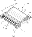
- the ventilation assembly 100 is positioned above the top member of the window frame 2 as seen in the inclination of the roof.
- the ventilation assembly 100 comprises the housing generally designated 7 and having a cover 70 and two end pieces 70a and 70b.
- the housing 7 is divided in the length direction into a left-hand part and a right-hand part, each accommodating a respective inside air inlet 62, 162.
- the inside air inlets coincide in the center to form a flow channel 63.
- a single ventilation unit 61 is provided in the center.
- the ventilation unit 61 comprises a ventilator 611 which is provided with a power supply (not shown).
- the right-hand part and the left hand part is substantially identical or mirror-images of each other. Air from the inside enters through the ventilation flap 5, through the inside air inlets 62, 162 and travels through the flow channel.
- the housing 7 further comprises the through channel 71 having an ambient air intake end 711 and an air exhaust end 712, the through channel 71 further being connected to said inside air inlet 62 via said flow channel 63 so as to provide said fluid connection between the ventilation device 5 of the roof window 1 and the exterior.
- the air is accelerated through the ventilators towards a through channel 71.
- the through channel 71 is arranged substantially across the ventilation assembly 100.
- the through channel has, at each end, an ambient air intake 711 and an exhaust 712, respectively.
- the through channel 71 thus has a fluid connection from one side to the other of ambient air.
- the through channel 71 has a predefined dimension
- the flow channel 63 has a predefined dimension, causing the air pressure from the air entering the air intake end 711 in cooperation with the at least one ventilator 611, 612, 613 of the ventilation unit 61 to result in a flow of air to be directed from the inside air inlet 62 towards the air exhaust end 712 of the through channel 71 so as to provide a suction action.
- the air intake end 711 and the exhaust end 712 can be on either one of the ends of the through channel, and that the numerals 711 and 712 are schematic.
- the air may travel towards any end. The end towards which the air may flow may depend on the rotating direction of the ventilators.
- the housing in the embodiment shown has a top part 702 and a bottom part 701.
- the top part 702 and the bottom part 701 cooperate in creating the respective channels mentioned 62, 63.
- Figs 1 to 4 The embodiment shown in Figs 1 to 4 is of a type that may be arranged and mounted above the window 1, seen in the direction of the inclination of the roof.
- the ventilation assembly 100 is thus positioned on the outside of the building, and arranged above the window 1.
- the ventilation device is arranged on a top side of the frame 4.
- the top side is here meant the side facing the exterior of a building.
- the ventilation assembly is in this embodiment particularly suited for retrofitting onto an already installed roof window 1.
- the length L of the ventilation assembly 100 corresponds in substance to a top casing of the roof window and is arranged in the position of such top casing.
- the roof window system of the embodiment of Figs 5 to 11 may thereby be a slimmer arrangement altogether, and does not require extra space on the roof.
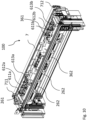
- the ventilation assembly 100 of the embodiment of Figs 5 to 11 comprises a set of two ventilation units 261, 361.
- the ventilation units 261, 361 each comprise a number of ventilators 611a, 612a, 613a and 611b, 612b, 613b, respectively.
- the ventilation assembly 100 may be connected to a moisture sensor, not shown, which may determine at which speed the ventilators rotate.
- each ventilation unit 261, 361 is provided, each including three ventilators 611a, 612a, 613a and 611b, 612b, 613b, respectively.
- a set of inside air inlet channels 262, 362 are provided in the housing 7, which can be seen in Figs 8 to 11 .
- the flow from the ventilation units 61 are both further connected to the through channel 71.
- each ventilation unit 61a, 61b is adapted to be connected to a respective air inlet channel 262, 362 for air intake, and to the ventilation unit 261, 361 to provide a predefined flow path to the through channel 71 to reach ambient air.
- the respective air inlet channels 262, 362 and ventilation units 361, 361 may be isolated from each other and a fluid connection be provided in any suitable manner. However, the through channel 71 may be common for the respective air flows from the respective ventilation unit.
- FIG. 8 Further details of the ventilation assembly 100 are shown in Figs 8 to 11 .
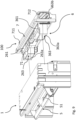
- Fig. 9 it is shown how the ventilation device is arranged to the front of the frame of the window. In this way, the ventilation device may be installed to an already existing window, without the need to cause any damage to the building.
- Power supply to motor 90 is provided by cord 91 which is plugged into the ordinary main supply of the building.
Abstract
Description
- The present invention relates to a roof window system comprising a roof window having at least one frame defining a frame plane and including a pane, the roof window further comprising a ventilation device connected to a frame member and adapted for providing ventilation of a building in which the roof window is mounted, and a ventilation assembly for a roof window having a ventilation device, comprising at least one ventilation unit including a at least one ventilator, the at least one ventilation unit being adapted to be connected to the ventilation device of the roof window. The invention furthermore relates to a method of operating the ventilation assembly in the roof window.
- One of the primary functions in a window, besides admitting light, is to allow stale, warm, or otherwise used or spent air inside the building to exit and allowing fresh air from the exterior to enter the building in which the window is installed. This presupposes that the window is openable. Over time, the provision of ventilation in windows, also in situations in which the window is not open, either because it is a fixed window, or simply is not open, has become more or less standard equipment. This is the result of, among other things, increased focus on improving indoor climatic conditions and the microclimate in buildings. One example of a roof window providing a ventilating aperture is the type of window with a ventilation flap, which in pivot-hung windows also fulfils the double function of operating the window. In such a pivot-hung window, the ventilation flap thus has three positions, viz. a first and closed position, in which the window is closed and no ventilation is provided, a second position, in which the ventilation flap allows passage of air to and from the building, and a third position, in which the window may be operated. Other examples of ventilation assemblies are shown in for instance
DK176947B1 - Natural ventilation provided by such a ventilation device has a number of advantages. Among others, it is free of charge and noise-less. However, in certain fields of applications, mechanical ventilation solutions may be required.
- Examples of prior art roof window systems, including roof windows and ventilation assemblies, are shown in for instance Applicant's European patents
EP0458725B1 andEP0372597B1 , and in published Danish patent applicationDK200001472A - Other examples are shown in documents
DE102004037563A1 ,DE202004020630U1 ,DE19811469A1 andDE9206729U1 . - Although many of the above-mentioned prior art roof window systems, roof windows and ventilation assemblies provide well-functioning solutions, they also require that the roof window is built to receive such a ventilation assembly, typically by designing special parts and/or requiring further investment in the installation of auxiliary parts and installation equipment. Further, in many applications, the ventilation need to be equally powerful for both air intake, and air exhaust. For example in bathrooms, the need for a powerful exhaust is needed in order to keep the harmful dampness out of the room. A way to solve this is to add a bathroom exhaust fan. This is normally done by installing suction which leads the damp inside air to the ambient air of the exterior, either through a wall or a roof of the building. The suction can be done either by providing natural draught, a mechanical fan or a combination. However, installation of such is complicated, since it requires a lot of material fan, piping, roof channel installation and other expensive equipment, not to mention installation by a professional. This makes it costly. It is therefore a need for a solution that provides for increased flexibility and ease of installation and use.
- With this background, it is an object of the present invention to provide an exhaust ventilation assembly for roof window system, which provides a ventilation assembly with an exhaust function and fresh air intake. A window system with a function of the kind provides for a discreet and neat solution that incorporates the air exhaust function. It may also provide for easy installation since the exhaust ventilation assembly may be installed to an already existing roof window.
- It is a further object to provide a roof window system using an exhaust ventilation assembly.
- It is a still further object to provide a method for installation and use of a roof window system, in which operation of the exhaust ventilation assembly is facilitated.
- According to a first aspect of the present invention, these and further objects are achieved with a roof window system of the kind mentioned in the introduction, in which the air exhaust device comprises a housing having predefined dimensions and accommodating said at least one ventilation unit, that each ventilation unit includes a flow channel having a first connecting end connected, in a mounted condition, to an inside air inlet in connection with the interior, and a second connecting end connected, in the mounted condition, to a through channel, and that the housing further comprises the through channel having an ambient air intake end and an air exhaust end, the through channel further being connected to said inside air inlet via said flow channel so as to provide said fluid connection between the ventilation device of the roof window and the exterior.
- Thereby, a roof window system is provided, with which the flexibility and ease of installation aimed at are achieved. This may be done since the roof window system comprises the ventilation assembly, which may be arranged in direct connection with the roof window. The provision of a through flow of air from the air intake end to the air exhaust end, the through flow catches the inside air in the draft and entrains it towards the air exhaust end. The inside air is the air from inside the building. The window system may be installed in any room of a building requiring air exhaust, for instance a bathroom, which may contain hot and humid air. The inside air enters the ventilation assembly through the inside air inlet. There may be at least one ventilation unit, but two or more may be also possible. The ventilation unit, with its ventilator, may allow the air to be drawn towards the through channel. Once the air reaches the through channel, the draft from the ambient air extracts the inside air through the exhaust air end. This solution may be constructed in many sizes, which makes it a flexible solution to be designed according to any requirements. The sizing may depend on the size of the room to be ventilated. Also, depending on the type of roof window and the possibility to add a ventilation device, the ventilation device may be configured in several alternative ways. For instance, in one embodiment, the ventilation device may be assembled on the front part of the frame. The front part may be facing the outside. In this way, the total foot print of he window system may be substantially the same as a roof window. This arrangement also provides for a flexible solution that may be mounted to any roof window, without causing any extra damage to the roof. Another embodiment may be assembled on the top of the frame. This solution provides for moore space to house the ventilator or ventilators. In that way, this solution is suitable for a powerful extraction of larger quantities of air to be extracted.
- In a second aspect, a ventilation assembly is provided as mentioned in claim 10.
- In a third aspect of the invention, a method for operating a ventilation assembly of the roof window system is provided as mentioned in claim 11.
- By using the air flow of the existing ventilation flap in a roof window, a simple installation of the ventilation assembly is done. The ventilation assembly may thus be mounted directly to the roof window, and using the air inlet of the ventilation flap, connecting the ventilation device to that flow path. Since the ventilation device may require a power supply, it may be an advantage to have easy access to a mains power outlet. In that way, air exhaust from a room does not require damaging the roof or a wall in order to connect an external extraction fan.
- Other presently preferred embodiments and further advantages will be apparent from the following detailed description and the dependent claims.
- The invention will be described in more detail below by means of nonlimiting examples of embodiments and with reference to the schematic drawing, in which
-
Fig. 1 is a perspective view of a roof window system according to an embodiment of the invention; -
Fig. 2 is an exploded perspective view of the ventilation assembly of the roof window system according to an embodiment of the invention; -
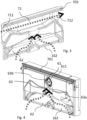
Figs 3 and 4 are perspective views of the top and bottom part respectively of a ventilation assembly according to an embodiment of the invention; -
Figs 5 and 6 are perspective views showing a back and a front respectively, of a ventilation assembly according to an embodiment of the invention; -
Fig. 7 is an exploded view of a roof window and a ventilation flap according to an embodiment of the invention; -
Fig. 8 shows a top break out view of a ventilation assembly according to an embodiment of the invention; -
Fig. 9 is an exploded view of a roof window system according to an embodiment of the invention; -
Fig. 10 is a break out perspective view of a detail of a practical embodiment of a roof window system, corresponding to the one ofFig. 10 ; and -
Fig. 11 is an exploded perspective view of a roof window system a ventilation device and a roof window according to an embodiment of the invention, - The present invention will be described more fully hereinafter with reference to the accompanying drawings, in which preferred embodiments of the invention are shown. This invention may, however, be embodied in many different forms and should not be construed as limited to the embodiments set forth herein; rather, these embodiments are provided so that this disclosure will be thorough and complete, and will fully convey the scope of the invention to those skilled in the art. In the drawings, like numbers refer to like elements.
- Elements having the same or analogous function are denoted by the same reference numerals to which 100, 200 and 300, respectively, has been added.
- Referring first to
Fig 1 showing the overall appearance and principles underlying a roof window system in an embodiment of the invention. The roof window system comprises aroof window 1 and a ventilation assembly generally designated 100. - The
roof window 1 comprises at least one frame, in the embodiment shown and described two frames, of which oneframe 2 is a stationary frame and asash 3 encasing apane 4. Thesash 3 is typically openable and connected to theframe 2 via a hinge connection (not indicated), but may also be fixed, i.e. not as such openable, but allowing passage of air as will be described in further detail below. Theframe 2 is, in a manner known per se, substantially rectangular and has a top member, and further a bottom member and two side members, not shown in detail. Thesash 3 also has a top member, two side members, and a bottom member, not shown in detail. Theframe 2 is adapted to be built into a roof structure of virtually any kind, typically comprising a number of rafters and battens, and further non-shown details such as vapour barrier collars etc., below a roofing material. - As used in this description, in the case of an openable window, a closed position of the
roof window 1 means a position in which the frame plane and the sash plane coincide, that is form an angle of 0 degrees with each other. Similarly an open position of theroof window 1 as used herein generally means a position in which thesash 3 is tilted about the pivot hinge axis such that the frame plane and the sash plane no longer coincide. The window according to the invention may be centre-hung in that thesash 3 is connected to theframe 2 by a pivot hinge (not shown) provided between side members of theframe 2 andsash 3, respectively, to be openable by tilting thesash 3 of thewindow 1 about a pivot hinge axis defined by the pivot hinge. The window according to the invention may be top-hung, with or without an intermediate frame structure, have the hinge axis somewhere between the top and the centre, be side-hung or for that matter even be bottom-hung, or fixed, i.e. not openable. As will be described in further detail below, the roof window system provides for ventilation in the closed position of the window. - The
sash 3 andframe 2 of the window according to the invention may be made of wooden members or members made of cast or extruded polyurethane (PUR). In the installed position, theframe 2 andsash 3 are protected, in a manner known per se, by cover elements including a cladding and a flashing arrangement. Towards the interior, a suitable finishing may be provided, for instance comprising a lining panel. - The
roof window 1 has aventilation device 5, which in the embodiment shown comprises aventilation flap 51, which is connected to the top member of thesash 3 via a hinge connection, not shown. Theventilation flap 51 is an elongate element, which is connected to the top sash member by means of the hinge connection and furthermore to a lock, not shown in detail, by means of a link connection, not shown, adapted to enable theventilation flap 51 to be placed in at least two, and preferably at least three, different positions including a closed and at least one open position. In a top member of thesash 3, a top sash module is provided, for instance of the kind described in Applicant's international application with publication No.WO 2013/050039 A1 , allowing the passage of air when the ventilation flap is in the open position. - Operating a handle of the
ventilation device 5 rotates theventilation flap 51 from an open position to a closed position and vice versa. One or more intermediate positions, in which theventilation flap 51 may be temporarily locked, may be defined between the open and closed position. In the embodiment shown and described, theventilation flap 51 is adapted to assume two positions, viz. a first or closed position, in which theroof window 1 is closed and no ventilation is provided, and a second and ventilating position, in which theroof window 1 is still closed but a ventilation aperture is provided to allow air passage. There may be a third alternative and entirely open position, in which thesash 3 is able to pivot relative to theframe 2 to open the window. - The
roof window 1 of the invention forms part of a roof window system, which in addition to theroof window 1 comprises a ventilation assembly generally designated 100. - The
ventilation assembly 100 comprisies anair exhaust device 6 for extracting inside air to the exterior, comprising at least oneventilation unit 61 including at least oneventilator 611, 612, 613. The ventilation unit orunits 61 is/are adapted to be connected to theventilation device 5 of theroof window 1 so as to provide fluid connection between the interior of the building and the exterior, in the mounted condition. - The
air exhaust device 6 comprises ahousing 7 having predefined dimensions and accommodating said at least oneventilation unit 61. As will be described in further detail below, eachventilation unit 61 includes aflow channel 63 having a first connectingend 63a connected, in a mounted condition, to aninside air inlet 62 in connection with the interior, and a secondconnecting end 63b connected, in the mounted condition, to a through channel (71). - Details of one embodiment of the
ventilation assembly 100 will now be described in further detail with reference to the remaining drawing figures. - In the embodiment shown, the
ventilation assembly 100 is positioned above the top member of thewindow frame 2 as seen in the inclination of the roof. - In
Figs 2 and3 , it is shown that theventilation assembly 100 comprises the housing generally designated 7 and having acover 70 and twoend pieces housing 7 is divided in the length direction into a left-hand part and a right-hand part, each accommodating a respectiveinside air inlet flow channel 63. In the center, asingle ventilation unit 61 is provided. Theventilation unit 61 comprises aventilator 611 which is provided with a power supply (not shown). - The right-hand part and the left hand part is substantially identical or mirror-images of each other. Air from the inside enters through the
ventilation flap 5, through theinside air inlets - The
housing 7 further comprises the throughchannel 71 having an ambientair intake end 711 and anair exhaust end 712, the throughchannel 71 further being connected to said insideair inlet 62 via saidflow channel 63 so as to provide said fluid connection between theventilation device 5 of theroof window 1 and the exterior. - The air is accelerated through the ventilators towards a through
channel 71. The throughchannel 71 is arranged substantially across theventilation assembly 100. The through channel has, at each end, anambient air intake 711 and anexhaust 712, respectively. The throughchannel 71 thus has a fluid connection from one side to the other of ambient air. - The through
channel 71 has a predefined dimension, and theflow channel 63 has a predefined dimension, causing the air pressure from the air entering theair intake end 711 in cooperation with the at least oneventilator 611, 612, 613 of theventilation unit 61 to result in a flow of air to be directed from theinside air inlet 62 towards theair exhaust end 712 of the throughchannel 71 so as to provide a suction action. - Once the inside air has travelled through the ventilators, the air enters the through
channel 71. The inside air is then caught in the draft in the throughchannel 71 and passed through theexhaust end 712. It should be noted that theair intake end 711 and theexhaust end 712 can be on either one of the ends of the through channel, and that thenumerals - As seen in
Figs 2 to 4 , the housing in the embodiment shown has atop part 702 and abottom part 701. Thetop part 702 and thebottom part 701 cooperate in creating the respective channels mentioned 62, 63. - The embodiment shown in
Figs 1 to 4 is of a type that may be arranged and mounted above thewindow 1, seen in the direction of the inclination of the roof. Theventilation assembly 100 is thus positioned on the outside of the building, and arranged above thewindow 1. - Referring now to
Figs 5 to 11 , in which a preferred embodiment of the invention is shown. The ventilation device is arranged on a top side of theframe 4. The top side is here meant the side facing the exterior of a building. - The ventilation assembly is in this embodiment particularly suited for retrofitting onto an already installed
roof window 1. In this regard, it is particularly advantategous that the length L of theventilation assembly 100 corresponds in substance to a top casing of the roof window and is arranged in the position of such top casing. - The roof window system of the embodiment of
Figs 5 to 11 may thereby be a slimmer arrangement altogether, and does not require extra space on the roof. - As seen in
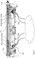
Fig. 8 , theventilation assembly 100 of the embodiment ofFigs 5 to 11 comprises a set of twoventilation units ventilation units ventilators ventilators 611, 612, 613 to extract the inside air towards the throughchannel 71 of theventilation assembly 100. In any of the embodiments, theventilation assembly 100 may be connected to a moisture sensor, not shown, which may determine at which speed the ventilators rotate. Once the roof window system including theroof window 1 and theventilation assembly 100 is mounted, theventilation assembly 100 may be operated to perform the desired ventilation. - In the
housing 7 of theventilation assembly 100 of the present embodiment, twoventilation units ventilators air inlet channels housing 7, which can be seen inFigs 8 to 11 . The flow from theventilation units 61 are both further connected to the throughchannel 71. Thus, each ventilation unit 61a, 61b is adapted to be connected to a respectiveair inlet channel ventilation unit channel 71 to reach ambient air. - The respective
air inlet channels ventilation units channel 71 may be common for the respective air flows from the respective ventilation unit. - Further details of the
ventilation assembly 100 are shown inFigs 8 to 11 . - In
Fig. 9 , it is shown how the ventilation device is arranged to the front of the frame of the window. In this way, the ventilation device may be installed to an already existing window, without the need to cause any damage to the building. Power supply tomotor 90 is provided bycord 91 which is plugged into the ordinary main supply of the building. - It should be noted that the above description of preferred embodiments serves only as an example, and that a person skilled in the art will know that numerous variations are possible without deviating from the scope of the claims.
- Itemised list of embodiments:
-
Embodiment 1. A roof window system comprising:- a roof window (1) having at least one frame (2, 3) defining a frame plane and including a pane (4), the roof window (1) further comprising a ventilation device (5) connected to a frame member and adapted for providing ventilation of the interior of a building in which the roof window is mounted, and
- a ventilation assembly (100) comprising an air exhaust device (6) for extracting inside air to the exterior, comprising at least one ventilation unit (61; 261, 361) including at least one ventilator (611, 612, 613), the at least one ventilation unit (61; 261, 361) being adapted to be connected to the ventilation device (5) of the roof window (1) so as to provide fluid connection between the interior of the building and the exterior, in the mounted condition,
- characterized in that
- the air exhaust device (6) comprises a housing (7) having predefined dimensions and accommodating said at least one ventilation unit (61),
- that each ventilation unit (61; 261, 361) includes a flow channel (63) having a first connecting end (63a; 263a, 363a) connected, in a mounted condition, to an inside air inlet (62, 162; 262, 362) in connection with the interior, and a second connecting end (63b; 263b, 363b) connected, in the mounted condition, to a through channel (71), and
- that the housing (7) further comprises the through channel (71) having an ambient air intake end (711) and an air exhaust end (712), the through channel (71) further being connected to said inside air inlet (62, 162; 262, 362) via said flow channel (63; 263, 363) so as to provide said fluid connection between the ventilation device (5) of the roof window (1) and the exterior.
-
Embodiment 2. A roof window system according toembodiment 1, wherein the through channel (71) has a predefined dimension, and the flow channel (63) has a predefined dimension, causing the air pressure from the air entering the air intake end (711) in cooperation with the at least one ventilator (611, 612, 613) of the ventilation unit (61) to result in a flow of air to be directed from the inside air inlet (62) towards the air exhaust end (712) of the through channel (71) so as to provide a suction action. -
Embodiment 3. A roof window system according toembodiment -
Embodiment 4. A roof window system according toembodiment 3, wherein the length (L) of the ventilation assembly (100) corresponds in substance to a top casing of the roof window and is arranged in the position of such top casing. -
Embodiment 5. A roof window system according to any of the preceding embodiments, wherein the ventilation device (5) of the roof window (1) comprises a ventilation flap (51) openable between an open and a closed position from the inside of the building, wherein said inside air inlet (62) is arranged so that when the ventilation flap (61) is in an open position, a fluid connection between the interior and the inside air inlet (62) is provided. -
Embodiment 6. A roof window system according toembodiment -
Embodiment 7. A roof window system according to any of the preceding embodiments, wherein the ventilator (611, 612, 613) is connected to a power supply (90, 91) for receiving operating power. - Embodiment 8. A roof window system according to
embodiment 7, wherein the power supply has a switch to allow the ventilator (611, 612, 613) to switch between an operation mode and an off mode. - Embodiment 9. A roof window system according to
embodiments 5 and 8, wherein the switch is operated by operating the ventilation flap (51) so that when the ventilation flap (51) is open, the switch is set in an operation mode allowing the ventilators to operate, and when the ventilation flap is closed, the swicth is in an off mode whereby the ventilators are in an off mode. - Embodiment 10. A ventilation assembly comprising an air exhaust device (6) for extracting inside air to the exterior, comprising at least one ventilation unit (61) including at least one ventilator (611, 612, 613), the at least one ventilation unit (61) being adapted to be connected to a ventilation device (5) of a roof window,
characterized in that- the air exhaust device (6) comprises a housing (7) accommodating said ventilation units (61), and
- each ventilation unit (61) includes a flow channel (63) having a first connecting end connected, in a mounted condition, to an inside air inlet (62) in connection with the interior, and a second connecting end connected, in the mounted condition, to a through channel (71), and
- the housing further comprises the through channel (71) having an ambient air intake end (711) and an air exhaust end (712), the through channel (71) further being connected to said air inlet channel (62) so as to provide a fluid connection between the ventilation device of the roof window and ambient air of the exterior, the ventilation device further being configured to be arranged in connection to a roof window.
- Embodiment 11. A method of operating a ventilation assembly of the roof window system of any one of
embodiments 1 to 9, the method comprising the steps of:- providing the ventilation device (5) of the roof window (1) as comprising a ventilation flap (51),
- activating the ventilation flap (51) of the roof window (1) whereby a fluid connection between the interior and the exterior is provided,
- wherein the ventilation flap, in the open position, operates a switch to assume an operation mode in which the ventilators start running for extracting inside air to the exterior.
- Embodiment 12. Method according to embodiment 11, further comprising:
closing the ventilation flap (5), whereby the fluid connection is interrupted and the switch is set in an off mode. - Embodiment 13. Method according to embodiment 11 or 12, further comprising:
operating the ventilation flap (5) to a sash opening position, in which the ventilation flap deactivates a lock so that the roof window is allowed to be opened. -
- 1
- roof window
- 2
- frame
- 3
- sash
- 4
- pane
- 5
- ventilation device
51 ventilation flap - 100
- ventilation assembly
- 6
- air exhaust device
61 ventilation unit
261 ventilation unit
361 ventilation unit
611 ventilator
611a ventilator
611b ventilator
612 ventilator
611a ventilator
612b ventilator
613 ventilator
613a ventilator
613b ventilator
62 inside air inlet
162 inside air inlet
262 inside air inlet
362 inside air inlet
63 flow channel
63a first connecting end
63b second connecting end
263 flow channel
263a first connecting end
363 flow channel
363a first connecting end
363b second connecting end - 7
- housing
70 cover
70a first end piece
70b second end piece
71 through channel
701 bottom part
702 top part
711 air intake end
712 exhaust end - 90
- motor
- 91
- cord
- H
- height
- L
- length
- W
- width
Claims (12)
- A roof window system comprising:a roof window (1) having at least one frame (2, 3) defining a frame plane and including a pane (4), the roof window (1) further comprising a ventilation device (5) connected to a frame member and adapted for providing ventilation of the interior of a building in which the roof window is mounted, anda ventilation assembly (100) comprising an air exhaust device (6) for extracting inside air to the exterior, comprising at least one ventilation unit (261, 361) including at least one ventilator (611a, 612a, 613a, 611b, 612b, 613c), the at least one ventilation unit (261, 361) being adapted to be connected to the ventilation device (5) of the roof window (1) so as to provide fluid connection between the interior of the building and the exterior, in the mounted condition,characterized in thatthe air exhaust device (6) comprises a housing (7) having predefined dimensions including a predefined width (W), a predefined length (L) and a predefined height (H), and accommodating said at least one ventilation unit (61),that each ventilation unit (261, 361) includes a flow channel (263, 363) having a first connecting end (263a, 363a) connected, in a mounted condition, to an inside air inlet (262, 362) in connection with the interior, and a second connecting end (263b, 363b) connected, in the mounted condition, to a through channel (71),that the housing (7) further comprises the through channel (71) having an ambient air intake end (711) and an air exhaust end (712), the through channel (71) further being connected to said inside air inlet (262, 362) via said flow channel (263, 363) so as to provide said fluid connection between the ventilation device (5) of the roof window (1) and the exterior, andthat the length (L) of the ventilation assembly (100) corresponds in substance to a top casing of the roof window and is arranged in the position of such top casing.
- A roof window system according to claim 1, wherein the through channel (71) has a predefined dimension, and the flow channel (263, 363) has a predefined dimension, causing the air pressure from the air entering the air intake end (711) in cooperation with the at least one ventilator (611a, 612a, 613a, 611b, 612b, 613b) of the ventilation unit (261, 361) to result in a flow of air to be directed from the inside air inlet (262, 362) towards the air exhaust end (712) of the through channel (71) so as to provide a suction action.
- A roof window system according to claim 1 or 2, wherein wherein the housing (7) is divided in the height direction into a bottom part (701) and a top part (702), and wherein said inside air inlet (262, 362) is formed by inside air inlet channel parts in the respective bottom and top parts (701, 702).
- A roof window system according to any of the preceding claims, wherein the ventilation device (5) of the roof window (1) comprises a ventilation flap (51) openable between an open and a closed position from the inside of the building, wherein said inside air inlet (262, 362) is arranged so that when the ventilation flap (61) is in an open position, a fluid connection between the interior and the inside air inlet (262, 362) is provided.
- A roof window system according to claim 1 or 2, wherein the through channel (71) of the ventilation assembly (100) is accommodated directly within the housing (7).
- A roof window system according to any of the preceding claims, wherein the ventilator (611a, 612a, 613a, 611b, 612b, 613b) is connected to a power supply (90, 91) for receiving operating power.
- A roof window system according to claim 6, wherein the power supply has a switch to allow the ventilator (611a, 612a, 613a, 611b, 612b, 613b) to switch between an operation mode and an off mode.
- A roof window system according to claims 4 and 7, wherein the switch is operated by operating the ventilation flap (51) so that when the ventilation flap (51) is open, the switch is set in an operation mode allowing the ventilators to operate, and when the ventilation flap is closed, the swicth is in an off mode whereby the ventilators are in an off mode.
- A ventilation assembly comprising an air exhaust device (6) for extracting inside air to the exterior, comprising at least one ventilation unit (261, 361) including at least one ventilator (611a, 612a, 613a, 611b, 612b, 613b), the at least one ventilation unit (261, 361) being adapted to be connected to a ventilation device (5) of a roof window,
characterized in thatthe air exhaust device (6) comprises a housing (7) accommodating said ventilation units (261, 361), andeach ventilation unit (261, 361) includes a flow channel (263, 363) having a first connecting end connected, in a mounted condition, to an inside air inlet (262, 362) in connection with the interior, and a second connecting end connected, in the mounted condition, to a through channel (71), andthe housing further comprises the through channel (71) having an ambient air intake end (711) and an air exhaust end (712), the through channel (71) further being connected to said air inlet channel (262, 362) so as to provide a fluid connection between the ventilation device of the roof window and ambient air of the exterior, the ventilation device further being configured to be arranged in connection to a roof window, for retrofitting on an already installed roof window, in the position of a top casing of the roof window, a length (L) of the ventilation assembly (100) corresponding in substance to such top casing of the roof window. - A method of operating a ventilation assembly of the roof window system of any one of claims 1 to 8, the method comprising the steps of:providing the ventilation device (5) of the roof window (1) as comprising a ventilation flap (51),activating the ventilation flap (51) of the roof window (1) whereby a fluid connection between the interior and the exterior is provided,wherein the ventilation flap, in the open position, operates a switch to assume an operation mode in which the ventilators start running for extracting inside air to the exterior.
- Method according to claim 10, further comprising:
closing the ventilation flap (5), whereby the fluid connection is interrupted and the switch is set in an off mode. - Method according to claim 10 or 11, further comprising:
operating the ventilation flap (5) to a sash opening position, in which the ventilation flap deactivates a lock so that the roof window is allowed to be opened.
Applications Claiming Priority (2)
| Application Number | Priority Date | Filing Date | Title |
|---|---|---|---|
| DKPA201670807A DK180278B1 (en) | 2016-10-14 | 2016-10-14 | A roof window system comprising a ventilation assembly with an exhaust device |
| EP17196345.7A EP3309468B1 (en) | 2016-10-14 | 2017-10-13 | A roof window system comprising a ventilation assembly with an exhaust device and method of operating a ventilation assembly of such a roof window system |
Related Parent Applications (2)
| Application Number | Title | Priority Date | Filing Date |
|---|---|---|---|
| EP17196345.7A Division-Into EP3309468B1 (en) | 2016-10-14 | 2017-10-13 | A roof window system comprising a ventilation assembly with an exhaust device and method of operating a ventilation assembly of such a roof window system |
| EP17196345.7A Division EP3309468B1 (en) | 2016-10-14 | 2017-10-13 | A roof window system comprising a ventilation assembly with an exhaust device and method of operating a ventilation assembly of such a roof window system |
Publications (2)
| Publication Number | Publication Date |
|---|---|
| EP4235045A2 true EP4235045A2 (en) | 2023-08-30 |
| EP4235045A3 EP4235045A3 (en) | 2024-01-03 |
Family
ID=60143518
Family Applications (2)
| Application Number | Title | Priority Date | Filing Date |
|---|---|---|---|
| EP23179221.9A Pending EP4235045A3 (en) | 2016-10-14 | 2017-10-13 | A roof window system comprising a ventilation assembly with an exhaust device and method of operating a ventilation assembly of such a roof window system |
| EP17196345.7A Active EP3309468B1 (en) | 2016-10-14 | 2017-10-13 | A roof window system comprising a ventilation assembly with an exhaust device and method of operating a ventilation assembly of such a roof window system |
Family Applications After (1)
| Application Number | Title | Priority Date | Filing Date |
|---|---|---|---|
| EP17196345.7A Active EP3309468B1 (en) | 2016-10-14 | 2017-10-13 | A roof window system comprising a ventilation assembly with an exhaust device and method of operating a ventilation assembly of such a roof window system |
Country Status (4)
| Country | Link |
|---|---|
| EP (2) | EP4235045A3 (en) |
| DK (1) | DK180278B1 (en) |
| ES (1) | ES2956669T3 (en) |
| PL (1) | PL3309468T3 (en) |
Families Citing this family (3)
| Publication number | Priority date | Publication date | Assignee | Title |
|---|---|---|---|---|
| DK180879B1 (en) | 2019-12-30 | 2022-06-13 | Vkr Holding As | A roof window system with a ventilation unit mounted adjacent to the roof window, and a method of providing ventilation for a building |
| DK180977B1 (en) * | 2019-12-30 | 2022-08-29 | Vkr Holding As | A roof window system with a ventilation unit mounted adjacent to the roof window, a roof structure including a roof window system, a method of providing a roof window system and a method of retrofitting a roof window system |
| GB202207820D0 (en) * | 2022-05-27 | 2022-07-13 | Keylite Roof Windows Ltd | A hood for a rood window |
Citations (9)
| Publication number | Priority date | Publication date | Assignee | Title |
|---|---|---|---|---|
| EP0372597B1 (en) | 1988-11-11 | 1992-07-22 | V. Kann Rasmussen Industri A/S | Ventilating roof window |
| DE9206729U1 (en) | 1992-02-03 | 1993-06-03 | Berner, Erling, Zug, Ch | |
| EP0458725B1 (en) | 1990-05-23 | 1994-06-29 | V. Kann Rasmussen Industri A/S | Window with mechanical ventilation |
| DE19811469A1 (en) | 1998-03-17 | 1999-09-30 | Rehfus Bernd | Force ventilation of rooms and cabins |
| DK200001472A (en) | 2000-10-04 | 2002-04-05 | Vkr Holding As | Window with ventilation openings |
| DE202004020630U1 (en) | 2004-08-03 | 2006-01-26 | Boden, Christian | Roof light-integrated solar ventilation system, has ventilators that are integrated into building fabric, and step warm-up controller provided for shiftable connection of ventilators based on tensions |
| DE102004037563A1 (en) | 2004-08-03 | 2006-03-16 | Christian Boden | Roof light-integrated solar ventilation system, has ventilators that are integrated into building fabric, and step warm-up controller provided for shiftable connection of ventilators based on tensions |
| DK176947B1 (en) | 2007-12-03 | 2010-06-21 | Form & Plast As | Vent |
| WO2013050039A1 (en) | 2011-10-04 | 2013-04-11 | Vkr Holding A/S | A roof window with a top sash module |
Family Cites Families (8)
| Publication number | Priority date | Publication date | Assignee | Title |
|---|---|---|---|---|
| US657949A (en) * | 1899-09-15 | 1900-09-18 | Claes Oscar Meurk | Window-ventilator. |
| US792990A (en) * | 1904-04-05 | 1905-06-20 | James Hough | Ventilator. |
| GB162405A (en) * | 1920-02-02 | 1921-05-02 | Henry Ismay Moralee Ross | Improved exhaust ventilators |
| GB2474529B (en) * | 2010-03-10 | 2011-09-21 | Green Structures Ltd | Ventilation system |
| KR101433437B1 (en) * | 2012-03-19 | 2014-08-27 | (주)엘지하우시스 | Ventilation equipment for window |
| KR20130106008A (en) * | 2012-03-19 | 2013-09-27 | (주)엘지하우시스 | Window system having heat exchanging module with low noise |
| DK179084B1 (en) * | 2013-03-12 | 2017-10-16 | Vkr Holding As | A roof window system comprising a ventilation assembly and method of operating such a ventilation assembly |
| DE202016100906U1 (en) * | 2016-02-19 | 2016-07-05 | Vkr Holding A/S | Roof window system with a skylight and a ventilation structure |
-
2016
- 2016-10-14 DK DKPA201670807A patent/DK180278B1/en active IP Right Grant
-
2017
- 2017-10-13 PL PL17196345.7T patent/PL3309468T3/en unknown
- 2017-10-13 EP EP23179221.9A patent/EP4235045A3/en active Pending
- 2017-10-13 ES ES17196345T patent/ES2956669T3/en active Active
- 2017-10-13 EP EP17196345.7A patent/EP3309468B1/en active Active
Patent Citations (9)
| Publication number | Priority date | Publication date | Assignee | Title |
|---|---|---|---|---|
| EP0372597B1 (en) | 1988-11-11 | 1992-07-22 | V. Kann Rasmussen Industri A/S | Ventilating roof window |
| EP0458725B1 (en) | 1990-05-23 | 1994-06-29 | V. Kann Rasmussen Industri A/S | Window with mechanical ventilation |
| DE9206729U1 (en) | 1992-02-03 | 1993-06-03 | Berner, Erling, Zug, Ch | |
| DE19811469A1 (en) | 1998-03-17 | 1999-09-30 | Rehfus Bernd | Force ventilation of rooms and cabins |
| DK200001472A (en) | 2000-10-04 | 2002-04-05 | Vkr Holding As | Window with ventilation openings |
| DE202004020630U1 (en) | 2004-08-03 | 2006-01-26 | Boden, Christian | Roof light-integrated solar ventilation system, has ventilators that are integrated into building fabric, and step warm-up controller provided for shiftable connection of ventilators based on tensions |
| DE102004037563A1 (en) | 2004-08-03 | 2006-03-16 | Christian Boden | Roof light-integrated solar ventilation system, has ventilators that are integrated into building fabric, and step warm-up controller provided for shiftable connection of ventilators based on tensions |
| DK176947B1 (en) | 2007-12-03 | 2010-06-21 | Form & Plast As | Vent |
| WO2013050039A1 (en) | 2011-10-04 | 2013-04-11 | Vkr Holding A/S | A roof window with a top sash module |
Also Published As
| Publication number | Publication date |
|---|---|
| EP3309468A3 (en) | 2018-08-29 |
| PL3309468T3 (en) | 2024-01-03 |
| EP3309468B1 (en) | 2023-07-19 |
| DK180278B1 (en) | 2020-09-25 |
| EP4235045A3 (en) | 2024-01-03 |
| ES2956669T3 (en) | 2023-12-26 |
| EP3309468A2 (en) | 2018-04-18 |
| DK201670807A1 (en) | 2018-05-07 |
Similar Documents
| Publication | Publication Date | Title |
|---|---|---|
| EP3309468B1 (en) | A roof window system comprising a ventilation assembly with an exhaust device and method of operating a ventilation assembly of such a roof window system | |
| EP3655609B1 (en) | Roof window system with improved transition means between a roof window and a ventilation assembly | |
| EP2784240B1 (en) | A roof window system comprising a roof window and a ventilation assembly, and method of operating the ventilation assembly in the roof window | |
| US11686096B2 (en) | Roof window system with a ventilation unit mounted adjacent to the roof window, a roof structure including a roof window system, a method of providing a roof window system and a method of retrofitting a roof window system | |
| KR20170046117A (en) | Ventilation Apparatus of Hinge Door | |
| KR20160142605A (en) | a ventilation equipment built in window | |
| KR101884398B1 (en) | Heat recovery ventilator | |
| US20030097805A1 (en) | Retractable in house open stairwell cover | |
| EP3348736B1 (en) | Roof window system with a ventilation assembly with improved flow path and method of operating the ventilation assembly | |
| JP4097159B2 (en) | Door ventilation equipment | |
| KR102087826B1 (en) | Ventilator for window installation | |
| KR100893073B1 (en) | Bathroom ventilating system combined with funcion of ventilating a balcony | |
| KR20060098281A (en) | Ventilation system | |
| KR200424327Y1 (en) | Ventilator | |
| KR100916848B1 (en) | Natural ventilating device | |
| JP5351716B2 (en) | Building ventilation system | |
| KR100261696B1 (en) | Out door unit for air conditioner | |
| KR900009905Y1 (en) | Ventilating sky-light | |
| JP3978676B2 (en) | Window ventilator | |
| KR20230039323A (en) | External wind inflow guide equipment | |
| JP2016065647A (en) | Ventilating fan device and building comprising the same | |
| KR20220107342A (en) | Multi-purpose louver device for outdoor unit | |
| JP2005273177A (en) | Window ventilator and bathroom having the ventilator | |
| JPH05118599A (en) | Structure of air supplying port for indoor ventilation | |
| JPH0584790U (en) | Bay window ventilation system |
Legal Events
| Date | Code | Title | Description |
|---|---|---|---|
| PUAI | Public reference made under article 153(3) epc to a published international application that has entered the european phase |
Free format text: ORIGINAL CODE: 0009012 |
|
| STAA | Information on the status of an ep patent application or granted ep patent |
Free format text: STATUS: THE APPLICATION HAS BEEN PUBLISHED |
|
| AC | Divisional application: reference to earlier application |
Ref document number: 3309468 Country of ref document: EP Kind code of ref document: P |
|
| AK | Designated contracting states |
Kind code of ref document: A2 Designated state(s): AL AT BE BG CH CY CZ DE DK EE ES FI FR GB GR HR HU IE IS IT LI LT LU LV MC MK MT NL NO PL PT RO RS SE SI SK SM TR |
|
| PUAL | Search report despatched |
Free format text: ORIGINAL CODE: 0009013 |
|
| RAC | Divisional application: reference to earlier application (corrected) |
Ref document number: 3309468 Country of ref document: EP Kind code of ref document: P |
|
| AK | Designated contracting states |
Kind code of ref document: A3 Designated state(s): AL AT BE BG CH CY CZ DE DK EE ES FI FR GB GR HR HU IE IS IT LI LT LU LV MC MK MT NL NO PL PT RO RS SE SI SK SM TR |
|
| RIC1 | Information provided on ipc code assigned before grant |
Ipc: F24F 13/18 20060101ALI20231128BHEP Ipc: E06B 7/10 20060101ALI20231128BHEP Ipc: E04D 13/03 20060101ALI20231128BHEP Ipc: F24F 7/08 20060101AFI20231128BHEP |
|
| STAA | Information on the status of an ep patent application or granted ep patent |
Free format text: STATUS: REQUEST FOR EXAMINATION WAS MADE |