EP4235012A1 - Tank comprising inner and outer enclosures and at least one system for connecting flexible radial strips connecting said enclosures - Google Patents
Tank comprising inner and outer enclosures and at least one system for connecting flexible radial strips connecting said enclosures Download PDFInfo
- Publication number
- EP4235012A1 EP4235012A1 EP23156204.2A EP23156204A EP4235012A1 EP 4235012 A1 EP4235012 A1 EP 4235012A1 EP 23156204 A EP23156204 A EP 23156204A EP 4235012 A1 EP4235012 A1 EP 4235012A1
- Authority
- EP
- European Patent Office
- Prior art keywords
- enclosure
- well
- internal
- blades
- central part
- Prior art date
- Legal status (The legal status is an assumption and is not a legal conclusion. Google has not performed a legal analysis and makes no representation as to the accuracy of the status listed.)
- Pending
Links
- 238000006073 displacement reaction Methods 0.000 claims abstract description 4
- UFHFLCQGNIYNRP-UHFFFAOYSA-N Hydrogen Chemical compound [H][H] UFHFLCQGNIYNRP-UHFFFAOYSA-N 0.000 claims description 14
- 229910052739 hydrogen Inorganic materials 0.000 claims description 14
- 239000001257 hydrogen Substances 0.000 claims description 14
- 230000006835 compression Effects 0.000 claims description 4
- 238000007906 compression Methods 0.000 claims description 4
- 238000010521 absorption reaction Methods 0.000 abstract description 2
- 238000009413 insulation Methods 0.000 description 3
- 239000002131 composite material Substances 0.000 description 2
- 230000008602 contraction Effects 0.000 description 2
- 238000003780 insertion Methods 0.000 description 2
- 230000037431 insertion Effects 0.000 description 2
- 238000009434 installation Methods 0.000 description 2
- 230000000712 assembly Effects 0.000 description 1
- 238000000429 assembly Methods 0.000 description 1
- 230000000903 blocking effect Effects 0.000 description 1
- 230000007423 decrease Effects 0.000 description 1
- 230000000694 effects Effects 0.000 description 1
- 239000000463 material Substances 0.000 description 1
- 238000000034 method Methods 0.000 description 1
- 238000003466 welding Methods 0.000 description 1
Images


Classifications
-
- F—MECHANICAL ENGINEERING; LIGHTING; HEATING; WEAPONS; BLASTING
- F17—STORING OR DISTRIBUTING GASES OR LIQUIDS
- F17C—VESSELS FOR CONTAINING OR STORING COMPRESSED, LIQUEFIED OR SOLIDIFIED GASES; FIXED-CAPACITY GAS-HOLDERS; FILLING VESSELS WITH, OR DISCHARGING FROM VESSELS, COMPRESSED, LIQUEFIED, OR SOLIDIFIED GASES
- F17C3/00—Vessels not under pressure
- F17C3/02—Vessels not under pressure with provision for thermal insulation
- F17C3/04—Vessels not under pressure with provision for thermal insulation by insulating layers
-
- F—MECHANICAL ENGINEERING; LIGHTING; HEATING; WEAPONS; BLASTING
- F17—STORING OR DISTRIBUTING GASES OR LIQUIDS
- F17C—VESSELS FOR CONTAINING OR STORING COMPRESSED, LIQUEFIED OR SOLIDIFIED GASES; FIXED-CAPACITY GAS-HOLDERS; FILLING VESSELS WITH, OR DISCHARGING FROM VESSELS, COMPRESSED, LIQUEFIED, OR SOLIDIFIED GASES
- F17C1/00—Pressure vessels, e.g. gas cylinder, gas tank, replaceable cartridge
- F17C1/12—Pressure vessels, e.g. gas cylinder, gas tank, replaceable cartridge with provision for thermal insulation
-
- F—MECHANICAL ENGINEERING; LIGHTING; HEATING; WEAPONS; BLASTING
- F17—STORING OR DISTRIBUTING GASES OR LIQUIDS
- F17C—VESSELS FOR CONTAINING OR STORING COMPRESSED, LIQUEFIED OR SOLIDIFIED GASES; FIXED-CAPACITY GAS-HOLDERS; FILLING VESSELS WITH, OR DISCHARGING FROM VESSELS, COMPRESSED, LIQUEFIED, OR SOLIDIFIED GASES
- F17C2201/00—Vessel construction, in particular geometry, arrangement or size
- F17C2201/01—Shape
- F17C2201/0104—Shape cylindrical
- F17C2201/0109—Shape cylindrical with exteriorly curved end-piece
-
- F—MECHANICAL ENGINEERING; LIGHTING; HEATING; WEAPONS; BLASTING
- F17—STORING OR DISTRIBUTING GASES OR LIQUIDS
- F17C—VESSELS FOR CONTAINING OR STORING COMPRESSED, LIQUEFIED OR SOLIDIFIED GASES; FIXED-CAPACITY GAS-HOLDERS; FILLING VESSELS WITH, OR DISCHARGING FROM VESSELS, COMPRESSED, LIQUEFIED, OR SOLIDIFIED GASES
- F17C2201/00—Vessel construction, in particular geometry, arrangement or size
- F17C2201/05—Size
- F17C2201/054—Size medium (>1 m3)
-
- F—MECHANICAL ENGINEERING; LIGHTING; HEATING; WEAPONS; BLASTING
- F17—STORING OR DISTRIBUTING GASES OR LIQUIDS
- F17C—VESSELS FOR CONTAINING OR STORING COMPRESSED, LIQUEFIED OR SOLIDIFIED GASES; FIXED-CAPACITY GAS-HOLDERS; FILLING VESSELS WITH, OR DISCHARGING FROM VESSELS, COMPRESSED, LIQUEFIED, OR SOLIDIFIED GASES
- F17C2203/00—Vessel construction, in particular walls or details thereof
- F17C2203/01—Reinforcing or suspension means
- F17C2203/014—Suspension means
- F17C2203/015—Bars
-
- F—MECHANICAL ENGINEERING; LIGHTING; HEATING; WEAPONS; BLASTING
- F17—STORING OR DISTRIBUTING GASES OR LIQUIDS
- F17C—VESSELS FOR CONTAINING OR STORING COMPRESSED, LIQUEFIED OR SOLIDIFIED GASES; FIXED-CAPACITY GAS-HOLDERS; FILLING VESSELS WITH, OR DISCHARGING FROM VESSELS, COMPRESSED, LIQUEFIED, OR SOLIDIFIED GASES
- F17C2203/00—Vessel construction, in particular walls or details thereof
- F17C2203/03—Thermal insulations
- F17C2203/0391—Thermal insulations by vacuum
-
- F—MECHANICAL ENGINEERING; LIGHTING; HEATING; WEAPONS; BLASTING
- F17—STORING OR DISTRIBUTING GASES OR LIQUIDS
- F17C—VESSELS FOR CONTAINING OR STORING COMPRESSED, LIQUEFIED OR SOLIDIFIED GASES; FIXED-CAPACITY GAS-HOLDERS; FILLING VESSELS WITH, OR DISCHARGING FROM VESSELS, COMPRESSED, LIQUEFIED, OR SOLIDIFIED GASES
- F17C2203/00—Vessel construction, in particular walls or details thereof
- F17C2203/06—Materials for walls or layers thereof; Properties or structures of walls or their materials
- F17C2203/0602—Wall structures; Special features thereof
- F17C2203/0612—Wall structures
- F17C2203/0626—Multiple walls
- F17C2203/0629—Two walls
-
- F—MECHANICAL ENGINEERING; LIGHTING; HEATING; WEAPONS; BLASTING
- F17—STORING OR DISTRIBUTING GASES OR LIQUIDS
- F17C—VESSELS FOR CONTAINING OR STORING COMPRESSED, LIQUEFIED OR SOLIDIFIED GASES; FIXED-CAPACITY GAS-HOLDERS; FILLING VESSELS WITH, OR DISCHARGING FROM VESSELS, COMPRESSED, LIQUEFIED, OR SOLIDIFIED GASES
- F17C2205/00—Vessel construction, in particular mounting arrangements, attachments or identifications means
- F17C2205/03—Fluid connections, filters, valves, closure means or other attachments
- F17C2205/0302—Fittings, valves, filters, or components in connection with the gas storage device
- F17C2205/0311—Closure means
-
- F—MECHANICAL ENGINEERING; LIGHTING; HEATING; WEAPONS; BLASTING
- F17—STORING OR DISTRIBUTING GASES OR LIQUIDS
- F17C—VESSELS FOR CONTAINING OR STORING COMPRESSED, LIQUEFIED OR SOLIDIFIED GASES; FIXED-CAPACITY GAS-HOLDERS; FILLING VESSELS WITH, OR DISCHARGING FROM VESSELS, COMPRESSED, LIQUEFIED, OR SOLIDIFIED GASES
- F17C2209/00—Vessel construction, in particular methods of manufacturing
- F17C2209/22—Assembling processes
- F17C2209/221—Welding
-
- F—MECHANICAL ENGINEERING; LIGHTING; HEATING; WEAPONS; BLASTING
- F17—STORING OR DISTRIBUTING GASES OR LIQUIDS
- F17C—VESSELS FOR CONTAINING OR STORING COMPRESSED, LIQUEFIED OR SOLIDIFIED GASES; FIXED-CAPACITY GAS-HOLDERS; FILLING VESSELS WITH, OR DISCHARGING FROM VESSELS, COMPRESSED, LIQUEFIED, OR SOLIDIFIED GASES
- F17C2209/00—Vessel construction, in particular methods of manufacturing
- F17C2209/22—Assembling processes
- F17C2209/228—Assembling processes by screws, bolts or rivets
-
- F—MECHANICAL ENGINEERING; LIGHTING; HEATING; WEAPONS; BLASTING
- F17—STORING OR DISTRIBUTING GASES OR LIQUIDS
- F17C—VESSELS FOR CONTAINING OR STORING COMPRESSED, LIQUEFIED OR SOLIDIFIED GASES; FIXED-CAPACITY GAS-HOLDERS; FILLING VESSELS WITH, OR DISCHARGING FROM VESSELS, COMPRESSED, LIQUEFIED, OR SOLIDIFIED GASES
- F17C2221/00—Handled fluid, in particular type of fluid
- F17C2221/01—Pure fluids
- F17C2221/012—Hydrogen
-
- F—MECHANICAL ENGINEERING; LIGHTING; HEATING; WEAPONS; BLASTING
- F17—STORING OR DISTRIBUTING GASES OR LIQUIDS
- F17C—VESSELS FOR CONTAINING OR STORING COMPRESSED, LIQUEFIED OR SOLIDIFIED GASES; FIXED-CAPACITY GAS-HOLDERS; FILLING VESSELS WITH, OR DISCHARGING FROM VESSELS, COMPRESSED, LIQUEFIED, OR SOLIDIFIED GASES
- F17C2223/00—Handled fluid before transfer, i.e. state of fluid when stored in the vessel or before transfer from the vessel
- F17C2223/01—Handled fluid before transfer, i.e. state of fluid when stored in the vessel or before transfer from the vessel characterised by the phase
- F17C2223/0146—Two-phase
- F17C2223/0153—Liquefied gas, e.g. LPG, GPL
- F17C2223/0161—Liquefied gas, e.g. LPG, GPL cryogenic, e.g. LNG, GNL, PLNG
-
- F—MECHANICAL ENGINEERING; LIGHTING; HEATING; WEAPONS; BLASTING
- F17—STORING OR DISTRIBUTING GASES OR LIQUIDS
- F17C—VESSELS FOR CONTAINING OR STORING COMPRESSED, LIQUEFIED OR SOLIDIFIED GASES; FIXED-CAPACITY GAS-HOLDERS; FILLING VESSELS WITH, OR DISCHARGING FROM VESSELS, COMPRESSED, LIQUEFIED, OR SOLIDIFIED GASES
- F17C2223/00—Handled fluid before transfer, i.e. state of fluid when stored in the vessel or before transfer from the vessel
- F17C2223/03—Handled fluid before transfer, i.e. state of fluid when stored in the vessel or before transfer from the vessel characterised by the pressure level
- F17C2223/033—Small pressure, e.g. for liquefied gas
-
- F—MECHANICAL ENGINEERING; LIGHTING; HEATING; WEAPONS; BLASTING
- F17—STORING OR DISTRIBUTING GASES OR LIQUIDS
- F17C—VESSELS FOR CONTAINING OR STORING COMPRESSED, LIQUEFIED OR SOLIDIFIED GASES; FIXED-CAPACITY GAS-HOLDERS; FILLING VESSELS WITH, OR DISCHARGING FROM VESSELS, COMPRESSED, LIQUEFIED, OR SOLIDIFIED GASES
- F17C2260/00—Purposes of gas storage and gas handling
- F17C2260/01—Improving mechanical properties or manufacturing
-
- F—MECHANICAL ENGINEERING; LIGHTING; HEATING; WEAPONS; BLASTING
- F17—STORING OR DISTRIBUTING GASES OR LIQUIDS
- F17C—VESSELS FOR CONTAINING OR STORING COMPRESSED, LIQUEFIED OR SOLIDIFIED GASES; FIXED-CAPACITY GAS-HOLDERS; FILLING VESSELS WITH, OR DISCHARGING FROM VESSELS, COMPRESSED, LIQUEFIED, OR SOLIDIFIED GASES
- F17C2260/00—Purposes of gas storage and gas handling
- F17C2260/04—Reducing risks and environmental impact
-
- F—MECHANICAL ENGINEERING; LIGHTING; HEATING; WEAPONS; BLASTING
- F17—STORING OR DISTRIBUTING GASES OR LIQUIDS
- F17C—VESSELS FOR CONTAINING OR STORING COMPRESSED, LIQUEFIED OR SOLIDIFIED GASES; FIXED-CAPACITY GAS-HOLDERS; FILLING VESSELS WITH, OR DISCHARGING FROM VESSELS, COMPRESSED, LIQUEFIED, OR SOLIDIFIED GASES
- F17C2270/00—Applications
- F17C2270/01—Applications for fluid transport or storage
- F17C2270/0186—Applications for fluid transport or storage in the air or in space
- F17C2270/0189—Planes
-
- Y—GENERAL TAGGING OF NEW TECHNOLOGICAL DEVELOPMENTS; GENERAL TAGGING OF CROSS-SECTIONAL TECHNOLOGIES SPANNING OVER SEVERAL SECTIONS OF THE IPC; TECHNICAL SUBJECTS COVERED BY FORMER USPC CROSS-REFERENCE ART COLLECTIONS [XRACs] AND DIGESTS
- Y02—TECHNOLOGIES OR APPLICATIONS FOR MITIGATION OR ADAPTATION AGAINST CLIMATE CHANGE
- Y02E—REDUCTION OF GREENHOUSE GAS [GHG] EMISSIONS, RELATED TO ENERGY GENERATION, TRANSMISSION OR DISTRIBUTION
- Y02E60/00—Enabling technologies; Technologies with a potential or indirect contribution to GHG emissions mitigation
- Y02E60/30—Hydrogen technology
- Y02E60/32—Hydrogen storage
Definitions
- the present application relates to a tank comprising internal and external enclosures as well as at least one connection system with flexible radial blades connecting said enclosures.
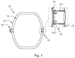
- a hydrogen tank 10 comprises an outer enclosure 12, an inner enclosure 14 positioned in the outer enclosure 12, thermal insulation between the outer and inner enclosures 12, 14 as well as two diametrically opposed connecting systems 16, 16', connecting the outer and inner enclosures 12, 14.
- the inner enclosure 14 contracts much more than the outer enclosure 12. Consequently, at least one of the two connecting systems 16 is configured to allow movement of the inner enclosure 14 relative to the outer enclosure 12 in a direction of movement.
- a first 16' link system (the one on the left on the figure 1 ) is rigid and does not allow any relative movement between the outer and inner enclosures 12, 14 while a second connection system 16 (the one on the right on the figure 1 ) allows relative movement between the outer and inner enclosures 12, 14.
- This second connection system 16 comprises a female sleeve 18.1 secured to the outer enclosure 12 as well as a male sleeve 18.2 secured to the internal enclosure 14 and configured to slide in the female sleeve 18.1.
- These two female and male sleeves 18.1, 18.2 are coaxial and have axes coincident with the direction of movement.
- the present invention aims to remedy all or part of the drawbacks of the prior art.
- the subject of the invention is a tank comprising an external enclosure, an internal enclosure positioned in the external enclosure as well as first and second connecting systems, diametrically opposed, connecting the external and internal enclosures, the external and internal enclosures moving relative to each other in a direction of movement in operation.
- At least one of the first and second connecting systems comprises a central part connected to a first element from among the outer enclosure and the inner enclosure as well as at least three blades distributed around the central part, each blade extending between a first end connected to the central part and a second end which has a head connected to a second element, different from the first element, among the external enclosure and the internal enclosure, each blade being flexible enough to deform elastically between its first and second ends in the direction of movement.
- the blades of the connection system thanks to their ability to deform elastically, allow the external and internal enclosures to move relative to each other according to the direction of movement (in particular due to the phenomena of expansion) while ensuring the absorption of radial forces between the outer and inner enclosures. Moreover, in the presence of hydrogen in the cryogenic state in the internal containment, the latter deviates from the external containment in line with the connection system due to the retraction of the internal containment linked to the reduction in its temperature.
- the profile of the blades is curved and such that the blades are positioned substantially in a transverse plane when the internal enclosure has contracted due to the presence of hydrogen in the cryogenic state in said internal enclosure, makes it possible to limit the stresses in the blades, in the presence of hydrogen in the cryogenic state in the internal enclosure, to a much lower level than if the blades did not have such a curved profile.
- this curved profile thus allows the blades to deform without high stresses during the retraction of the internal enclosure. It also allows the blades to deform without high stresses when the temperature of the blades decreases under the effect of thermal conduction from the internal enclosure containing hydrogen in the cryogenic state.
- the central part is connected to the internal enclosure, each head being connected to the external enclosure.
- the central part comprises a support integral with the internal enclosure, a ring connected to the external enclosure via the blades and configured to be positioned around the support as well as a fastening system configured to immobilize the ring with respect to the support at least along the direction of movement, the connection system comprising first and second dissociable parts, the first part comprising the ring, the blades as well as the heads, the second part comprising the support.
- the support comprises a base fixed to the internal enclosure by fastening elements as well as a tubular portion integral with the base, having an axis substantially coinciding with the direction of movement and on which the ring.
- the fastening system comprises a threaded section provided at the level of the tubular portion as well as a nut configured to be screwed onto the threaded section.
- the fastening system comprises a system for locking the nut in rotation and/or a compression ring inserted between the nut and the ring and/or two shear rings positioned on either side of the ring.
- the outer enclosure comprises an opening in line with the support as well as a cover to close off the opening.
- the external enclosure comprises, for each head, a clip with a U-section, comprising a base against which the head is fixed, positioned in a substantially transverse plane, as well as legs connecting the base to the enclosure external.
- connection system comprises a safety system comprising a female sleeve secured to the outer enclosure which has an axis coinciding with the direction of movement as well as a male extension secured to the internal enclosure, positioned in the female sleeve, the male extension and the female sleeve being dimensioned so that there is clearance all around the male extension between the female sleeve and the male extension when the blades are not damaged.
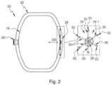
- a reservoir 20 comprises an external enclosure 22, an internal enclosure 24 positioned in the external enclosure 22 as well as first and second connecting systems 26, 26', diametrically opposed, connecting the external and internal enclosures 22, 24.
- the tank 20 is suitable for storing hydrogen in the cryogenic state in the internal enclosure 24.
- the tank 20 comprises thermal insulation between the external and internal enclosures 22, 24.
- the second connection system 26' is rigid and identical to the rigid connection system of the prior art. According to a second configuration, the first and second connection systems 26, 26' are identical.
- a longitudinal direction is parallel to the direction of movement DD.
- a radial direction is perpendicular to the direction of movement DD.
- a transverse plane is a plane perpendicular to the direction of movement DD.
- a longitudinal plane contains the direction of movement DD.
- the connection system 26 comprises a central part 28 connected to a first element from among the outer enclosure 22 and the inner enclosure 24, several blades 30 which each extend between first and second ends, for each blade 30 the first end being connected to the central part 28, the second end having a head 32 connected to a second element, different from the first element, among the outer enclosure 22 and the inner enclosure 24.
- Each blade 30 is radial. By radial blade, it is meant that the blade 30 is oriented in an approximately radial direction, its first and second ends being positioned in a longitudinal plane. According to this arrangement, the head 32 is offset with respect to the central part 28 along a direction comprising a component perpendicular to the direction of displacement DD.
- Each blade 30 is in the form of a strip of material. It is flexible enough to deform elastically between its first and second ends in the direction of displacement DD.
- the central part 28 is connected to the internal enclosure 24 and each head 32 is connected to the external enclosure 22.
- the outer enclosure 22 comprises a clip 34 with a U-shaped section, comprising a base 34.1 against which is fixed a head 32, positioned in a substantially transverse plane as well as legs 34.2 connecting the base 34.1 to the outer enclosure 22.
- each head 32 is connected to a fastener 34 by at least one fastening element 36 such as a screw, a bolt, a rivet or the like.
- the central part 28 comprises a support 38 secured to the internal enclosure 24, a ring 40 connected to the external enclosure 22 via blades 30 and configured to be positioned around the support 38 as well as a fixing system 42 configured to immobilize the ring 40 relative to the support 38 at least in the direction of movement DD.
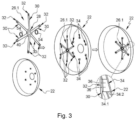
- the connection system 26 comprises first and second parts 26.1, 26.2 that can be dissociated.
- the first part 26.1 visible on the picture 3 , includes the ring 40, the blades 30 and the heads 32 which form a single piece.
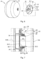
- the second part 26.2 visible on the figure 4 , includes bracket 38.
- the support 38 comprises a base 38.1 fixed to the internal enclosure 24 by fastening elements 44, such as bolts or rivets for example, as well as a tubular portion 38.2 secured to the base 38.1, having a axis A38 substantially coinciding with the direction of movement DD and on which the ring 40 is fitted.
- the base 38.1 and the tubular portion 38.2 form only one and the same piece.
- the support 38 can comprise a counter-plate positioned in the internal enclosure 24 and connected to the base 38.1 by the fixing elements 44.
- the support 38 can be metallic or made of a composite material.
- the ring 40 is substantially flat and positioned in operation in a transverse plane. It has an inside diameter substantially equal to or very slightly greater than the outside diameter of the tubular portion 38.2.
- the first part 26.1 comprising the ring 40, the blades 30 as well as the heads 32, can be metallic or made of a composite material.
- the first part 26.1 and more particularly the blades 30 are curved, the heads 32 being offset towards the internal enclosure 24 with respect to the central part 28 in the absence of constraints and being arranged substantially in the same transverse plane as the part central 28 in the presence of operating constraints.
- the blades 30 have a curved profile. In the presence of hydrogen in the internal enclosure 24, the latter deviates from the external enclosure 22 to the right of the connection system 26.
- the curved profile of the blades 30 is determined so that the blades 30 are positioned in a transverse plane, as illustrated in part (B) of the figure 9 , when the internal enclosure 24 has contracted due to the presence of hydrogen in the cryogenic state in said internal enclosure 24.
- connection system 26 comprises six blades 30 regularly distributed over the periphery of the central part 28.
- the invention is not limited to this number of blades 30.
- the connection system 26 can comprise nine blades 30, as shown in part (A) of the figure 10 , or three blades 30, as illustrated in part (C) of the figure 10 .
- the connection system 26 comprises at least three blades 30 regularly distributed around the central part 28.
- the fixing system 42 comprises a threaded section 46 provided on the outer cylindrical surface of the tubular portion 38.2 as well as a nut 48 configured to be screwed onto the threaded section 46.
- the fixing system 42 comprises a system of rotation blocking 50 of the nut 48 cooperating with the latter to immobilize it in rotation and/or a compression ring 52 inserted between the nut 48 and the ring 40.
- the fastening system 42 comprises two shear rings 54 positioned on either side of the ring 40, one of them being inserted between the base 38.1 of the support 38 and the ring 40, the other being interposed between the compression ring 52 and the ring 40.
- the outer enclosure 22 comprises an opening 56 in line with the support 38 as well as a cover 58 to close the opening 56.
- the opening 56 is dimensioned to allow the setting place of the fastening system 42 from the outside of the outer enclosure 22.
- a method of mounting tank 20 is illustrated in the figures 3 to 8 .
- the first part 26.1 is put in place by connecting each of the heads 32 to the corresponding fastener 34 using the fixing elements 36, as illustrated in the picture 3 .
- the base 38.1 of the support 38 is fixed to the internal enclosure 24 thanks to the fixing elements 44, as illustrated in the figure 4 .
- the internal enclosure 24 is positioned in the external enclosure 22 by positioning the ring 40 of the first part 26.1 around the tubular portion 38.2 of the support 38, as illustrated in the figure 5 And 6 .
- the latter is made in two parts which are assembled after the installation of the internal enclosure 24.
- the components of the fastening system 42 are introduced via the opening 56 and put in place to immobilize the ring 40 with respect to the support 38 in the direction of movement DD.
- the opening 56 is closed by fixing the cover 58 to the outer enclosure 22 all around the opening 56 by any suitable means, such as by welding for example.
- the blades 30 of the connection system 26 allow the outer and inner enclosures 22, 24 to move relative to each other in the direction of movement DD due to expansion phenomena. In addition, the blades 30 take up the radial forces (oriented perpendicular to the direction of movement DD) between the outer and inner enclosures 22, 24.
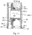
- connection system 26 comprises a safety system 60 allowing the outer enclosure 22 to support the inner enclosure 24 in the event of the blades 30 breaking.
- This connection system 26 comprises a female sleeve 60.1 secured to the outer enclosure 22, more particularly its cover 58, having an axis A60.1 coinciding with the direction of movement DD as well as a male extension 60.2, integral with the internal enclosure 24, configured to be positioned in the female sleeve 60.1.
- the female sleeve 60.1 and the male extension 60.2 are dimensioned so that in the absence of contraction of the internal enclosure 24, the male extension 60.2 does not interfere with the cover 58 and that in presence of a contraction of the internal enclosure 24, part of the male extension 60.2 is still positioned in the female sleeve 60.1.
- the female sleeve 60.1 and the male extension 60.2 are also dimensioned so that there remains a clearance all around the male extension 60.2 between the latter and the female sleeve 60.1, when the blades 30 are not damaged, for that the security system 60 does not induce any friction between the female sleeve 60.1 and the male extension 60.2.
- the male extension 60.2 can be an extension of the support 38, more particularly of its tubular portion 38.2.
- the male extension 60.2 is a separate tube from the support 38 fitted into the tubular portion 38.2 of the support 38.
Landscapes
- Engineering & Computer Science (AREA)
- Mechanical Engineering (AREA)
- General Engineering & Computer Science (AREA)
- Physics & Mathematics (AREA)
- Thermal Sciences (AREA)
- Filling Or Discharging Of Gas Storage Vessels (AREA)
Abstract
L'invention a pour objet un réservoir à double paroi comprenant au moins un système de liaison (26, 26') reliant les enceintes externe et interne (22, 24) du réservoir et comportant une partie centrale (28) reliée à l'enceinte interne (24) ainsi qu'au moins trois lames (30) réparties autour de la partie centrale (28), chaque lame (30) s'étendant entre une première extrémité reliée à la partie centrale (28) et une deuxième extrémité qui présente une tête (32) reliée à l'enceinte externe (22), chaque lame (30) étant suffisamment souple pour se déformer de manière élastique entre ses première et deuxième extrémités selon une direction de déplacement (DD).Ainsi, en fonctionnement, les lames (30) souples autorisent les enceintes externe et interne (22, 24) à se déplacer l'une par rapport à l'autre selon la direction de déplacement (DD) en raison de phénomènes de dilatation tout en assurant la reprise des efforts radiaux entre les enceintes externe et interne (22, 24).The subject of the invention is a double-walled tank comprising at least one connection system (26, 26') connecting the external and internal enclosures (22, 24) of the tank and comprising a central part (28) connected to the enclosure internal (24) as well as at least three blades (30) distributed around the central part (28), each blade (30) extending between a first end connected to the central part (28) and a second end which has a head (32) connected to the outer enclosure (22), each blade (30) being flexible enough to deform elastically between its first and second ends in a direction of displacement (DD).Thus, in operation, the flexible blades (30) allow the outer and inner enclosures (22, 24) to move relative to each other in the direction of movement (DD) due to expansion phenomena while ensuring the absorption of radial forces between the outer and inner enclosures (22, 24).
Description
La présente demande se rapporte à un réservoir comprenant des enceintes interne et externe ainsi qu'au moins un système de liaison à lames radiales souples reliant lesdites enceintes.The present application relates to a tank comprising internal and external enclosures as well as at least one connection system with flexible radial blades connecting said enclosures.
Selon un mode de réalisation visible sur la
Ce deuxième système de liaison 16 comprend un manchon femelle 18.1 solidaire de l'enceinte externe 12 ainsi qu'un manchon mâle 18.2 solidaire de l'enceinte interne 14 et configuré pour coulisser dans le manchon femelle 18.1. Ces deux manchons femelle et mâle 18.1, 18.2 sont coaxiaux et présentent des axes confondus avec la direction de déplacement.This
Ce mode de réalisation n'est pas pleinement satisfaisant en raison des risques de coincement causés par les frottements entre les manchons femelle et mâle 18.1, 18.2 ainsi que du caractère aléatoire des contacts entre les manchons femelle et mâle 18.1, 18.2.This embodiment is not fully satisfactory because of the risks of jamming caused by friction between the female and male sleeves 18.1, 18.2 as well as the random nature of the contacts between the female and male sleeves 18.1, 18.2.
La présente invention vise à remédier à tout ou partie des inconvénients de l'art antérieur.The present invention aims to remedy all or part of the drawbacks of the prior art.
A cet effet, l'invention a pour objet un réservoir comprenant une enceinte externe, une enceinte interne positionnée dans l'enceinte externe ainsi que des premier et deuxième systèmes de liaison, diamétralement opposés, reliant les enceintes externe et interne, les enceintes externe et interne se déplaçant l'une par rapport à l'autre selon une direction de déplacement en fonctionnement.To this end, the subject of the invention is a tank comprising an external enclosure, an internal enclosure positioned in the external enclosure as well as first and second connecting systems, diametrically opposed, connecting the external and internal enclosures, the external and internal enclosures moving relative to each other in a direction of movement in operation.
Au moins un des premier et deuxième systèmes de liaison comprend une partie centrale reliée à un premier élément parmi l'enceinte externe et l'enceinte interne ainsi qu'au moins trois lames réparties autour de la partie centrale, chaque lame s'étendant entre une première extrémité reliée à la partie centrale et une deuxième extrémité qui présente une tête reliée à un deuxième élément, différent du premier élément, parmi l'enceinte externe et l'enceinte interne, chaque lame étant suffisamment souple pour se déformer de manière élastique entre ses première et deuxième extrémités selon la direction de déplacement.At least one of the first and second connecting systems comprises a central part connected to a first element from among the outer enclosure and the inner enclosure as well as at least three blades distributed around the central part, each blade extending between a first end connected to the central part and a second end which has a head connected to a second element, different from the first element, among the external enclosure and the internal enclosure, each blade being flexible enough to deform elastically between its first and second ends in the direction of movement.
Selon l'invention, les lames sont courbes et ont un profil tel que les têtes sont :
- décalées vers l'enceinte interne par rapport à la partie centrale en l'absence de contraintes, l'absence de contraintes correspondant à l'absence d'hydrogène dans l'enceinte interne, et
- disposées sensiblement dans un même plan transversal que la partie centrale en présence de contraintes, en fonctionnement, la présence de contraintes correspondant à la présence d'hydrogène à l'état cryogénique dans l'enceinte interne.
- shifted towards the inner enclosure relative to the central part in the absence of stresses, the absence of stresses corresponding to the absence of hydrogen in the inner enclosure, and
- arranged substantially in the same transverse plane as the central part in the presence of stresses, in operation, the presence of stresses corresponding to the presence of hydrogen in the cryogenic state in the internal enclosure.
Les lames du système de liaison, grâce à leur capacité à se déformer de manière élastique, permettent aux enceintes externe et interne de se déplacer l'une par rapport à l'autre selon la direction de déplacement (notamment en raison des phénomènes de dilatation) tout en assurant la reprise des efforts radiaux entre les enceintes externe et interne. De plus, en présence d'hydrogène à l'état cryogénique dans l'enceinte interne, cette dernière s'écarte de l'enceinte externe au droit du système de liaison du fait de la rétractation de l'enceinte interne liée à la diminution de sa température. Le fait que le profil des lames soit courbe et tel que les lames sont positionnées sensiblement dans un plan transversal lorsque l'enceinte interne s'est contractée en raison de la présence d'hydrogène à l'état cryogénique dans ladite enceinte interne, permet de limiter les contraintes dans les lames, en présence d'hydrogène à l'état cryogénique dans l'enceinte interne, à un niveau beaucoup plus faible que si les lames n'avaient pas un tel profil courbe. En effet, ce profil courbe permet ainsi au lames de se déformer sans contraintes élevées lors de la rétractation de l'enceinte interne. Il permet également aux lames de se déformer sans contraintes élevées lorsque la température des lames diminue sous l'effet d'une conduction thermique depuis l'enceinte interne contenant de l'hydrogène à l'état cryogénique.The blades of the connection system, thanks to their ability to deform elastically, allow the external and internal enclosures to move relative to each other according to the direction of movement (in particular due to the phenomena of expansion) while ensuring the absorption of radial forces between the outer and inner enclosures. Moreover, in the presence of hydrogen in the cryogenic state in the internal containment, the latter deviates from the external containment in line with the connection system due to the retraction of the internal containment linked to the reduction in its temperature. The fact that the profile of the blades is curved and such that the blades are positioned substantially in a transverse plane when the internal enclosure has contracted due to the presence of hydrogen in the cryogenic state in said internal enclosure, makes it possible to limit the stresses in the blades, in the presence of hydrogen in the cryogenic state in the internal enclosure, to a much lower level than if the blades did not have such a curved profile. Indeed, this curved profile thus allows the blades to deform without high stresses during the retraction of the internal enclosure. It also allows the blades to deform without high stresses when the temperature of the blades decreases under the effect of thermal conduction from the internal enclosure containing hydrogen in the cryogenic state.
Selon une autre caractéristique, la partie centrale est reliée à l'enceinte interne, chaque tête étant reliée à l'enceinte externe.According to another characteristic, the central part is connected to the internal enclosure, each head being connected to the external enclosure.
Selon une autre caractéristique, la partie centrale comporte un support solidaire de l'enceinte interne, un anneau relié à l'enceinte externe par l'intermédiaire des lames et configuré pour être positionné autour du support ainsi qu'un système de fixation configuré pour immobiliser l'anneau par rapport au support au moins selon la direction de déplacement, le système de liaison comportant des première et deuxième parties dissociables, la première partie comportant l'anneau, les lames ainsi que les têtes, la deuxième partie comportant le support. Selon une autre caractéristique, le support comprend une embase fixée sur l'enceinte interne par des éléments de fixation ainsi qu'une portion tubulaire solidaire de l'embase, présentant un axe sensiblement confondu avec la direction de déplacement et sur laquelle est emmanché l'anneau.According to another characteristic, the central part comprises a support integral with the internal enclosure, a ring connected to the external enclosure via the blades and configured to be positioned around the support as well as a fastening system configured to immobilize the ring with respect to the support at least along the direction of movement, the connection system comprising first and second dissociable parts, the first part comprising the ring, the blades as well as the heads, the second part comprising the support. According to another characteristic, the support comprises a base fixed to the internal enclosure by fastening elements as well as a tubular portion integral with the base, having an axis substantially coinciding with the direction of movement and on which the ring.
Selon une autre caractéristique, le système de fixation comprend un tronçon fileté prévu au niveau de la portion tubulaire ainsi qu'un écrou configuré pour se visser sur le tronçon fileté. Selon une autre caractéristique, le système de fixation comprend un système de blocage en rotation de l'écrou et/ou une bague de compression intercalée entre l'écrou et l'anneau et/ou deux bagues de cisaillement positionnées de part et d'autre de l'anneau.According to another characteristic, the fastening system comprises a threaded section provided at the level of the tubular portion as well as a nut configured to be screwed onto the threaded section. According to another characteristic, the fastening system comprises a system for locking the nut in rotation and/or a compression ring inserted between the nut and the ring and/or two shear rings positioned on either side of the ring.
Selon une autre caractéristique, l'enceinte externe comprend une ouverture au droit du support ainsi qu'un couvercle pour obturer l'ouverture.According to another feature, the outer enclosure comprises an opening in line with the support as well as a cover to close off the opening.
Selon une autre caractéristique, l'enceinte externe comprend, pour chaque tête, une attache avec une section en U, comportant une base contre laquelle est fixée la tête, positionnée dans un plan sensiblement transversal ainsi que des jambes reliant la base à l'enceinte externe.According to another characteristic, the external enclosure comprises, for each head, a clip with a U-section, comprising a base against which the head is fixed, positioned in a substantially transverse plane, as well as legs connecting the base to the enclosure external.
Selon une autre caractéristique, le système de liaison comprend un système de sécurité comportant un manchon femelle solidaire de l'enceinte externe qui présente un axe confondu avec la direction de déplacement ainsi qu'une extension mâle solidaire de l'enceinte interne, positionnée dans le manchon femelle, l'extension mâle et le manchon femelle étant dimensionnés de manière à ce qu'il subsiste un jeu tout autour de l'extension mâle entre le manchon femelle et l'extension mâle lorsque les lames ne sont pas endommagées.According to another characteristic, the connection system comprises a safety system comprising a female sleeve secured to the outer enclosure which has an axis coinciding with the direction of movement as well as a male extension secured to the internal enclosure, positioned in the female sleeve, the male extension and the female sleeve being dimensioned so that there is clearance all around the male extension between the female sleeve and the male extension when the blades are not damaged.
D'autres caractéristiques et avantages ressortiront de la description de l'invention qui va suivre, description donnée à titre d'exemple uniquement, en regard des dessins annexés parmi lesquels :
- La
figure 1 est une représentation schématique d'un réservoir et d'un système de liaison illustrant un mode de réalisation de l'art antérieur, - La
figure 2 est une représentation schématique d'un réservoir et d'un système de liaison illustrant un mode de réalisation de l'invention, - La
figure 3 est une vue en perspective d'une partie d'une enceinte externe et d'une première partie d'un système de liaison à différentes étapes de montage illustrant un mode de réalisation de l'invention, - La
figure 4 est une vue en perspective d'une partie d'une enceinte interne et d'une deuxième partie d'un système de liaison illustrant un mode de réalisation de l'invention, - La
figure 5 est une vue en perspective des enceintes interne et externe visibles sur lesfigures 3 et4 préalablement à leur assemblage illustrant un mode de réalisation de l'invention, - La
figure 6 est une vue en perspective d'une partie d'un réservoir après l'insertion de l'enceinte interne dans l'enceinte externe illustrant un mode de réalisation de l'invention, - La
figure 7 est une coupe longitudinale des première et deuxième parties du système de liaison, visibles sur lesfigures 3 et4 , assemblées illustrant un mode de réalisation de l'invention, - La
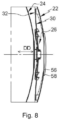
figure 8 est une coupe longitudinale d'une partie d'un réservoir illustrant un mode de réalisation de l'invention, - La
figure 9 est une représentation schématique de deux systèmes de liaison ayant des profils différents illustrant deux modes de réalisation de l'invention, - La
figure 10 est une représentation schématique de plusieurs systèmes de liaison illustrant plusieurs modes de réalisation de l'invention, et - La
figure 11 est une coupe longitudinale d'une partie d'un système de liaison illustrant un autre mode de réalisation de l'invention.
- There
figure 1 is a schematic representation of a tank and a connection system illustrating an embodiment of the prior art, - There
figure 2 is a schematic representation of a tank and a connection system illustrating an embodiment of the invention, - There
picture 3 is a perspective view of part of an outer enclosure and of a first part of a connection system at different stages of assembly illustrating an embodiment of the invention, - There
figure 4 is a perspective view of part of an internal enclosure and of a second part of a connection system illustrating an embodiment of the invention, - There
figure 5 is a perspective view of the internal and external enclosures visible on thefigure 3 And4 prior to their assembly illustrating an embodiment of the invention, - There
figure 6 is a perspective view of part of a tank after insertion of the inner enclosure into the outer enclosure illustrating one embodiment of the invention, - There
figure 7 is a longitudinal section of the first and second parts of the connection system, visible on thefigure 3 And4 , assemblies illustrating an embodiment of the invention, - There
figure 8 is a longitudinal section of part of a tank illustrating an embodiment of the invention, - There
figure 9 is a schematic representation of two connection systems having different profiles illustrating two embodiments of the invention, - There
figure 10 is a schematic representation of several link systems illustrating several embodiments of the invention, and - There
figure 11 is a longitudinal section of part of a link system illustrating another embodiment of the invention.
Selon un mode de réalisation visible sur la
Selon une application, le réservoir 20 est adapté pour stocker de l'hydrogène à l'état cryogénique dans l'enceinte interne 24. Selon cette application, le réservoir 20 comprend une isolation thermique entre les enceintes externe et interne 22, 24.According to one application, the
Les enceintes externe et interne ainsi que l'isolation thermique ne sont pas plus décrites car elles peuvent être identiques à celles de l'art antérieur.The external and internal enclosures as well as the thermal insulation are not further described because they may be identical to those of the prior art.
Selon une première configuration, le deuxième système de liaison 26' est rigide et identique au système de liaison rigide de l'art antérieur. Selon une deuxième configuration, les premier et deuxième systèmes de liaison 26, 26' sont identiques.According to a first configuration, the second connection system 26' is rigid and identical to the rigid connection system of the prior art. According to a second configuration, the first and
En fonctionnement, au droit du premier système de liaison 26, les enceintes externe et interne 22, 24 peuvent se déplacer l'une par rapport à l'autre selon une direction de déplacement DD en raison des phénomènes de dilatation différents des enceintes externe et interne 22, 24. Pour la suite de la description, une direction longitudinale est parallèle à la direction de déplacement DD. Une direction radiale est perpendiculaire à la direction de déplacement DD. Un plan transversal est un plan perpendiculaire à la direction de déplacement DD. Un plan longitudinal contient la direction de déplacement DD.In operation, in line with the
Le système de liaison 26 comprend une partie centrale 28 reliée à un premier élément parmi l'enceinte externe 22 et l'enceinte interne 24, plusieurs lames 30 qui s'étendent chacune entre des première et deuxième extrémités, pour chaque lame 30 la première extrémité étant reliée à la partie centrale 28, la deuxième extrémité présentant une tête 32 reliée à un deuxième élément, différent du premier élément, parmi l'enceinte externe 22 et l'enceinte interne 24. Chaque lame 30 est radiale. Par lame radiale, on entend que la lame 30 est orientée selon une direction approximativement radiale, ses première et deuxième extrémités étant positionnées dans un plan longitudinal. Selon cet agencement, la tête 32 est décalée par rapport à la partie centrale 28 selon une direction comportant une composante perpendiculaire à la direction de déplacement DD.The
Chaque lame 30 se présente sous la forme d'une bande de matière. Elle est suffisamment souple pour se déformer de manière élastique entre ses première et deuxième extrémités selon la direction de déplacement DD.Each
Selon un agencement, la partie centrale 28 est reliée à l'enceinte interne 24 et chaque tête 32 est reliée à l'enceinte externe 22.According to one arrangement, the
Comme illustré sur la
Selon une configuration, chaque tête 32 est reliée à une attache 34 par au moins un élément de fixation 36 comme une vis, un boulon, un rivet ou autres.According to one configuration, each
Selon un mode de réalisation, la partie centrale 28 comporte un support 38 solidaire de l'enceinte interne 24, un anneau 40 relié à l'enceinte externe 22 par l'intermédiaire des lames 30 et configuré pour être positionné autour du support 38 ainsi qu'un système de fixation 42 configuré pour immobiliser l'anneau 40 par rapport au support 38 au moins selon la direction de déplacement DD. Ainsi, le système de liaison 26 comprend des première et deuxième parties 26.1, 26.2 dissociables.According to one embodiment, the
Selon ce mode de réalisation, la première partie 26.1, visible sur la
Selon une configuration, le support 38 comprend une embase 38.1 fixée sur l'enceinte interne 24 par des éléments de fixation 44, comme des boulons ou des rivets par exemple, ainsi qu'une portion tubulaire 38.2 solidaire de l'embase 38.1, présentant un axe A38 sensiblement confondu avec la direction de déplacement DD et sur laquelle est emmanché l'anneau 40. L'embase 38.1 et la portion tubulaire 38.2 ne forment qu'une seule et même pièce.According to one configuration, the
Le support 38 peut comprendre une contre-plaque positionnée dans l'enceinte interne 24 et reliée à l'embase 38.1 par les éléments de fixation 44.The
Le support 38 peut être métallique ou réalisé en matériau composite.The
L'anneau 40 est sensiblement plat et positionné en fonctionnement dans un plan transversal. Il présente un diamètre intérieur sensiblement égal ou très légèrement supérieur au diamètre extérieur de la portion tubulaire 38.2.The
La première partie 26.1, comprenant l'anneau 40, les lames 30 ainsi que les têtes 32, peut être métallique ou réalisée en matériau composite.The first part 26.1, comprising the
Comme illustré sur la partie (A) de la
Comme illustré sur les
Selon un mode de réalisation visible sur la
Selon un mode de réalisation visible sur les
Pour permettre la mise en place du système de fixation 42, l'enceinte externe 22 comprend une ouverture 56 au droit du support 38 ainsi qu'un couvercle 58 pour obturer l'ouverture 56. L'ouverture 56 est dimensionnée pour permettre la mise en place du système de fixation 42 depuis l'extérieur de l'enceinte externe 22.To allow the installation of the fixing
Un procédé de montage du réservoir 20 est illustré sur les
Après avoir réalisé les enceintes externe et interne 22, 24, la première partie 26.1 est mise en place en reliant chacune des têtes 32 à l'attache 34 correspondante grâce aux éléments de fixation 36, comme illustré sur la
En suivant, l'enceinte interne 24 est positionnée dans l'enceinte externe 22 en positionnant l'anneau 40 de la première partie 26.1 autour de la portion tubulaire 38.2 du support 38, comme illustré sur les
Les composants du système de fixation 42 sont introduits via l'ouverture 56 et mis en place pour immobiliser l'anneau 40 par rapport au support 38 selon la direction de déplacement DD.The components of the
Enfin, l'ouverture 56 est fermée en fixant le couvercle 58 sur l'enceinte externe 22 tout autour de l'ouverture 56 par tout moyen approprié, comme par soudage par exemple.Finally, the
Les lames 30 du système de liaison 26 permettent aux enceintes externe et interne 22, 24 de se déplacer l'une par rapport à l'autre selon la direction de déplacement DD en raison des phénomènes de dilatation. En complément, les lames 30 assurent la reprise des efforts radiaux (orientés perpendiculairement à la direction de déplacement DD) entre les enceintes externe et interne 22, 24.The
Selon un mode de réalisation visible sur la
Claims (9)
caractérisé en ce que les lames (30) sont courbes et ont un profil tel que les têtes (32) sont :
characterized in that the blades (30) are curved and have a profile such that the heads (32) are:
Applications Claiming Priority (1)
| Application Number | Priority Date | Filing Date | Title |
|---|---|---|---|
| FR2201665 | 2022-02-25 |
Publications (1)
| Publication Number | Publication Date |
|---|---|
| EP4235012A1 true EP4235012A1 (en) | 2023-08-30 |
Family
ID=81448915
Family Applications (1)
| Application Number | Title | Priority Date | Filing Date |
|---|---|---|---|
| EP23156204.2A Pending EP4235012A1 (en) | 2022-02-25 | 2023-02-13 | Tank comprising inner and outer enclosures and at least one system for connecting flexible radial strips connecting said enclosures |
Country Status (2)
| Country | Link |
|---|---|
| US (1) | US12078293B2 (en) |
| EP (1) | EP4235012A1 (en) |
Citations (6)
| Publication number | Priority date | Publication date | Assignee | Title |
|---|---|---|---|---|
| US3241705A (en) * | 1963-08-19 | 1966-03-22 | Air Reduction | Container |
| US3446388A (en) * | 1966-04-15 | 1969-05-27 | Ryan Ind Inc | Cryogenic tank support means |
| CA2441775A1 (en) * | 2003-09-23 | 2003-11-17 | Westport Research Inc. | Container for holding a cryogenic fluid |
| WO2014015969A1 (en) * | 2012-07-25 | 2014-01-30 | Ziemann International GmbH | Transport container for cryogenic fluids |
| WO2014161899A1 (en) * | 2013-04-05 | 2014-10-09 | Cryoshelter Gmbh | Suspension system for an inner container mounted for thermal insulation in an outer container and container arrangement |
| WO2017190846A1 (en) * | 2016-05-04 | 2017-11-09 | Linde Aktiengesellschaft | Transport container |
Family Cites Families (5)
| Publication number | Priority date | Publication date | Assignee | Title |
|---|---|---|---|---|
| US3481505A (en) * | 1967-05-24 | 1969-12-02 | Process Eng Inc | Support system for cryogenic containers (1) |
| US3764036A (en) * | 1970-12-02 | 1973-10-09 | Ametek Inc | Cryogenic liquid storage systems |
| US3696959A (en) * | 1971-01-11 | 1972-10-10 | Lox Equip | Cryogenic storage vessel constructed of dissimilar materials |
| US6015106A (en) * | 1998-09-01 | 2000-01-18 | 3M Innovative Properties Company | Apparatus for controllably breaking hollow spheres |
| GB2452910B (en) * | 2007-09-18 | 2012-11-21 | T Baden Hardstaff Ltd | Storage tank assembly |
-
2023
- 2023-02-13 EP EP23156204.2A patent/EP4235012A1/en active Pending
- 2023-02-21 US US18/172,079 patent/US12078293B2/en active Active
Patent Citations (6)
| Publication number | Priority date | Publication date | Assignee | Title |
|---|---|---|---|---|
| US3241705A (en) * | 1963-08-19 | 1966-03-22 | Air Reduction | Container |
| US3446388A (en) * | 1966-04-15 | 1969-05-27 | Ryan Ind Inc | Cryogenic tank support means |
| CA2441775A1 (en) * | 2003-09-23 | 2003-11-17 | Westport Research Inc. | Container for holding a cryogenic fluid |
| WO2014015969A1 (en) * | 2012-07-25 | 2014-01-30 | Ziemann International GmbH | Transport container for cryogenic fluids |
| WO2014161899A1 (en) * | 2013-04-05 | 2014-10-09 | Cryoshelter Gmbh | Suspension system for an inner container mounted for thermal insulation in an outer container and container arrangement |
| WO2017190846A1 (en) * | 2016-05-04 | 2017-11-09 | Linde Aktiengesellschaft | Transport container |
Also Published As
| Publication number | Publication date |
|---|---|
| US20230272879A1 (en) | 2023-08-31 |
| US12078293B2 (en) | 2024-09-03 |
Similar Documents
| Publication | Publication Date | Title |
|---|---|---|
| EP3553331B1 (en) | Device for pivoting connection between at least two parts, aircraft comprising a cowl equipped with said pivoting connection device | |
| EP0604312B1 (en) | Elastic ring with make-up witness for joint | |
| EP1950392B1 (en) | Device for assembling two units, for example for a turbomachine stator | |
| FR2919691A1 (en) | Anchoring screw fastener for temporary fixation of drilling grid on wings of airplane, has assembly of rod and half clamps in form of circle, whose diameter is identical to internal diameter of orifices for longitudinal sliding of assembly | |
| FR2847623A1 (en) | Two-piece washer for minimizing bending of bolt, has convex and concave surfaces of outer and inner annular washer elements which contact with each other and move relative to each other so that respective axes assume non-coaxial positions | |
| FR2923541A1 (en) | DISCHARGE VALVE IN A TURBOMACHINE | |
| EP3521174A1 (en) | Assembly for an aircraft engine attachment comprising a hinge pin supported by a yoke and immobile in translation | |
| FR2893367A1 (en) | System for locking aircraft engine mounting rod in clevis joint comprises plates which fit between ends of rod and nut and bolt head, plates having studs which fit into bores in rod ends to fix them in position | |
| FR2899658A1 (en) | CLAMPING DEVICE | |
| CA2777285C (en) | Turbo machine electrical connection element | |
| EP0898551B1 (en) | System for temporarily blocking the relative displacement of two bodies, following at least a preset direction | |
| EP3084140B1 (en) | Guide arm for elements having an elongated shape, in particular for a turbomachine | |
| EP4235012A1 (en) | Tank comprising inner and outer enclosures and at least one system for connecting flexible radial strips connecting said enclosures | |
| EP2003384B1 (en) | Connection system comprising safety attachment means | |
| EP1605195B1 (en) | Pipe coupling system and associated method of assembly | |
| EP0030180A1 (en) | Joining device for pipes | |
| FR2781849A1 (en) | Double section washer to take up play when bolting one piece to an other which clips into the hole of the piece to be fixed | |
| FR2926613A1 (en) | Blower disk for e.g. turbopropeller engine of airplane, has clamps at its external periphery, and bush authorizing pivotment of platform around rod of pin, where ends of bush is in support on head of pin and each clamp during tightening nut | |
| FR2799515A1 (en) | GAME RETRIEVAL SYSTEM FOR ATTACHING TWO PIECES TO EACH OTHER USING A SCREW TYPE FASTENER | |
| FR3094047A3 (en) | Connection between two assembled elements articulated to each other. | |
| EP4215791B1 (en) | Device for connecting two double-walled pipes and hydrogen pipeline comprising said connection device | |
| EP3938667B1 (en) | Pyrotechnic nut releasing device | |
| EP1637747B1 (en) | Arrangement for fixing of an equipment element for a motor vehicle | |
| FR2640349A1 (en) | Collar for fixing piping | |
| FR3146503A1 (en) | Tank comprising internal and external enclosures as well as at least one annular linear connection system connecting said enclosures |
Legal Events
| Date | Code | Title | Description |
|---|---|---|---|
| PUAI | Public reference made under article 153(3) epc to a published international application that has entered the european phase |
Free format text: ORIGINAL CODE: 0009012 |
|
| STAA | Information on the status of an ep patent application or granted ep patent |
Free format text: STATUS: EXAMINATION IS IN PROGRESS |
|
| 17P | Request for examination filed |
Effective date: 20230213 |
|
| AK | Designated contracting states |
Kind code of ref document: A1 Designated state(s): AL AT BE BG CH CY CZ DE DK EE ES FI FR GB GR HR HU IE IS IT LI LT LU LV MC ME MK MT NL NO PL PT RO RS SE SI SK SM TR |
|
| RBV | Designated contracting states (corrected) |
Designated state(s): AL AT BE BG CH CY CZ DE DK EE ES FI FR GB GR HR HU IE IS IT LI LT LU LV MC ME MK MT NL NO PL PT RO RS SE SI SK SM TR |