EP3553331B1 - Device for pivoting connection between at least two parts, aircraft comprising a cowl equipped with said pivoting connection device - Google Patents
Device for pivoting connection between at least two parts, aircraft comprising a cowl equipped with said pivoting connection device Download PDFInfo
- Publication number
- EP3553331B1 EP3553331B1 EP19163514.3A EP19163514A EP3553331B1 EP 3553331 B1 EP3553331 B1 EP 3553331B1 EP 19163514 A EP19163514 A EP 19163514A EP 3553331 B1 EP3553331 B1 EP 3553331B1
- Authority
- EP
- European Patent Office
- Prior art keywords
- branch
- extension
- link device
- face
- pivoting
- Prior art date
- Legal status (The legal status is an assumption and is not a legal conclusion. Google has not performed a legal analysis and makes no representation as to the accuracy of the status listed.)
- Active
Links
- 230000002093 peripheral effect Effects 0.000 claims description 5
- 230000000903 blocking effect Effects 0.000 claims 4
- 230000003190 augmentative effect Effects 0.000 claims 1
- 208000031968 Cadaver Diseases 0.000 description 7
- 230000000712 assembly Effects 0.000 description 1
- 238000000429 assembly Methods 0.000 description 1
- 230000000295 complement effect Effects 0.000 description 1
- 230000005489 elastic deformation Effects 0.000 description 1
- 230000003100 immobilizing effect Effects 0.000 description 1
- 238000003780 insertion Methods 0.000 description 1
- 230000037431 insertion Effects 0.000 description 1
- 239000007787 solid Substances 0.000 description 1
Images
Classifications
-
- B—PERFORMING OPERATIONS; TRANSPORTING
- B64—AIRCRAFT; AVIATION; COSMONAUTICS
- B64D—EQUIPMENT FOR FITTING IN OR TO AIRCRAFT; FLIGHT SUITS; PARACHUTES; ARRANGEMENT OR MOUNTING OF POWER PLANTS OR PROPULSION TRANSMISSIONS IN AIRCRAFT
- B64D29/00—Power-plant nacelles, fairings, or cowlings
- B64D29/06—Attaching of nacelles, fairings or cowlings
-
- B—PERFORMING OPERATIONS; TRANSPORTING
- B64—AIRCRAFT; AVIATION; COSMONAUTICS
- B64D—EQUIPMENT FOR FITTING IN OR TO AIRCRAFT; FLIGHT SUITS; PARACHUTES; ARRANGEMENT OR MOUNTING OF POWER PLANTS OR PROPULSION TRANSMISSIONS IN AIRCRAFT
- B64D29/00—Power-plant nacelles, fairings, or cowlings
- B64D29/08—Inspection panels for power plants
-
- E—FIXED CONSTRUCTIONS
- E05—LOCKS; KEYS; WINDOW OR DOOR FITTINGS; SAFES
- E05D—HINGES OR SUSPENSION DEVICES FOR DOORS, WINDOWS OR WINGS
- E05D5/00—Construction of single parts, e.g. the parts for attachment
- E05D5/10—Pins, sockets or sleeves; Removable pins
- E05D5/12—Securing pins in sockets, movably or not
-
- F—MECHANICAL ENGINEERING; LIGHTING; HEATING; WEAPONS; BLASTING
- F16—ENGINEERING ELEMENTS AND UNITS; GENERAL MEASURES FOR PRODUCING AND MAINTAINING EFFECTIVE FUNCTIONING OF MACHINES OR INSTALLATIONS; THERMAL INSULATION IN GENERAL
- F16C—SHAFTS; FLEXIBLE SHAFTS; ELEMENTS OR CRANKSHAFT MECHANISMS; ROTARY BODIES OTHER THAN GEARING ELEMENTS; BEARINGS
- F16C11/00—Pivots; Pivotal connections
- F16C11/04—Pivotal connections
- F16C11/10—Arrangements for locking
-
- F—MECHANICAL ENGINEERING; LIGHTING; HEATING; WEAPONS; BLASTING
- F16—ENGINEERING ELEMENTS AND UNITS; GENERAL MEASURES FOR PRODUCING AND MAINTAINING EFFECTIVE FUNCTIONING OF MACHINES OR INSTALLATIONS; THERMAL INSULATION IN GENERAL
- F16C—SHAFTS; FLEXIBLE SHAFTS; ELEMENTS OR CRANKSHAFT MECHANISMS; ROTARY BODIES OTHER THAN GEARING ELEMENTS; BEARINGS
- F16C2326/00—Articles relating to transporting
- F16C2326/43—Aeroplanes; Helicopters
Definitions
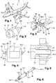
- an aircraft 10 comprises several engine assemblies 12 which are positioned under the wing 14 of the aircraft 10.
- An engine assembly 12 comprises an engine 16, a nacelle 18 positioned around the engine 16 and a mast 20 which provides the connection between the engine 16 and the rest of the aircraft 10, in particular the wing 14.
- the nacelle 18 comprises at least one cover 22 connected to the rest of the nacelle 18 by a hinge 24 allowing the cover 22 to pivot about a pivot axis A24 between an open position (visible on the figure 2 ) and a closed position (visible on the figure 1 ).
- the hinge 24 has several pivoting connection devices 26 distributed along the pivot axis A24.
- Guide rings can be interposed between the cylindrical axis 32 and the branches 28.1, 28.2 of the yoke 28 as well as between the cylindrical axis 32 and the arm 30.
- the pivoting connection device 26 also comprises first and second stops 34, 36, positioned on either side of the branches 28.1, 28.2 of the yoke 28, for immobilize the cylindrical axis 32 in translation relative to the branches 28.1, 28.2 in a direction parallel to the pivot axis A24.
- the cylindrical axis 32 has at a first end a head 38 which forms the first stop 34 and which is configured to bear against the outer face F28.1 of the first branch 28.1 of the yoke 28.
- the second stop 36 is in the form of a split pin 40 which passes through the cylindrical axis 32 and which is configured to bear against the outer face F28.2 of the second branch 28.2 of the yoke 28.
- This first embodiment requires that the two sides of the yoke 28 be accessible in order to be able to assemble the pivoting connection device, the cylindrical axis 32 being introduced from a first side of the yoke 28, the cotter pin being put in place from a second side of the yoke 28.
- Tightening or unscrewing the screw 46 causes the insert 44 to move closer or separate from the head 46.1 of the screw 46.
- the second end of the tubular body 42 is not radially expanded.
- the second end of the tubular body 42 is radially expanded.
- the connecting system is inserted into the bores of the branches 28.1, 28.2 of the yoke 28 and of the arm 30 from a first side of the yoke 28.
- the head 46.1 of the screw 46 and the insert 44 are brought together by screwing the screw 46, from the first side of the yoke 28, so as to cause the expansion of the second end of the tubular body 42.
- the collar 42.1 of the tubular body 42 forms a first stop making it possible to immobilize the tubular body 42 in a first direction.
- the expansion of the second end of the tubular body forms a second stop making it possible to immobilize the tubular body 42 in a second direction, opposite to the first direction.
- the friction between the tubular body 42 and the second branch 28.2 of the yoke 28, due to the radial expansion of the second end of the tubular body also contributes to the immobilization of the tubular body 42 relative to the second branch 28.2.
- This second embodiment allows the assembly of the pivoting connection device from one side of the yoke 28.
- this second embodiment induces significant radial loads at the bore of one of the two branches 28.2 of the yoke 28 due to the expansion of the second end of the tubular body 42.
- the present invention aims to remedy the drawbacks of the prior art.
- the document FR2118756 A5 discloses a connecting device structurally and functionally similar to the subject of claim 1.
- the invention relates to a pivoting connection device connecting at least two parts as claimed in claim 1.
- the pivoting connection device can be assembled from only one side of the yoke.
- the pivoting connection device does not induce any radial load in the bore of one of the branches, unlike the second embodiment of the prior art.
- none of the other parts of the pivoting connection device is subjected to stresses in the blocked state.
- first part 52 is a cowl of an aircraft nacelle and the second part 54 is a nacelle of aircraft.
- a longitudinal direction is a direction parallel to the pivot axis A64.
- a radial direction is perpendicular to the pivot axis A64.
- a longitudinal plane is a plane which passes through the pivot axis A64.
- a transverse plane is a plane perpendicular to the pivot axis A64.
- each branch 58 (or 60) comprises an interior face FI58 (or FI60), oriented towards the other branch 60 (or 58), and an exterior face FE58 (or FE60) opposite to the interior face FI58 (or F60).
- the interior faces FI58, FI60 and the exterior faces FE58, FE60 are mutually parallel and positioned in transverse planes.
- Each branch 58 (or 60) comprises a bore 66 (or 68) which opens out at the level of the interior face FI58 (or FI60) and the exterior face FE58 (or FE60), the bore 66 (or 68) having an axis of revolution perpendicular to the inside face FI58 (or FI60) and to the outside face FE58 (or FE60).
- the arm 62 comprises two lateral faces F62, F62 'parallel to each other and to the pivot axis A64 as well as a bore 70 which opens out at the level of the lateral faces F62, F62', the bore 70 having a perpendicular axis of revolution on the side faces F62, F62 '.
- the cylindrical axis 64 can be solid or hollow. It has a cylindrical peripheral face 72 coaxial with the pivot axis A64, which extends between first and second end faces 74.1, 74.2 substantially perpendicular to the pivot axis A64.
- the pivoting connection device 50 comprises at least one guide ring 76 interposed between one of the branches 58 and the cylindrical axis 64.
- the guide ring 76 comprises a internal diameter, equal to the external diameter of the cylindrical axis 64, and an external diameter equal to the internal diameter of the bore 66 of the first branch 58.
- the bores 66 to 70 of the first and second branches 58, 60 and of the arm 62 comprise guide rings. According to one configuration, only the bores 66, 68 of the first and second branches 58, 60 include guide rings.
- the tubular body 78 and the extension 84 form a single and the same part.
- the tubular body 78 and the extension 84 have identical internal diameters and substantially equal to the external diameter of the cylindrical axis 64.
- the extension 84 comprises an internal face 85 in contact with the peripheral face of the cylindrical axis 64 when the extension 84 is not radially expanded.
- the tubular body 78 has an outside diameter substantially equal to the diameter of the bore 66 of the first branch 58 and greater than that of the extension 84.
- the extension 84 has a small thickness favoring its elastic deformation.
- the flange 80 has a diameter greater than the outer diameter of the tubular body 78. This flange 80 makes it possible to block the guide ring 76 relative to the first branch 58 in the longitudinal direction, in a first direction.
- the extension 84 comprises several slots 86 distributed regularly over the circumference of the extension 84.
- Each slot 86 is parallel to the pivot axis A64 and extends from the second end 84.2 of the extension 84 to approximately the first end 84.1 of the extension 84.
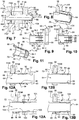
- the pivoting connection device comprises a system 88 for immobilizing the cylindrical axis 64 and the guide ring 76 with respect to one another, configured to occupy a free state, visible on the figure 12A , wherein the cylindrical axis 64 and the guide ring 76 slide relative to each other in a direction parallel to the pivot axis A64, and a blocked state, visible on the figure 12B , wherein the cylindrical axis 64 and the guide ring 76 are immobilized relative to each other in the longitudinal direction, in both directions.
- the immobilization system 88 comprises shapes at the level of the cylindrical axis 64 and of the extension 84 of the guide ring 76 which are configured to cooperate with each other when the immobilization system is. in the blocked state.
- the immobilization system 88 comprises at least one groove 90 which extends over the entire circumference of the peripheral face 72 of the cylindrical axis 64, in a transverse plane.
- the immobilization system 88 comprises at least one rib 92, at the level of the inner face 85 of the extension 84 of the guide ring 76, the shapes of which are complementary to those of the groove 90 of the cylindrical axis 64 .
- the groove 90 and the rib 92 have identical trapezoidal sections and each have two flared side walls 94 (referenced on the figure 12A ) which promote the introduction or exit of the rib 92 of the groove 90.
- the extension 84 is configured to be able to be elastically deformed radially, thanks in particular to the slots 86, to allow the rib 92 to slide on the cylindrical axis 64 (as illustrated in FIG. figure 12A ) when it is not positioned in line with the groove 90 and to enter said groove 90 (as illustrated in figure 12B ) when the rib 92 and the groove 90 are positioned in line with one another.
- the pivoting link device 50 comprises a locking system 96 configured to occupy a disassembled state (visible on the figure 13A ), in which it allows mounting and sliding of the guide ring 76 in the bore 66 of the first branch 58, and a blocked state (visible on the figure 13B ) in which it is in contact with the outer face FE58 of the first branch 58 in order to block the guide ring 76 relative to the first branch 58 in the longitudinal direction, in a second direction opposite to the first direction.
- the locking system 96 and the collar 80 immobilize the guide ring 76 relative to the first branch 58 in the longitudinal direction, in both directions.
- the locking system 96 comprises a thread 98, at the level of the section 82 of the guide ring 76, projecting relative to the exterior face FE58 of the first branch 58 and a locking nut 100 having a tapped bore 102 configured to screw onto thread 98.
- the locking nut 100 screwed onto the thread 98, is in contact with the exterior face FE58 of the first branch 58, the locking system is in the blocked state .
- the collar 80 being in contact with the interior face FI58 of the first branch and the locking nut 100 being in contact with the exterior face FE58 of the first branch 58, the guide ring 76 is immobilized in translation with respect to the first branch 58 in the longitudinal direction, in both directions.
- the pivoting connection device 50 comprises a locking system 104 configured to prevent the immobilization system 88 from passing from the blocked state to the free state by limiting the radial expansion of the extension. 84 of the guide ring 76.
- the locking system 104 comprises a locking ring 106 configured to fit onto the extension 84 and prevent the rib 92 from coming out of the groove 90.
- this locking ring 106 has an inside diameter greater than or equal to the outside diameter of the extension 84 and less than the outside diameter of the extension 84 increased by twice the height (dimension taken in the radial direction) of the rib 92. According to one configuration, the locking ring 106 has an inside diameter substantially equal to the outside diameter of the extension 84 so that there is no has no radial deformation in the blocked state.
- the internal surface of the locking ring 106 has a slightly frustoconical shape, so as to exert a slight radial pressure on the external surface of the extension 84 when the locking ring 106 is fitted, which corresponds to the 'blocked state. Due to its flexibility, this pressure generates a slight deformation of the extension 84 in the direction of the cylindrical axis 64 and consequently a radial pressure between the rib 92 and the groove 90, which generates tangent friction forces preventing relative rotation. of the cylindrical axis 64 relative to the extension 84.
- the locking nut 100 and the locking ring 106 form a single and the same part.
- the screwing of the locking nut 100 allows the locking ring 106 to be held in place on the extension 84.
- the pivoting connection device 50 comprises an anti-rotation system preventing the locking nut 100 from unscrewing.
- the guide ring 76 is introduced into the bore 66 of the first branch 58 from the interior face FI58, as illustrated in figure 9 .
- the guide ring 76 slides in the bore 66 until the flange 80 comes into contact against the inner face FI58 of the first branch 58, as illustrated in figure figure 10 .
- the cylindrical axis 64 is introduced, via the extension 84, into the guide ring 76.
- the shape of the rib 92 promotes the radial expansion of the extension 84 when the end face 74.1 of the cylindrical axis 64 comes into contact with it. contact with said rib 92.
- the passage of the cylindrical axis 64 in line with the rib 92 causes the radial expansion elastically of the extension 84, as illustrated in FIG. figure 12A .
- the cylindrical axis 64 is introduced into the guide ring 76 until the rib 92 cooperates with the groove 90. Due to its elasticity, the extension 84 regains its cylindrical shape, as illustrated in FIG. figure 12B .
- the immobilization system 88 is in the blocked state.
- the cylindrical axis 64 and the guide ring 76 are immobilized with respect to each other in the longitudinal direction.
- the locking nut 100 and the locking ring 106 are fitted on the extension 84, as illustrated in figure 13A .
- the locking nut 100 is screwed onto the threaded section 82 of the guide ring 76 until it comes into contact with the outer face FE58 of the first branch 58.
- the guide ring 76 is then immobilized relative to the first branch. 58 in a longitudinal direction, as illustrated in figure 13B .
- the cylindrical axis 64 being immobilized with respect to the guide ring 76 in the longitudinal direction, it is found immobilized with respect to the first branch 58 in the longitudinal direction.
- the locking ring 106 being linked to the locking nut 100 when the latter is screwed on, it is fitted onto the extension 84 and prevents any radial expansion of the latter.
- the pivoting connection device can be assembled from only one side of the yoke 56.
- the external face FE60 of the second branch 60 can be inaccessible.
- the pivoting connection device does not induce any radial load in the bore of one of the branches, unlike the second embodiment of the prior art. Finally, none of the other parts of the pivoting connection device is subjected to stresses in the blocked state.
Landscapes
- Engineering & Computer Science (AREA)
- General Engineering & Computer Science (AREA)
- Mechanical Engineering (AREA)
- Aviation & Aerospace Engineering (AREA)
- Pivots And Pivotal Connections (AREA)
- Mutual Connection Of Rods And Tubes (AREA)
Description
La présente demande se rapporte à un dispositif de liaison pivotante entre au moins deux pièces ainsi qu'à un aéronef comprenant un capot équipé dudit dispositif de liaison pivotante. Selon une configuration visible sur les
Un ensemble moteur 12 comprend un moteur 16, une nacelle 18 positionnée autour du moteur 16 et un mât 20 qui assure la liaison entre le moteur 16 et le reste de l'aéronef 10, notamment la voilure 14.An
La nacelle 18 comprend au moins un capot 22 relié au reste de la nacelle 18 par une charnière 24 permettant au capot 22 de pivoter autour d'un axe de pivotement A24 entre une position ouverte (visible sur la
Selon une configuration, la charnière 24 présente plusieurs dispositifs de liaison pivotante 26 répartis le long de l'axe de pivotement A24.According to one configuration, the
Selon un premier mode de réalisation visible sur la
- une
chape 28, solidaire du capot 22 (ou respectivement du reste de la nacelle 18), présentant deux branches 28.1, 28.2, - un
bras 30, solidaire du reste de la nacelle 18 (ou respectivement du capot 22), positionné entre les branches 28.1, 28.2 de lachape 28, - un axe cylindrique 32 positionné dans des alésages coaxiaux prévus dans les deux branches 28.1, 28.2 de la
chape 28 et lebras 30, ledit axe cylindrique 32 assurant la liaison entre lachape 28 et lebras 30 et présentant un axe de révolution confondu avec l'axe de pivotement A24.
- a
yoke 28, integral with the cover 22 (or respectively the rest of the nacelle 18), having two branches 28.1, 28.2, - an
arm 30, integral with the rest of the nacelle 18 (or respectively of the cover 22), positioned between the branches 28.1, 28.2 of theyoke 28, - a
cylindrical pin 32 positioned in coaxial bores provided in the two branches 28.1, 28.2 of theyoke 28 and thearm 30, saidcylindrical pin 32 providing the connection between theyoke 28 and thearm 30 and having an axis of revolution coincident with the 'pivot axis A24.
Des bagues de guidage peuvent être intercalées entre l'axe cylindrique 32 et les branches 28.1, 28.2 de la chape 28 ainsi qu'entre l'axe cylindrique 32 et le bras 30.Guide rings can be interposed between the
Le dispositif de liaison pivotante 26 comprend également des première et deuxième butées 34, 36, positionnées de part et d'autre des branches 28.1, 28.2 de la chape 28, pour immobiliser en translation l'axe cylindrique 32 par rapport aux branches 28.1, 28.2 selon une direction parallèle à l'axe de pivotement A24.The
Selon ce premier mode de réalisation, l'axe cylindrique 32 présente à une première extrémité une tête 38 qui forme la première butée 34 et qui est configurée pour prendre appui contre la face extérieure F28.1 de la première branche 28.1 de la chape 28.According to this first embodiment, the
La deuxième butée 36 se présente sous la forme d'une goupille fendue 40 qui traverse l'axe cylindrique 32 et qui est configurée pour prendre appui contre la face extérieure F28.2 de la deuxième branche 28.2 de la chape 28.The
Ce premier mode de réalisation nécessite que les deux côtés de la chape 28 soient accessibles pour pouvoir assembler le dispositif de liaison pivotante, l'axe cylindrique 32 étant introduit depuis un premier côté de la chape 28, la goupille fendue étant mise en place depuis un deuxième côté de la chape 28.This first embodiment requires that the two sides of the
Selon un deuxième mode de réalisation décrit par le document
- un corps tubulaire 42 qui présente, à une première extrémité une collerette 42.1 configurée pour prendre appui contre la face extérieure F28.1 de la première branche 28.1 de la
chape 28 et, à une deuxième extrémité, au moins une fente 42.2 permettant à la deuxième extrémité du corps tubulaire 42 de s'expanser radialement, - un
insert 44 de forme tronconique positionné à l'intérieur du corps tubulaire 42, au niveau de sa deuxième extrémité, présentant un alésage taraudé 44.1, et - une
vis 46, configurée pour se loger dans le corps tubulaire 42 présentant, à une première extrémité, une tête 46.1 configurée pour être plaquée contre la collerette 42.1 du corps tubulaire 42 et, à une deuxième extrémité, un tronçon fileté 46.2 configuré pour se visser dans l'alésage taraudé 44.1.
- a
tubular body 42 which has, at a first end, a collar 42.1 configured to bear against the outer face F28.1 of the first branch 28.1 of theyoke 28 and, at a second end, at least one slot 42.2 allowing the second end oftubular body 42 to expand radially, - an
insert 44 of frustoconical shape positioned inside thetubular body 42, at its second end, having a threaded bore 44.1, and - a
screw 46, configured to be housed in thetubular body 42 having, at a first end, a head 46.1 configured to be pressed against the flange 42.1 of thetubular body 42 and, at a second end, a threaded section 46.2 configured to screw in the tapped bore 44.1.
Le vissage ou le dévissage de la vis 46 provoque le rapprochement ou l'écartement de l'insert 44 et de la tête 46.1 de la vis 46. Lorsque l'insert 44 et la tête 46.1 de la vis 46 sont à l'état écarté, la deuxième extrémité du corps tubulaire 42 n'est pas expansée radialement. Lorsque l'insert 44 et la tête 46.1 de la vis 46 sont à l'état rapproché, la deuxième extrémité du corps tubulaire 42 est expansée radialement.Tightening or unscrewing the
Selon ce deuxième mode de réalisation, l'insert 44 et la tête 46.1 de la vis 46 étant à l'état écarté, le système de liaison est inséré dans les alésages des branches 28.1, 28.2 de la chape 28 et du bras 30 depuis un premier côté de la chape 28. Lorsque le système de liaison est inséré, la tête 46.1 de la vis 46 et l'insert 44 sont rapprochés en vissant la vis 46, depuis le premier côté de la chape 28, de manière à provoquer l'expansion de la deuxième extrémité du corps tubulaire 42.According to this second embodiment, the
Ainsi, selon ce deuxième mode de réalisation, la collerette 42.1 du corps tubulaire 42 forme une première butée permettant d'immobiliser le corps tubulaire 42 selon un premier sens. L'expansion de la deuxième extrémité du corps tubulaire forme une deuxième butée permettant d'immobiliser le corps tubulaire 42 selon un deuxième sens, opposé au premier sens. Les frottements entre le corps tubulaire 42 et la deuxième branche 28.2 de la chape 28, en raison de l'expansion radiale de la deuxième extrémité du corps tubulaire, contribuent également à l'immobilisation du corps tubulaire 42 par rapport à la deuxième branche 28.2.Thus, according to this second embodiment, the collar 42.1 of the
Ce deuxième mode de réalisation permet l'assemblage du dispositif de liaison pivotante depuis un seul côté de la chape 28.This second embodiment allows the assembly of the pivoting connection device from one side of the
Toutefois, ce deuxième mode de réalisation induit des charges radiales importantes au niveau de l'alésage d'une des deux branches 28.2 de la chape 28 en raison de l'expansion de la deuxième extrémité du corps tubulaire 42.However, this second embodiment induces significant radial loads at the bore of one of the two branches 28.2 of the
On connaît également la demande de brevet
La présente invention vise à remédier aux inconvénients de l'art antérieur. Le document
A cet effet, l'invention a pour objet un dispositif de liaison pivotante reliant au moins deux pièces tel que revendiqué dans la revendication 1. Ainsi, le dispositif de liaison pivotante peut être assemblé depuis un seul côté de la chape. Selon un autre avantage, le dispositif de liaison pivotante n'induit aucune charge radiale dans l'alésage de l'une des branches, contrairement au deuxième mode de réalisation de l'art antérieur. Enfin, aucune des autres pièces du dispositif de liaison pivotante n'est soumise à des contraintes à l'état bloqué.To this end, the invention relates to a pivoting connection device connecting at least two parts as claimed in claim 1. Thus, the pivoting connection device can be assembled from only one side of the yoke. According to another advantage, the pivoting connection device does not induce any radial load in the bore of one of the branches, unlike the second embodiment of the prior art. Finally, none of the other parts of the pivoting connection device is subjected to stresses in the blocked state.
D'autres caractéristiques et avantages ressortiront de la description de l'invention qui va suivre, description donnée à titre d'exemple uniquement, en regard des dessins annexés parmi lesquels :
- La
figure 1 est une vue en perspective d'un aéronef, - La
figure 2 est une vue en perspective d'un ensemble moteur d'aéronef, - La
figure 3 est une vue en perspective d'un dispositif de liaison pivotante qui illustre un premier mode de réalisation de l'art antérieur, à l'état démonté, - La
figure 4 est une vue latérale d'un dispositif de liaison pivotante qui illustre un deuxième mode de réalisation de l'art antérieur, - La
figure 5 est une coupe longitudinale d'une partie du dispositif de liaison pivotante visible sur lafigure 4 , - La
figure 6 est une vue en perspective d'une partie du dispositif de liaison pivotante visible sur lafigure 4 , à l'état démonté, - La
figure 7 est une coupe longitudinale d'un dispositif de liaison pivotante qui illustre un mode de réalisation de l'invention, - La
figure 8 est une coupe en perspective d'une partie du dispositif de liaison pivotante visible sur lafigure 7 , - La
figure 9 est une vue latérale d'une bague de guidage et d'une branche d'une chape du dispositif de liaison pivotante visible sur lafigure 7 , à l'état démonté, - La
figure 10 est une coupe longitudinale de la bague de guidage et de la branche de la chape visibles sur lafigure 9 , à l'état monté, - La
figure 11 est une coupe en perspective de la bague de guidage visible sur lafigure 9 , - Les
figures 12A et 12B sont des coupes d'une partie du dispositif de liaison pivotante visible sur lafigure 7 lors de l'insertion d'un axe cylindrique dans la bague de guidage visible sur lesfigures 9 à 11 , et - Les
figures 13A et 13B sont des coupes d'une partie du dispositif de liaison pivotante visible sur lafigure 7 lors de la mise en place d'un écrou de blocage.
- The
figure 1 is a perspective view of an aircraft, - The
figure 2 is a perspective view of an aircraft engine assembly, - The
figure 3 is a perspective view of a pivoting connection device which illustrates a first embodiment of the prior art, in the disassembled state, - The
figure 4 is a side view of a pivoting connection device which illustrates a second embodiment of the prior art, - The
figure 5 is a longitudinal section of part of the pivoting connection device visible on thefigure 4 , - The
figure 6 is a perspective view of part of the pivoting connection device visible on thefigure 4 , in disassembled state, - The
figure 7 is a longitudinal section of a pivoting connection device which illustrates an embodiment of the invention, - The
figure 8 is a perspective sectional view of part of the pivoting connection device visible on thefigure 7 , - The
figure 9 is a side view of a guide ring and a branch of a yoke of the pivoting connection device visible on thefigure 7 , in disassembled state, - The
figure 10 is a longitudinal section of the guide ring and the branch of the yoke visible on thefigure 9 , in the assembled state, - The
figure 11 is a perspective section of the guide ring visible on thefigure 9 , - The
figures 12A and 12B are sections of a part of the pivoting link device visible on thefigure 7 when inserting a cylindrical shaft into the guide ring visible on thefigures 9 to 11 , and - The
figures 13A and 13B are sections of a part of the pivoting link device visible on thefigure 7 when installing a locking nut.
Sur la
Le dispositif de liaison pivotante 50 comprend :
une chape 56, solidaire de la première pièce 52, présentant des première et deuxièmebranches un bras 62, solidaire du reste de la deuxième pièce 54, positionné entre les première et deuxièmebranches un axe cylindrique 64,reliant le bras 62 etla chape 56, formant un axe de pivotement A64.
- a
yoke 56, integral with thefirst part 52, having first andsecond branches - an
arm 62, integral with the rest of thesecond part 54, positioned between the first andsecond branches yoke 56, - a
cylindrical axis 64, connecting thearm 62 and theyoke 56, forming a pivot axis A64.
Pour la suite de la description, une direction longitudinale est une direction parallèle à l'axe de pivotement A64. Une direction radiale est perpendiculaire à l'axe de pivotement A64. Un plan longitudinal est un plan qui passe par l'axe de pivotement A64. Un plan transversal est un plan perpendiculaire à l'axe de pivotement A64.For the remainder of the description, a longitudinal direction is a direction parallel to the pivot axis A64. A radial direction is perpendicular to the pivot axis A64. A longitudinal plane is a plane which passes through the pivot axis A64. A transverse plane is a plane perpendicular to the pivot axis A64.
Selon une configuration, chaque branche 58 (ou 60) comprend une face intérieure FI58 (ou FI60), orientée vers l'autre branche 60 (ou 58), et une face extérieure FE58 (ou FE60) opposée à la face intérieure FI58 (ou F60). Les faces intérieures FI58, FI60 et les faces extérieures FE58, FE60 sont parallèles entre elles et positionnées dans des plans transversaux.According to one configuration, each branch 58 (or 60) comprises an interior face FI58 (or FI60), oriented towards the other branch 60 (or 58), and an exterior face FE58 (or FE60) opposite to the interior face FI58 (or F60). The interior faces FI58, FI60 and the exterior faces FE58, FE60 are mutually parallel and positioned in transverse planes.
Chaque branche 58 (ou 60) comprend un alésage 66 (ou 68) qui débouche au niveau de la face intérieure FI58 (ou FI60) et de la face extérieure FE58 (ou FE60), l'alésage 66 (ou 68) présentant un axe de révolution perpendiculaire à la face intérieure FI58 (ou FI60) et à la face extérieure FE58 (ou FE60).Each branch 58 (or 60) comprises a bore 66 (or 68) which opens out at the level of the interior face FI58 (or FI60) and the exterior face FE58 (or FE60), the bore 66 (or 68) having an axis of revolution perpendicular to the inside face FI58 (or FI60) and to the outside face FE58 (or FE60).
Le bras 62 comprend deux faces latérales F62, F62' parallèles entre elles et à l'axe de pivotement A64 ainsi qu'un alésage 70 qui débouche au niveau des faces latérales F62, F62', l'alésage 70 présentant un axe de révolution perpendiculaire aux faces latérales F62, F62'.The
L'axe cylindrique 64 peut être plein ou creux. Il présente une face périphérique 72 cylindrique coaxiale à l'axe de pivotement A64, qui s'étend entre des première et deuxième faces terminales 74.1, 74.2 sensiblement perpendiculaires à l'axe de pivotement A64.The
Le dispositif de liaison pivotante 50 comprend au moins une bague de guidage 76 intercalée entre l'une des branches 58 et l'axe cylindrique 64. La bague de guidage 76 comprend un diamètre intérieur, égal au diamètre extérieur de l'axe cylindrique 64, et un diamètre extérieur égal au diamètre intérieur à l'alésage 66 de la première branche 58.The
Selon une configuration, les alésages 66 à 70 des première et deuxième branches 58, 60 et du bras 62 comprennent des bagues de guidage. Selon une configuration, seuls les alésages 66, 68 des première et deuxième branches 58, 60 comprennent des bagues de guidage.According to one configuration, the
Quelle que soit la configuration, la première branche 58 de la chape 56 comprend une bague de guidage 76, positionnée dans l'alésage 66 de ladite première branche 58, qui comporte :
- un corps tubulaire 78, s'étendant entre des première et deuxième extrémités 78.1, 78.2, qui présente :
∘ une collerette 80, au niveau de la première extrémité 78.1, configurée pour prendre appui contre la face intérieure FI58 de la première branche 58, et∘ un tronçon 82, au niveau de la deuxième extrémité 78.2, en saillie par rapport à la face extérieure FE58 de la première branche 58 (lorsque la bague de guidage 76 est positionnée dans l'alésage 66 de la première branche 58 et que la collerette 80 est en appui contre la face intérieure FI58 de la première branche 58),
un prolongement 84, s'étendant entre des première et deuxième extrémités 84.1, 84.2, en saillie par rapport à la face extérieure FE58 de la première branche 58 (lorsque la bague de guidage 76 est positionnée dans l'alésage 66 de la première branche 58 et que la collerette 80 est en appui contre la face intérieure FI58 de la première branche 58), la première extrémité 84.1 du prolongement 84 étant reliée à la deuxième extrémité 78.2 du corps tubulaire 78,le prolongement 84 présentant au moins une fente 86 permettant au prolongement 84 de s'expanser radialement de manière élastique.
- a
tubular body 78, extending between first and second ends 78.1, 78.2, which has:- ∘ a
collar 80, at the level of the first end 78.1, configured to bear against the inner face FI58 of thefirst branch 58, and - ∘ a
section 82, at the level of the second end 78.2, projecting relative to the outer face FE58 of the first branch 58 (when theguide ring 76 is positioned in thebore 66 of thefirst branch 58 and that thecollar 80 rests against the interior face FI58 of the first branch 58),
- ∘ a
- an
extension 84, extending between first and second ends 84.1, 84.2, projecting with respect to the outer face FE58 of the first branch 58 (when theguide ring 76 is positioned in thebore 66 of thefirst branch 58 and that thecollar 80 bears against the inner face FI58 of the first branch 58), the first end 84.1 of theextension 84 being connected to the second end 78.2 of thetubular body 78, theextension 84 having at least oneslot 86 allowing theextension 84 to expand radially elastically.
Le corps tubulaire 78 et le prolongement 84 ne forment qu'une unique et même pièce.The
Selon un mode de réalisation visible sur les
Le corps tubulaire 78 présente un diamètre extérieur sensiblement égal au diamètre de l'alésage 66 de la première branche 58 et supérieur à celui du prolongement 84. Le prolongement 84 a une faible épaisseur favorisant sa déformation élastique.The
La collerette 80 a un diamètre supérieur au diamètre extérieur du corps tubulaire 78. Cette collerette 80 permet de bloquer la bague de guidage 76 par rapport à la première branche 58 selon la direction longitudinale, dans un premier sens.The
Selon un mode de réalisation, le prolongement 84 comprend plusieurs fentes 86 réparties régulièrement sur la circonférence du prolongement 84.According to one embodiment, the
Chaque fente 86 est parallèle à l'axe de pivotement A64 et s'étend à partir de la deuxième extrémité 84.2 du prolongement 84 jusqu'à approximativement la première extrémité 84.1 du prolongement 84.Each
Selon une caractéristique de l'invention, le dispositif de liaison pivotante comprend un système d'immobilisation 88 de l'axe cylindrique 64 et de la bague de guidage 76 l'un par rapport à l'autre, configuré pour occuper un état libre, visible sur la
Selon une configuration, le système d'immobilisation 88 comprend des formes au niveau de l'axe cylindrique 64 et du prolongement 84 de la bague de guidage 76 qui sont configurées pour coopérer l'une avec l'autre lorsque le système d'immobilisation est à l'état bloqué.According to one configuration, the
Selon un mode de réalisation, le système d'immobilisation 88 comprend au moins une gorge 90 qui s'étend sur toute la circonférence de la face périphérique 72 de l'axe cylindrique 64, dans un plan transversal.According to one embodiment, the
En complément, le système d'immobilisation 88 comprend au moins une nervure 92, au niveau de la face intérieure 85 du prolongement 84 de la bague de guidage 76, dont les formes sont complémentaires à celles de la gorge 90 de l'axe cylindrique 64.In addition, the
Selon une configuration, la gorge 90 et la nervure 92 ont des sections trapézoïdales identiques et présentent chacune deux parois latérales 94 évasées (référencées sur la
Le prolongement 84 est configuré pour pouvoir se déformer radialement de manière élastique, grâce notamment aux fentes 86, pour permettre à la nervure 92 de coulisser sur l'axe cylindrique 64 (comme illustré sur la
Le dispositif de liaison pivotante 50 comprend un système de blocage 96 configuré pour occuper un état démonté (visible sur la
Selon un mode de réalisation, le système de blocage 96 comprend un filetage 98, au niveau du tronçon 82 de la bague de guidage 76, en saillie par rapport à la face extérieure FE58 de la première branche 58 et un écrou de blocage 100 présentant un alésage taraudé 102 configuré pour se visser sur le filetage 98. Lorsque l'écrou de blocage 100, vissé sur le filetage 98, est en contact avec la face extérieure FE58 de la première branche 58, le système de blocage est à l'état bloqué. La collerette 80 étant en contact avec la face intérieure FI58 de la première branche et l'écrou de blocage 100 étant en contact avec la face extérieure FE58 de la première branche 58, la bague de guidage 76 est immobilisée en translation par rapport à la première branche 58 selon la direction longitudinale, dans les deux sens.According to one embodiment, the locking
Selon une autre caractéristique de l'invention, le dispositif de liaison pivotante 50 comprend un système de verrouillage 104 configuré pour empêcher le système d'immobilisation 88 de passer de l'état bloqué à l'état libre en limitant l'expansion radiale du prolongement 84 de la bague de guidage 76.According to another characteristic of the invention, the
Selon un mode de réalisation, le système de verrouillage 104 comprend une bague de verrouillage 106 configurée pour s'emmancher sur le prolongement 84 et empêcher la sortie de la nervure 92 de la gorge 90.According to one embodiment, the
Selon un mode de réalisation, cette bague de verrouillage 106 présente un diamètre intérieur supérieur ou égal au diamètre extérieur du prolongement 84 et inférieur au diamètre extérieur du prolongement 84 augmenté de deux fois la hauteur (dimension prise selon la direction radiale) de la nervure 92. Selon une configuration, la bague de verrouillage 106 présente un diamètre intérieur sensiblement égal au diamètre extérieur du prolongement 84 afin qu'il n'y ait aucune déformation radiale à l'état bloqué.According to one embodiment, this
Selon un autre mode de réalisation, la surface interne de la bague de verrouillage 106 présente une forme légèrement tronconique, de manière à exercer une légère pression radiale sur la surface externe du prolongement 84 lorsque la bague de verrouillage 106 est emmanchée ce qui correspond à l'état bloqué. Du fait de sa flexibilité, cette pression génère une légère déformation du prolongement 84 en direction de l'axe cylindrique 64 et par conséquent une pression radiale entre la nervure 92 et la gorge 90, ce qui génère des efforts de friction tangents empêchant la rotation relative de l'axe cylindrique 64 par rapport au prolongement 84.According to another embodiment, the internal surface of the
Selon un mode de réalisation visible sur les
Selon une configuration, le dispositif de liaison pivotante 50 comprend un système antirotatif empêchant l'écrou de blocage 100 de se dévisser.According to one configuration, the
L'assemblage du dispositif de liaison pivotante est décrit au regard des
Dans un premier temps, la bague de guidage 76 est introduite dans l'alésage 66 de la première branche 58 depuis la face intérieure FI58, comme illustré sur la
En suivant, l'axe cylindrique 64 est introduit, via le prolongement 84, dans la bague de guidage 76. La forme de la nervure 92 favorise l'expansion radiale du prolongement 84 lorsque la face terminale 74.1 de l'axe cylindrique 64 vient en contact avec ladite nervure 92. Le passage de l'axe cylindrique 64 au droit de la nervure 92 provoque l'expansion radiale de manière élastique du prolongement 84, comme illustré sur la
Dès lors, l'écrou de blocage 100 et la bague de verrouillage 106 sont emmanchés sur le prolongement 84, comme illustré sur la
La bague de verrouillage 106 étant liée à l'écrou de blocage 100 lorsque ce dernier est vissé, elle se retrouve emmanchée sur le prolongement 84 et empêche toute expansion radiale de ce dernier.The
Selon l'invention, le dispositif de liaison pivotante peut être assemblé depuis un seul côté de la chape 56. Ainsi, la face extérieure FE60 de la deuxième branche 60 peut être inaccessible.According to the invention, the pivoting connection device can be assembled from only one side of the
Selon un autre avantage, le dispositif de liaison pivotante n'induit aucune charge radiale dans l'alésage de l'une des branches, contrairement au deuxième mode de réalisation de l'art antérieur. Enfin, aucune des autres pièces du dispositif de liaison pivotante n'est soumise à des contraintes à l'état bloqué.According to another advantage, the pivoting connection device does not induce any radial load in the bore of one of the branches, unlike the second embodiment of the prior art. Finally, none of the other parts of the pivoting connection device is subjected to stresses in the blocked state.
Claims (8)
- Pivoting link device linking at least two parts (52, 54) and comprising:- a yoke joint (56), secured to the first part (52), having first and second branches (58, 60) each comprising an internal face (FI5, FI60) oriented towards the other branch (60, 58) and an external face (FE58, FE60) opposite the internal face (FI58, F60), a bore (66, 68) which emerges at the internal and external faces (FI58, FI60, FE58, FE60),- an arm (62), secured to the second part (54), positioned between the first and second branches (58, 60) of the yoke joint (56) and comprising a bore (70),- a cylindrical axis (64) configured to be housed in the bores (66, 68, 70) of the first and second branches (58, 60) and of the arm (62), forming a pivoting axis (A64),- at least one guiding ring (76), inserted between the first branch (58) and the cylindrical axis (64), comprising a tubular body (78) which has a flange (80) configured to bear against the internal face (FI58) of the first branch (58) in order to block the guiding ring (76) relative to the first branch (58) along a line parallel to the pivoting axis (A64), in a first direction,characterized in that the guiding ring (76) comprises an extension (84) protruding relative to the external face (FE58) of the first branch (58), the extension (84) having at least one slit (86) allowing the extension (84) to be expanded radially elastically, and in that the pivoting link device comprises:- an immobilization system (88) comprising at least one groove (90), which extends in a plane transversal to a peripheral face (72) of the cylindrical axis (64), and at least one rib (92) having forms complementing those of the groove (90) on an internal face (85) of the extension (84) of the guiding ring (76) in contact with the peripheral face (72) of the cylindrical axis (64) when the extension (84) is not expanded radially, said immobilization system being configured to occupy a free state in which the cylindrical axis (64) and the guiding ring (76) slide relative to one another, along a line parallel to the pivoting axis (A64), and a blocked state in which the cylindrical axis (64) and the guiding ring (76) are immobilized relative to one another along the longitudinal line, in both directions, when the rib (92) and the groove (90) are positioned in line with one another, and- a blocking system (96) configured to occupy a separated state in which it allows the guiding ring (76) to slide in the bore (66) of the first branch (58) and a blocked state in which it is in contact with the external face (FE58) of the first branch (58) in order to block the guiding ring (76) relative to the first branch (58) along the longitudinal line, in a second direction opposite the first direction.
- Pivoting link device according to the preceding claim, characterized in that the pivoting link device (50) comprises a locking system (104) configured to prevent the immobilization system (88) from switching from the blocked state to the free state, the locking system (104) comprising a locking ring (106), configured to be fitted onto the extension (84) and prevent the rib (92) from leaving the groove (90).
- Pivoting link device according to Claim 1 or 2, characterized in that the groove (90) and the rib (92) have identical trapezoidal sections and each have two flared lateral walls (94).
- Pivoting link device according to one of the preceding claims, characterized in that the blocking system (96) comprises a threading (98), on a section (82) of the tubular body of the guiding ring (76), protruding relative to the external face (FE58) of the first branch (58) and a blocking nut (100) having a tapped bore (102) configured to be screwed onto the threading (98), the blocking system (96) being in the blocked state when the locking nut (100), screwed onto the threading (98), is in contact with the external face (FE58) of the first branch (58).
- Pivoting link device according to the preceding claim, characterized in that the locking nut (100) and the locking ring (106) form only one and the same part.
- Pivoting link device according to one of Claims 2 to 5, characterized in that the locking ring (106) has an internal diameter greater than the external diameter of the extension (84) and less than the external diameter of the extension (84) augmented by twice the height of the rib (92).
- Pivoting link device according to one of Claims 2 to 6, characterized in that the locking ring (106) has a slightly tapered internal surface, so as to exert a slight radial pressure on the extension (84) when the locking ring (106) is fitted.
- Aircraft comprising a cowl equipped with at least one pivoting link device according to one of the preceding claims.
Applications Claiming Priority (1)
| Application Number | Priority Date | Filing Date | Title |
|---|---|---|---|
| FR1853088A FR3079892B1 (en) | 2018-04-10 | 2018-04-10 | PIVOTING CONNECTION DEVICE BETWEEN AT LEAST TWO PARTS, AIRCRAFT COMPRISING A COVER EQUIPPED WITH SAID PIVOTING CONNECTION DEVICE |
Publications (2)
| Publication Number | Publication Date |
|---|---|
| EP3553331A1 EP3553331A1 (en) | 2019-10-16 |
| EP3553331B1 true EP3553331B1 (en) | 2020-08-19 |
Family
ID=62597722
Family Applications (1)
| Application Number | Title | Priority Date | Filing Date |
|---|---|---|---|
| EP19163514.3A Active EP3553331B1 (en) | 2018-04-10 | 2019-03-18 | Device for pivoting connection between at least two parts, aircraft comprising a cowl equipped with said pivoting connection device |
Country Status (3)
| Country | Link |
|---|---|
| US (1) | US11192659B2 (en) |
| EP (1) | EP3553331B1 (en) |
| FR (1) | FR3079892B1 (en) |
Families Citing this family (11)
| Publication number | Priority date | Publication date | Assignee | Title |
|---|---|---|---|---|
| US10751800B2 (en) | 2017-07-25 | 2020-08-25 | Divergent Technologies, Inc. | Methods and apparatus for additively manufactured exoskeleton-based transport structures |
| US10612491B2 (en) * | 2017-09-25 | 2020-04-07 | Rohr, Inc. | Mounting device with pin actuator |
| US11408216B2 (en) * | 2018-03-20 | 2022-08-09 | Divergent Technologies, Inc. | Systems and methods for co-printed or concurrently assembled hinge structures |
| US11590727B2 (en) | 2018-05-21 | 2023-02-28 | Divergent Technologies, Inc. | Custom additively manufactured core structures |
| US10906661B2 (en) * | 2018-11-05 | 2021-02-02 | Rohr, Inc. | Nacelle cowl hinge |
| EP3751161B1 (en) * | 2019-06-14 | 2023-09-27 | Safran Landing Systems UK Ltd | Self-lubricating bush assembly |
| FR3104219B1 (en) * | 2019-12-10 | 2021-12-10 | Airbus Operations Sas | Assembly comprising a connecting pin stationary in translation and in rotation, engine or aircraft attachment comprising such an assembly |
| US11066860B1 (en) * | 2020-01-06 | 2021-07-20 | Rohr, Inc. | Hinged assembly with fail-safe hinge pin |
| FR3109141B1 (en) * | 2020-04-10 | 2022-07-29 | Safran Nacelles | Articulation hinge between two panels of an aircraft propulsion system |
| GB2602160A (en) | 2020-12-21 | 2022-06-22 | Airbus Operations Ltd | A pin joint assembly |
| GB2602822A (en) * | 2021-01-15 | 2022-07-20 | Airbus Operations Ltd | A pin joint assembly |
Family Cites Families (5)
| Publication number | Priority date | Publication date | Assignee | Title |
|---|---|---|---|---|
| US3710674A (en) * | 1970-12-18 | 1973-01-16 | Meteor Res Ltd | Expandable fastener |
| DE4420844A1 (en) | 1994-06-15 | 1995-12-21 | Porsche Ag | Articulated connection of two adjacent components, especially a convertible top |
| US20070289096A1 (en) * | 2006-05-18 | 2007-12-20 | Zhang Mike She Shun | Two bar hinge assembly for casement windows |
| FR2947592B1 (en) | 2009-07-06 | 2015-05-15 | Airbus Operations Sas | DEVICE FOR THE MECHANICAL BONDING OF AT LEAST TWO COAXIALLY BORED PIECES |
| FR3014972B1 (en) | 2013-12-12 | 2016-04-22 | Airbus Operations Sas | ASSEMBLY COMPRISING A JOINT AXLE SUPPORTED BY A CAP AND IMMOBILIZED IN TRANSLATION BY A LOCKING DEVICE INCORPORATING A DOUBLE ANTI-ROTATION SYSTEM |
-
2018
- 2018-04-10 FR FR1853088A patent/FR3079892B1/en not_active Expired - Fee Related
-
2019
- 2019-03-18 EP EP19163514.3A patent/EP3553331B1/en active Active
- 2019-03-28 US US16/367,585 patent/US11192659B2/en active Active
Non-Patent Citations (1)
| Title |
|---|
| None * |
Also Published As
| Publication number | Publication date |
|---|---|
| EP3553331A1 (en) | 2019-10-16 |
| FR3079892B1 (en) | 2020-03-27 |
| US11192659B2 (en) | 2021-12-07 |
| FR3079892A1 (en) | 2019-10-11 |
| US20190308739A1 (en) | 2019-10-10 |
Similar Documents
| Publication | Publication Date | Title |
|---|---|---|
| EP3553331B1 (en) | Device for pivoting connection between at least two parts, aircraft comprising a cowl equipped with said pivoting connection device | |
| FR3014972A1 (en) | ASSEMBLY COMPRISING A JOINT AXLE SUPPORTED BY A CAP AND IMMOBILIZED IN TRANSLATION BY A BLOCKING DEVICE INCORPORATING A DOUBLE ANTI-ROTATION SYSTEM | |
| FR3014973A1 (en) | ASSEMBLY COMPRISING A JOINT AXLE SUPPORTED BY A CAP AND IMMOBILIZED IN TRANSLATION BY A BLOCKING DEVICE INCORPORATING A DOUBLE ANTI-ROTATION SYSTEM | |
| EP0327440A1 (en) | Connection between a heat exchanger and a tubular member | |
| FR2669709A1 (en) | CONNECTION DEVICE, PARTICULARLY FOR ASSEMBLING A HOSE TO A MOTOR VEHICLE HEAT EXCHANGER. | |
| FR3002574A1 (en) | Self-height adjustable stopper for receiving e.g. hatch of motor vehicle, has rod with teeth co-operating with throats that are juxtaposed parallel to adjustment direction, where stopper is in blocking configuration | |
| FR3103233A1 (en) | Hose clamp | |
| WO1998043010A1 (en) | Ring clamp for connecting two tubes | |
| FR2810087A1 (en) | Insert for implanting pipe connection in tapped housing comprises body which fits against tapped section, on which rings with anchor lugs are mounted, each lug being compressible from position above outer surface of insert to below it | |
| EP3683460A1 (en) | Bolt provided with an anti-rotation device | |
| FR2976987A1 (en) | Assembling device for fixing seat belt return strap on lining part of passenger compartment of vehicle, has screw whose surface exerts constraint on retaining unit to maintain unit in locking position when device is in service configuration | |
| EP2571113B1 (en) | Attachment and quick-connection device for a two-part connector | |
| EP1813826B1 (en) | Removable linking device comprising a mounting clip | |
| EP3683150B1 (en) | Device for pivoting connection between at least two parts, aircraft comprising a cowl equipped with said pivoting connection device | |
| EP1605195B1 (en) | Pipe coupling system and associated method of assembly | |
| FR2820472A1 (en) | PROCESS FOR MAKING A IMPERDUCTIVE SCREW, COLLAR FOR FIXING PIPES AND USE OF THE METHOD FOR MANUFACTURING COLLARS | |
| FR2799515A1 (en) | GAME RETRIEVAL SYSTEM FOR ATTACHING TWO PIECES TO EACH OTHER USING A SCREW TYPE FASTENER | |
| FR3098260A1 (en) | Bolt equipped with a rotation locking system allowing immobilization without increasing the tightening torque | |
| FR2607201A1 (en) | Device for fixing onto a threaded or ringed shaft | |
| FR2781849A1 (en) | Double section washer to take up play when bolting one piece to an other which clips into the hole of the piece to be fixed | |
| FR2642802A1 (en) | BLIND MOUNTING NUT AND CRIMPING ON ANY WALL | |
| EP0300883A1 (en) | Rapid connection between two torque transmitting elements | |
| FR3081442A1 (en) | PIVOTING LINK DEVICE BETWEEN AT LEAST TWO PIECES, AIRCRAFT COMPRISING A HOOD EQUIPPED WITH SAID PIVOTING LINK DEVICE | |
| EP1402212B1 (en) | Pneumatic brake booster provided with a control rod and method for mounting same | |
| EP3916249B1 (en) | Bolt provided with a system for blocking axial rotation and assembly comprising at least one such bolt |
Legal Events
| Date | Code | Title | Description |
|---|---|---|---|
| PUAI | Public reference made under article 153(3) epc to a published international application that has entered the european phase |
Free format text: ORIGINAL CODE: 0009012 |
|
| STAA | Information on the status of an ep patent application or granted ep patent |
Free format text: STATUS: REQUEST FOR EXAMINATION WAS MADE |
|
| STAA | Information on the status of an ep patent application or granted ep patent |
Free format text: STATUS: EXAMINATION IS IN PROGRESS |
|
| 17P | Request for examination filed |
Effective date: 20190318 |
|
| AK | Designated contracting states |
Kind code of ref document: A1 Designated state(s): AL AT BE BG CH CY CZ DE DK EE ES FI FR GB GR HR HU IE IS IT LI LT LU LV MC MK MT NL NO PL PT RO RS SE SI SK SM TR |
|
| AX | Request for extension of the european patent |
Extension state: BA ME |
|
| 17Q | First examination report despatched |
Effective date: 20191001 |
|
| GRAP | Despatch of communication of intention to grant a patent |
Free format text: ORIGINAL CODE: EPIDOSNIGR1 |
|
| STAA | Information on the status of an ep patent application or granted ep patent |
Free format text: STATUS: GRANT OF PATENT IS INTENDED |
|
| INTG | Intention to grant announced |
Effective date: 20200326 |
|
| RBV | Designated contracting states (corrected) |
Designated state(s): AL AT BE BG CH CY CZ DE DK EE ES FI FR GB GR HR HU IE IS IT LI LT LU LV MC MK MT NL NO PL PT RO RS SE SI SK SM TR |
|
| GRAJ | Information related to disapproval of communication of intention to grant by the applicant or resumption of examination proceedings by the epo deleted |
Free format text: ORIGINAL CODE: EPIDOSDIGR1 |
|
| STAA | Information on the status of an ep patent application or granted ep patent |
Free format text: STATUS: EXAMINATION IS IN PROGRESS |
|
| GRAR | Information related to intention to grant a patent recorded |
Free format text: ORIGINAL CODE: EPIDOSNIGR71 |
|
| GRAS | Grant fee paid |
Free format text: ORIGINAL CODE: EPIDOSNIGR3 |
|
| STAA | Information on the status of an ep patent application or granted ep patent |
Free format text: STATUS: GRANT OF PATENT IS INTENDED |
|
| GRAA | (expected) grant |
Free format text: ORIGINAL CODE: 0009210 |
|
| STAA | Information on the status of an ep patent application or granted ep patent |
Free format text: STATUS: THE PATENT HAS BEEN GRANTED |
|
| INTC | Intention to grant announced (deleted) | ||
| RIC1 | Information provided on ipc code assigned before grant |
Ipc: B64D 29/08 20060101ALI20200619BHEP Ipc: E05D 5/12 20060101ALI20200619BHEP Ipc: B64D 29/06 20060101ALI20200619BHEP Ipc: F16C 11/04 20060101AFI20200619BHEP |
|
| INTG | Intention to grant announced |
Effective date: 20200708 |
|
| AK | Designated contracting states |
Kind code of ref document: B1 Designated state(s): AL AT BE BG CH CY CZ DE DK EE ES FI FR GB GR HR HU IE IS IT LI LT LU LV MC MK MT NL NO PL PT RO RS SE SI SK SM TR |
|
| REG | Reference to a national code |
Ref country code: CH Ref legal event code: EP |
|
| REG | Reference to a national code |
Ref country code: DE Ref legal event code: R096 Ref document number: 602019000493 Country of ref document: DE |
|
| REG | Reference to a national code |
Ref country code: AT Ref legal event code: REF Ref document number: 1304255 Country of ref document: AT Kind code of ref document: T Effective date: 20200915 |
|
| REG | Reference to a national code |
Ref country code: IE Ref legal event code: FG4D Free format text: LANGUAGE OF EP DOCUMENT: FRENCH |
|
| REG | Reference to a national code |
Ref country code: LT Ref legal event code: MG4D |
|
| REG | Reference to a national code |
Ref country code: NL Ref legal event code: MP Effective date: 20200819 |
|
| PG25 | Lapsed in a contracting state [announced via postgrant information from national office to epo] |
Ref country code: GR Free format text: LAPSE BECAUSE OF FAILURE TO SUBMIT A TRANSLATION OF THE DESCRIPTION OR TO PAY THE FEE WITHIN THE PRESCRIBED TIME-LIMIT Effective date: 20201120 Ref country code: HR Free format text: LAPSE BECAUSE OF FAILURE TO SUBMIT A TRANSLATION OF THE DESCRIPTION OR TO PAY THE FEE WITHIN THE PRESCRIBED TIME-LIMIT Effective date: 20200819 Ref country code: LT Free format text: LAPSE BECAUSE OF FAILURE TO SUBMIT A TRANSLATION OF THE DESCRIPTION OR TO PAY THE FEE WITHIN THE PRESCRIBED TIME-LIMIT Effective date: 20200819 Ref country code: SE Free format text: LAPSE BECAUSE OF FAILURE TO SUBMIT A TRANSLATION OF THE DESCRIPTION OR TO PAY THE FEE WITHIN THE PRESCRIBED TIME-LIMIT Effective date: 20200819 Ref country code: BG Free format text: LAPSE BECAUSE OF FAILURE TO SUBMIT A TRANSLATION OF THE DESCRIPTION OR TO PAY THE FEE WITHIN THE PRESCRIBED TIME-LIMIT Effective date: 20201119 Ref country code: FI Free format text: LAPSE BECAUSE OF FAILURE TO SUBMIT A TRANSLATION OF THE DESCRIPTION OR TO PAY THE FEE WITHIN THE PRESCRIBED TIME-LIMIT Effective date: 20200819 Ref country code: NO Free format text: LAPSE BECAUSE OF FAILURE TO SUBMIT A TRANSLATION OF THE DESCRIPTION OR TO PAY THE FEE WITHIN THE PRESCRIBED TIME-LIMIT Effective date: 20201119 Ref country code: PT Free format text: LAPSE BECAUSE OF FAILURE TO SUBMIT A TRANSLATION OF THE DESCRIPTION OR TO PAY THE FEE WITHIN THE PRESCRIBED TIME-LIMIT Effective date: 20201221 |
|
| REG | Reference to a national code |
Ref country code: AT Ref legal event code: MK05 Ref document number: 1304255 Country of ref document: AT Kind code of ref document: T Effective date: 20200819 |
|
| PG25 | Lapsed in a contracting state [announced via postgrant information from national office to epo] |
Ref country code: RS Free format text: LAPSE BECAUSE OF FAILURE TO SUBMIT A TRANSLATION OF THE DESCRIPTION OR TO PAY THE FEE WITHIN THE PRESCRIBED TIME-LIMIT Effective date: 20200819 Ref country code: PL Free format text: LAPSE BECAUSE OF FAILURE TO SUBMIT A TRANSLATION OF THE DESCRIPTION OR TO PAY THE FEE WITHIN THE PRESCRIBED TIME-LIMIT Effective date: 20200819 Ref country code: NL Free format text: LAPSE BECAUSE OF FAILURE TO SUBMIT A TRANSLATION OF THE DESCRIPTION OR TO PAY THE FEE WITHIN THE PRESCRIBED TIME-LIMIT Effective date: 20200819 Ref country code: LV Free format text: LAPSE BECAUSE OF FAILURE TO SUBMIT A TRANSLATION OF THE DESCRIPTION OR TO PAY THE FEE WITHIN THE PRESCRIBED TIME-LIMIT Effective date: 20200819 Ref country code: IS Free format text: LAPSE BECAUSE OF FAILURE TO SUBMIT A TRANSLATION OF THE DESCRIPTION OR TO PAY THE FEE WITHIN THE PRESCRIBED TIME-LIMIT Effective date: 20201219 |
|
| PG25 | Lapsed in a contracting state [announced via postgrant information from national office to epo] |
Ref country code: SM Free format text: LAPSE BECAUSE OF FAILURE TO SUBMIT A TRANSLATION OF THE DESCRIPTION OR TO PAY THE FEE WITHIN THE PRESCRIBED TIME-LIMIT Effective date: 20200819 Ref country code: RO Free format text: LAPSE BECAUSE OF FAILURE TO SUBMIT A TRANSLATION OF THE DESCRIPTION OR TO PAY THE FEE WITHIN THE PRESCRIBED TIME-LIMIT Effective date: 20200819 Ref country code: CZ Free format text: LAPSE BECAUSE OF FAILURE TO SUBMIT A TRANSLATION OF THE DESCRIPTION OR TO PAY THE FEE WITHIN THE PRESCRIBED TIME-LIMIT Effective date: 20200819 Ref country code: DK Free format text: LAPSE BECAUSE OF FAILURE TO SUBMIT A TRANSLATION OF THE DESCRIPTION OR TO PAY THE FEE WITHIN THE PRESCRIBED TIME-LIMIT Effective date: 20200819 Ref country code: EE Free format text: LAPSE BECAUSE OF FAILURE TO SUBMIT A TRANSLATION OF THE DESCRIPTION OR TO PAY THE FEE WITHIN THE PRESCRIBED TIME-LIMIT Effective date: 20200819 |
|
| REG | Reference to a national code |
Ref country code: DE Ref legal event code: R097 Ref document number: 602019000493 Country of ref document: DE |
|
| PG25 | Lapsed in a contracting state [announced via postgrant information from national office to epo] |
Ref country code: AL Free format text: LAPSE BECAUSE OF FAILURE TO SUBMIT A TRANSLATION OF THE DESCRIPTION OR TO PAY THE FEE WITHIN THE PRESCRIBED TIME-LIMIT Effective date: 20200819 Ref country code: AT Free format text: LAPSE BECAUSE OF FAILURE TO SUBMIT A TRANSLATION OF THE DESCRIPTION OR TO PAY THE FEE WITHIN THE PRESCRIBED TIME-LIMIT Effective date: 20200819 Ref country code: ES Free format text: LAPSE BECAUSE OF FAILURE TO SUBMIT A TRANSLATION OF THE DESCRIPTION OR TO PAY THE FEE WITHIN THE PRESCRIBED TIME-LIMIT Effective date: 20200819 |
|
| PLBE | No opposition filed within time limit |
Free format text: ORIGINAL CODE: 0009261 |
|
| STAA | Information on the status of an ep patent application or granted ep patent |
Free format text: STATUS: NO OPPOSITION FILED WITHIN TIME LIMIT |
|
| PG25 | Lapsed in a contracting state [announced via postgrant information from national office to epo] |
Ref country code: SK Free format text: LAPSE BECAUSE OF FAILURE TO SUBMIT A TRANSLATION OF THE DESCRIPTION OR TO PAY THE FEE WITHIN THE PRESCRIBED TIME-LIMIT Effective date: 20200819 |
|
| 26N | No opposition filed |
Effective date: 20210520 |
|
| PG25 | Lapsed in a contracting state [announced via postgrant information from national office to epo] |
Ref country code: IT Free format text: LAPSE BECAUSE OF FAILURE TO SUBMIT A TRANSLATION OF THE DESCRIPTION OR TO PAY THE FEE WITHIN THE PRESCRIBED TIME-LIMIT Effective date: 20200819 |
|
| PG25 | Lapsed in a contracting state [announced via postgrant information from national office to epo] |
Ref country code: SI Free format text: LAPSE BECAUSE OF FAILURE TO SUBMIT A TRANSLATION OF THE DESCRIPTION OR TO PAY THE FEE WITHIN THE PRESCRIBED TIME-LIMIT Effective date: 20200819 |
|
| PG25 | Lapsed in a contracting state [announced via postgrant information from national office to epo] |
Ref country code: MC Free format text: LAPSE BECAUSE OF FAILURE TO SUBMIT A TRANSLATION OF THE DESCRIPTION OR TO PAY THE FEE WITHIN THE PRESCRIBED TIME-LIMIT Effective date: 20200819 |
|
| REG | Reference to a national code |
Ref country code: BE Ref legal event code: MM Effective date: 20210331 |
|
| PG25 | Lapsed in a contracting state [announced via postgrant information from national office to epo] |
Ref country code: IE Free format text: LAPSE BECAUSE OF NON-PAYMENT OF DUE FEES Effective date: 20210318 Ref country code: LU Free format text: LAPSE BECAUSE OF NON-PAYMENT OF DUE FEES Effective date: 20210318 |
|
| PG25 | Lapsed in a contracting state [announced via postgrant information from national office to epo] |
Ref country code: BE Free format text: LAPSE BECAUSE OF NON-PAYMENT OF DUE FEES Effective date: 20210331 |
|
| REG | Reference to a national code |
Ref country code: CH Ref legal event code: PL |
|
| PG25 | Lapsed in a contracting state [announced via postgrant information from national office to epo] |
Ref country code: LI Free format text: LAPSE BECAUSE OF NON-PAYMENT OF DUE FEES Effective date: 20220331 Ref country code: CH Free format text: LAPSE BECAUSE OF NON-PAYMENT OF DUE FEES Effective date: 20220331 |
|
| PG25 | Lapsed in a contracting state [announced via postgrant information from national office to epo] |
Ref country code: CY Free format text: LAPSE BECAUSE OF FAILURE TO SUBMIT A TRANSLATION OF THE DESCRIPTION OR TO PAY THE FEE WITHIN THE PRESCRIBED TIME-LIMIT Effective date: 20200819 |
|
| PG25 | Lapsed in a contracting state [announced via postgrant information from national office to epo] |
Ref country code: HU Free format text: LAPSE BECAUSE OF FAILURE TO SUBMIT A TRANSLATION OF THE DESCRIPTION OR TO PAY THE FEE WITHIN THE PRESCRIBED TIME-LIMIT; INVALID AB INITIO Effective date: 20190318 |
|
| GBPC | Gb: european patent ceased through non-payment of renewal fee |
Effective date: 20230318 |
|
| PG25 | Lapsed in a contracting state [announced via postgrant information from national office to epo] |
Ref country code: GB Free format text: LAPSE BECAUSE OF NON-PAYMENT OF DUE FEES Effective date: 20230318 |
|
| PG25 | Lapsed in a contracting state [announced via postgrant information from national office to epo] |
Ref country code: GB Free format text: LAPSE BECAUSE OF NON-PAYMENT OF DUE FEES Effective date: 20230318 |
|
| PG25 | Lapsed in a contracting state [announced via postgrant information from national office to epo] |
Ref country code: MK Free format text: LAPSE BECAUSE OF FAILURE TO SUBMIT A TRANSLATION OF THE DESCRIPTION OR TO PAY THE FEE WITHIN THE PRESCRIBED TIME-LIMIT Effective date: 20200819 |
|
| PGFP | Annual fee paid to national office [announced via postgrant information from national office to epo] |
Ref country code: DE Payment date: 20240320 Year of fee payment: 6 |
|
| PGFP | Annual fee paid to national office [announced via postgrant information from national office to epo] |
Ref country code: FR Payment date: 20240328 Year of fee payment: 6 |