EP4234972A2 - Dämpfer für ein objekt in einer vibrationsbeeinflussten umgebung und einem entsprechenden dämpfungssystem - Google Patents
Dämpfer für ein objekt in einer vibrationsbeeinflussten umgebung und einem entsprechenden dämpfungssystem Download PDFInfo
- Publication number
- EP4234972A2 EP4234972A2 EP23174930.0A EP23174930A EP4234972A2 EP 4234972 A2 EP4234972 A2 EP 4234972A2 EP 23174930 A EP23174930 A EP 23174930A EP 4234972 A2 EP4234972 A2 EP 4234972A2
- Authority
- EP
- European Patent Office
- Prior art keywords
- vibrations
- membrane
- membranes
- support structure
- damper
- Prior art date
- Legal status (The legal status is an assumption and is not a legal conclusion. Google has not performed a legal analysis and makes no representation as to the accuracy of the status listed.)
- Pending
Links
Images

Classifications
-
- B—PERFORMING OPERATIONS; TRANSPORTING
- B64—AIRCRAFT; AVIATION; COSMONAUTICS
- B64G—COSMONAUTICS; VEHICLES OR EQUIPMENT THEREFOR
- B64G1/00—Cosmonautic vehicles
- B64G1/22—Parts of, or equipment specially adapted for fitting in or to, cosmonautic vehicles
-
- F—MECHANICAL ENGINEERING; LIGHTING; HEATING; WEAPONS; BLASTING
- F16—ENGINEERING ELEMENTS AND UNITS; GENERAL MEASURES FOR PRODUCING AND MAINTAINING EFFECTIVE FUNCTIONING OF MACHINES OR INSTALLATIONS; THERMAL INSULATION IN GENERAL
- F16F—SPRINGS; SHOCK-ABSORBERS; MEANS FOR DAMPING VIBRATION
- F16F15/00—Suppression of vibrations in systems; Means or arrangements for avoiding or reducing out-of-balance forces, e.g. due to motion
- F16F15/02—Suppression of vibrations of non-rotating, e.g. reciprocating systems; Suppression of vibrations of rotating systems by use of members not moving with the rotating systems
- F16F15/04—Suppression of vibrations of non-rotating, e.g. reciprocating systems; Suppression of vibrations of rotating systems by use of members not moving with the rotating systems using elastic means
- F16F15/06—Suppression of vibrations of non-rotating, e.g. reciprocating systems; Suppression of vibrations of rotating systems by use of members not moving with the rotating systems using elastic means with metal springs
- F16F15/073—Suppression of vibrations of non-rotating, e.g. reciprocating systems; Suppression of vibrations of rotating systems by use of members not moving with the rotating systems using elastic means with metal springs using only leaf springs
-
- B—PERFORMING OPERATIONS; TRANSPORTING
- B64—AIRCRAFT; AVIATION; COSMONAUTICS
- B64G—COSMONAUTICS; VEHICLES OR EQUIPMENT THEREFOR
- B64G1/00—Cosmonautic vehicles
- B64G1/10—Artificial satellites; Systems of such satellites; Interplanetary vehicles
-
- B—PERFORMING OPERATIONS; TRANSPORTING
- B64—AIRCRAFT; AVIATION; COSMONAUTICS
- B64G—COSMONAUTICS; VEHICLES OR EQUIPMENT THEREFOR
- B64G1/00—Cosmonautic vehicles
- B64G1/22—Parts of, or equipment specially adapted for fitting in or to, cosmonautic vehicles
- B64G1/228—Damping of high-frequency vibration effects on spacecraft elements, e.g. by using acoustic vibration dampers
-
- F—MECHANICAL ENGINEERING; LIGHTING; HEATING; WEAPONS; BLASTING
- F16—ENGINEERING ELEMENTS AND UNITS; GENERAL MEASURES FOR PRODUCING AND MAINTAINING EFFECTIVE FUNCTIONING OF MACHINES OR INSTALLATIONS; THERMAL INSULATION IN GENERAL
- F16F—SPRINGS; SHOCK-ABSORBERS; MEANS FOR DAMPING VIBRATION
- F16F2224/00—Materials; Material properties
- F16F2224/02—Materials; Material properties solids
- F16F2224/0241—Fibre-reinforced plastics [FRP]
-
- F—MECHANICAL ENGINEERING; LIGHTING; HEATING; WEAPONS; BLASTING
- F16—ENGINEERING ELEMENTS AND UNITS; GENERAL MEASURES FOR PRODUCING AND MAINTAINING EFFECTIVE FUNCTIONING OF MACHINES OR INSTALLATIONS; THERMAL INSULATION IN GENERAL
- F16F—SPRINGS; SHOCK-ABSORBERS; MEANS FOR DAMPING VIBRATION
- F16F2236/00—Mode of stressing of basic spring or damper elements or devices incorporating such elements
- F16F2236/02—Mode of stressing of basic spring or damper elements or devices incorporating such elements the stressing resulting in flexion of the spring
- F16F2236/022—Mode of stressing of basic spring or damper elements or devices incorporating such elements the stressing resulting in flexion of the spring of membrane-type springs
Definitions
- the present invention relates to a damper for an object placed in a medium subject to vibrations.
- the present invention also relates to a corresponding damping system.
- the damping system according to the invention is intended in particular to be installed in a space vehicle, for example a satellite, to damp vibrations of an object on board this vehicle.
- This object presents for example a payload of the spacecraft or then an on-board equipment.
- the damping system according to the invention makes it possible to reduce the micro-vibrations generated by the equipment on board the spacecraft while being compatible with launch vibrations (without having recourse to an ancillary device).
- none of the known attenuation systems makes it possible to combine low rigidity (necessary for filtering micro-vibrations) with high rigidity (necessary to support dynamic loads at launch) while remaining compact, simple to set up and relatively inexpensive.
- the objective of the present invention is to remedy this drawback and therefore to make it possible to ensure sufficient rigidity to resist during significant vibrations and sufficient flexibility to filter micro-vibrations, while remaining compact, simple to set up and relatively inexpensive.
- the subject of the invention is a shock absorber for an object placed in a medium subjected to vibrations.
- the damper has a state of rest in the absence of vibrations, a first operating state in the event of vibrations of the first type and a second operating state in the event of vibrations of the second type, the level of each vibration of the first type being lower than the level of each vibration of the second type, that is to say that the damper is configured to present a state of rest in the absence of vibrations, a first state of operation in the event of vibrations of the first type and a second state of operation in the event of second type vibrations, the level of each first type vibration being lower than the level of each second type vibration, in other words, the damper is intended to present a state of rest in the absence of vibrations, a first operating state in the event of first type vibrations and a second operating state in the event of second type vibrations, the level of each first type vibration being lower than the level of each second type vibration.
- the damper comprises an outer support structure intended to be in rigid contact with the medium and forming a first fixing portion and a second fixing portion arranged opposite each other.
- the damper also includes an interior support structure for rigid contact with the object.
- the invention comprises at least one pair of membranes formed of a first membrane extending between the interior support structure and the first fixing portion of the exterior support structure according to one or more directions of extension, and of a second membrane extending between the inner support structure and the second fixing portion of the outer support structure in one or more directions of extension.
- Each membrane is formed of a viscoelastic material comprising fibers aligned substantially in the same direction.
- the present invention also relates to a damping system comprising several dampers as defined above, intended to damp vibrations of the same object.
- the damping system 10 of the figure 1 is on board a spacecraft, in particular a satellite intended to be launched from the earth's surface.
- the satellite comprises a plurality of on-board equipment items presenting for example a payload of this satellite.
- the satellite further comprises at least one fixing structure intended to fix the on-board equipment.
- the damping system 10 makes it possible to damp vibrations of an object 12 on board the satellite and having for example one of its on-board equipment.
- this object 12 is represented by a rigid disk having a peripheral part and which can be used for example as a platform for another on-board equipment. This other on-board equipment is then intended to be fixed rigidly to the object 12.
- this object 12 itself has on-board equipment to be damped.
- damping system 10 can be embedded in any other mobile machine or more generally, be used in any other medium presenting significant vibrations as well as micro-vibrations.
- significant vibrations or vibrations of the second type are understood to mean high-level vibrations whose acceleration levels range from a few tenths to a few tens of g.
- micro-vibrations or vibrations of the first type we mean vibrations of low levels, that is to say of levels lower than those of the vibrations of the second type.
- the damping system 10 comprises several dampers according to the invention. These dampers are for example arranged at the peripheral part of the object 12 and include a part having a rigid link with the latter, as will be explained later.
- dampers 14A through 14D are shown.
- Each of these dampers 14A to 14D has a state of rest in the absence of vibrations, a first operating state in the event of first type vibrations and a second operating state in the event of second type vibrations.
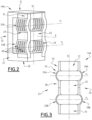
- dampers 14A to 14D are, for example, substantially identical. Thus, subsequently, only the damper 14A will be explained in detail with particular reference to the figure 2 and 3 respectively illustrating its perspective view and its front view in the state of rest.
- the damper 14 comprises an outer support structure 21, an inner support structure 22 and two pairs of membranes 23, 24 extending between the outer 21 and lower 22 structures.
- the external support structure 21 is intended to be in rigid contact with the satellite fixing structure and comprises for example suitable fixing means for this purpose.
- the outer support structure 21 forms a first attachment portion 31 and a second attachment portion 32 arranged opposite each other along a support axis X.
- the attachment portions 31, 32 are connected to each other by a connection portion 33 which, for example, forms a single piece with these attachment portions 31, 32.
- the external support structure 21 is present in the form of a "U" whose ends correspond to the fixing portions 31, 32.
- the attachment portions 31, 32 form separate parts intended for example to be attached to one or more satellite attachment structures separately.
- the inner support structure 22 is intended to be in rigid contact with the object 12 and according to an exemplary embodiment, comprises suitable fastening means for this purpose.
- the interior support structure 22 is integral with the object 12.
- the inner support structure 22 is connected to the outer support structure 21 via the pairs of membranes 23, 24.
- each pair of membranes 23, 24 is formed of a first membrane 33A, 34A extending between the inner support structure 22 and the first fixing portion 31 of the outer support structure 21, and of a second membrane 33B, 34B extending between the inner support structure 22 and the second fixing portion 32 of the outer support structure 21.
- the first membranes 33A, 34A of the pairs 23, 24 are arranged facing each other along a transverse axis Y 1 perpendicular to the support axis X and to an axis Z.
- the second membranes 33B , 34B of pairs 23, 24 are arranged opposite each other along a transverse axis Y 2 perpendicular to the support axis X and to the axis Z.
- the transverse axis Y 2 is therefore parallel to the transverse axis Y 1 .
- the membranes 33A, 34A, 33B, 34B are, for example, substantially identical.
- each membrane 33A, 34A, 33B, 34B is in the form of a flexible plate having two fixing ends and a flexible part extending between the fixing ends.
- the fixing ends 35, 36 and the flexible part 37 only of the membrane 33A, are referenced.
- each membrane 33A, 34A, 33B, 34B extends substantially along a single direction of extension presenting a rounded two-dimensional curve.
- the direction of extension D of the membrane 33A is visible on the figure 2 .
- each membrane 33A, 34A, 33B, 34B also extends substantially along a single direction of extension having a curvature different from that of the state of rest.
- each membrane 33A, 34A, 33B, 34B extends substantially along several intersecting directions of extension.
- each membrane 33A, 34A, 33B, 34B is flexed, which makes it possible to damp the vibrations of the first type along the support axis X, the transverse axes Y 1 and Y 2 , and the Z axis.
- Each membrane 33A, 34A, 33B, 34B is formed of a viscoelastic material comprising fibers aligned substantially in the same direction coinciding for example with the direction of extension of this membrane in the rest state. These fibers are for example Kevlar® fibers.
- At least some of the membranes 33A, 34A, 33B, 34B define at least one slot extending between the fixing ends of this membrane.
- the or each slot of the corresponding membranes extends substantially in the direction of extension of the corresponding membrane.
- the slots formed in the membranes make it possible to reduce the stiffness of the shock absorbers, in particular along the transverse axes Y 1 and Y 2 and along the Z axis by favoring the sliding between the different sections thus created, without impacting the stiffness along the support axis X. This then makes it possible to balance the stiffness along the three directions and to avoid an asymmetry in the system 10.
- each membrane 33A, 34A, 33B, 34B is, for example, made by simple compression type molding of a viscoelastic material with an aligned fiber structure. Then, the slits are formed on at least some of the membranes 33A, 34A, 33B, 34B with a suitable template.
- each of the dampers 14A to 14D is in the state of rest.
- micro-vibrations that is to say vibrations of the first type
- the fibers of each membrane work in flexion. This then makes the structure sufficiently flexible to filter these micro-vibrations along the support axis X, the transverse axes Y 1 and Y 2 , and the Z axis.
- the slots formed in the membranes make it possible to balance the distribution of stiffness along the different axes.
- the damping system according to the invention is particularly simple and compact. It dampens micro-vibrations while resisting high-level vibration environments, in all three dimensions. This therefore makes it particularly attractive for the space sector.
Landscapes
- Engineering & Computer Science (AREA)
- Remote Sensing (AREA)
- Aviation & Aerospace Engineering (AREA)
- Physics & Mathematics (AREA)
- General Engineering & Computer Science (AREA)
- Astronomy & Astrophysics (AREA)
- General Physics & Mathematics (AREA)
- Acoustics & Sound (AREA)
- Mechanical Engineering (AREA)
- Vibration Prevention Devices (AREA)
Applications Claiming Priority (2)
| Application Number | Priority Date | Filing Date | Title |
|---|---|---|---|
| FR1855815A FR3083279B1 (fr) | 2018-06-27 | 2018-06-27 | Amortisseur pour un objet place dans un milieu soumis a des vibrations et systeme d'amortissement correspondant |
| EP19182979.5A EP3587855B1 (de) | 2018-06-27 | 2019-06-27 | Dämpfer für ein objekt in einer vibrationsbeeinflussten umgebung und einem entsprechenden dämpfungssystem |
Related Parent Applications (1)
| Application Number | Title | Priority Date | Filing Date |
|---|---|---|---|
| EP19182979.5A Division EP3587855B1 (de) | 2018-06-27 | 2019-06-27 | Dämpfer für ein objekt in einer vibrationsbeeinflussten umgebung und einem entsprechenden dämpfungssystem |
Publications (2)
| Publication Number | Publication Date |
|---|---|
| EP4234972A2 true EP4234972A2 (de) | 2023-08-30 |
| EP4234972A3 EP4234972A3 (de) | 2023-09-27 |
Family
ID=63834162
Family Applications (2)
| Application Number | Title | Priority Date | Filing Date |
|---|---|---|---|
| EP23174930.0A Pending EP4234972A3 (de) | 2018-06-27 | 2019-06-27 | Dämpfer für ein objekt in einer vibrationsbeeinflussten umgebung und einem entsprechenden dämpfungssystem |
| EP19182979.5A Active EP3587855B1 (de) | 2018-06-27 | 2019-06-27 | Dämpfer für ein objekt in einer vibrationsbeeinflussten umgebung und einem entsprechenden dämpfungssystem |
Family Applications After (1)
| Application Number | Title | Priority Date | Filing Date |
|---|---|---|---|
| EP19182979.5A Active EP3587855B1 (de) | 2018-06-27 | 2019-06-27 | Dämpfer für ein objekt in einer vibrationsbeeinflussten umgebung und einem entsprechenden dämpfungssystem |
Country Status (4)
| Country | Link |
|---|---|
| US (1) | US11505335B2 (de) |
| EP (2) | EP4234972A3 (de) |
| ES (1) | ES2955170T3 (de) |
| FR (1) | FR3083279B1 (de) |
Families Citing this family (2)
| Publication number | Priority date | Publication date | Assignee | Title |
|---|---|---|---|---|
| US11506254B2 (en) * | 2020-05-26 | 2022-11-22 | Raytheon Company | Low profile shock isolating mount |
| US12472668B2 (en) * | 2022-07-29 | 2025-11-18 | Milacron Marketing Company Llc | Flex plate for guiding device of injection molding machine |
Family Cites Families (8)
| Publication number | Priority date | Publication date | Assignee | Title |
|---|---|---|---|---|
| GB1028884A (en) * | 1963-02-25 | 1966-05-11 | Lord Corp | Damped structure |
| US5178357A (en) * | 1989-08-16 | 1993-01-12 | Platus David L | Vibration isolation system |
| US5672228A (en) * | 1995-09-19 | 1997-09-30 | The United States Of America As Represented By The Secretary Of The Navy | Vibration-damping of structural products |
| GB0809231D0 (en) * | 2008-05-21 | 2008-06-25 | Esr Technology Ltd | Force applying mechanism |
| FR2967742B1 (fr) * | 2010-11-23 | 2013-11-22 | Astrium Sas | Dispositif d'isolation vibratoire |
| US8973937B2 (en) * | 2010-12-13 | 2015-03-10 | David Delon Williams | Shock absorber with compliant members |
| US9733027B2 (en) * | 2012-08-16 | 2017-08-15 | Minus K. Technology, Inc. | Thermal straps for spacecraft |
| EP3112721B1 (de) * | 2015-06-29 | 2018-04-25 | AIRBUS HELICOPTERS DEUTSCHLAND GmbH | Schwingungsisolierende vorrichtung für elastische kupplung zweier bauteile |
-
2018
- 2018-06-27 FR FR1855815A patent/FR3083279B1/fr active Active
-
2019
- 2019-06-27 EP EP23174930.0A patent/EP4234972A3/de active Pending
- 2019-06-27 ES ES19182979T patent/ES2955170T3/es active Active
- 2019-06-27 US US16/454,882 patent/US11505335B2/en active Active
- 2019-06-27 EP EP19182979.5A patent/EP3587855B1/de active Active
Also Published As
| Publication number | Publication date |
|---|---|
| EP3587855A1 (de) | 2020-01-01 |
| EP3587855B1 (de) | 2023-06-07 |
| FR3083279A1 (fr) | 2020-01-03 |
| EP4234972A3 (de) | 2023-09-27 |
| ES2955170T3 (es) | 2023-11-29 |
| FR3083279B1 (fr) | 2020-07-03 |
| EP3587855C0 (de) | 2023-06-07 |
| US20200002028A1 (en) | 2020-01-02 |
| US11505335B2 (en) | 2022-11-22 |
Similar Documents
| Publication | Publication Date | Title |
|---|---|---|
| WO2012069487A2 (fr) | Dispositif d'isolation vibratoire | |
| EP3587855B1 (de) | Dämpfer für ein objekt in einer vibrationsbeeinflussten umgebung und einem entsprechenden dämpfungssystem | |
| FR2670552A1 (fr) | Attache hydroelastique de suspension et biellette de liaison geometrique liee a cette attache. | |
| EP0207958B1 (de) | Hydraulisches antischwingungslager | |
| FR2560654A1 (fr) | Dispositif d'amortissement pour absorber ou compenser des chocs angulaires | |
| EP2966313A1 (de) | Dämpfer für eine Drehmomentübertragungseinrichtung eines Kraftfahrzeuges | |
| CA2633802C (fr) | Dispositif modulaire d'isolation multi-axes de vibrations et de chocs, a base d'elastomere | |
| EP2245332B1 (de) | Vorrichtung zum tragen und sichern eines bauteils eines flugzeugtriebwerks oder eines gondelgehäuses | |
| FR2832479A1 (fr) | Dispositif d'amortissement pour cable | |
| FR2948431A1 (fr) | Revetement isolant a masse amplifiee | |
| EP3071483B1 (de) | Satellitentragestruktur mit einer dämpfungsverbindungsvorrichtung | |
| EP4040005A1 (de) | Schwingungsfreie halterung und fahrzeug mit einer solchen schwingungsfreien halterung | |
| WO2020165128A1 (fr) | Dispositif comprenant un ensemble d'absorbeurs de vibrations et véhicule équipé d'un tel dispositif | |
| EP0122184B1 (de) | Antischwingungsaufhängung durch Gummifedern mit Nachstellung des Fliessens | |
| EP0045248B1 (de) | Stoss- und/oder schwingungsdämpfendes Lager | |
| FR2992039A1 (fr) | Dispositif de protection antichoc et antivibratoire d'un equipement embarque sensible aux accelerations | |
| EP2448818A1 (de) | System zur anbringung eines antriebsmotors | |
| FR2838173A1 (fr) | Element non-stucturel amortisseur pour structure susceptible d'etre soumise a des vibrations et structure equipee d'au moins un tel element amortisseur | |
| FR3081954A1 (fr) | Dispositif de piege vibratoire de torsion | |
| EP2444687B1 (de) | Isolierschutz mit ausgeweiteter Masse | |
| WO2025131788A1 (fr) | Dispositif de support d'un groupe motopropulseur de véhicule automobile | |
| EP4202252A1 (de) | Gedämpfte halterung zur anbringung einer ausrüstung an einem rahmen | |
| EP4166810A1 (de) | Schwingungsdämpfende medien zur dämpfung von nieder- oder hochfrequenz | |
| FR3021079A1 (fr) | Decoupleur pour dispositif de montage antivibratoire et dispositif de montage antivibratoire comprenant un tel decoupleur | |
| FR3102104A1 (fr) | Support moteur pour vehicule automobile |
Legal Events
| Date | Code | Title | Description |
|---|---|---|---|
| PUAI | Public reference made under article 153(3) epc to a published international application that has entered the european phase |
Free format text: ORIGINAL CODE: 0009012 |
|
| STAA | Information on the status of an ep patent application or granted ep patent |
Free format text: STATUS: THE APPLICATION HAS BEEN PUBLISHED |
|
| PUAL | Search report despatched |
Free format text: ORIGINAL CODE: 0009013 |
|
| AC | Divisional application: reference to earlier application |
Ref document number: 3587855 Country of ref document: EP Kind code of ref document: P |
|
| AK | Designated contracting states |
Kind code of ref document: A2 Designated state(s): AL AT BE BG CH CY CZ DE DK EE ES FI FR GB GR HR HU IE IS IT LI LT LU LV MC MK MT NL NO PL PT RO RS SE SI SK SM TR |
|
| AK | Designated contracting states |
Kind code of ref document: A3 Designated state(s): AL AT BE BG CH CY CZ DE DK EE ES FI FR GB GR HR HU IE IS IT LI LT LU LV MC MK MT NL NO PL PT RO RS SE SI SK SM TR |
|
| RIC1 | Information provided on ipc code assigned before grant |
Ipc: F16F 15/073 20060101AFI20230822BHEP |
|
| STAA | Information on the status of an ep patent application or granted ep patent |
Free format text: STATUS: REQUEST FOR EXAMINATION WAS MADE |
|
| 17P | Request for examination filed |
Effective date: 20240314 |
|
| RBV | Designated contracting states (corrected) |
Designated state(s): AL AT BE BG CH CY CZ DE DK EE ES FI FR GB GR HR HU IE IS IT LI LT LU LV MC MK MT NL NO PL PT RO RS SE SI SK SM TR |
|
| STAA | Information on the status of an ep patent application or granted ep patent |
Free format text: STATUS: EXAMINATION IS IN PROGRESS |